1
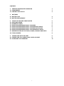
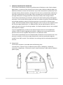
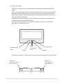
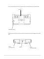
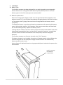
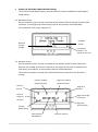
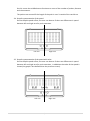
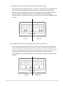
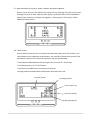
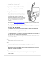
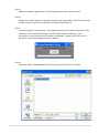
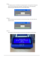
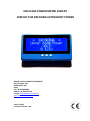
ERCOLINA POWER METER DISPLAY
DISPLAY FOR ERCOLINA UPPER BODY POWER
MIRCO COLLAVO SPORTS EQUIPMENT
Via del Fagher 12b
32030 Quero (BL)
ITALY
Tel +39 0439788509
Mobile +39 3284174159
e-mail: [email protected]
www.upperbodypower.com
January 2013
Firmware Release v 0.4
This page is intentionally left blank
CONTENTS
1. ERCOLINA POWER METER OVERVIEW
1.1 COMPONENTS
1.2 CENTRAL UNIT LAYOUT
1
1
3
2. BATTERIES
2.1 BATTERY TYPE
2.2 BATTERY REPLACEMENT
4
4
3.
3.1
3.2
3.3
3.4
3.5
3.6
3.7
3.8
5
5
5
6
6
7
7
8
8
USING THE ERCOLINA POWER METER
WELCOME SCREEN
WORKOUT SCREEN
GRAPHIC RAPPRESENTATION OF THE SPEED
GRAPHIC RAPPRESENTATION OF THE SPEED WITH VALUE
GRAPHIC RAPPRESENTATION OF THE FORCE WITH VALUE
GRAPHIC RAPPRESENTATION OF THE POWER WITH VALUE
REPRESENTATION OF THE FORCE, POWER, CADENCE AND SPEED
TOTALS SCREEN
4. CONNECTION WITH USB PORT
4.1 CONNECTION TO A POWER SUPPLY WITH USB PORT
4.2 UPGRADING THE FIRMWARE
i
9
9
11
1. ERCOLINA POWER METER OVERVIEW
The Ercolina Power Meter analyze the performances of athletes on the Ercolina Upper
Body Power: it measure of the speed of the Ercolina sides FOR EACH SINGLE ARM, and
dedicated software execute the calculations to provide instantaneous speed (km/h, left
and right value), distance (meters, average of the two arms), instantaneous cadence for
each push (push/minute, left and right value), average force for each push (in kgs, left
and right value) and average power for each push (in watts, left and right value).
The Ercolina Power Meter give all these measures for both double poling and diagonal
technique. The internal memory keeps the total for number of pushes, covered distance
and average speed also when the Ercolina computer is turned off or without power
supply. The Ercolina Power Meter weight 500 grams, and it is easy to carry together with
the Ercolina Upper Body Power: it is powered from normal 4xAA batteries, that can
endure for up to 10 hours of training outdoor : for fixed installation there is the included
220v AC/DC 5V adapter.
It can be upgraded easily, thanks to the USB connection with a PC and a dedicated
software. We will release upgrades periodically , adding new screens and functions.
Special screens can be supplied "ad personam" for particular needs.
The Ercolina Power Meter can be ordered already installed on a new Ercolina, but it can
be easily installed on all Ercolina Upper Body Power machines produced (magnetic
models) since 2007 onward. The installation on existing machines take approximately 15
minutes.
1.1 Components
The Ercolina computer is provided with the following parts:
1 Central Unit, 2 Sensors strips, 3 Adhesive square tapes, 2 Magnets, 2 Cables for
connection, 1 Applicator, 2 Screws for sensors strips mounting, 1 Wall cube for USB port
power supply
1 | 11
1.2 Central Unit Layout
The Ercolina computer is controlled with the 3 frontal buttons and a backside reset
button.
There is not on/off button because the Ercolina computer can sense the functioning of
the Ercolina Upper Body Power and automatically turn on if movement is detected.
The Ercolina computer turns automatically in low consumption mode if the Ercolina is
not used for about 26 seconds.
If the Ercolina Upper Body Power is not used for about 1 minute and 15 seconds, the
Ercolina computer turns automatically off.
The function of the buttons at the time of the release v0.4 of the inner software is
described in the following picture:
Unimplemented
button
Left led
Reset
chronometer
button
Mode button
Right led
The Ercolina computer is connected to two sensor strips via two slots on the upper side:
Slot for the
Connector to the
left sensor strip
Slot for the
Connector to the
right sensor strip
2 | 11
On the back side of the Ercolina computer there is another button for the global reset.
Speaker
Global Reset button
On the bottom side there are the two battery compartments Left and Right, and the USB
port.
Battery
compartment Left
USB port
3 | 11
Battery
compartment Right
2. BATTERIES
2.1 Battery Type
The Ercolina computer has been designed for use with disposable not rechargeable
alkaline batteries or rechargeable Nickel Metal Hydride (NiMH) batteries. No other
battery types or mix of the two types are recommended.
2.2 Batteries replacement
When the average cells voltage is under 1.0 V the signal of low battery appear on the
welcome screen (“lo”), the Ercolina Power Meter change brightness and other functions
to “low power mode” giving a few extra hours of usage before the battery run out
completely.
To change the battery , open the two batteries compartments by removing the battery
covers, left and right, and fit 4 “AA” batteries. Take care to ensure they are fitted with
the correct battery polarity. Replace the battery covers.
Training data are saved in the inner memory when the Ercolina Power Meter shut down
(sleep mode) automatically after 1 minute and 15 seconds of inactivity, to avoid data
loss wait that the Ercolina Power Meter enter sleep mode, and then change the
batteries.
The Ercolina computer can function also with only 2 “AA” batteries.
The battery charger is not included. Connecting a 5V power supply via the USB port the
Ercolina computer use the USB power supply and the batteries are automatically
disconnected from the circuit.
Always dispose of depleted batteries using approved disposal methods that protect the
environment.
Push for opening
the batteries
compartment
4 | 11
3
USING THE ERCOLINA POWER METER DISPLAY
The Ercolina Power Meter Display, provide different screens modalities by pushing the
mode button:
3.2 Welcome screen
On the welcome screen the user can observe the release of the Firmware of the Ercolina
computer, the voltage level of the battery cells or the presence of an USB cable
connected with a 5V power supply or PC.
Firmware
release
Batteries
average
voltage
Low battery
indicator “Lo”
appear in this area
3.3 Workout screen
On the workout screen, the user can observe the speed in km/h for each side of the
Ercolina, the number of pushes for each arm, the length of the push (in rounds of the
cord drum), the cadence, a chronometer and the covered distance.
The Ercolina computer increase the time and the distance only when the Ercolina is
moving.
Left arm cadence
[pushes/minute]
Right arm cadence
[pushes/minute]
Left arm
pushes
Right arm
pushes
Left arm
length of
the push
Right arm length
of the push
Right arm
Speed [km/h]
Left arm
Speed [km/h]
Chronometer
HH:MM:SS.D
Distance [meters]
5 | 11
On this screen the middle button function as a reset of the number of pushes, distance
and chronometer.
The pushes are counted if the length of the push is over 2 rounds of the cord drum.
3.4 Graphic representation of the speed
On the Graphic speed screen, the user can observe if there are differences in speed
between left and right arm for push execution.
Left arm
Right arm
3.5 Graphic representation of the speed with value
On the Graphic speed screen, the user can observe if there are differences in speed
between left and right arm for push execution , in addiction the value of the speed is
shown (the graph is less defined than the previous screen).
Left arm
Right arm
6 | 11
3.5 Average force calculation with graphic representation of the speed
On the average force calculation screen, the user can observe if there are differences in
force between left and right arm for push execution, in addiction the speed of the
execution is graphically represented. The Force calculation is correct while the force is
enough to keep the flywheel rotating for 2 rounds after the end of the poling.
The average force is calculated for each push and the value is showed immediately after
the push.
Left arm
Right arm
3.6 Average power calculation with graphic representation of the speed
On the average power calculation screen, the user can observe if there are differences
in power between left and right arm for push execution, in addiction the speed of the
execution is graphically represented. The Power calculation is correct while the force is
enough to keep the flywheel rotating for 2 rounds after the end of the poling.
The average power is calculated for each push, the value is showed immediately after
the push
Left arm
Right arm
7 | 11
3.7 Representation of the force, power, cadence and speed together
On this screen the user can observe the values of Force (average for push) in kg, Power
(average for push) in watt, cadence (each push) in pushes/minute and instantaneous
speed of the machine in km/hour, all together: refer to point 3.5 and point 3.6 for
additional information’s.
3.8 Totals screen
On the totals screen the user can observe the total work done with the Ercolina , the
reset button or the exhaustion of the battery has no effect, the data are stored in the
permanent memory of the Ercolina computer, and are the following:
-Total pushes divided between left and right arm, up to 16.777.215 pushes
-Total distance up to 16.777.215 meters
-Total time up to 4660 hours 20 minutes 15 seconds
-Average speed calculated with total distance and total time ratio.
Total Left pushes
Total Right pushes
Total distance [m]
Total time [H:M:S]
Average Speed [km/h]
8 | 11
4
CONNECTION WITH USB PORT
4.1 Connection to a power supply with usb port
The Ercolina Power Meter Display is supplied
with a wall cube 5V DC with mini USB connector
See the picture aside.
4.2 Upgrading the Firmware
The Ercolina Power Meter Display is still in its
infancy. The software of the microcontroller is
in evolution, the number of screens here
described is based on the V0.4 of the firmware,
more screens and functions will be added and
the user can keep the Ercolina computer
updated.
On the web site www.upperbodypower.com is available under the Downloads menu,
the Folder dedicated to the Ercolina Power Meter.
There are two files; one file is the Software to install on the computer to connect with
the Ercolina.
It is called: “epm_code_vx.x.hex”
The other file is the version of the Firmware available to update the Ercolina Power
Meter.
The file it is called: “Powerup for Windos XP.zip”
The upgrade software at the moment is only available for Windows Vista, XP, 2000, NT,
98; other Operative Systems will be supported soon.
The following steps are necessary to upgrade the Ercolina Power Meter to the newest
version of the software.
STEP 1
Download the two files from the web site
STEP 2
Click on the zip file and then Install the program Powerup.exe on your PC
STEP 3
Dismount the Ercolina Power Meter from the Ercolina and then connect it to your PC
with a mini USB cable (not included)
STEP 4
On the Ercolina Power Meter, press simultaneously, the two buttons “global
reset”+”mode”
9 | 11
STEP 5
Release the button “global reset” while keeping pressed the “mode” button
STEP 6
Release the “mode” button, at this point the Ercolina Power Meter enter the connection
modality and it is ready for the Update, the right led should be on
STEP 7
Start the program “powerup.exe”, this program sense the connection with the Ercolina
computer and it shows the message “Ercolina Power Meter connected”, if the
connection is not successful, and it remains “disconnect” repeat from STEP 4 until it
shows the connected message. Click on “Update”.
STEP 8
Select the “hex” file downloaded from the web site and then click on “Open”
10 | 11
STEP 9
The update process is indicated by the progressing bar, the progress bar will go two
times one for writing process and one for verifying process; in this state avoid
disconnecting the USB cable from the Ercolina Power Meter.
STEP 10
When the process end successfully the Ercolina Power Meter will restart from the
welcome screen.
STEP 11
Disconnect the USB cable and mount the Ercolina Power Meter on the Ercolina.
11 | 11