1
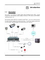
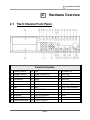
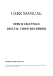
Digital Video Recorder
KA-9009 KA-9016
User Manual
Version: 1.8
Date: January 07, 2007
WARRINGS, CAUTION & COPYRIGHT
WARINGS
Reduce the risk of fire or electric shock. And do not expose this product to rain.
Do not insert any metallic object through ventilation grills.
CAUTION
The lightning flash with arrowhead symbol,
within an equilateral triangle, is intended to
alert the user to presence of insinuated
“dangerous voltage” within the products
enclosure that may be of sufficient magnitude
to constitute a risk of electric shock to persons
The exclamation point within an equilateral
rhombus is intended to alert the user to the
presence of important operating and
maintenance (servicing) instruction in the
literature accompanying product.
RISK OF ELECTRIC SHOCK DO NOT OPEN
TO REDUCE TE RISK OF ELECTRIC SHOCK
DO NOT REMOVE COVER (OR BACK).
NO USER-SERVICEABLE PARTS INSIDE
REFER SERVICING TO QUALIFIED SERVICE
USER OF THE SYSTEM ARE RESPONSIBLE FOR CHECKING AND COMPLYING WITH
ALL FEDERAL, STATE, AND LOCAL LAWS AND STATUTES COIPCERNING THE
MONITORING AND RECORDING OF VIDEO AND AUDIO SIGNAL. ULTRAK SHALL NOT
BE HELD RESPONSIBLE FOR THE USE OF THIS SYSTEM IN VIOLATION OF CURREENT
LAWS AND STATUTES.
CONTENTS
CONTENTS:
□
1.
INTRODUCTION ............................................................................................ 4
1.1 ILLUSTRATION ............................................................................................................................ 4
□
2.
HARDWARE OVERVIEW ............................................................................. 5
2.1 THE 9 CHANNEL FRONT PANEL .................................................................................................... 5
2.2 THE 9 CHANNEL BACK PANEL ...................................................................................................... 6
2.3 THE 16 CHANNEL FRONT PANEL .................................................................................................. 7
2.4 THE 16 CHANNEL BACK PANEL .................................................................................................... 8
2.3 BASIC CONTROL INTERFACE ........................................................................................................ 9
2.4 BUTTON CONTROL INTERFACE ................................................................................................... 10
2.5 PLAYBACK CONTROL INTERFACE ............................................................................................... 12
2.6 IMAGE DISPLAY MODE............................................................................................................... 14
2.7 IMAGE INPUT AND OUTPUT ........................................................................................................ 16
2.8 AUDIO INPUT AND OUTPUT ........................................................................................................ 16
2.9 ALARM CONTROL ...................................................................................................................... 17
2.10 NETWORK FUNCTION ............................................................................................................... 19
□
3.
FUNCTION SETTING .................................................................................. 20
3.1 SYSTEM SETUP ..................................................................................................................... 21
3.1.1 TIME/DATE SETUP ........................................................................................................ 21
3.1.2 HDD FORMAT SET ......................................................................................................... 21
3.1.3 FACTORY RESET............................................................................................................ 22
3.1.4 PLAY REPEAT ................................................................................................................. 22
3.1.5 VIDEO SYSTEM ............................................................................................................. 22
3.1.6 BUZZER SOUND ............................................................................................................ 22
3.1.7 CHANGE PASSWORD .................................................................................................... 23
3.1.8 FIRMWARE UPDATE ..................................................................................................... 23
3.1.9 LANGUAGE SELECT SET ............................................................................................. 23
3.2 DISPLAY SET .......................................................................................................................... 24
3.2.1 CAMERA NAME ............................................................................................................. 24
3.2.2 COLOR SET..................................................................................................................... 24
3.2.3 AUTOSEQ SET ................................................................................................................ 24
Page 1
CONTENTS
3.2.4
3.2.5
BOUND COLOR .............................................................................................................. 25
BLANK COLOR .............................................................................................................. 25
3.3 RECORD SET .......................................................................................................................... 26
3.3.1 OVER WRITE .................................................................................................................. 26
3.3.2
REC SPEED ..................................................................................................................... 26
3.3.3
3.3.4
REC QUALITY ................................................................................................................ 26
RESOLUTION ................................................................................................................. 27
3.3.5
3.3.6
PB SPEED ........................................................................................................................ 27
RECORD CH SET ............................................................................................................ 27
3.3.7 AUDIO SELECT .............................................................................................................. 27
3.4 NETWORK SET ...................................................................................................................... 28
3.4.1 IP ADDR (Address) .......................................................................................................... 28
3.4.2 GATEWAY ....................................................................................................................... 28
3.4.3 SUB NET.......................................................................................................................... 28
3.4.4 IP MODE .......................................................................................................................... 28
3.4.5 DDNS ENV ...................................................................................................................... 29
3.4.6 NETWORK ENV ............................................................................................................. 30
3.4.7 N/W ENABLE .................................................................................................................. 30
3.4.8 VIDEO PORT ................................................................................................................... 30
3.4.9 COMMAND PORT .......................................................................................................... 30
3.5 SENSOR SET ........................................................................................................................... 31
3.5.1 CHANNEL SELECT ........................................................................................................ 31
3.5.2 ALARM ENABLE ........................................................................................................... 31
3.5.3 MOTION ENABLE .......................................................................................................... 31
3.5.4 MOTION LEVEL ............................................................................................................. 31
3.5.5 MOTION AREA SET ....................................................................................................... 32
3.5.6 BUZZER TIME ................................................................................................................ 32
3.5.7 SENSE RECTIME ............................................................................................................ 32
3.6 SCHEDULE SET ..................................................................................................................... 33
3.7 BACKUP SET .......................................................................................................................... 34
3.7.1 USB BACKUP ................................................................................................................. 34
3.7.2 CDRW BACKUP .............................................................................................................. 35
3.7.3 ERASE CD ....................................................................................................................... 36
3.8 STORAGE INFO ...................................................................................................................... 36
□
4.
PLAYBACK ................................................................................................... 37
4.1 DVR PLAYBACK........................................................................................................................ 37
4.2 USB PLAYBACK ........................................................................................................................ 39
Page 2
CONTENTS
4.3 CD PLAYBACK .......................................................................................................................... 40
□
5.
NETWORK FUNCTION .............................................................................. 41
5.1 ILLUSTRATION .......................................................................................................................... 41
5.2 REMOTE VIEW ........................................................................................................................... 41
5.3 FUNCTION ................................................................................................................................. 43
5.3.1 VIEW ............................................................................................................................... 43
5.3.2
SYSTEM .......................................................................................................................... 44
5.3.3
5.3.4
NETWORK ...................................................................................................................... 45
ADVANCED .................................................................................................................... 46
5.3.5
STATUS ............................................................................................................................ 46
APPENDIX A: IR REMOTE CONTROLLER ........................................................................................... 47
APPENDIX B: THE DVR FIRMWARE UPGRADE................................................................................... 48
APPENDIX C: DDNS APPLICATION................................................................................................... 49
APPENDIX D: VGA FUNCTION ......................................................................................................... 52
APPENDIX E: HOW TO SET UP THE DVR THROUGH ROUTER .............................................................. 53
Page 3
1.
□
1.
□
Introduction
Introduction
1.1 Illustration
The system is the MJPEG 16 Channel Digital Video Recording System (DVR). System
designed with simply operation mode to adding new button on OSD interface, WATERMARK,
Jog Shutter Switch…etc.
Basic operation mode: MONITOR, PLAYBACK and SETTING. User can use OSD interface or
IR remote controller to operate the function and setting. The DVR can support multiple works
like view images, recording, playback and remote control at the same time.
Page 4
2.
□
2.
□
Hardware Overview
Hardware Overview
2.1 The 9 Channel Front Panel
Function Interface
1
Camera Channel
13
LIVE
25
POWER LED
2
Direction Control
14
Screen Display: 9CH
26
HDD LED
3
ENTER
15
QUAD Screen Display
27
Rewind LED
4
Fast Rewind
16
MENU
28
Play LED
5
Rewind
17
ZOOM
29
Record LED
6
Pause
18
AUTO
30
USB Flash LED
7
Stop
19
INFO
31
USB Flash Connecter
8
Play
20
WATERMARK
32
IR Receiver
9
Fast Forward
21
USB Backup
33
DVD (Only Support CDRW)
10 Recording
22
RECORD SEARCH
34
HDD
11 Jog Shutter Switch
23
TIME SEARCH
12 Filed to Filed Select
24
EVENT SEARCH
Page 5
2.
□
Hardware Overview
2.2 The 9 Channel Back Panel
Hardware Interface
6
Monitor OUT
11
75 ohm &
Signal Adjustment
7
RJ45 Connecter
12
Video Input (1~9 CH)
3 FAN
8
RS-485 D-Sub Connecter
13
Network Connection LED
4 Audio IN
9
RS-232 D-Sub Connecter
14
Network Data LED
5 Audio OUT
10
Video Output (1~9 CH)
1 Power ON/OFF
2
AC 90~260 V
Switching Power
Page 6
2.
□
Hardware Overview
2.3 The 16 Channel Front Panel
Function Interface
1
Camera Channel
13
Screen Display: 13CH / 16CH
25
POWER LED
2
Direction Control
14
Screen Display: 8CH / 9CH
26
HDD LED
3
ENTER
15
QUAD Screen Display
27
Rewind LED
4
Fast Rewind
16
MENU
28
Play LED
5
Rewind
17
ZOOM
29
Record LED
6
Pause
18
AUTO
30
USB Flash LED
7
Stop
19
INFO
31
USB Flash Connecter
8
Play
20
WATERMARK
32
IR Receiver
9
Fast Forward
21
USB Backup
33
DVD (Only Support CDRW)
10 Recording
22
RECORD SEARCH
34
HDD
11 Jog Shutter Switch
23
TIME SEARCH
12 Filed to Filed Select
24
EVENT SEARCH
Page 7
2.
□
Hardware Overview
2.4 The 16 Channel Back Panel
Hardware Interface
6
Monitor OUT
11
75 ohm &
Signal Adjustment
7
RJ45 Connecter
12
Video Input (1~16 CH)
3 FAN
8
RS-485 D-Sub Connecter
13
Network Connection LED
4 Audio IN
9
RS-232 D-Sub Connecter
14
Network Data LED
5 Audio OUT
10
Video Output (1~16 CH)
1 Power ON/OFF
2
AC 90~260 V
Switching Power
Page 8
2.
□
Hardware Overview
2.3 Basic Control Interface
The Chapter will explain how to use OSD basic function through the “SETTING” mode. Please
follow the illustration item as below:
MENU Button:
In the “MONITOR” mode, press the “MENU“ button to
change the viewing mode to the “SETTING” mode. The
“SETTING” mode offers 8 kinds of sub-mode. Please
select the sub-mode through the “Control” button. The
sub-mode signal will change from square to circle, and font
color also will change to yellow. The default selection is
“SYSTEM SET”.
In the “SETTING” mode, the “MENU” button function will change to EXIT function. If you press
the “MENU” button in the “SETTING” mode, you will go back to the “MONITOR” mode. The
DVR will record all modification automatically.
Control & ENTER Button:
In the “SETTING” mode, you can select the setting item through “
or OFF the setting function through “
”,”
” or “
” Button, then ON
”,” ” button.
Button:
:
Enter the sub-mode or other setting item. However the “ENTER” button will provide different
function under other function mode.
or
Button:
:
You can enable, disable or change function, but different sub-mode will display distinct
description. For example: YES / NO、ON / OFF…
NOTE:
:
The detailed explanation of “ENTER” button will be illustrated in every chapter.
Page 9
2.
□
Hardware Overview
2.4 Button Control Interface
The Chapter will explain How to use panel button function. Some button function will use in
the “MONITOR” mode or the “SETTING” mode. Please follow the item illustration as below:
ZOOM:
Use the zoom-in function in the “MONITOR”
mode or the “SETTING” mode. The zoom-in
function is double digital amplification.
Press the “ZOOM” button and it will pop the 1/4
square on the monitor. If you press again, the
system will go back to the “MONITOR” mode.
You can set up the 1/4 square area through “
“
”
”
”
”
”
” button, and then press the
“ENTER” button to amplify the image. If you
press again, the size of image will become the
normal one.
NOTE:
:
You can still zoom-in through the “Control” button.
LIVE (For 9CH model only):
In the “PLAYBACK” mode, Go back to “MONITOR” mode easy and quick. The “LIVE” button
likes the EXIT function, but it only work in the “PLAYBACK” mode.
AUTO:
In the “MONITOR” mode, the monitor will go
into the full screen auto switch mode, the
default time is 2 seconds. Found on the
chapter of 3.2.3 “AUTOSEQ SET”.
Page 10
CH01 CH02 CH03 CH04 ….. CH16
2 Sec
2 Sec
2 Sec
2 Sec
2.
□
Hardware Overview
INFO:
In the “MONITOR” mode, easy to view all information of the DVR HDD, Recording, Network and
firmware. Press the button again to leave the “INFO” state.
HDD MODEL
:HDD board
HDD SIZE
:HDD space
HDD USER
:HDD used ratio
HDD READ
:Function preserver
OVERWRITE
:Count the overwrite times
REC LIST
:Recording list
EVENT LIST
:Alarm recording list
REC OVER
:Function preserver
EVENT OVER :Function preserver
NETWORK IP :Now IP address
S/W VER
:Now firmware version
WATERMARK:
In the “PLAYBACK” mode, the WATERMARK function would protect
recording image images. No one can easily modify the files. The
mark function would keep on display on image wherever in every
viewing mode of “PLAYBACK”.
USB:
The function can back up direct monitor image despite in the “MONITOR” or “PLAYBACK”
mode. Please make reference to the chapter of 3.7.1 USB BACKUP for further detailed
description.
RECORD / TIME / EVENT SEARCH:
To search the playback image through different method of RECORD / TIME / EVENT SEARCH
Button.
Page 11
2.
□
Hardware Overview
2.5 Playback Control Interface
The Chapter will explain How to use panel button for playback function. It mainly use in the
“MONITOR” mode. Please follow the item illustration as below:
Recording:
The DVR support multiple working. You can view, record, playback and remote control at the
same time. If the recording function works, the Record LED will become red. Press the
button again then the recording function will be cancelled.
Play:
Change DVR mode from “MONITOR” to “PLAYBACK”. The screen image
will be change to recording files. And this is the same as the first data on
“RECORD SEARCH” state.
Press the “ ” Stop Button to go back to the “MONITOR” mode.
Rewind:
In the “PLAYBACK” mode, press the “ ” Rewind Button and it will rewind
the recording image. The “ ” Rewind Button sign will display on the
upper-left side of the monitor. If you need to go back to the “Play State”,
please press the “ ” Pause Button.
Pause:
In the “PLAYBACK” of “Play State” or “Rewind State”, it can pause on the
recording image directly. If you need to go back to “Play State”, please
press the “ ” Pause Button directly.
If you press the button to the “Fast Rewind State” or “Fast Forward State”,
the DVR mode will go back to the “Play State” to play the recording image.
Page 12
2.
□
Hardware Overview
Stop:
In the “PLAYBACK” mode, you can press the “
“MONITOR” mode.
” Stop Button anytime to go back to the
Fast Rewind:
In the “PLAYBACK” mode, Press the “ ” Fast Rewind Button to change
the image rewind speed: X2, X4, X8 and X16. The “ ” Fast Rewind
Button sign and the speed state will display on the upper-left side of the
monitor.
Fast Forward:
In the “PLAYBACK” mode, Press the “ ” Fast Forward Button to change
the image forward speed: X2, X4, X8 and X16. The “ ” Fast Forward
Button sign and the speed state will display on the upper-left side of the
monitor.
NOTE:
:
If you press the “Fast Rewind Button” under the fast play speed state, it will reduce the level
of the speed. If you press the “Fast Forward Button” under the fast forward speed state, it
will reduce the level of speed as well.
Jog Shutter switch:
You can change the image speed in the “PLAYBACK” mode. Jog
Shutter switch turn to left or right to change the playback image speed.
Turn right is the fast forward function: X8 and X16. Turn left is the fast
rewind function: X4, X8 and X16. The sign and speed state will display
on the upper-left side of the monitor.
Filed to Filed Select:
The function used in the “PLAYBACK” of “Pause State”. Revolve the “Filed
to Filed Select” of “Jog Shutter Switch” to display the recoding picture.
Revolve right to display the next picture, and revolve left to display the
Rewind one.
Page 13
2.
□
Hardware Overview
2.6 Image Display Mode
User can change the different viewing mode in the “MONITOR” mode. The DVR provides 6
kinds of viewing mode: full format, QUAD, 8 channels, 9 channels, 13 channels and 16
channels.
1
~
16
Full Format:
You can view the channel of full format through 1~9/1~16 button.
NOTE:
:
There are the “SEQ” and “3x3” button on the 9 CH “Camera Change” panel. The “SEQ”
button is the same “AUTO” function, other “3x3” button is the same “ ” function.
QUAD:
You can view the 4 channel QUAD through “ ” button. Press the “ ” button again to replace
other 4 cameras.
The 9 CH DVR of QUAD image can be two types of 01~04 and 05~08 channels. The 16 CH
DVR of QUAD image can be four types of 01~04, 05~08, 09~12 and 13~16 channels.
9CH DVR
16CH DVR
Page 14
2.
□
Hardware Overview
8CH / 9CH Display:
You can view the 9 channel through “ ” button. Press the “ ” button again and it will replace
other 9 channel camera. The 9 channel can change 2 types of 01~09 and 08~16 channels.
Press the button again will change to PIP state of 8 channels. It can change 2 types of 01~08
and 09~16 channels. The 16 CH DVR of “ ” totally provide 4 types viewing modes.
However, The 9 CH DVR only provide one type viewing mode.
13CH / 16CH Display (For 16 CH model only):
You can view the channel of 16 channel through “ ” button. Press the “ ” button again and it
will change viewing mode to 13 PIP state to displays the 01~13 channels.
Page 15
2.
□
Hardware Overview
2.7 Image Input and Output
The DVR provides 9CH/16CH video input and output channels. If you connect many monitors
or DVRs through video out, it will affect the image quality and stability.
You can adjust the
video signal control extend.
75 Ω:
:
Normal State.
Auto gain state, to extend the camera output signal.
If you connect many DVRs, you need to
change the video IN&OUT switch to 75
ohm on the last DVR. Let the DVR
know the end of connection.
….. 75 ohm
2.8 Audio Input and Output
Connect audio IN or OUT devices through RCA interface.
Audio IN:
Extra connect other devices or microphone.
Audio OUT: Extra connect other devices or loudspeaker.
NOTE:
:
The Audio function can not guarantee power issue. Please notice whether the microphone
spec can use or not.
Page 16
2.
□
Hardware Overview
2.9 Alarm Control
There are three types of alarm trigger signal can be identified: Motion Detection alarm, Extra
Alarm and Video Loss Alarm.
NOTE:
:
The built-in buzzer default time is 5 seconds.
Motion Detection Alarm:
:
You can set up the motion detection alarm function in the “SETTING”
mode. When motion detection triggered, system would record image
and enable the buzzer. Meanwhile, the trigger camera channel will
display the “Recording” sign and “M” sign.
Please make reference to the chapter of 3.5 SENSOR SETUP for
further detailed description.
Video Loss Alarm:
:
When camera’s power or BNC connecter had some problem to cause
video loss, the blue image & “L” sign will be display on the problem
channel.
NOTE:
:
When video loss alarm detection, the recording function would failed. Please enable the
recording function again after fix the video loss.
Extra Alarm:
:
The DVR offer the 16 alarm input and the one alarm output. When
extra alarm triggered system would record image and enable the
buzzer. Meanwhile, the trigger camera will display the “Recording”
sign and “A” sign.
Page 17
2.
□
Hardware Overview
25 PIN D-SUB Connecter:
:
The 25 PIN D-SUB Connecter supply the extra trigger-in & out alarm device and RS485 contact.
The DVR only receive TTL/COMS alarm signal that the LOW & HIGH of potential or the N.O &
N.C state.
25 PIN D-SUB Connecter
PIN
Definition
01~12
01~12 Alarm Input
14~17
13~16 Alarm Input
18
RS485A
19
RS485B
21
Relay COM
22
Alarm Output N.C
23
Alarm Output N.O
13,20,24,25
GND
Page 18
2.
□
Hardware Overview
ALARM INPUT:
:
You can extra connect the 16’s alarm input. The extra device connects one for the alarm input,
the other for GND. The security setting could support N.C or N.O function. Please make
reference to the chapter of 3.5.2 ALARM ENABLE.
ALARM OUTPUT:
:
You can extra connect the one alarm output. The extra device connects one for PIN 22(N.C)
or PIN 23(N.O) of the alarm output, the other for GND. Because of the DVR can not supply any
power for extra device, you can connect the power adapter through PIN 21(COM) to provide
electric power. When alarm trigger, the alarm output will work.
PTZ (Speed Dome):
:
Function under modification (See further Appendix announcement).
2.10 Network Function
You can view the DVR image through “IE browser” support remote control and remote
recording function. There are three types of network mode: STATIC IP, DHCP and PPPoE.
Ethernet LED of Connection:
:The LED is bright after RJ45 connecter link succeed.
Ethernet LED of Data:
:When data transmit, the LED will bright.
Ethernet LED of Connection
Ethernet LED of Data
Page 19
3.
□
3.
□
Function Setting
Function Setting
In the “MONITOR” mode, press the “MENU” button to enter the “SETTING” mode.
3.1
3.4
3.6
3.7
3.2
3.3
3.8
3.5
Page 20
3.
□
Function Setting
3.1 SYSTEM SETUP
In he “SYSTEM SET” mode, press the “ENTER” button to go
into SYSTEM SETUP.
Select the setting item through “
” or “
” button. Please
follow the function illustration as below:
3.1.1
TIME/DATE SETUP
Set up the time / date on DVR. There are five types of function setting such as: DATE, TIME,
FORMAT, DISPLAY and LOCAL.
In the “TIME/DATE SETUP”, press the “
” or “
” button to select item of DATE, and then
press the “ ” or” ” button to modify the figure of DATE.
DATE:
:There are 3 kinds of selection setting including year,
month and date.
TIME:
: There are 3 kinds of selection setting including Hour,
minute and second.
FORMAT:
:There are 3 kinds of selection setting including
YYY/MM/DD, MM/DD/YYYY and DD/MM/YYYY.
YYYY
means year, MM means mouth, and DD means date
DISPLAY:
: You can set up to enable/disable display the
TIME/DATE information. The selection item is ON/OFF.
3.1.2
HDD FORMAT SET
It can provide to format the HDD data function. The format
HDD means to delete the recording data. If you use this
function, the systems will double check with users.
Page 21
3.
□
3.1.3
Function Setting
FACTORY RESET
The DVR can repeat to get the factory default figures through
this function. If you will use this function, the systems will
double check with users.
“YES” of selection will reset the
DVR to factory default figure.
3.1.4
PLAY REPEAT
This function only works in the “PLAYBACK” mode.
If the recording image played in the end,
the system will automatically repeat to play recording image. Press the “ ” or “ ” button to
open/close this function ON/OFF.
3.1.5
VIDEO SYSTEM
The DVR supply NTSC/PAL video system switched for the country of world.
agree with local frequency.
3.1.6
You can select to
Press the “ ” or “ ” button to switch the NTSC or PAL.
BUZZER SOUND
Operate the OSD interfaces which supply the keypad tone function. Press the “ ” or “ ” button
to open/close the buzzer sound ON/OFF.
Page 22
3.
□
3.1.7
Function Setting
CHANGE PASSWORD
There are 4 kinds of password mode for user including NO
USE / SYSTEM / ALWAYS / SETUP.
passwords except NO USE.
They all need the
If enable the password
function, the system will request 4 bytes numbers for the
password. Press the “
” or “
” button to select
password’s number.
NOTE:
:
The default password is “0000”. The “10” number keyed has indicated the “0” number.
Three types of SYSTEM / ALWAYS / SETUP mode can set up the passwords at the same
time. The default password setting is the SETUP mode.
3.1.8
FIRMWARE UPDATE
The DVR provide simple update method for user. You can
update the DVR firmware version through USB flash.
Please make reference to the chapter of Appendix B
Upgrade the DVR firmware for the further detailed
description.
3.1.9
LANGUAGE SELECT SET
There are two basic “Chinese” and “English” types of language selections for user.
“ ” or “ ” button to switch the language selection.
NOTE:
:
Further language version could be update under special application.
Page 23
Press the
3.
□
3.2 DISPLAY SET
On the “DISPLAY SET” mode, press the “ENTER” button to
enter the setting. Press the “
” or “
” button to selects
the item of setting. Please follow the function illustration as
below:
3.2.1
CAMERA NAME
Press the “
” or “
” button to selects channel, and press
the “ENTER” button to enter the camera name. The camera
name modifies through “ ” or “ ” button.
Press the “
” move to next word. The maximum setting
word is the 6 bytes.
3.2.2
COLOR SET
Press the “ ” or “ ” button to selects the camera of CH 01~
16, CON (contrast), BRI (brightness), HUE (hue) and SAT
(color). And then press the “
” or “
” button to changes
the figure to adjust the image performance.
NOTE:
:
The default figures of image are 50, the range from 00 to 99.
3.2.3
AUTOSEQ SET
The DVR can set up 1~16CH image display in sequence.
Press the “
” or “
” button to select the channel, and
then press the “ ” or “ ” button to modify the camera’s
second.
NOTE:
:
The default setting is 2 second, the range from 00 to 99.
Page 24
Function Setting
3.
□
3.2.4
Function Setting
BOUND COLOR
Press the “ ” or “ ” button to select the color of line: BLACK, WHITE and GRAY.
The default
setting is WHITE color.
GARY
3.2.5
WHITE
BLACK
BLANK COLOR
Press the “ ” or “ ” button to select the color of background: BLUE and BLACK. The default
setting is BLUE color.
BLACK
BLUE
Page 25
3.
□
Function Setting
3.3 RECORD SET
On the “RECORD SET” mode, press the “ENTER” button to enter the setting.
or “
3.3.1
Press the “
”
” button to selects the item of setting. Please follow the function illustration as below:
OVER WRITE
When the DVR HDD space is full, open the overwrite function to repeat recording.
The
overwrite function will search and ever from the first recording data. Press the “ ” or “ ”
button to switch the state of the ON/OFF.
3.3.2
REC SPEED
There are 8 kinds of speed mode for user: 60F / 30F / 20F /
12F / 5F / 3F / 2F / 1F. The 60F is the most fast. The 1F is
the slowest.
Press the “
” or “
” button to switch the
recording speed.
3.3.3
REC QUALITY
There are 4 kinds of quality mode for user: HIGH+ / HIGH / LOW / LOW+.
Press the “ ” or
“ ” button to select the recording quality. However, if the recording quality is higher, the HDD
space will exhausted fastest.
Page 26
3.
□
3.3.4
Function Setting
RESOLUTION
There are 2 types recording resolution for user: FIELD and DVR (CIF) format. However, there
is different size on the NTSC / PAL mode.
Press the “ ” or “ ” button to changes the
resolution.
Image Size
NTSC
PAL
FIELD
DVR(CIF)
FIELD
DVR(CIF)
720x240
320x240
720x288
320x288
3.3.5
PB SPEED
There are 9 kinds of speed mode for user. They are AUTO
/60F / 30F / 20F / 12F / 5F / 3F / 2F / 1F. The 60F is the
most fast.
The 1F is the slowest. Press the “ ” or “ ”
button to switches the playback speed.
3.3.6
RECORD CH SET
Open/close the channel to record image.
Press the “
” or “
” button to select the setting
camera, and then press the “ ” or “ ” button to switch the state of the ON/OFF.
3.3.7
AUDIO SELECT
Open/close the function of audio recording on CH01. Press the “ ” or “ ” button to switch the
state of the CH01 (ON) / OFF.
Page 27
3.
□
Function Setting
3.4 NETWORK SET
On the “NETWORK SET” mode, press the “MENU” button to enter the setting. Press the
“
” or “
below:
3.4.1
” button to select the item of setting.
Please follow the function illustration as
IP ADDR (Address)
Set up the IP address here that the formats conform to IPv4. The range is from 0 to 255. Press
the “
” or “
” button to select the setting IP address, and then press the “ ” or “ ” button
to change the IP figure.
3.4.2
GATEWAY
Set up the gateway here that the formats conform to
IPv4. The range is from 0 to 255. Press the “
” or
“
” button to select the setting IP address, and then
press the “ ” or “ ” button to change the IP figure.
3.4.3
SUB NET
Set up the sub net here that the formats conform to IPv4. The range is from 0 to 255. Press
the “
” or “
” button to select the setting IP address, and then press the “ ” or “ ” button
to change the IP figure.
3.4.4
IP MODE
There are 3 kinds of connection methods: STATIC IP, DHCP and PPPoE.
NOTE:
:
Support DHCP and PPPoE version will release by new firmware.
You can remote change the network setting through I.E Browser.
Please make reference to
the chapter of 5. Remote Control to see the further detailed description.
Page 28
3.
□
3.4.5
Function Setting
DDNS ENV
SERVER:
:
If you select to use the PPPoE or DHCP mode, the DDNS ENV will provide the domain name
service. You would not worry the IP address changed from ISP. You can find the DVR on the
Internet. Press the “ ” or “ ” button to switch the state of NONE / DynDns.org.
HOSTNAME:
:
The Host name was applied for your domain name.
The detail settings please make reference
to the chapter of Appendix C. Apply for DDNS.
USERNAME:
:
This is your user name of register on the DynDns.org.
Please input the user name. And press the “ENTER”
button to modify the contents of username. Press the
“
” or “
” button to move the character, and then
press the “ ” or “ ” button to select the alphabets.
PASSWORD:
:
This is your password of register on the DynDns.org. Please input the password. And press
the “ENTER” button to modify the contents of password. Press the “
” or “
” button to
move the character, and then press the “ ” or “ ” button to select the alphabets.
NOTE:
:
The USERNAME and PASSWORD provide 10 bytes word for user.
DSL ROUTER:
:
This is the specific function. If you have the DSL Router, you can use the function. Press the
“ ” or “ ” button to switch the state of ON/OFF.
Page 29
3.
□
3.4.6
Function Setting
NETWORK ENV
The circumstances of network are complicated.
You can change the circumstances of
network by yourself. Press the “ ” or “ ” button to change the mode of internet: EXTER_LAN
or LOCAL.
3.4.7
N/W ENABLE
Open/close the remote channel to recording image. Press
” or “
” button to select the setting camera, and
the “
then press the “ ” or “ ” button to switch the state of the
ON/OFF.
3.4.8
VIDEO PORT
If the DVR connects router to dial-up to internet, you need to set up the virtual server setting.
The virtual server is the port forwarding. You must let the router know that the DVR installed.
Press the “ ” or “ ” button to change the number of VIDEO PORT.
3.4.9
COMMAND PORT
If the DVR connects router to dial-up to internet, you need to set up the virtual server setting.
The virtual server is the port forwarding. You must let the router know that the DVR installed.
Press the “ ” or “ ” button to change the number of COMMAND PORT.
NOTE:
:
The port forwarding setting need to set up two types of character. It suggests using default
character.
Page 30
3.
□
Function Setting
3.5 SENSOR SET
On the “SENSOR SET” mode, press the “ENTER” button to enter the setting. Press the “
”
or “
” button to selects the item of setting. Please follow the function illustration as below:
3.5.1
CHANNEL SELECT
The every channel of DVR would be set up the function of security. Press the “ ” or “ ”
button to change the channel.
3.5.2
ALARM ENABLE
The alarm enable function needs to set up the extra sensor
through D-SUB connecter. Please make reference to the
chapter of 2.9 Alarm Control.
Press the “ ” or “ ” button
to change the state of OFF/N.O/N.C.
3.5.3
MOTION ENABLE
The function will detect the motion image of camera and record image automatically.
The
function need to combine with the MOTION AREA SET function to use. Press the “ ” or “ ”
button to switch the state of ON/OFF.
3.5.4
MOTION LEVEL
There are 5 kinds of the mode of motion level: HIGH+ / HIGH / NORMAL / LOW / LOW+. Press
the “ ” or “ ” button to select the motion level. However, the mode of motion level is higher,
the detection will more sensitive.
Page 31
3.
□
3.5.5
Function Setting
MOTION AREA SET
The motion detection area has the grid of 16x12 to set up the
enable/disable the grid. Press the “
”, “
”,” ” or” ” to
select the grids, and then press the “ENTER” button to
enable/disable the function.
3.5.6
BUZZER TIME
When Motion Detection alarm, Extra Alarm or Video Loss Alarm, the buzzer will
automatically work.
You could find the state of alarm in time.
Press the “ ” or “ ” button to
modify the second.
NOTE:
:
The default setting is 5 second, the range from 00 to 99.
3.5.7
SENSE RECTIME
When detect of motion or extra alarm sensor, the DVR will record image to HDD. The
recording time of detection can set up by yourself.
Press the “ ” or “ ” button to modify the
time.
NOTE:
:
The default setting is 1 minute, the range from 00 to 99.
Page 32
3.
□
Function Setting
3.6 SCHEDULE SET
On the “SCHEDULE SET” mode, press the “ENTER” button to enter the setting.
define the recording plan here. Press the “
”, “
You can
”,” ” or” ” button to select the schedule,
and then press “ENTER” button to change the schedule mode.
Please follow the function
illustration as below:
SCH REC ENABLE:
:
First, you need to check the recording schedule. Therefore, open the SCH REC ENABLE
function; you must collocate with the other function of “SCHEDULE SET”.
C CONTINUS:
:
It always records the image every time and every day.
X No:
:
It stands for the 24hr full time recording.
You can combine with the requirement to set up the “NO RECORDING” function.
M MO:
:
In the mode, if it detects the motion from camera, the DVR will record image. The function will
combine with the SENSOR SET setting.
A AL:
:In the mode, if it detects the trigger from extra sensor, the DVR will record image.
function will combine with the SENSOR SET setting.
Page 33
The
3.
□
3.7 BACKUP SET
In the “MONITOR” mode of “BACKUP SET”, press the
“ENTER” button to enter the setting.
ress the “
button to selects the item of setting.
” or “
”
lease follow the
function illustration as below:
3.7.1
USB BACKUP
Connect the USB flash to the DVR.
information will display on the monitor.
The USB flash
The USB flash
provides two types mode: MOVIE (Instant Recording) and
STILL (Recording by frame).
The USB flash back up image that play on the screen. No
matter where in the “MONITOR” mode or the “PLAYBACK”
mode, you can back up the image to USB flash.
Press the “
” or “
” button to switch the state of
MOVIE/STILL.
NOTE:
:
The DVR only over the MOVIE of USB BACKUP for user.
Back up Data through USB flash:
:
1.
2.
3.
4.
5.
Please change the “MOVIE” of backup mode.
Put in the USB flash to the DVR, the screen will display
the USB information.
Go back to “MONITOR”.
Press the “USB” button to back up the image, the
upper-left will display the sign of “ ”.
If you want to chancel the backup function, please press
“USB” button again. The upper-left sign will flash then
disappear.
Page 34
Function Setting
3.
□
3.7.2
Function Setting
CDRW BACKUP
The DVR always built in the DVD-RAM for user, but it only
supports the CDRW backup function.
You can back up the
recording image from the DVR through time or space
method.
START TIME SET:
:
You can search the recording image through date/time
method. The DVR over 3 kinds of modes fro user: Year /
Mouth / Date. Press the “
” or “
” button to select the
mode of Year / Mouth / Date, and then press the “ ” or “ ”
button to select the recording image of red square. Press
the “ENTER” button to enter the recording file.
BACKUP SIZE:
:
You can back up the image through CD recording capacity
method. And the backup time will change with the recording
capacity.
Press the “
” or “
” button to change the
capacity of recording. You can press the “ENTER” button to
select move capacity area, and press the “
” or “
”
button to change the figure,
BACKUP START:
:
1.
2.
3.
4.
Select the backup image
Put into the CD to DVD-RAM.
Press the “BACKUP START” to back up the image, and the system will display “CD
BACKUP START” on the monitor.
The backup finished after the monitor display the “BACKUP COMPLETE”.
Page 35
3.
□
3.7.3
Function Setting
ERASE CD
The DVR has offer the CD-RW format function. Just put the
CD-RW to DVD-RAM, then select the “ENABLE CD” and
press “ENTER” button.
function.
The system will finish the format
NOTE:
:
No matter what you back up the recording image through USB or CD. The system will
produce the media player on the backup data. The detail operations please mark reference
to the chapter of 4. PLAYBACK.
3.8 STORAGE INFO
On the “STORAGE INFO” mode, press the “MENU” button to enter the DVR information. The
storage info will display the HDD information. If you set up two HDD on the DVR, the monitor
will display two HDDs information.
Page 36
4.
□
4.
□
Playback
PLAYBACK
4.1 DVR Playback
You can playback recording image through button interface, and then it provides 4 kinds of
playback mode: Including Play Button, RECORD SEARCH Button, TIME SEARCH Button
and EVENT SEARCH Button. The detail operations of recording image please make
reference to the chapter of 2.5 Playback Control Interface.
NOTE:
:
The DVR Playback function only enable in the “MONITOR” mode.
Play:
Press the button to playback recording image. You can
refer the chapter of 2.5 Playback Control Interface. There
is the detail explanation.
RECORD SEARCH:
In the “MONITOR” mode, the DVR would record the info
every time after press the “ ” Record Button. The monitor
will display the recording start/end time of user. Press the
“
” or “
” button to select the recording file, and then
press the “ENTER” button to playback the image.
Page 37
4.
□
TIME SEARCH:
You can search the image through Time method. Press the
“
” or “
” button to select the mode of Year / Mouth /
Date, and then press the “ ” or “ ” button to select the
recording image of red square.
Press the “ENTER” button
to enter the recording file.
EVENT SEARCH:
The image will record when every detection. The system
display the information of recording start time, alarm method
and channel. Press the “
” or “
” button to select the
date, and then press the “ENTER” button to playback the
recording file.
NOTE:
:
If you want to leave the “PLAYBACK” mode, please press the “ ” Stop Button.
Page 38
Playback
4.
□
4.2 USB Playback
After the backup image finish, you can view the backup
image through PC/Laptop. You need to plug the USB flash
into PC, and then open the disk of USB flash. Please
double chick the “NetViewer.exe”.
The play backup program would appear on the screen, select
"FilePlay" and “Open".Open the USB disk located driver letter.
(Example F:) or the local backup folder, and pick the file to
playback.
You can click the “Play Button” to play the recording image.
Double click the channel to display the full image of channel
on the monitor.
Page 39
Playback
4.
□
4.3 CD Playback
After the backup image finish, you can view the backup
image through PC/Laptop. You need to plug the CD into PC,
and then open the disk of CD. Please double chick the
“NetViewer.exe”.
The play backup program would appear on the screen.
Select "ScanDisk" bookmark, and pick your CD-ROM of
physical disk.
You can click the “Play Button” to play the recording image.
Double click the channel to display the full image of channel
on the monitor.
NOTE:
:
The CD and USB flash use the same backup software.
Page 40
Playback
5.
□
5.
□
Network Function
Network Function
5.1 Illustration
You can remote view the image of DVR through internet on the world.
address or domain name on “I.E Browser”.
Just input the IP
The remote function would support viewing image,
playback image and recording image.
5.2 Remote View
First, you need to change the security setting of I.E Browser. Please follow the step by step
illustration as below:
Open the I.E Browser select the “Tools” Options”.
“Internet
Select the “Security” bookmarker Custom Level Security
Settings
Page 41
5.
□
Network Function
Enabled or Prompt the selection of Download unsigned
ActiveX controls, and then click the “OK” button to leave
setting.
Open the I.E Browser and input the IP address or domain
name of DVR. Press the “connect” button.
The I.E Browser will pop-up the window, please click the
“Install” button to set up the software of ActiveX. After install
finish, the Internet Explorer pop-up the window again.
Please input the user name and password to enter the
network viewing mode.
NOTE:
:
The default username is “admin”. However, the default password is “0000”.
The 9CH and 16CH is used different ActiveX software. If you want to view the all DVR, you
need to setup the ActiveX software.
Page 42
5.
□
Network Function
5.3 Function
There are 5 kinds of remote function for user: VIEW, SYSTEM, NETMORK, ADVANCED and
STATUS.
5.3.1
VIEW
You can view real time image and backup recording image.
The image will not affect the local image of DVR viewing. If
you view the image through I.E Browser, you will find the sign
to display on upper-right side of the monitor. The sign
indicate the DVR connected.
NOTE:
:
The maximum connecter is 5 people.
9CH ActiveX Viewing
16CH ActiveX Viewing
PTZ function
Palyback function
Real Time image
Change the viewing mode
NOTE:
:
PTZ function under modification, see further appendix.
Page 43
5.
□
Network Function
Real Time Viewing:
:
You can remote view the local image that changing the viewing channel by yourself. The I.E
Browser has many viewing mode to provide for user.
There are 8 kinds of viewing mode
NOTE:
:
The viewing mode of PIP can not change the main image.
DVR Playback:
:
The ActiveX provides to play the local recording image o.
You only press the “
Play Button” on Internet Explorer
that pop-up the new window. You can select the recording
image to play through remote control.
5.3.2
SYSTEM
It can provide the setting of Admin password, Guest
password and Time.
User Setting:
:
You can change the DVR login password that supplying two
type’s mode for user: “Admin” and “Guest”.
Time Setting:
:
The DVR time could be change basic on different country’s
time base.
General Setting:
:
It only displays the firmware version of DVR and MAC
address information.
After all setting, please press the “Apply” button to finish setting.
Page 44
5.
□
5.3.3
Network Function
NETWORK
It can provide the setting of DVR Ethernet and DDNS.
Ethernet Setting:
:
There are three kinds of network mode. They are STATIC IP,
DHCP and PPPoE. According to different circumstances,
please select the correct mode.
PPPoE Setting:
:
If you select the PPPoE mode, please input the dial-up
information on PPPoE Setting. The PPPoE information is
from the local ISP supplier.
DDNS Setting:
:
If you select to use the PPPoE or DHCP mode, the DDNS
Setting will provide the domain name service. You would
not worry the IP address changed from ISP. You can find
the DVR on the Internet.
NOTE:
:
The detail settings please make reference to the chapter of 3.4 NETWORK SET.
Page 45
5.
□
5.3.4
Network Function
ADVANCED
You can set up the DVR advanced setting on this page of
ADVANCED.
Video System:
:
The DVR supply NTSC/PAL video system switch for the
country of world.
frequency.
You can select to agree with local video
Record Setup:
:
There are four types the setting. They are Overwrite,
Record Speed, Record Quality and Resolution. However,
the recording setting is higher, the HDD space will deplete
fastest.
NOTE:
:
The detail settings please make reference to the chapter of 3.3 RECORD SET.
Misp Setting:
:
If the local alarm trigger, the Misp Setting will send the warning message via mail to user.
NOTE:
:
The Misp Setting is under modification will be announce in further new firmware
5.3.5
STATUS
The STATUS will display the HDD of DVR information.
will know the HDD used status through network.
Page 46
You
Appendix A:
Appendix A:
IR Remote Controller
IR Remote Controller
ITEM
AUTO
Channel auto switch
INFO
Display the DVR information
WATERMARK
Protect the recording image
ZOOM
RECORD
Double digital amplification
Search image via RECORD
TIME
Search image via TIME
EVENT
Search image via EVENT
ENTER
Enter the setting
Move upward or increase
Move right or increase
Move downward or increase
Move left or increase
Fast backward
Play video backward
Play video forward
Fast forward
USB
USB backup
Stop the playback
Pause to play the image
Record the image
QUAD Display
8CH / 9CH Display
13CH / 16CH Display
01~16
Page 47
Change the CH01~16
Appendix B:
Appendix B:
The DVR firmware upgrade
The DVR firmware upgrade
Press “ENTER” button to start firmware update on the
UPDATE START, but please confirm following steps.
1. Confirm the firmware must in the directory of USB
flash.
2. Plug the USB flash disk into the USB connector of
DVR.
3. Get into the “UPDATE START” of "FIRMWARE
UPDATE" item, and then press “ENTER” button to
start update.
4. System would show “FIRMWARE UPDATING”
while updating.
5. The screen would show "PLEASE SYSTEM REBOOT" after updated, and than please
restart DVR.
NOTE:
:
Please double check the firmware version and file. The version 1.08E of the DVR just provide
the USB firmware function.
Please notice the power stability of DVR. If cause the firmware updates fail, the DVR may
destroy.
Page 48
Appendix C:
DDNS APPLICATION
Appendix C: DDNS Application
The DDNS service will provide the function. The domain name corresponds with IP address.
But you need to apply for account from DynDns.org website. The DynDns.org website
provides the free service to the world’s user.
This chapter will teach the step by step method,
please follows the function illustration as below:
1. Please input the “DynDns.org” website
(http://www.dyndns.com/) on Internet Explorer
then click the “Connect” button.
2. If you have the account in the DynDns.org, you can
skip the illustration to no.9. However, if you don’t
have the account, please click the “Create
Account” button through the left-mouse.
1
3. You will see the table of account, and then input
the needful information such as: “User
2
Information” and “Terms of Service”. You can
input other information by yourself.
Page 49
Appendix C:
4. After input finish, please click the “Create Account”
button. If the data is right, the website will display
the “Account Created” information
5. You will receive the check mail from DynDns.org.
Please check your mail. If you receive the mail,
please visit the confirmation address to complete
the account creation process.
6. Click the red square to finish the creative account.
7. You can login to DynDns.org, please input the
username and password on main webpage. And
click the “Service” button to set up the DDNS
function.
8. Please select the “Dynamic DNS” button.
Page 50
DDNS APPLICATION
Appendix C:
9. Set up the “Hostname” and “IP Address” by yourself.
DDNS APPLICATION
You can enter your favor domain
name to “Hostname”, and input correct “IP address” to IP Address.
Finally, click the “Add
Host” to finish the setting.
10. The DDNS information will display on the webpage in the end.
11. Please try to connect to the DVR through domain name.
12. If you can not connect the DVR through domain name, you can test the DDNS service on
your PC.
13. Please open the “command mode” from “Start Menu”.
14. Input the command: c:\>ping xxxxx.dyndns.org [ENTER].
NOTE:
:
The “xxxxx” is your domain name.
15. If the command mode display the figure information.
Your DDNS is correct.
16. If the command mode display the “timed out”
information. Your DDNS is wrong.
Page 51
Appendix D:
VGA Function
Appendix D: VGA Function
VGA output is optional, please ensure that you have proper DVR model for VGA out put
installation. If you need to view the image through LCD monitor, you can combine with the
VGA Box to view image too.
NOTE:
:
You can buy any VGA Box to combine with the DVR in the local market. And every VGA Box
have some different, please set up the VGA Box form your VGA Box User's Manual.
Page 52
Appendix E:
Appendix E:
How to set up the DVR through Router
How to set up the DVR through Router
If you have the router, you need to set up the setting of Router. There are many routers in the
market, but not all routers can support this function. Please check first.
You will find the setting in the “Advancement Setting” of router. The setting call “Virtual Server”,
but different routers have other name. Some routers call “Port Forwarding”, “Port Manage”. You
can search about IP and Port setting by your router manual.
For example: Use the D-Link 604 Router to set up the function.
You need to connect the PC and DVR to the router
through RJ45 cable.
According to your router default class C IP. Set up your
DVR IP, Submask and Gateway through OSD
interface.
NOTE:
:
Please avoid to use the same IP form the router.
Turn on the PC then open the IE Browser. Input the
gateway IP of router. According to the manual of
router to input the user name and password then
click “OK” to enter router setting.
Page 53
Appendix E:
Any router have different setting web page, but you
can only search the “Advancement Setting” of web
page. Because of the most of virtual server setting is
in the “Advancement Setting”. Please find and click
the “Advancement Setting” selection.
You will find the “Virtual Server” selection on the left of
webpage. Please click the selection then set up the
function.
If you want to remote connect the DVR, you need to
set up the three virtual servers in the router. Input the
all setting value then click the “Apply” button.
NOTE:
:
Please refer the detail setting on next page.
In the normal state, the router will restart the system.
You only wait a minute and click “continue” button to
finish the setting. The webpage will connect to the
main webpage of router.
Page 54
How to set up the DVR through Router
Appendix E:
How to set up the DVR through Router
Because of the router have many different type on the market in the world. You only need to
note the main setting in this manual. And then refer the other router manual, you can set up the
virtual server function in other router.
The DVR need to add three setting in the router, but all setting is the same. You can consult the
setting and illustration as below:
Select the “Enabled” to start the “Virtual Server” function
In the “Name” section, please input any appellation by yourself.
In the “Private IP” section, please input the DVR IP address.
In the “Protocol Type” section, please select the “TCP” type.
In the “Private Port” section, please input the 80 of number.
In the Private Port section, please input the 80 of number.
In the “Schedule” section, please select “Always”.
Page 55
Appendix E:
How to set up the DVR through Router
Please add the same setting 3 times. So you finish the one setting. You only change the
“Private Port”, “Private Port” and “Name” value. The some router can not discriminate “Private
Port” and “Private Port”. In this situation, you only set up the “Port” selection.
In the second time, the “Private Port” and “Private
Port” need to input 5000 / 5000.
In the third time, the “Private Port” and “Private Port”
need to input 5001 / 5001.
Finish the all setting of virtual server; you can check the setting is working in the “Virtual
Server”.
Page 56
Appendix E:
How to set up the DVR through Router
If you finish the all setting, you can refer your DVR environment as below:
You will remote visit and control your DVR through Internet.
Page 57