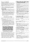
1
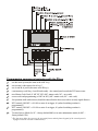
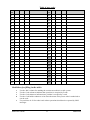
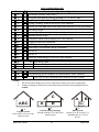
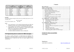
Programming sequences beginning with the ∗ key ∗1 ∗2 ∗3 ∗4 ∗5 ∗6 ∗7 ∗8 sets the entire system (the same as the ABC key) sets section A (the same as the A key) 1) sets A and B, or just B (the same as the B key) 1) event memory recall (key 4 scrolls backwards) – the control panel records the 255 latest events new Master Code/Card (∗5 MC NC NC) (MC- master code; NC – new code) access code/card programming (∗6 MC nn NC) (MC- master code; NC – new code) for operation while under duress (should be entered before the access code to secretly signal distress) PGX control (ON/OFF = ∗81/∗80 or enter ∗8 to trigger, if a pulsed switching reaction is programmed) 1) PGY control (ON/OFF = ∗91/∗90 or enter ∗9 to trigger, if a pulsed switching reaction is programmed) 1) To enter Service Mode (0∗ SC – factory default 8080) or to enter maintenance mode (0∗ MC – factory default 1234) ∗9 ∗0 1 ) The functions allow the system to be operated from a mobile phone keypad (if the control panel is equipped with the relevant communicator). Limited warranty Subject to the conditions of this Limited warranty Jablotron Ltd. warrants this product to be free from defects in design, material and workmanship at the time of its original purchase by a customer for a subsequent period of two (2) years. Should your Product need warranty service, please return it to the dealer from whom it was purchased. Conditions: 1) The warranty is valid only if the original receipt issued to the original purchaser by the dealer, specifying the date of purchase, is presented with the Product to be repaired or replaced. Jablotron reserves the right to refuse warranty service if this information has been removed or changed. 2) This warranty does not cover any failure of the Product due to misuse, including but not limited to use in other than the normal and customary manner, in accordance with instructions for use and maintenance of the Product. Nor does this warranty cover any failure of the product due to accident, modification, adjustment, improper repair or acts of God. 3) This warranty does not apply to batteries nor modules of other suppliers (e.g. SIM card of the GSM provider). 4) The warranty provided does not affect the consumer's statutory rights under applicable national legislation in force, nor the consumer's rights against the dealer arising from their sales/purchase contract. Contents Dear Oasis user ................................................................................................. 2 What is a security system? ............................................................................... 2 System access codes (cards) ............................................................................. 3 1. System setting (arming) .......................................................................... 4 2. During the setting (arming) process … ................................................... 5 3. After the system has just been set (armed) ............................................. 6 4. System unsetting (disarming) ................................................................. 6 5. To stop the alarm .................................................................................... 7 6. Operating the system from an outdoor keypad ....................................... 8 7. Panic alarm ............................................................................................. 8 8. Controlling connected devices from a keypad ........................................ 8 9. Remote control – by phone, Internet....................................................... 9 User configuration – access codes (cards) ....................................................... 9 10. Programming the master code (card) ................................................ 10 11. Programming user codes (cards) ....................................................... 10 12. Key-fob setting ................................................................................. 12 User configuration – Maintenance mode ...................................................... 12 13. Entering Maintenance Mode ............................................................. 12 14. System testing ................................................................................... 12 15. Displaying which user/card positions are occupied .......................... 13 16. Bypassing.......................................................................................... 14 17. Setting the internal clock .................................................................. 14 18. Automatic setting/unsetting schedule ............................................... 15 19. Programming phone numbers for SMS messages ............................ 16 Your Installer: Date: Manufacturer: JABLOTRON ALARMS Inc. Oasis user manual http://www.jablotron.com/ 1 MKE22102 Dear Oasis user The development and production of your security system have been done by the manufacturer with maximum care so that your oasis of safety – your room, house or company premises – can be protected as well as possible. The second party having an impact on the quality of a security system is the installer. The installer company should know the system well, therefore do not hesitate to contact them if you have any questions about system operation or when you need an in-depth explanation of how the system works. However, the most important participant of a properly working security system is you, the daily user. Please, follow these guidelines as well as the installer’s instructions when you take over the system. During the system’s everyday use, you can read information from the keypad display. This way you can be informed that a balcony door is open or that maintenance of a particular device is needed. What is a security system? Any electronic security system (ESS) has a control panel as its essential part. The control panel comprises all the system’s important functions. Among the control panel’s constituent optional parts, there is a communicator for transmitting messages to an alarm receiving centre, and a back-up battery, which ensures that the system works properly (for a given period) after a power supply outage. The control panel should be installed in a hidden place. In the case of an intrusion, a hidden-working control panel transmits messages even if all other parts of the ESS have been destroyed. The connection between you and the control panel is established via a keypad. This way you can operate the system or, conversely, the system informs you via the keypad display or LED signalling. House premises are protected by detectors. These react to various events: movement (PIR), door or window opening (magnetic detector), glass pane breaks (glass break detector). In addition, smoke detection or combustible gas leak detection can be included in a system’s functionality. This way an ESS can detect threats to property or health. When a security system detects movement in a protected area, information is sent, depending on the system configuration, to your mobile phone or to an alarm receiving (central monitoring) company, which performs on-site physical intervention. Outdoor sirens let the neighbourhood know that something is going on, whereas the main purpose of indoor sirens is to discourage the intruder. Oasis user manual 2 MKE22102 The Oasis system is configurable and its exact behaviour is determined by system settings. The following text contains references to the system configuration table which is to be found at the end of this manual. The table should be filled in by an installer during the installation process. References are numbered, like for instance ( 4.). In this case you can find particular settings for the 4th parameter in the table. System access codes (cards) The system status can be controlled via a keypad (internal or external) using access codes or cards. To prevent misuse by a stolen card, you can set that card access must be confirmed by entering a proper code (5.). In addition, you can operate the system wirelessly by key-fob or remotely via phone or using internet access (see www.GSMLink.cz). Access codes and cards Access codes and cards allow system operation – i.e. setting (arming), unsetting (disarming), stopping triggered alarms, triggering silent alarms (PANIC), etc. Access code functionality can be configured during installation. The system allows for up to 50 different access codes (cards) to be assigned to different users. This way it is possible to distinguish (at the alarm receiving centre or in the control panel memory) who has operated the device and when. As a factory default, all access codes are blank. It is up to you – the system administrator (master) – to define access codes as desired, using a Master code or card. Note: Entering an invalid access code ten times in a row will trigger a tamper alarm. The Master code (card) The master code (card) is an access code or card with a higher priority which, in addition to allowing system control, enables you to change or configure access codes for other users. Knowing the master code or possessing a master access card is necessary for any user configuration of the system. Usually, the master code is used by the system owner or administrator, who performs a change of the factory default value 1234 to his or her required master code after taking the system over from the installer. An access card can be set up in place of a master access code. This should be kept in a safe place. Oasis user manual 3 MKE22102 The service code The service code is a special code designed for a service company. The code allows maintenance technicians system configuration and testing. Note: it can be set by a service technician that by means of a service code it is possible to unset the system to provide full service and maintenance of the system under any circumstances (he will not be able to modify or add user codes). Unsetting the system by the service code can only be enabled with the written agreement of the owner of the system – see 15. 1. System setting (arming) There are several ways to set (arm) the system. An unsplit system (1.) • • • Enter a code (present a card). On the key-fob, press the button. If operation without an access code is enabled (4.), you can set (arm) the system by pressing the ABC key. A system with partial setting (arming) (2.) • • • • If operation without an access code is enabled (4.), you only have to press the A button to set section A, the B button to set both sections A and B, or the ABC button to set the entire system. When the system is only partially set (e.g. only section A), it is possible to extend the proportion of the system armed by pressing the corresponding button (B or ABC). All detectors configured to delayed or next-delayed reactions will provide an exit delay. Thus, you will not need to turn off partial setting first to set the whole system each time you leave the house. Instead, you can perform total setting straight away and the system allows departure through all zones covered by delayed and next delayed detectors. If operation without an access code is disabled (4.), then pressing the A, B, or ABC key must always be followed by entering an access code (or by presenting an access card). Key-fob: press for total setting (A + B + C) to set section A press press to set sections A+B Oasis user manual 4 MKE22102 A split system (3.) • • If operation without an access code is enabled (4.), you only have to press the A or B button to set (arm) the corresponding section. Pressing the ABC button results in total setting. If operation without an access code is disabled (4.) and you perform setting (arming) via an access code or card, then only the section assigned to the code (card) is set (A, B or ABC). o If the code (card) belongs to the whole system (ABC), then it is possible to set only section A or B by pressing button A or B before entering the code (card). • • • Using an access code (card) assigned to section C will set the entire system (ABC). You can also set either section A or B alone – by pressing the A or B button respectively before you enter a code (or present a card). button on the key-fob the section to which the By pressing the key-fob belongs will be set. When both sections A and B are set, the common section C is set automatically too 2. During the setting (arming) process … The system will warn you when anything is going wrong. Pay attention at the moment of setting to the information on the keypad. If the (10.) parameter is enabled, then by displaying “Triggered det.” on the keypad, the system gives you notice that a detector is triggered (usually a window or a door is open). By pressing the ? key you will be shown which particular detector it is. If there are more detectors triggered, you can access them on the display by pressing (?) repetitively. Naturally, in such situation, it is appropriate to check through the building and close the doors and/or windows. If the (10.) parameter is disabled, then no “Triggered det.” text will be displayed. Nonetheless, pressing the ? key lets you display the list of triggered detectors. If the (11.) parameter is enabled and “Triggered det.“ is shown on the keypad display, then after entering an access code (card) or after pressing the A B or ABC button for quick setting (arming) you will be offered the possibility of a bypass – which means the temporary removal of triggered zones from the system. If you wish to accept/confirm the bypass suggestion, press *. If no confirmation is made, the system will not be set! The system behaves the same way when bypassing has been pre-programmed in maintenance mode. Oasis user manual 5 MKE22102 If the (11.) parameter is disabled, any triggered detector is bypassed automatically – no key-press confirmation is needed. While setting (arming) the system via a key-fob controller, any triggered zone is bypassed automatically regardless of the (11.) parameter. If a detector has been bypassed, it starts to protect as soon as it is de-triggered (for example, if a door is closed). 3. After the system has just been set (armed) • • • • • • The keypad beeps and an exit delay will begin. The keypad displays “Exit delay”. The keypad indicates which sections have been set (A; B; C). If exit delay acoustic signalling (6.) is enabled, the exit delay is indicated by regular beeps from the keypad (the beeps get faster in the last 5 seconds). For a partially set system, the exit delay may not be signalled acoustically (7.). You have to leave protected areas before the exit delay (20) elapses. If final-door detector mode (12.) is triggered during an exit delay, then the exit delay is extended to the moment when the final door is closed. So you can set and leave the house comfortably without any haste. If the final-door detector is not triggered, then the system provides a normal exit delay. 4. System unsetting (disarming) After you step into a set (armed) section, an entrance delay will begin. This is indicated by displaying “Entrance delay” on the keypad. Also, the keypad starts to beep fast if entrance delay acoustic signalling is enabled (8.) (the wireless keypad only if it is powered from the AC adaptor or the door detector is connected to the keypad or when you open its cover). Additionally, the entrance delay time can be indicated by an indoor siren. • • During the entrance delay ( 21) you have to unset (disarm) the system by entering a valid access code (or, alternatively, presenting a valid access card, or using a valid key-fob). If final-door detector mode (12.) is active and you came in through the corresponding door, then the entrance delay would be six times longer than if it had been triggered by an ordinary detector (i.e. if you Oasis user manual 6 MKE22102 had come in through a “main door”). This way you have enough time for unsetting the system ( 22). However if any other delayed detector is activated the entrance delay will be shortened to a normal entrance delay time. If the is flashing on the keypad and the display is showing which device was triggered, it means that there was an alarm. Unset the system and carefully check the reason for the alarm. Keep in mind that there could be somebody hidden on the premises. Alarm memory – can be erased from the display by pressing button # flashing - • An unsplit system (1.) • • Enter a code (present a card). Use a key-fob: by pressing the whole system. (or ) button you will unset the A system with partial setting (arming) (2.) • • Enter a code (present a card). Use a key-fob: By pressing the whole system. (or ) button you will unset the A split system (3.) • Enter a code (present a card) or use a key-fob to unset the corresponding system section. 5. To stop the alarm If there is an alarm in the system it can be stopped by entering a code on the key-fob). (presenting a card or using a Alarm signalling – a flashing and information about the reason for the alarm – this can be terminated (after stopping the alarm) by pressing the # button. The memory entry for the last alarm can be displayed by pressing ∗4, to scroll through the history keep pressing button 4. Keep in mind that there could be somebody hidden on the premises. If you have any doubts, then it is recommended to have the premises checked by a security service from the alarm receiving station. Oasis user manual 7 MKE22102 6. Operating the system from an outdoor keypad If the system is equipped with a JA-80H outdoor keypad or a JA-80N external card reader, then the outdoor device can be set to work the same way as an indoor keypad. The system will be set/unset after entering a code (presenting a card). A more common usage of the outdoor keypad is to open the entrance door: • Performing setting or unsetting the system is only possible via an indoor keypad (or via a key-fob controller). • Enter a valid access code or present a valid card to the outdoor keypad to open the electronic door lock. If the system is set, and the door is opened via an outdoor keypad, an entrance delay will begin. During this delay period the system has to be unset using an indoor keypad unit (or a key-fob). 7. Panic alarm If you are in danger you can trigger a silent panic alarm to inconspicuously call for help. After triggering a panic alarm the system will send voice messages, SMS messages, and pass data to an alarm receiving centre (central monitoring station), depending on installation settings. A set system will be unset. A panic alarm can be triggered as follows: • • • • On the keypad – enter * 7 before entering an access code (before presenting a card). If the system has been in a set state, it will be unset = operation under duress. and buttons simultaneously. On the key-fob controller – press both If desired, the controller can be re-configured (by an installer) for Panic Mode, in which pressing any button will trigger the Panic alarm. By pressing a large-sized panic button (that can be installed on a wall, under a desk etc.). By a panic code or card on the keypad. 8. Controlling connected devices from a keypad The control panel allows you to control various devices in the building, e.g. heating, air conditioners, ... (13.) and (14.). Control can be performed via a keypad by keying-in the following: Oasis user manual 8 MKE22102 Device X (13.) turn ON turn OFF Device Y (14.) turn ON turn OFF * 81 * 80 * 91 * 90 The outputs may be used to unlock locks – opening a door via a short impulse). In this case, enter the following: an impulse to operate (13.) is provided by pressing * 8 an impulse to operate (14.) is provided by pressing * 9 Optionally, the system can be pre-programmed by a service company so that the above operations require an access code (card). 9. Remote control – by phone, Internet If the control panel is equipped with a suitable communicator (C.) you can control it remotely by mobile phone (directly by using the phone’s keypad or by SMS). It can be also controlled via the Internet – after registration on www.GSMLink.cz For further details see also the communicator’s manual. User configuration – access codes (cards) The following description is intended for a system administrator, who knows the control panel master code or possesses a master card which is authorized to modify the system configuration. All the settings can be performed via keying-in on a system keypad (or very comfortably via a PC running Olink software). An unfinished sequence can be cancelled by pressing the # key. A sequence is stored into control panel memory only after the sequence has been completely entered. Note: The Oasis JA-80 system has three modes: operating mode, maintenance mode and service mode. Operating mode is for the day-to-day use of the system by all authorized users, e.g. setting/unsetting (arming/disarming). Maintenance mode is for the holder of the master code (system administrator) to have limited programming of the system, e.g. changing codes/cards, bypassing and is inaccessible to all other users. Service mode is only for installers and is used to program and control all aspects of the system. Oasis user manual 9 MKE22102 10. Programming the master code (card) The master code is used by the house owner or administrator (supervisor). The factory default setting is 1234. The administrator should program his/her own four-digit code while taking the system over from an installer. This prevents other parties from accessing the system configuration. Master code programming is only possible when the system is unset (disarmed) and not in maintenance mode. To change an existing master code enter: * 5 xxxx yyyy yyyy where xxxx is the existing master code yyyy is the new master code (the new code must be entered twice to avoid errors). Combination 0000 cannot be used. The master code cannot be erased. Example: Existing code 1234 will change to 6723 by entering: * 5 1234 6723 6723 If you wish to use an access card instead of a code, you can enter * 5 xxxx and then present the card. This makes the card authorized for system configuration. If you forget the master code (or if you lose the card), an installer can reset the code to the factory default setting 1234 (this requires the system to be unset (disarmed). All other pre-programmed codes (cards) in the system remain unaffected. 11. Programming user codes (cards) The system allows for up to 50 different access codes (cards). Their modification or deletion is only available to the system administrator who knows the master code. The most comfortable way to edit the user code is via Olink software. Code programming is only possible when the system is unset (disarmed) and not in maintenance mode. In practice, it is convenient that each user has his own user code preprogrammed. The system stores to its memory which code was used for what Oasis user manual 10 MKE22102 event and when. As a factory default, all access codes (cards) are blank. To define a user code, enter the following sequence: * 6 xxxx nn yyyy where xxxx is the master code nn is the user code index (from 01 to 50) yyyy is the new user code. By inserting 0000 the code in the nn position will be erased Example: If the master code is 1234 and user 3’s new code should be 5277, enter: * 6 1234 03 5277 Alternatively, assign a card to user 3 by entering: * 6 1234 03 and present user 3’s card Notes: • Both a code and a card can be assigned to every position • If you want to assign a code and a card to position nn set the code and then on the same position the card (or vice versa) • If the system is programmed to require card verification by code (5.), a user who has a code and card set always uses both (no matter which order). If the user has only a code or a card then verification does not concern him. • If the administrator records the codes on the table in the appendix of this manual it is necessary to keep it hidden in a safe place. Better would be to use and store them in the Olink software (access is encrypted).. • The installer sets the reaction of the system to each code and the code assignments to each section (A,B,C). • A code cannot be assigned to 2 different positions. Code relocation can be done by deleting the code (card) and, subsequently, programming it to a new position. • For security reasons, do not use codes which are easily predictable such as four equal digits, birth dates, company personal numbers, etc. • The administrator can check which positions (01 to 50) are occupied by a code or card in maintenance mode – see 15. • To erase a code without knowing its nn position use sequence ∗ 6 master code (card) 00 code • To erase all codes and cards set ∗ 6 master code (card) 00 0000. The master code (card) will not be effected. Oasis user manual 11 MKE22102 12. Key-fob setting Setting or adding other key-fobs to the system can be done by the installer who is also able to block or replace a lost key-fob. An immediate bypass can be done by the administrator of the system - see 16). User configuration – Maintenance mode The following description is intended for a system administrator, who knows the control panel master code or possesses a master card which is authorized to modify the system configuration. All the settings can be performed via keying-in on a system keypad. An unfinished sequence can be escaped from by pressing the # key. A sequence is stored into control panel memory only after the sequence has been completely entered. 13. Entering Maintenance Mode You can enter maintenance mode when the control panel is unset by keyingin * 0 master code (card). The mode will be indicated on the keypad display. Maintenance mode enables the following: • internal-clock configuration • automatic setting/unsetting schedule • programming telephone numbers for alarm reporting • testing detectors or opening their covers without triggering an alarm • zone bypassing configuration • displaying which code/card positions are already occupied Exit maintenance mode by pressing the # key. 14. System testing The administrator should test the system monthly. For testing, the control panel should be in operating mode and unset (it can also be in maintenance mode). When in operating mode, the control panel indicates the triggering of a detector, but no alarm can be triggered if the system is unset. We recommend triggering the detectors (zones) one by one and verifying that the triggering is indicated on the keypad display – by displaying the signal type and source. Remote controllers (key-fobs) or panic buttons can be tested in a similar way. Oasis user manual 12 MKE22102 Note: some detectors (for example the JA-83P wireless motion detector) are equipped with battery-saving functionality which prevents repetitive triggering in short intervals. In this case a pre-programmed time has to elapse before subsequent triggering is possible (up to 5 minutes). In maintenance mode, close the wireless keypad’s flip cover if you are not working with it to save battery energy. If anything does not work properly during testing, call the installer for help. In maintenance mode it is possible to replace discharged batteries in the devices. But it is highly recommended to ask your installer to replace the battery. Improper handling can result in damaging the device and loss of warranty. Recommendations: the system should be annually inspected by a professional installer who should check the backup battery voltage and perform functionality testing. 15. Displaying which user/card positions are occupied When in maintenance mode, the control panel can display which positions in the range 01 to 50 are occupied by codes or cards. To display the positions: • • • Press key 5 (the display indicates “Codes 01: Code” – or the name of the code holder). and all user positions (01 to 50) can be Using the arrow keys scrolled through. The A indicator shows whether a code is programmed or not, and the B indicator shows whether a card is programmed or not. (This means if both indicators are lit, the position is occupied by a code and a card.) To exit this code/card display mode press the # key. Notes: Oasis user manual 13 MKE22102 • • Code programming is only possible when the system is unset (disarmed) and in Operating mode. When the system is in Maintenance mode, code programming is disabled. The most convenient way to administer codes is by using a PC running Olink software – select the “Codes” menu option. 16. Bypassing In practice, you may need to set (arm) the system while excluding particular zones (potential sources of alarms). This exclusion is referred to as a bypass. To set up a bypass: 1. 2. 3. 4. Press key 1 to open the bypass menu while in maintenance mode. and keys, you can scroll through all potential alarm Using the sources. Select the source (detector, controller…) which you want to bypass and: a. press key 2 to bypass the source for the next setting/unsetting indicator will start flashing), cycle (the b. press key 3 to bypass the source permanently (the indicator will light continuously). c. Multiple pressing and holding of the keys (2 or 3) will toggle the bypass on – off – on … d. Using key 4 will cancel all device bypasses in the system. All the desired bypasses can be reprogrammed by repeating step 2. Press the # key to exit the bypass menu. Pressing # again exits maintenance mode. Notes: • If a system with bypassed devices is being set, then bypass text will be displayed on the keypad unit. • Any bypass programmed for a single setting/unsetting cycle will be automatically cancelled after unsetting (disarming) the system. • The existing bypass configuration can be checked or modified in the bypass menu. • If the installer enters service mode all bypasses will be cancelled.. Alternatively, you can cancel all bypasses using key 4 in the bypass menu. 17. Setting the internal clock The control panel has a built in real-time clock which is used to time-stamp all recorded events in the control panel memory. The clock should be set during installation. However, the administrator can re-set the clock. This can be used Oasis user manual 14 MKE22102 for summer time offsets when automatic summer time is disabled ( A.). To set the clock, enter: 4 hh mm DD MM YY where: hh mm DD MM YY hours minutes day month year Example: at 21:30 on April 29, 2007 enter: 4 21 30 29 04 07 If automatic summer time is enabled ( A.), the control panel’s internal clock is automatically offset by +1 hour on March 31st at midnight. The offset is then removed on October 31st at midnight to return to winter time. 18. Automatic setting/unsetting schedule This can be used to program an automatic sequence of daily setting/unsetting events. Up to 10 daily events can be programmed. The events will occur every day of the week. To program an automatic schedule enter: 64 n a hh mm where: n a hh mm is the event number from 0 to 9 is the type of event from 0 to 6 (see the following table) hours (time of event) minutes (time of event) ( 1.) Unsplit system a 0 1 2 3 4 5 6 No event Set all Unset all Set all Set all Unset all Unset all Oasis user manual ( 2.) Partially split system No event Set all Unset all Set A Set AB Unset all Unset all 15 ( 3.) Split system No event Set all Unset all Set A Set B Unset A Unset B MKE22102 Example: To program setting (arming) the AB section of a partially split system at 22:45 everyday, enter: 64 0 4 22 45 To cancel the schedule, enter: 64 0 0 Notes: • If the control panel is in the requested setting/unsetting state before the scheduled event time, the event will not change the setting/unsetting. • If any automatic event is selected, it will be performed everyday at the programmed time with all its consequences. It means that the system will be set even when people are still on the premises, • To cancel a scheduled event, enter 64 n 0 • As a factory default, all automatic events are switched off. 19. Programming phone numbers for SMS messages This setting is usually performed by an installer during the installation. The programming of the phone numbers can be also done by the administrator in Maintenance mode if enabled ( B.). Follow the manual supplied with the communicator. Oasis user manual 16 MKE22102 Table of user codes Posi ABC tion Code Card Code holder Posit ABC ion 1. 26. 2. 27. 3. 28. 4. 29. 5. 30. 6. 31. 7. 32. 8. 33. 9. 34. 10. 35. 11. 36. 12. 37. 13. 38. 14. 39. 15. 40. 16. 41. 17. 42. 18. 43. 19. 44. 20. 45. 21. 46. 22. 47. 23. 48. 24. 49. 25. 50. Code Card Code holder Guidelines for filling in the table: • • • • • Use the ABC column for marking the sections accessible in a split system Use the Code column to indicate that a position is occupied by a code Use the Card column to indicate that a position is occupied by a card Use the Code holder column to write down the name of the person who is authorized to use the code Use positions 41-50 for codes/cards whose operations should not be reported by SMS messages. Oasis user manual 17 MKE22102 Oasis configuration table No. 1. 2. 3. 4. 5. 6. 7. 8. 9. 10. 11. 12. 13. 14. 15. Oasis control panel configuration An unsplit system (only ABC) A system with partial setting (arming) (A or AB or ABC) A split system (A or B or ABC) Setting (arming) without an access code enabled Access by code and card (both card and code have to be presented) Exit delay beeps Exit delay beeps while partially setting (arming) Entrance delay beeps Permanent alarm status display for a set system Triggered detector indication Auto-bypass of triggered detectors Final-door (exit/entrance delay extended) Device X: Device Y: Unsetting (disarming) by service code enabled 20. 21. 22. sec Exit delay time sec Entrance delay time for a “main-door” access sec Entrance delay time for a “final-door” access A. B. C. Automatic summer time Programming phone numbers in maintenance mode enabled The type of the communicator installed in the system Notes: • • The table should be filled in by a service technician according to the system configuration Ticking (checking) the field in the second column indicates that the corresponding function is enabled C ABC 1. Unsplit system Only allows you to set the entire system Oasis user manual A B 2. Partial setting (arming) Setting (arming) A or AB or the entire system 18 A B C 3. Split system Setting A or B. Section C is automatically set if A+B are set. MKE22102 Table of device positions Positi ABC on Type Location / User Positi ABC on 1. 26. 2. 27. 3. 28. 4. 29. 5. 30. 6. 31. 7. 32. 8. 33. 9. 34. 10. 35. 11. 36. 12. 37. 13. 38. 14. 39. 15. 40. 16. 41. 17. 42. 18. 43. 19. 44. 20. 45. 21. 46. 22. 47. 23. 48. 24. 49. 25 50. Type Location / User Guidelines for filling in the table: • • • • • The table should be filled in by a service technician according to the system configuration (composition). Use the ABC column to indicate which section a device falls into. Use the Type column for device type specification (e.g. JA-83P, JA-83M, RC-86, …). Use the Location/User column to describe where a detector is located (a porch, living room,…) or to write down the user of a remote controller (Uncle Charles, Aunt Mary). The table can be also printed out in the Olink software. Oasis user manual 19 MKE22102