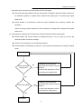
1
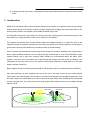
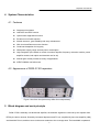
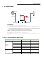
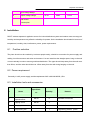
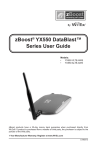
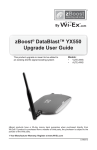
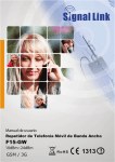
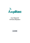
Digital Repeater
DS30-37-5S
Repeater User Manual
1
Safety Warnings _____________________________________________________________________ 3
2
Why repeater ________________________________________________________________________ 3
2.1
Reason__________________________________________________________________ 3
3
Introduction_________________________________________________________________________ 4
4
System Characteristics ______________________________________________________________ 5
4.1
Features _________________________________________________________________ 5
4.2
Appearance of DS30-37-5S repeaters __________________________________________ 5
5
Block diagram and work principle ____________________________________________________ 5
6
The repeater system _________________________________________________________________ 7
7
DS30-37-5S Main technical specification ______________________________________________ 7
7.1
8
Requirements for adapters: _________________________________________________ 8
Installation __________________________________________________________________________ 9
8.1
Position selection __________________________________________________________ 9
8.2
Power requirement _________________________________________________________ 9
8.3
Installation tools and accessories______________________________________________ 9
8.4
Chassis installation _______________________________________________________ 10
8.5
Repeater’s ports description ________________________________________________ 12
8.6
Accessories selection______________________________________________________ 12
8.7
Repeater Settings ________________________________________________________ 12
8.7.1
Switch on power ______________________________________________________________________ 13
8.7.2
Parameters setting ____________________________________________________________________ 14
8.7.3
Repeater Commissioning _______________________________________________________________ 14
8.8
System Test _____________________________________________________________ 15
8.8.1
Check whether the coverage is good ______________________________________________________ 15
8.8.2
Repeater can not communicate in Power-ON status __________________________________________ 17
Preface
This user’s manual describes the installation, commissioning and maintenance of
DS30-37-5S
repeaters. Please do read the user manual carefully before installing and maintaining
DS30-37-5S repeaters. The information in this manual is subject to change without prior
notice.
Opinions are welcomed about the manual improvement.
-2-
Repeater User Manual
1 Safety Warnings
Users must follow the below principles:
l
Repeater should follow system requirement of communication equipment, assure good
groundings and lightning protection.
l
The power supply voltage of repeater should meet the standards of security
requirement; any operation shall be carried out only after cutting off power in advance.
Only the professional is authorized for the operation.
l
Do not dismantle machine, maintain or displace accessories by yourself, because in
this way, the equipment may be damaged or even get an electric shock.
l
Do not open the repeater; touch the module of repeater, or to open the cover of module
to touch the electronic component, the components will be damaged due to electrostatic.
l
Please keep away from heating-equipment, because the repeater will dissipate heat
during operation. And do not cover booster with anything that influences
heat-dissipation.
2 Why repeater
2.1 Reason
1) Blind or weak signal areas are formed if the buildings are too far away from BTS, or the buildings
themselves shield or absorb the signals.
2) There are too many complicated signals in the higher part of the buildings, therefore ping-pong
switching effect has been formed and the signals fluctuate a lot, there are annoying noises during
phone calls and there are dropped phone calls accordingly.
3) Elevators and basements are well-known blind areas.
-3-
Repeater User Manual
4) Downtown areas of the cities, congested with many high-rise buildings are usually the weak or blind
areas.
3 Introduction
DS30-37-5S full duplex mobile communications repeater from Huaptec is the perfect solution for providing a
wireless improvement in the cellular reception of large building like shopping mall, commercial office in the
quickest time possible. One repeater covers 40000 to 80000 square feet.
It is designed to improve the call quality of an area by receiving, amplifying and re-transmitting signals of the
base station into a specified area via the server antenna of the repeater.
This repeater has Manual Gain Control (MGC) feature that enables engineers to reduce the gain of the
repeater manually if oscillation is detected or too strong input power level during installation, this will help to
get the best coverage effect without any interference back to mobile network.
And to maintain safe and specific output signal levels during the repeater’s operation, this repeater has a
built-in signal oscillation detection circuit to adjust the gain automatically so as to avoid interference to the
cellular network, also it gets color changing LED’s indicate its environmental status: the Alarm LED’s
located on the front of the unit (Alarm Low & Alarm High) will change color from green to orange or red,
(depending on the input power level) if the system detects signal oscillation in either band or, if the input
signal is beyond a safe limit.
Below diagram shows how simple and fast DS30-37-5S repeater system is installed and works effectively.
One donor antenna, has been installed at the top of the roof or the tower to pick up good mobile signals
from outside, and send through a 5D-FB cable to a DS30-37-5S repeater to be amplified significantly, then
the output signals are transmitted to the server antenna through cables, after amplifying then transmitted
into the coverage area. Very clear phone call or high speed mobile data services are immediately affected
within the area.
Donor ant.
Server ant.
repeater
Base station coverage area
Repeater coverage
-4-
Repeater User Manual
4 System Characteristics
4.1 Features
l
Support quint systems
l
Has MGC and AGC function
l
Uplink noise suppression function
l
Excellent out of band rejection
l
Module structure, good reliability and easy maintenance
l
With Local and Remote monitor function
l
Good heat dissipation for longevity
l
Wide power supply range and low power consumption
l
High-integration (One board to contain low-noise amplifier, frequency selection module, power
amplifier module, both uplink and downlink one for all)
l
Manual gain control provides a variety of applications
l MTBF>50000h, low failure rate
4.2 Appearance of DS30-37-5S repeaters
Figure 1 the front view (colors may differ from real products).
5 Block diagram and work principle
DS30-37-5S is basically a bi-directional amplifier, the downlink signals are received by the repeater from
BTS by the donor antenna, filtered by its internal duplexers and FC unit, amplified by low noise amplifier (LNA)
and downlink PA unit, and then sent via the server antenna to the coverage area. The bandwidth is operators’
-5-
Repeater User Manual
working frequency only.
The uplink signal of mobile terminal from the coverage area is input via the server antenna, then filtered
by duplexers and FC unit, amplified by the uplink low noise amplifier (LNA) and the uplink PA unit and finally
sent via the donor antenna to the BTS.
Modules in the system diagram:
l Combiner:The main purpose of combiner is to combine quint system to share the same
antennas.
l Duplexer: The main purpose of duplexer is to combine downlink and uplink to share the same
antennas, the duplexer is composted of one pair of band pass filter that can not only reject the
spurious interference, but also increase the isolation of Uplink and Downlink.
l LNA: LNA is the first active sub system of the repeater, of which low noise and high linearity is
requested under strong input signals. LNA is the major sub system that determines the noise
figure of the repeater system.
l FPGA: Field-Programmable Gate Array, to process the digital signal transferred from analog
signal.
l PA: The power amplifier sub system helps the repeater to reach its targeted output power,
linearity of which decides the linearity of the repeater.
l Power supply is to supply power electricity to all repeaters’ modules.
-6-
Repeater User Manual
6 The repeater system
Server ant.
Donor ant.
Coaxial cable
Repeater
Coaxial cable
AC Power
BTS MS
Lightning arrester
Lightning arrester
Jumper cables
l Donor Antenna:
Ø Parabolic antenna is recommended as donor antenna.
Ø Function: Pick up donor signals from the BTS and send to the repeater by cable; the
received signals’ power level and quality influence a lot on the coverage effect. Donor
antenna also transmits the uplink signals from the repeater to BTS.
l Cables: LMR 300 or 400, 5D or 8D FB coax cables are recommended.
l Server Antenna:10-12dBi outdoor panel are recommended
l Power Box including electricity meter, air switch and groundings, some sites might need surge
arrestors.
7
DS30-37-5S Main technical specification
Electrical specification
Frequency
Range
Max. Gain
Uplink
Downlink
CELL
824 ~ 849MHz
869 ~ 894MHz
PCS
1850 ~ 1910MHz
1930 ~ 1990MHz
AWS
1710 ~ 1755MHz
2110 ~ 2155MHz
LTE(A+B)
704 ~ 716 MHz
734 ~ 746 MHz
LTE C
776 ~ 787MHz
746 ~ 757 MHz
DS30
≥ 75dB
≥ 80dB
DS33
≥ 80dB
≥ 83dB
DS37
≥ 83dB
≥ 87dB
-7-
Repeater User Manual
Max.
Output
power
Band width
DS30
≥ 20dBm
≥ 30dBm
DS33
≥ 20dBm
≥ 33dBm
DS37
≥ 25dBm
≥ 37dBm
CELL
available upon request
PCS
available upon request
AWS
available upon request
LTE(A+B)
18MHz
LTE C
11MHz
MGC (Step Attenuation)
≧31dB / 1dB step by step software setting
Automatic Level Control
≥ 30dB, Auto Gain Setting
Gain Flatness
Typ
≤ 3~6dB (p-p) as per sub-band
AWS
≤ 2dB/ 3.84MHz
Noise Figure
Typical≤ 8dB
VSWR
Typical≤ 2
Group Delay
Typical≤ 8μs
Frequency stability
≤0.01ppm
Mechanical Specifications
Standard
I/O Port
N-Female
Impedance
50 ohm
Operating Temperature
-25ºC~+55ºC
Environment Conditions
IP40
Dimensions
19*9.8 *4.6inch/483*250*116mm
Weight
≤22lbs/10KG
Power Supply
Input AC90~264V
7.1 Requirements for adapters:
SN
Item
Minimum
-8-
Typical
value
Maximum
Repeater User Manual
1
Input Voltage Range
90 V
220 V
264 V
2
Output Voltage Range
47 Hz
50Hz
63 Hz
3
Total Power
60W
Consumption
8 Installation
DS37T wireless repeater is applied to source for indoor distribution system and outdoor areas coverage, air
humidity and temperature may affect the reliability of repeater. So the installation should take full account of
temperature, humidity, dust, interference, power, space requirements.
8.1
Position selection
The place should not be reached by irrelevant people easily, should be convenient for power supply and
cabling. Avoid heat source and moist environment. You can install it at the draught space; hang on the wall
or mast vertically in order to assure good heat distribution. The upper should keep away from the wall more
than 50cm, and the under should be over 100cm away from the wall during hanging on the wall.
8.2 Power requirement
Generally it is AC power supply, and the requirement of AC is 90~264VAC/50±5Hz.
8.3 Installation tools and accessories
N
Specificati
o
Name
Quantity
Remark
on
.
1
Plastic
Expansion Bolt
M5*24
6
Standard accessories
2
Tapping screw
M3*30
4
Standard accessories
3
Hanging folder
1
Standard accessories
4
reciprocating drill
1
Engineering-owned, punch
-9-
Repeater User Manual
the wall
5
Shot bit
M3
1
Engineering-owned, punch
the wall
8.4 Chassis installation
a. Installation on the wall
l Installation dimension
l Installation block diagram
l Installation procedure:
1) According to 300*460mm back shelf installation position, drill 4 *M8 holes on the wall,
assembly 4 pieces expansion screws.
- 10 -
Repeater User Manual
2) Put the rack onto the 4 expansion screws, to fix it on the wall with nuts.
3) The repeater hang along the bayonet on mounting bracket, then install two hex screws
through the holes from mounting bracket and fixing nut rod of host, tightening screws and fix
the host onto the mounting bracket.
4) Ensure the firm and correct installation.
b. Mast installation
l Rod diameter: 3.5-6 inch.
l Modify the rack according to The following chart
l Fasten the rack tightly to the vertical rod
l Installation procedure:
1) Tighten the clamp with bolt on the mast or pole.
2) Fix the bracket on the clamp with 6 pcs expansion M8×80 screws.
3) The repeater hang along the bayonet on mounting bracket, then install two hex screws
through the holes from mounting bracket and fixing nut rod of host, tightening screws and fix
- 11 -
Repeater User Manual
the host onto the mounting bracket.
4) Ensure the firm and correct installation.
8.5 Repeater’s ports description
1)
BTS port: connected with the BTS sector by cable.
2)
MS port: connected with server antenna directly or by cable.
3)
AC IN: connected with power supply.
BTS Port
MS Port
AC IN Port
8.6
Accessories selection
Please pay attention to the two points of “frequency” and “impedance” during the selection of the
accessories. All accessories shall support the repeater’s frequencies from feeder line, antenna and splitter
to combiners etc. For example, the repeater’s frequency is GSM900, so all the accessories must support
the GSM900 frequency. And the repeater’s impedance is 50ohm, so the accessories shall all be 50ohm. To
use any other impedance of coax will put an extra load on your repeater, shorten its life span and decrease
the system performance.
8.7 Repeater Settings
Please check very carefully all cable connections are correct and firm before running operation test and
then carry out following tests
- 12 -
Repeater User Manual
8.7.1 Switch on power
After power is on, check firstly the alarm and power LED.
l
l
Status and definition of POWER indicators:
Status
Definition
Green
Normal
Off
DC power problem
Status and Definition of ALARM indicators,
Status
ALARM
It is working in linearity
Green
Warning: Input signals may be not enough, so please check on coverage
effect, do not do anything if it is good; otherwise please check the donor
antenna position.
There are strong input signals or severe self oscillation. The status can
Red
only maintain 5 seconds with auto shut off function. Please check the
troubleshooting or FAQ to get solutions.
A little bit stronger input signals or slight self oscillation have occurred.
Orange
Solution: Please adjust antennas or slowly add the loss by MGC till the
indicator turning to green. Stop immediately when the color changes
which can provide the best coverage.
Booster breaks down, or severe self oscillation leads to auto mute. Please
Off
re-plug in and check if alarm LED turns red, if it is, please take same
measures like above; if it maintains off which means the power breaks
down.
- 13 -
Repeater User Manual
8.7.2 Parameters setting
Parameters setting refer to OMT in detail
8.7.3 Repeater Commissioning
l The curve about device working status
POutput Power
Critical stable
Pmax
point
(Pinput Power-VATT)
Green LED
Orange LED
Red
linear
Stable work
Equipment
LED
Output power, input signal and their
- 14 -
attenuation curve
Repeater User Manual
POutput Power: Output Power
Pinput Power: Input Power
VATT: Attenuation value of attenuator
Pinput Power -VATT: Input Power-Attenuation value of attenuator
Pmax: Rate output power
l Setting of “edge point”:
Switch on the power supply after connection with donor antenna and server antenna, and
observe ALARM LED.
n If it shines “orange”, use 1dB as step to reduce the gain until “green” turns on, then increase the
gain 1~3dB attenuation value until “orange” starts to turn on, then brings back 1~2dB till “green” is
on, then fix the gain and the repeater’s downlink output power reaches the perfect status.
n If it shines “green”, then:
u To check whether the attenuation value has been set, if it is, use 1dB as step to increase gain
until the “orange” turns on, then brings back 1~2dB till “green” is on again , then the repeater’s
downlink output power reaches the perfect status.
u But if attenuation is not set, it indicates that the input power is not enough.
²
Then please check coverage effect first, if the coverage effect is good, the engineering has
reached expecting target.
²
But if the coverage effect is not good, the donor antenna should be adjusted to get a
stronger signal until “orange” intends to turn on or the effect reaches the target. At this
stage, please make sure “Orange” color is not generated by self oscillation. Please take off
the server antenna to test if it is self oscillation or not: if the Orange turns to be Orange, it
is self oscillation; if it stays as Orange, it is not self oscillation.
l Uplink gain setting
Standard: uplink attenuation values =downlink attenuation values
Remark: Keep in mind that you do not want to have more than a 5dB difference between the uplink
and downlink values for optimum system performance, and it is better to keep the same attenuation
value of Uplink with that of Downlink.
8.8 System Test
8.8.1 Check whether the coverage is good
1) Have a test with mobile phone or data card (engineering mobile phone is preferred). If the signals in
- 15 -
Repeater User Manual
most areas have not been improved, please check below again:
u The weak input signal leads to the low output power. Change the direction of donor antenna or
Its installation position or replace donor antenna with higher gain to increase input signal
power level.
u Check whether it is necessary to add more server antennas due to barriers, whether the
repeater’s
Power is enough; please install more server antennas or change with a repeater with higher
power level.
2) If the signals in small part of the areas have not been improved, please check below:
u Check whether the service antenna is installed correctly or not, you may try to move the
antenna location to improve coverage.
u Check if it is necessary to use a directional antenna.
u Check whether it is necessary to add one or more antenna to enhance the coverage of special
areas.
Test coverage
Check the signal
strength is fit
No
1) Mobility Service antenna
2) increase the number of service
antenna
3) reduce the attenuation values
4) increase the output power
Yes
Check call quality
No
1) Mobility Service antenna
2) increase the number of service
antenna
3) reduce the attenuation values
4) increase the output power
Yes
Completion
- 16 -
Repeater User Manual
u Remark:
²
Reduce the attenuation values---at the same time must ensure the isolation.
²
Increase the output power ---recommended ways: adjust the donor antenna;
increased input signal strength.
8.8.2 Repeater can not communicate in Power-ON status
The power is on but there is signal fluctuation
1) The power is on but it has a signal fluctuation or a flash signal. The phone call can not achieve.
It shall be caused by the insufficient isolation between donor antenna and server antenna.
Please take below measures:
Ø Firstly check whether the alarm LED becomes red. The red light shows the insufficient
isolation.
Ø Secondly adjust the antenna directions or locations or enlarge the distance between them.
Ø Thirdly reduce the repeater’s gain by ATT DIP if the above methods don’t work.
The best minimum distance between donor antenna and serve antenna should be more than
10 meters.
The following measures can also be tried:
Ø Use the roof of the building to enlarge the isolation (Please try to place the donor antenna and
server antenna in different floors).
Ø Use some obstacles.(Such as wall ).
2) The repeater’s power is on but the phone is not connected into the network and still can not
communicate.
Ø Reason 1: There are loose or wrong connections in the repeater system.
² Solution: Please try to fasten the connections between the different parts of the system.
Ø Reason 2: The signals received by donor antenna of other operators nearby are too strong.
(For example, the other operators’ signals are 10 dB stronger than the needed signals.)
² Solution 1: Change the direction of donor antenna or its installation position, so that the
gap of signal strength between operators is reduced.
² Solution 2: Use barriers (like buildings) to block signals of other operators.
- 17 -
Repeater User Manual
- 18 -