1
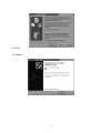
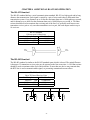
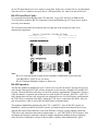
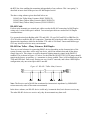
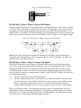
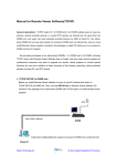
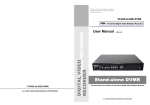
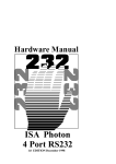
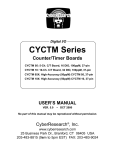
Serial Communications Boards
CYB 1422C
Single-Port PCMCIA RS-422/485
Serial Card
USER’S MANUAL
REVISION 1 – NOVEMBER 2000
(1.11 7/99)
No part of this manual may be reproduced without permission.
CyberResearch, Inc.
www.cyberresearch.com
25 Business Park Drive, Branford, CT 06405 USA
203-483-8815 (9am to 5pm EST) FAX: 203-483-9024
©1994 CBI ©1997 CyberResearch, Inc.
©Copyright 2000 CyberResearch, Inc.
All Rights Reserved.
The information in this document is subject to change without prior noticed in order to improve
reliability, design, and function and does not represent a commitment on the part of
CyberResearch, Inc.
In no event will CyberResearch, Inc. be liable for direct, indirect, special, incidental, or
consequential damages arising out of the use or inability to use the product or documentation, even if
advised of the possibility of such damages.
This document contains proprietary information protected by copyright. All rights are reserved. No
part of this manual may be reproduced by any mechanical, electronic, or other means in any form
without prior written permission of CyberResearch, Inc.
TRADEMARKS
“CyberResearch” and “CYB 1422C” are trademarks of CyberResearch, Inc. Other product names
mentioned herein are used for identification purposes only and may be trademarks and/or registered
trademarks of their respective companies.
NOTICE
CyberResearch, Inc. does not authorize any CyberResearch product for use in life support systems,
medical equipment and/or devices without the written approval of the President of CyberResearch,
Inc. Life support devices and systems are devices or systems which are intended for surgical
implantation into the body, OR support sustain life and whose failure to perform can be reasonably
expected to result in injury. Other medical equipment includes devices used for monitoring, data
acquisition, modification, or notification purposes in relation to life support, life sustaining, or
components required, are not subject to the testing required, and are not submitted to and diagnosis
of humans.
Table Of Contents
CHAPTER 1 HARDWARE GUIDE ................................................................................1
Introduction...............................................................................................................1
PCMCIA 1 Port RS-422/485 Card Features...............................................................1
Configuring PCMCIA Cards. ....................................................................................1
CHAPTER 2 INSTALLING IN YOUR COMPUTER ....................................................2
CHAPTER 3 SOFTWARE INSTALLATION ...............................................................3
Introduction...............................................................................................................3
Windows 95 Installation............................................................................................3
Windows 95 CD-ROM Installation Procedure...........................................................4
Windows 95 Floppy Disk Installation Procedure .......................................................6
Windows 98 and Windows Millennium Installation ..................................................7
Windows 98 CD ROM Installation Procedure ...........................................................8
Windows 98 Floppy Installation Procedure .............................................................10
PCMCIA Card Setup in Win 95, Win 98 and Win Millennium................................12
PCMCIA Port Setup in Win 95, Win 98 and Win Millennium.................................13
Windows 2000 Installation ......................................................................................16
Windows 2000 CD-ROM Installation Procedure .....................................................17
Windows 2000 Floppy Installation Procedure..........................................................20
PCMCIA Port Setup in Windows 2000 ...................................................................22
Windows NT4 Installation.......................................................................................24
Windows CE Installation.........................................................................................26
CHAPTER 4 ADDITIONAL RS-422/485 OPERATION .............................................29
The RS-422 Standard. .............................................................................................29
The RS-485 Standard. .............................................................................................29
Terminating Impedances. ........................................................................................30
Failsafe Open Circuit Detection...............................................................................30
Failsafe Short Circuit Protection..............................................................................30
RS-422 Operation....................................................................................................30
RS-422 Serial Port Cables. ......................................................................................31
RS-485 Operation....................................................................................................31
RS-485 Cable. .........................................................................................................32
RS-485 One Talker - Many Listeners, Half Duplex. ................................................32
RS-485 Many Talkers- Many Listeners, Half Duplex. .............................................33
RS-485 Many Talkers- Many Listeners, Full Duplex...............................................33
Optional Grounding Arrangements..........................................................................35
CHAPTER 1 HARDWARE GUIDE
Introduction
This chapter details the specifications of the PCMCIA 1 Port
RS-422/485 Serial card.
PCMCIA 1-Port RS-422/485 Card Features
* Reliable communications up to 1KM.
* 100% 16C550 PC Compatible serial ports, up to 1 Megabaud.
16950 Compatible FIFO provides 128-byte input and 128-byte output buffer on each port.
* Full modem control TX RX RTS CTS and GND signals.
* Fully double buffered for reliable asynchronous operation.
High speed integrated circuitry ensures operation with fast PC's, e.g., 650 MHz Pentium III.
* Fully Plug and Play.
Dimensions:
I/O Connection:
Weight:
2 x 3.3 in, 85x55 mm
Serial Port: 9-pin Male D type.
16g
Configuring PCMCIA Cards
PCMCIA cards, by definition, require no hardware configuration and can be installed “directly from
the box.”
1
CHAPTER 2 INSTALLING IN YOUR COMPUTER
This card is “hot plug” compatible it may be inserted into your PCMCIA type 2 slot when
the machine is either off or powered on. Please refer to your machine user guide for detailed
instructions on inserting a PC card.
2
CHAPTER 3 SOFTWARE INSTALLATION
Introduction
This section describes the software installation procedure allowing the PCMCIA 1 port RS-422/485
to be configured within the Windows 95 and Windows 98/Millennium operating systems.
Windows 95 Installation
•
Insert the card into an available type2 socket. This can be done even if the machine is powered
ON.
•
If installing from a “power off” condition Windows 95 should then load normally. During the
booting process, Windows 95 will detect the card and briefly display a message box indicating
the detection process.
•
Windows will then display the “Update Device Driver Wizard,” requesting “insert any disk
which came with the card.” Insert the CD-ROM installation disk or the floppy disk into
an appropriate drive and click Next.
3
Windows 95 CD-ROM Installation Procedure
Click Other Locations.
Type <drive>:\diskimg\sswin9x, substituting the letter of your CD-ROM drive for <drive>
Click OK.
4
Click Finish.
Click OK.
Type *<drive>:\diskimg\sswin9x, substituting the letter of your CD-ROM drive for <drive>
Click OK.
5
Windows 95 Floppy Disk Installation Procedure
Click Finish.
Click OK.
Type a:\, then click OK.
6
Windows 98 and Windows Millennium Installation
•
Windows Millennium Installation follows the same procedure as Windows 98 Installation.
•
Insert the card into an available type 2 socket. This can be done even if the machine is powered
ON.
•
If installing from a “power off” condition Windows 98 should then load normally. During the
booting process, Windows 98 will detect the card and briefly display a message box indicating
the detection process.
•
Windows will then display the “Update Device Driver Wizard,” requesting “insert any disk
which came with the card.” Insert the CD-ROM installation disk or the floppy disk into
an appropriate drive and click Next.
7
Windows 98 CD ROM Installation Procedure
Choose the “Search for the best driver for your device.”
Click Next.
Select Specify a location.
Type <Drive>:\diskimg\sswin9x\,where <Drive> is the letter of your CD-ROM Drive.
Click Next.
8
Click Next.
Click Finish.
9
Windows 98 Floppy Installation Procedure
Choose the “Search for the best driver for your device.”
Click Next.
Select Floppy disk drives.
Click Next.
10
Click Next.
Click Finish.
11
PCMCIA Card Set-up in Windows 95, Windows 98 and Windows Millennium
Right-click My Computer -> Properties on the desktop.
Click on the Device Manager tab.
Under Multi-function adapters double-click on PCMCIA 1-Port 422 Card.
12
Click on the Serial Solutions tab.
The Serial Solutions tab allows modification of any user controlled features for the card.
PCMCIA Port Setup in Windows 95, Windows 98 and Windows Millennium
Right-click My Computer => Properties on the desktop.
13
Under Ports (COM &LPT) double-click on PCMCIA RS422 PORT (COM*).
(* is the number allocated to the port.)
Click on the Port Settings tab.
Settings available in this window are:
Baud Rate.
Data Bits.
Parity.
Stop Bits.
Flow Control.
Change to suit remote device.
14
Restore Defaults - When clicked, this will reset the selected port to the default values of:
Baud Rate:
9600
Data Bits:
8
Parity:
None
Stop Bits:
1
Flow Control:
Xon / Xoff
Maximum Baud Rate Setting
These settings allow access to the faster data rates available on this card. The faster rates are not
enabled by default for compatibility purposes. The faster data rates are only available directly from
your application if it uses the standard Windows dialogue for serial port settings.
Baud Rate Multiplier
This enables applications that do not use the standard Windows serial port configuration dialogue to
access the faster data rates, e.g., with this option enabled, an application which selects 115,200 baud
will actually set the hardware to the fastest possible rate of 921,600 baud. In other words the baud
rate is multiplied by a factor of 8.
Click on the Serial Solutions tab.
Settings available in this window are:
485 Mode
This option enables the card to be switched into full or half duplex (2 or 4 wire) mode.
Please note that the supplied cable requires modification for 2-way communication in half duplex
mode.
15
Windows 2000 Installation
•
Insert the card into an available type2 socket. This can be done even if the machine is powered
ON.
•
If installing from a "power off" condition Windows 2000 should then load normally. During the
booting process, Windows 2000 will detect the card and briefly display a message box indicating
the detection process.
•
Windows will then display the “Found New Hardware Wizard,” requesting “insert any disk
which came with the card.” Insert the CD-ROM installation disk or the floppy disk into
an appropriate drive and click Next.
16
Select “Search for a suitable driver for my device.”
Click Next.
Windows 2000 CD-ROM Installation Procedure
Select Specify a location.
Click Next.
17
Type <Drive>:\diskimg\sswin2k\,where <Drive> is the letter of your CD-ROM Drive.
Click OK.
Click Next.
Please note, at the time of creation of this document, Windows 2000 is still in BETA, and it is not
possible to get drivers signed by Microsoft.
18
Click Yes.
Click Finish.
19
Windows 2000 Floppy Installation Procedure
Select Floppy disk drives.
Click Next.
Click Next.
Please note, at the time of creation of this document, Windows 2000 is still in BETA, and it is not
possible to get drivers signed by Microsoft.
20
Click Yes.
Click Finish.
21
PCMCIA Port Setup in Windows 2000
Right-click My Computer => Properties on the desktop.
Select the Hardware tab.
Click Device Manager.
22
Click on Ports (COM & LPT).
Double-click on Serial Port (COM4).
Select the Port Settings tab.
Click on Advanced.
23
From this screen COM port allocations can be changed.
Windows NT4 Installation
Though the PCMCIA 1-Port RS-422/485 card can be used in Windows NT4 it is not yet available as
a hot-pluggable card. Also not available is the half duplexing option.
Before inserting the card click on Start => Settings => Control Panel.
24
Double-click on the Ports icon.
Note the COM Ports listed. Click Cancel.
Power down your computer. Insert the PCMCIA card, then power up your computer.
Click on Start => Settings => Control Panel.
25
Double Click on the Ports Icon.
The New port listed (in this case COM2) will be the PCMCIA card port.
Windows CE Installation
Place card in socket
Select Start=>Programs=>Communications=>Remote Networking.
26
Select “Make New Connection” with your pen.
Type a name for the connection in the field under “Type a name for the connection.”
Select “Dial up Connection” radio button.
Select Next.
The Dialog shows a modem icon with the name from the previous screen.
There is a drop down dialog underneath “Select a Modem.” Select 1Port_RS422/485 Card.
27
Select Configure button.
In Device Properties set the following:
Baud Rate
Data Bits
Parity
Stop Bits
Flow Control
9600
8
None
1
None
28
CHAPTER 4 ADDITIONAL RS-422/485 OPERATION
The RS-422 Standard
The RS-422 standard defines a serial communications standard. RS-422 is a high speed and/or long
distance data transmission. Each signal is carried by a pair of wires and is thus a differential data
transmission system. Over distances up to 40 feet the maximum data rate is 10 Megabits per second,
and for distances up to 4000 feet the maximum data rate is 100 Kilobytes per second. A 120-Ohm
resistor should be used to terminate the receiving end of the line. It is generally used between one
transmitter receiver pair to only one other transmitter receiver pair, but each output can drive up to
10 receivers.
RS-422 Standard
1 Driver up to 10 Receivers
Line Length
Max Data Rate
40 Feet = 12m
10 Mbits/sec
400 Feet = 122m
1 Mbits/sec
4000 Feet = 1219m
100 Kbits/sec
TTL
D
TTL
R
The RS-485 Standard
The RS-485 standard is similar to the RS-422 standard upon which it is based. The main difference
is that up to 32 transmitter receiver pairs may be present on the line at one time. A 120-Ohm resistor
should be used to terminate either end of the main line. If more than one device may transmit data,
the RTS line is used as transmit enable signal, so preventing contention between talkers.
RS-485 Standard
Up to 32 Driver/Receiver Pairs
Line Length
Max Data Rate
40 Feet = 12m
10 Mbits/sec
400 Feet = 122m
1 Mbits/sec
4000 Feet = 1219m
100 Kbits/sec
D
R
D
R
29
R
Terminating Impedances
RS-422 and RS-485 lines should be terminated at the end of the main branch of the RECEIVER, in
the cables characteristic impedance. These terminating impedances stop echoes caused by the serial
data being reflected back at the cable ends. It is not necessary to terminate the transmitter end of the
twisted pair.
The AT Dual Port RS-422/485, Opto Isolated AT Dual Port RS-422/485 and AT Velocity RS422/485 cards have the correct 120 Ohm (nominal) terminating resistors for the RXD twisted pair
line and the CTS twisted pair line fitted on the RS-422/485 card for both the serial ports on the card.
There is no need to add any more at the PC end.
The terminating impedances shown later in the wiring diagrams of Figure 4-1, Figure 4-2, Figure 4-4
& Figure 4-6 are automatically provided by the on board resistors and do not have to be added by the
user.
Failsafe Open Circuit Detection.
Open circuit is when there are no drivers on the circuit. This occurs by design in party line multi
driver/receiver systems and unintentionally when the twisted pair line is accidentally cut or
disconnected or the transmitting device fails. In RS-485 party line systems there are extended
periods of time when none of the many possible talkers are gated onto the bus. This is known as
the line idle state and occurs when all the driver outputs are in the high impedance state. The lines
float, perhaps being pulled to the high or low state by noise or other voltages on the line.
Without failsafe open circuit detection false start bits are detected by the receivers, either corrupting
good communications or causing noise to masquerade as good data.
The on board fail-safe open circuit detection causes the receiver to go to a known, pre-determined
state and prevents false start bits and bad data being detected during open circuits.
Failsafe Short Circuit Protection
Short circuits are when the two lines of a twisted pair are connected together. This occurs due to
either accidental damage to the cable or due to failure of one or more transmitter/receivers on the
line. The short circuit condition is dangerous since damage to the receiver may occur and
communication may be corrupted or prevented.
The on board failsafe short circuit detection prevents the line impedance from going to zero and thus
protects the inputs of receivers and the outputs of drivers.
RS-422 Operation
Generally, in RS-422 systems all 8 signal lines from the 9-pin D connector participate in the data
transfer sequence, thus 4 twisted pair cables are used. One twisted pair carries the TXD data
outwards, one pair brings the RXD data inward, another pair carries the RTS handshake outwards
and the fourth pair brings the CTS handshake inwards. There is no need to carry the ground from
one device to another.
This RS-422 arrangement allows data to be transmitted and received simultaneously since each
signal has its own data cable pair. In addition, the receiver can set RTS true so telling the transmitter
30
on its CTS input that the receiver is ready to accept data. In this way, no data will ever be transmitted
when the receiver is unable to accept it, due to a full input buffer, etc. And so no data will be lost.
RS-422 Serial Port Cables
Use screened twisted pair Belden cable 9729 and 9829, L type 2493 and 2919 or IBM Part No
4716748 cable to make the RS-422 connection. Unscreened Belden type 8795 may also be used in
less noisy environments.
The on board resistor networks terminate the receiving end of the twisted pair cable in its
characteristic impedance.
Figure 4-1. Serial Port 1 To Other PC Cable.
SERIAL PORT 1 Side
9 Pin Female D Connector
Other PC SERIAL PORT Side.
9 Pin Female D Connector
Note:
Receiver ends terminated in characteristic impedance ONBOARD resistor networks.
USE BELDEN TYPE 9729 etc. see above.
RS-485 Gating & Multiplex Jumpers as factory set.
RS-485 Operation
The RS-485 standard is intended for up to 32 driver receiver pairs on the bus. The line drivers used
in the Serial Solutions RS-422/485 card are designed to work correctly in both RS-422 and RS-485
systems. The main difference therefore is in how the system is implemented. Though the card uses a
9-pin D connector, in general, not all the lines are used for RS-485 systems. The RTS+/- and CTS+/lines, though driven by the card, are usually not connected. In two wire, Half-Duplex configurations
the TXD+ line is connected to the RXD+ whilst the TXD- line is connected to the RXD-, only one
pair of twisted wire cable is used in RS-485 Half Duplex communications.
The hardware handshaking performed by the CTS+/- and RTS+/- lines in RS-422 systems are
handled by a software protocol in RS-485 systems. In situations where more than one device may
transmit data on the shared data line, each cards RTS line is used as a gating signal to enable the
TXD driver only when that card needs to transmit data, i.e., set TXD GATE or AUTO jumper. This
mechanism prevents bus contention caused by multiple transmitters holding the line in opposing
states. Revision 3 and higher versions of this card have a facility which automatically “gates”
31
the RTS line, thus enabling the transmitter independently of any software. This “auto gating” is
described in more detail in the previous 485 half duplex section.
The three wiring schemes given described below are:
RS-485 One Talker Many Listeners (HALF DUPLEX)
RS-485 Many Talkers Many Listeners (HALF DUPLEX.)
RS-485 Many Talkers Many Listeners (FULL DUPLEX.)
RS-485 Cable
For best noise immunity use twisted pair cables to make the RS-485 connection. In Half Duplex
wiring only 1 twisted cable pair is needed. Two twisted pair cables are needed for Full Duplex
communications.
Use screened twisted pair Belden cable 9729 and 9829, UL type 2493 and 2919 or IBM Part No
4716748 cable to make the RS-485 connection. Terminate the twisted pair cable at either end in its
characteristic impedance which for the Belden 9729 cable is 120 Ohms. Unscreened Belden type
8795 may also be used in less noisy environments.
RS-485 One Talker - Many Listeners, Half Duplex
There are several schemes for connecting RS485 devices depending on the characteristics of the
system. In many cases there will be only one device, which can transmit, data and all the others
simply listen to it. This scheme is used for theatrical lighting intensity control in the DMX512
standard. This is shown in Figure 4-2, below. For the talker the RS-485 TXD GATE jumper should
remain in the factory set position, i.e., transmitter is always enabled. There is NO multiplexing of the
TXD and RXD lines. Data is only flowing one way, from PC outwards, and is thus a Half-Duplex
configuration, only one twisted pair cable is needed.
Figure 4-2. RS-485 1 Talker Many Listeners
Note: The Receiver end of MAIN line terminated in characteristic impedance by ONBOARD
resistor networks, stubs off the main not terminated.
In the above scheme, one RS-485 device is talk only, it transmits data, but it does not receive any.
The other RS-485 devices are receive only, they do not transmit any data at all..
32
Figure 4-3 Half Duplex Wiring
(RXD+)
(TXD+)
(RXD-)
(TXD-)
RS-485 Many Talkers- Many Listeners, Half Duplex
Another popular RS-485 layout is for multiple talkers and multiple listeners. This is shown in Figure
4-4, below. This is also known as “party line” transmission. It is imperative to have some method of
preventing two devices trying to drive the data lines at the same time. The normal method is to use
the RTS line as a talk enable. The RTS line should go true immediately prior to the data transmission
and go false immediately after the last byte in the stream is sent. See Figure 4-3 for jumper settings.
Figure 4-4. RS-485 Many Talkers & Listeners. Half Duplex
TXD1+
120W
TXD1-
+TXD n
-TXD n
120W
-RXD1
-RXDn
+RXD1
+RXD3
-RXD3
+TXD3
-TXD3
+RXD2
-RXD2
+TXD2
-TXD2
+RXDn
+RXDn-1
-RXDn-1
+TXDn-1
-TXDn-1
Note: BOTH ends of MAIN line terminated in characteristic impedance stubs off main line not
impedance, since both ends receive. The twisted pair ends are wired to both RXD + & TXD+ and
RXD- & TXD- at each RS-485 device.
RS-485 Many Talkers- Many Listeners, Full Duplex
The RS-485 many talkers, many listeners, Full Duplex system can be used when all the RS-485
devices have separate Transmit and Receive channels. There is NO multiplexing of the TXD and
RXD signals on the same device. This system is especially useful when there is no flow control
available on the PC, usually due to the use of a third party communications program that prevents
the use of the RTS signal as a “transmit enable” control, via the TXD GATE jumper. It can be used
in the following situations:
a)
b)
The PC is connected to only ONE RS-485 device.
The PC is communicating with several RS-485 devices that are each able to recognize and
respond to their own unique address. The RS-485 devices only drive their TXD lines when
they are responding to requests from the PC to send data. In effect, the RS-485 device's
address and the command it receives is used to control access to the devices TXD channel.
This is a Full Duplex system. Two twisted pair cables are required. One twisted pair, is the PC's
TXD channel, it carries the data sent from the PC's TXD outputs to the RXD inputs of each of the
RS-485 devices. The second twisted pair is the Devices TXD channel, it carries the data sent from
each of the devices' TXD outputs to the RXD inputs of the PC.
33
The advantages of this system are great, since no new communications, software is needed, and
the PC can talk and listen at the same time. In effect, the handshaking is performed by the
intelligence of the RS-485 devices attached to the PC.
When wired as in Figure 4-6 below, the PC can transmit data at any time and all the RS-485 devices
#1 to #n simultaneously receives it.
Only one of the RS-devices may talk, i.e., transmit data, at any one time. Each RS485 device
recognizes commands and data addressed to it, it only talks when the PC commands it to do so.
When the RS485 device receives the command talk from the PC, it gates its TXD drivers on, sends
the data down the device TXD channel, and disables its TXD drivers. The other RS485 devices
remain in the receive only mode when they are not being addressed, they do not transmit any data at
all.
Figure 4-5. RS-485 Full Duplex Wiring
(TXD-)
(TXD-)
(RXD+)
(RXD-)
(RXD+)
(RXD-)
(TXD+)
(TXD+)
Figure 4-6. RS-485 Full Duplex
Note: The receiver end of MAIN line terminated in characteristic impedance stubs off the main not
terminated.
34
Optional Grounding Arrangements
Proper operation of the cable circuit, according to TIA EIA: 485 A (1995) requires that the cable
ground shield is not connected directly to the equipment ground shield. A current limiting resistor
should be used in series with the shield to avoid possible large current flow due to differences in
ground potential. Any one of the methods shown in Figure 4-7, below can do this.
Figure 4-7 Optional Grounding Arrangements For A PCI RS-422/485 Card
Configuration A)
100Ω
(1/2) W
SG
GWG
Configuration B)
SG
GWG
SG
=
circuit.
GWG =
system.
Signal Ground Interchange
Green wire ground of power
Configuration A)
The circuit common of the equipment is connected to protective ground, at
one point only by a 100 Ω, ±20% resistor with a power dissipation rating of 1/2W. An additional
provision may be made for the resistor to be bypassed with a strap to connect signal common and
protective ground directly together when specific installation conditions necessitate.
Configuration B)
The circuit common shall be connected directly to protective ground. The
same configuration need not be used at both ends of an interconnection; however, care should be
exercised to prevent establishment of ground loops carrying high currents. (Note: Under certain
ground conditions in configuration A, above, high ground currents may cause the resistor to fail;
therefore, a provision should be made for inspection and replacement of the resistor.)
35