1
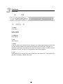
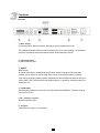
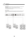
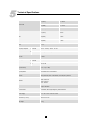
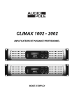
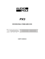
 PX3
PROFESSIONAL POWER AMPLIFIER
USER’S MANUAL
Important Safety Instructions
This symbol, wherever used, alerts you to the presence of un-insulated and dangerous voltages within
the product enclosure. These are voltages that may be sufficient to constitute the risk of electric shock or
death.
This symbol, wherever used, alerts you to important operating and maintenance instructions.
POWER SUPPLY
Ensure that the insource voltage (AC outlet) matches the voltage rating of the product. Failure to do so could result in
damage to the product and possibly the user. Unplug the product before electrical storms occur and when unused for
long periods of time to reduce the risk of electric shock or fire.
EXTERNAL CONNECTION
Always use proper ready-made insulated mains cabling (power cord). Failure to do so could result in shock/death or fire.
If in doubt, seek advice from a registered electrician.
DO NOT REMOVE ANY COVERS
Within the product are areas where high voltages may present. To reduce the risk of electric shock do not remove any
covers unless the AC mains power cord is removed. Covers should be removed by qualified service personnel only. No
user serviceable parts inside.
FUSE
To prevent fire and damage to the product, use only the recommended fuse type as indicated in this manual. Do not
short-circuit the fuse holder. Before replacing the fuse, make sure that the product is OFF and disconnected from the AC
outlet.
PROTECTIVE GROUND
Before turning the unit on, make sure that it is connected to Ground. This is to prevent the risk of electric shock.
Never cut internal or external Ground wires. Like wise, never remove Ground wiring from the Protective Ground
Terminal.
OPERATING SAFETY INSTRUCTIONS
Read these instructions. Follow all instructions. Keep these instructions. Do not discard. Heed all warnings. Only use
attachments/accessories specified by the manufacturer.
POWER CORD AND PLUG
Do not tamper with the power cord or plug. These are designed for your safety. Do not remove Ground connections! If
the plug does not fit your AC outlet seek advice from a qualified electrician. Protect the power cord and plug from any
physical stress to avoid risk of electric shock. Do not place heavy objects on the power cord. This could cause electric
shock or fire.
SERVICING
Refer all servicing to qualified service personnel only. Do not perform any servicing then those instructions contained
within this User’s Manual.
DISPOSAL
This symbol indicates that the disposal of this product is submitted to local regulations. Please contact
your local dealer.
2 Index
1.
Introduction …………………………………………………………………….…..
4
2.
Main Features ……………....……..………………………………………………
4
3.
Functions …………………………………………………………………………..
5
4.
Applications ………………………………………………...……………….……..
7
5.
Technical Specifications ….………………………………………………...……
8
6.
Warranty ……………………………………………………………………….……
9
3 3
1
Introduction
Thanks for the acquisition of the PX3 AUDIOPOLE. This three channel power amplifier has been
developed to drive two satellites and one subwoofer in fixed installations requiring limited space in the
bays.
The PX-3 has a high efficiency thanks to his Class-D technology and can deliver
2 x 150 W RMS / 4 Ohms and 1 x 220 W RMS / 4 Ohms. It also works securely with 2 Ohms loads.
2
Main Features
……………
•
Class-D,
•
2 x 180 W / 4 Ohms + 1 x 220 W / 4 Ohms,
•
Balanced inputs on Euroblock connectors,
•
Speaker outputs on Euroblock connectors,
•
1U rack,
•
4.5 kg
4 4
3
Functions
FRONT PANEL
1 – POWER
Power switch.
2, 3 & 4 – Volume
Volume controls.
5 – POWER ON
Power indicator.
6 – SIG
Signal indicator.
7 – PROT
Protection indicator. If the amplifier fails, the Led lights up, the output being automatically muted. Check
the cable connection between the amplifier and the speakers. Also check that the vent grille is not
obstructed. If the amplifier is installed into a bay, there is a risk that the cooling is not sufficient and the
temperature can raise to the upper limit level where the protect mode is triggered.
8 – CLIP
Clipping indicator. The Led lights up as soon as the distortion rate exceeds 0.5%. The input level is too
high and it is necessary to decrease the volume.
5 5
3
Functions
Back Panel
1 – Mains and fuse
Power supply socket. Make sure that the cable plug is correctly inserted in the socket.
The compartment located below the socket contains the fuse. In the event of change, it is imperative to
use a fuse with identical electrical characteristics under threat of damage to the unit.
2 – Input connectors
Euroblock balanced inputs
3 – MODE
Mode selector:
In case the input signal is already filtered and the three channel including the SUB are already
available, use the selector on position SUB. Every channel will be amplified without any filtering.
If the input signal (stereo) needs a separate amplification for the low frequencies, push the selector on
position CHA + CHB. The device filters and amplifies signal A + B to feed the Subwoofer with the low
frequencies only.
4 – X-OVER FREQ
Cut off frequency selectors for hi-pass (CH A, CH B) and low-pass (SUB) filters. The value can be set
from 50 Hz to 250 Hz.
5, 6 & 7 – Speakers connectors
Euroblock speakers output.
8 – Vent grille
Check that the vent grille is not obstructed. 6 6
4
Applications
Inputs connections
The inputs can be connected to the Euroblock socket using the female free part connectors supplied
with the device.
For balanced inputs use Hot pin (+), Cold pin (-) and Ground pin (G) terminals.
For unbalanced inputs use Hot pin (+) and Ground pin (G) only; Hot (+) and Cold (-) must be
connected together in the female connector.
Speaker connections
Check that the polarity is well respected for every speaker. Two Euroblocks connected point to point
are available for easy parallel set up. The impedance output must not be less than 2 Ohms per
channel.
7 7
5
Technical Specifications
CHA & CHB
SUB
TDH
Frequency Response
Input Sensitivity
Input Impedance
4 Ω (RMS)
8 Ω (RMS) 4 Ω (RMS) 8 Ω (RMS) SUB
20 Hz – (50Hz – 250 kHz) +0/-3 dB 28 ± 0,5 dB
SUB 30 ± 0,5 dB 2 x 150 W
2 x 90 W 400 W
220 W 120 W > 96 dB
CHA & CHB
2 x 250 W
< 0,1%
(50 Hz – 120 kHz) – 20 kHz +0/-1 dB
2 Ω (EIAJ)
CHA & CHB
S/N rate
Gain (V)
2 Ω (EIAJ)
0,9-1,1 V (0+/-1 dBv)
20 kΩ balanced or 10 kΩ unbalanced
Controls
Front panel: On/Off Power Switch, volume channel A, B & SUB
Rear panel: SUB, CHA + CHB selector; Cut off frequency selectors
Indicators
POWER ON : Blue Led
SIGN : Green Led
PROT : Red Led
CLIP : Red Led
Connectors
Inputs: Euroblock
Outputs: Euroblock
Load Protection
Power Supply
Dimensions (L x D x H)
Net Weight
On/Off Mute, DC fault grounding relay, internal fault fuses
110 - 120 V or 220 - 240 V 50 ~ 60 Hz
483 x 281 x 44 mm
4.5 kg
8 8
6
Warranty
This device is warranted parts and labor against any manufacturing defects for a period of two years
from the date of purchase by the first user.
Conditions
1. The unit has been installed and implemented by observing the safety instructions in this
operating manual.
2. The device was not diverted from its destination, either voluntary or accidental, and suffered no
deterioration or modification other than those described here or explicitly authorized by
AUDIOPOLE.
3. All modifications or repairs have been carried out by an authorized service station.
4. The defective product must be returned with the dealer who made the sale or to an authorized
service station with proof of purchase.
5. The device was properly packaged to avoid damage in transport.
22, rue Édouard Buffard, Z.A.C. de la Charbonnière, Montévrain - 77771 Marne-la-Vallée Cedex 4 - France
Tél : + 33 (0)1 60 54 32 00 - Fax : + 33 (0) 1 60 54 31 90 - www.audiopole-pa.com - www.audiopole.fr