1
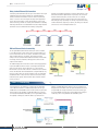
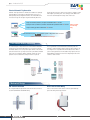
Industrial I/O
2AR
Groupe
ioLogik E1200 Series
Remote Ethernet I/O with 2-port Ethernet Switch
››Built-in 2-port Ethernet switch for daisy-chain topologies
››Free support of Moxa’s push-based Active OPC Server Lite
··Seamlessly connect to any SCADA system
··Save 80% on network bandwidth
··I/O response that’s seven times faster
››User-defined Modbus/TCP addressing
››MXIO programming library for Windows and WinCE VB/VC.NET
and Linux C APIs
››Web configuration with Import/Export function
Introduction
Star-topology for Ethernet Automation
Ethernet requires infrastructure equipment such as switches for
connecting a variety of different devices to the network. This is
unlike most field-bus automation networks that use a daisy-chain
topology, which presents a bit of a problem for Ethernet automation
applications since when connecting to Ethernet, meters and gauges
Rg2i
must be formed in a “star” configuration. The ioLogik E1200 series
provides an alternative to spending the time and money needed to
figure out the best way to hook up your Ethernet switches. Since each
E1200 unit has two built-in Ethernet switches, the E1200 solution is
tailor-made for a daisy-chain type configuration.
Interfaces pour l’informatique
Groupe 2AR
26, rue Bergson
42000 Saint Etienne - France
Tél.: +33 (0) 4 77 92 03 56
Fax: +33 (0) 4 77 92 03 57
www.rg2i.fr - [email protected]
1
Rémy GUÉDOT
Produits et Solutions en
Communication Industrielle
Acquisition de Données et
Transport de l’Information
w w w. m o x a . c o m
[email protected]
Industrial I/O
2AR
Groupe
Daisy-chained Ethernet I/O Connection
A new daisy-chained Ethernet I/O concept is now available. The ioLogik
E1200 industrial remote Ethernet I/O has two embedded Ethernet
switch ports that allow information to flow to another local Ethernet
device or connect to the next ioLogik in the daisy-chain. Applications
such as factory automation, security and surveillance systems, and
tunnel monitoring, can make use of daisy-chained Ethernet for building
multi-drop I/O networks over standard Ethernet cables. Many industrial
automation users are familiar with the multi-drop configuration
typically used in fieldbus applications. The daisy-chain function on the
remote Ethernet I/O ioLogik E1200 not only increases the connection
between machines and panels, but also lowers the cost of buying
separate Ethernet switches, and at the same time reduces labor fees
and cabling by a large percentage. For example, if a production facility
contains 700 stations (20 points per station), the wiring cost reduction
can reach 15% of the total implementation cost.
Efficient Ethernet Device Connectivity
The ioLogik E1200’s built-in Ethernet switch ports can be cascaded
to other Ethernet devices at the same location. A typical situation is a
remote site that has a few sensors, devices, and Internet connectivity.
Take a roadside cabinet as an example. The IP camera monitors
activity on the street and an Ethernet I/O device handles environmental
monitoring, intrusion, and alarms, and triggers the camera to take
snapshots when needed.
The traditional approach for this kind of remote monitoring application
requires an additional switch or hub for connecting the Ethernet I/O
device to the IP camera. A better approach is to connect another
Ethernet device such as a PLC controller or an IPC in the same cabinet
and use the industrial switch embedded in the ioLogik E1200. Not only
does this solution reduce the number of failure points associated with
an additional switch or hub, but it also reduces the amount of wiring
needed for power, signals, and the network. Space inside the cabinet
can also be saved.
Smart I/O Connectivity
Several approaches are available for controlling the ioLogik E1200
over an Ethernet network. As a traditional I/O solution, the ioLogik
E1200 allows a central SCADA system or field controller to poll the I/O
channel status via the standard, open Modbus/TCP protocol. Except
for the default fixed Modbus/TCP address, the ioLogik E1200 provides
the capability of letting users define the address by themselves. In
2
addition, the MXIO(.NET) library makes it easy for programmers to
integrate their own software to the ioLogik in the field. Moreover, the
ioLogik E1200 can leverage the benefits of the active technology of
the ioLogik E2000 series with the free Active OPC Server package to
seamlessly connect to any Windows-based SCADA system.
w w w. m o x a . c o m
[email protected]
Industrial I/O
2AR
Groupe
OPC Connection to SCADA
Free Push-based Active OPC Server Lite Package
Active OPC Server Lite is a free software package provided by Moxa
that operates as an OPC driver for an HMI or SCADA system. General
OPC servers typically use the “poll/response,” or so-called “pull”
architecture, to connect to Ethernet I/O devices, which involves an
HMI/SCADA system continuously sending out commands to collect
relevant data. Moxa’s Active OPC Server Lite, with its non-polling
architecture, supports the standard OPC protocol, but also offers active
(or “push”) communication with Moxa’s ioLogik series of Ethernet
I/O products to HMI/SCADA systems, providing instant I/O status
reports with “Active Tags.” The event-driven active tags result in an I/O
response time that is 7 times faster than other OPC Server packages,
and results in an apparent 80% reduction in network traffic.
Dynamic IP/WAN Connection
Active OPC Server Lite and ioLogik products provide the flexibility
of configuring the ioLogik E1200 to use dynamic IP addresses. The
ioLogik E1200 connects directly to the Active OPC Server Lite instead
of being polled, which makes dynamic IP addressing and WAN Access
to the Ethernet I/O device possible, and adds even greater flexibility by
allowing connections across firewalls. I/O devices for traditional data
acquisition applications are not capable of using this approach.
Pull-based OPC Server
General OPC Server
Polls continuously
Local Network and Fixed IP Connection only
Remote I/O
Remote I/O
Remote I/O
Push-based Active OPC Server
Active OPC Server
No polling required
3
Router
Internet and Dynamic IP
Connection
Router
w w w. m o x a . c o m
ioLogik
[email protected]
Industrial I/O
2AR
Groupe
Patented Automatic Tag Generation
Patented “Auto Tag Generation” eliminates the headache of specifying
target IP addresses, I/O channels, and data formats one by one, or
editing and importing configuration text files since Active OPC Server
Lite creates the tags for the target ioLogik automatically. One of the
biggest payoffs is that users will no longer need to be trained to install
and configure your OPC system, since setting up Active OPC Server
Lite is done automatically with a single click of the mouse.
5 steps for channels, interfaces, and protocol definition: takes 20 seconds.
13 steps for device, IP address, and other communication parameters: takes 30 seconds.
1 step for looking up address table: takes 100 seconds.
General OPC Server
Select channels and press
Active OPC Server
Create Tags
It takes 2.5 min.
to create only
1 tag
button to update configuration: takes 5 seconds.
It takes 5 seconds to create 20 or more tags
ioLogik
User-defined Modbus Addressing
To control an input or output channel of a remote Ethernet I/O device
running the most general Modbus/TCP protocol requires specifying
the Modbus address of those input and output channels. This can take
quite a bit of effort since you may need to look up the address and data
type in the user’s manual for address mapping, and can also cause
problems once the I/O channels change or a device is replaced.
The ioLogik E1200’s user-defined Modbus addressing offers the
flexibility to make the Modbus address dynamic, and the address can
be configured to be compatible with other Modbus devices. When a
system is being replicated, or the filed I/O is being replaced, the userdefined Modbus eliminates the effort of reconfiguring the PC control
software or field controller.
Mechanical Design
4
DIN and Wall Mountable
Stress-relief for Solid Wiring
The ioLogik E1200 is designed with a vertical form factor, and can be
used with both DIN-Rail and Wall Mounting.
A stress-relief connector at the bottom of the ioLogik E1200 helps
prevent the wiring from being pulled out.
w w w. m o x a . c o m
[email protected]
Industrial I/O
2AR
Groupe
Specifications
LAN
Relay Output
Ethernet: 2 x 10/100 Mbps switch ports, RJ45
Protection: 1.5 KV magnetic isolation
Protocols: Modbus/TCP, TCP/IP, UDP, DHCP, Bootp, HTTP
Type: Form A (N.O.) relay outputs, 5A
Contact Rating: 5 A @ 30 VDC, 5 A @ 250 VAC, 5 A @ 110 VAC
Inductance Load: 2 A
Resistance Load: 5 A
Breakdown Voltage: 500 VAC
Relay On/Off Time: 10 ms, 5 ms (Max.)
Initial Insulation Resistance: 1G min. @ 500 VDC
Expected Life: 100,000 times (Typical)
Initial Contact Resistance: 30 milli-ohms (Max.)
Pulse Output: 0.3 Hz at rated load
Analog Input
Type: Differential input
Resolution: 16 bits
I/O Mode: Voltage / Current
Input Range: 0 to 10 VDC, 4 to 20 mA
Accuracy:
±0.1% FSR @ 25°C
±0.3% FSR @ -10 and 60°C
Sampling Rate (all channels): 12 samples/sec
Input Impedance: 10M ohms (minimum)
Built-in Resistor for Current Input: 120 ohms
Power Requirements
Power Input: 24 VDC nominal, 12 to 36 VDC
Power Consumption: 130 mA typical @ 24 VDC
Physical Characteristics
Digital Input
Wiring: I/O cable max. 14AWG
Dimensions: 27.8 x 124 x 84 mm (1.09 x 4.88 x 3.31 in)
Weight:
ioLogik E1210: 171 g
ioLogik E1211: 187 g
ioLogik E1212: 171 g
ioLogik E1214: 177 g
ioLogik E1240: 179 g
Sensor Type: NPN, PNP, and Dry contact
I/O Mode: DI or Event Counter
Dry Contact:
• Logic 0: short to GND
• Logic 1: open
Wet Contact:
• Logic 0: 0 to 3 VDC
• Logic 1: 10 to 30 VDC (DI COM to DI)
Isolation: 3K VDC or 2K Vrms
Counter/Frequency: 150 Hz, power off storage
Environmental Limits
Operating Temperature: -10 to 60°C (14 to 140°F)
Storage Temperature: -40 to 85°C (-40 to 185°F)
Ambient Relative Humidity: 5 to 95% (non-condensing)
Digital Output
I/O Mode: DO or Pulse Output (up to 500 Hz)
Pulse Wave Width/Frequency: 1 ms/500 Hz
Over-voltage Protection: 45 VDC
Over-current Limit: 600 mA per channel
Over-temperature Shutdown: 175°C (typical), 150°C (min.)
Output Current Rating: Max. 200 mA per channel
Isolation: 3K VDC or 2K Vrms
Regulatory Approvals
EMI: FCC Part 15, CISPR (EN55022) class A
EMS: IEC 61000-4, IEC 61000-6
Shock: IEC 60068-2-27
Freefall: IEC 60068-2-32
Vibration: IEC 60068-2-6
Warranty
Warranty Period: 2 years
Details: See www.moxa.com/warranty
Dimensions (unit = mm)
27
27.8
124
132
Top View
84
Front View
5
Side View
Rear View
Down View
w w w. m o x a . c o m
[email protected]
Industrial I/O
2AR
Groupe
I/O Pin Assignment
ioLogik E1210
(top to bottom)
1
2
3
4
5
6
7
8
9
10
11
12
13
14
15
16
17
18
19
20
COM 0
DI0
DI1
DI2
DI3
GND
DI4
DI5
DI6
DI7
COM 1
DI8
DI9
DI10
DI11
GND
DI12
DI13
DI14
DI15
ioLogik E1212
(top to bottom)
ioLogik E1211
(top to bottom)
1
2
3
4
5
6
7
8
9
10
11
12
13
14
15
16
17
18
19
20
1
2
3
4
5
6
7
8
9
10
11
12
13
14
15
16
17
18
19
20
DO0
DO1
DO2
DO3
GND
DO4
DO5
DO6
DO7
DO8
DO9
DO10
DO11
GND
DO12
DO13
DO14
DO15
COM0
DI0
DI1
DI2
DI3
GND
DI4
DI5
DI6
DI7
COM1
DIO0
DIO1
DIO2
DIO3
GND
DIO4
DIO5
DIO6
DIO7
ioLogik E1214
(top to bottom)
1
2
3
4
5
6
7
8
9
10
11
12
13
14
15
16
17
18
19
20
COM
DI0
DI1
DI2
DI3
DI4
DI5
GND
R0_NO
R0_C
R1_NO
R1_C
R2_NO
R2_C
R3_NO
R3_C
R4_NO
R4_C
R5_NO
R5_C
ioLogik E1240
(top to bottom)
1
2
3
4
5
6
7
8
9
10
11
12
13
14
15
16
17
18
19
20
AI0+
AI0AI1+
AI1AI2+
AI2AI3+
AI3AI4+
AI4AI5+
AI5AI6+
AI6AI7+
AI7-
Ordering Information
ioLogik E1210: Remote Ethernet I/O with 2-port Ethernet switch and 16 DIs
ioLogik E1211: Remote Ethernet I/O with 2-port Ethernet switch and 16 DOs
ioLogik E1212: Remote Ethernet I/O with 2-port Ethernet switch, 8 DIs, and 8 DIOs
ioLogik E1214: Remote Ethernet I/O with 2-port Ethernet switch, 6 DIs, and 6 Relays
ioLogik E1240: Remote Ethernet I/O with 2-port Ethernet switch and 8 AIs
Rg2i
Groupe
2AR
Interfaces pour l’informatique
Rémy GUEDOT
Produits et Solutions en Communication Industrielle
Acquisition de Données et Transport de l’Information
26, rue Bergson - Le Millenium - 42000 Saint Etienne - France
Tél: +33 (0) 4 77 92 03 56 - Fax: +33 (0) 4 77 92 03 57
Internet: www.rg2i.fr
Email: [email protected]
6
© Moxa Inc. All Rights Reserved. Updated Aug. 27, 2009. Specifications subject to change without notice. Please visit our website for the most up-to-date product information.