1
Revised April 25, 2014
ACID, ACIDized, ACIDplanet.com, ACIDplanet, the ACIDplanet logo, ACID XMC, Artist Integrated, the
Artist Integrated logo, Beatmapper, Cinescore, CD Architect, DVD Architect, DoStudio, Jam Trax, Perfect
Clarity Audio, Photo Go, Sound Forge, Super Duper Music Looper, Transparent Technology, Vegas, Vision
Series, and Visual Creation Studio are the trademarks or registered trademarks of Sony Creative Software
Inc. in the United States and other countries.
PlayStation is a registered trademark and PSP is a trademark of Sony Corporation Entertainment Inc.
HDV and HDV logo are trademarks of Sony Corporation and Victor Company of Japan, Limited (JVC).
"ATRAC," "ATRAC3," "ATRAC3plus," "ATRAC Advanced Lossless," and the ATRAC logo are trademarks of
Sony Corporation. http://www.sony.net/Products/ATRAC3/
All other trademarks or registered trademarks are the property of their respective owners in the United States
and other countries. For more information, see http://www.sonycreativesoftware.com/licensenotices.
Sony Creative Software Inc. may have patents, patent applications, trademarks, copyrights, or other
intellectual property rights covering subject matter in this document. Except as expressly provided in any
written license agreement from Sony Creative Software Inc., the furnishing of this document does not give
you any license to these patents, trademarks, copyrights, or other intellectual property.
Music recognition technology and related data are provided by Gracenote®. Gracenote is the industry
standard in music recognition technology and related content delivery. For more information visit
www.gracenote.com.
Sony Creative Software Inc.
8215 Greenway Blvd.
Suite 400
Middleton, WI 53562
USA
The information contained in this manual is subject to change without notice and does not represent a
guarantee or commitment on behalf of Sony Creative Software Inc. in any way. All updates or additional
information relating to the contents of this manual will be posted on the Sony Creative Software Inc. Web
site, located at http://www.sonycreativesoftware.com. The software is provided to you under the terms of
the End User License Agreement and Software Privacy Policy, and must be used and/or copied in
accordance therewith. Copying or distributing the software except as expressly described in the End User
License Agreement is strictly prohibited. No part of this manual may be reproduced or transmitted in any
form or for any purpose without the express written consent of Sony Creative Software Inc.
Copyright © 2014. Sony Creative Software Inc.
Program Copyright © 2014 Sony Creative Software Inc. All rights reserved.
Table of Contents
Table of Contents
Introduction
3
13
Technical Support
14
About Vegas Pro
14
Interactive Tutorials
14
The Vegas Pro Window
15
Main toolbar
16
Editing Tool
17
Time Display
20
Track List
21
Scrubbing
21
Timeline
23
Marker Bar
24
The Transport and Timeline Toolbar
25
Viewing the status bar
27
Window Docking Area and Floating Window Docks
29
The Explorer Window
30
The Trimmer Window
32
The Master Bus Window
33
The Video Preview Window
33
The Project Media Window
34
The Edit Details Window
34
The Transitions Window
35
The Video FX Window
36
The Media Generators Window
37
The Compositors Window
38
The Plug-In Manager Window
38
The Video Scopes Window
39
The Surround Panner Window
40
TABLE OF CONTENTS 3
The Media Manager Window
40
The XDCAM Explorer Window
41
The Mixing Console Window
42
The Device Explorer Window
42
Loudness meters
43
Working with projects
47
Creating a new project
47
Setting project properties
47
Opening a project or media file
56
Creating rotated projects
59
Nesting projects
61
Opening a recent project
63
Saving a project
63
Automatic project saving
63
Saving and renaming a project (Save As)
63
Project references in rendered files
65
Sharing a project online
66
Uploading your movie to YouTube
66
Importing and exporting projects
68
Importing and exporting AAF files
70
Archiving projects
73
Working with P2 Video
73
Exporting a movie to a PSP™
74
Edit Decision Lists
76
Closing a Project
77
Exiting the Vegas Pro Application
77
Adding, managing, and arranging media
79
Using the Project Media window
79
Previewing media files
86
Adding media files to your project
87
Adding layered PSD files to the timeline
92
Creating a picture slideshow
93
4 TABLE OF CONTENTS Importing media from a project file
94
Importing Broadcast Wave Format files
95
Importing video from a DVD camcorder
97
Editing video from an XDCAM Station with StreamChase
98
Using the Device Explorer
100
Creating proxy files for high-definition editing
102
Using HitFilm effects
103
Sorting your media with bins
103
Viewing or changing media file properties
105
Recording audio
111
Metronome
116
Capturing video
117
Capturing from an SDI card
118
Capture preferences
121
Capturing HDV clips
125
Converting video to 24p
126
Extracting audio from CDs
127
Obtaining CD information
128
Getting media from the Web
129
Editing events on the timeline
131
Inserting an empty event
131
Inserting time
131
Creating selections and positioning the cursor
132
Moving events
135
Automatic crossfades
136
Enable snapping
137
Quantize to frames
140
Cutting, copying, and pasting events
140
Deleting events
144
Trimming events
145
Post-edit ripple
146
Splitting events
148
TABLE OF CONTENTS 5
Shuffling events
149
Using the Trimmer
150
Adjusting an event's length
158
Expanded edit mode
161
Slipping and sliding events
163
Repairing audio/video synchronization offsets
165
Event envelopes
166
Stabilizing video clips
170
Reversing an event
171
Using takes as alternate versions of events
171
Grouping events
173
Using sync links
174
Applying switches to events
175
Audio streams
177
Audio channels
177
Opening events in an audio editor
178
Opening a copy of an event in an audio editor
179
Editing event properties
180
Copying and pasting event attributes
185
Using the Edit Details Window
185
Removing red eye from still images
186
Undoing and redoing edit operations
187
Rebuild audio peaks
188
Zooming and magnification
188
Multicamera editing
191
Shooting multicamera video
191
Capturing multicamera video
192
Synchronizing video in multicamera projects
192
Creating multicamera events
193
Editing multicamera video
194
Stereoscopic 3D editing
Setting up your stereoscopic 3D project
6 TABLE OF CONTENTS 201
201
Setting up stereoscopic 3D previews
206
Synchronizing stereoscopic 3D events
206
Aligning left- and right-eye views and adjusting depth
210
Rendering a stereoscopic 3D project
212
Using markers, regions, and commands
217
Inserting markers
217
Inserting regions
218
Using media markers and regions
220
Inserting command markers
221
Inserting CD track regions
224
Inserting CD index markers
225
The Marker Tool
226
Track editing
227
Inserting audio tracks
227
Inserting video tracks
227
Selecting tracks
228
Arranging tracks
229
Grouping tracks
229
Duplicating tracks
231
Audio track controls
231
Video track controls
240
Audio bus tracks
246
Video bus track
248
Setting default track properties
252
Render to New Track
253
Using automation
255
Audio track automation
255
Video track automation
260
Automating audio effect parameters
263
Adjusting envelopes
266
Recording track envelope and keyframe automation
270
Animating video events and tracks
275
TABLE OF CONTENTS 7
Panning and cropping video events
275
Editing track motion
286
Keyframe animation
293
Applying effects
299
Adding audio track effects
299
Adding audio event effects
301
Using bus effects
302
Applying non-real-time event effects
304
Using assignable effects
304
Adding an assignable effects chain
305
Routing tracks to an assignable effects chain
306
Using assignable effects envelopes
307
Removing an assignable effects chain
308
Creating and using effects packages
308
Bypassing all audio effects
308
Editing audio effects
309
Adding video effects
313
Adding transitions
317
Adding generated media to your project
322
Using the Titles & Text Plug-In
323
Creating text and titles
326
Mixing audio
329
Using the Master Bus Window
329
Busses - overview
331
Adding audio busses
332
Assigning tracks to busses
333
Using bus envelopes
334
Routing busses
334
Signal flow diagram
336
Using input busses
337
Adding or deleting input busses
337
Recording using an input bus
339
8 TABLE OF CONTENTS Using input busses with hardware-based effects
341
Real-time rendering
343
The Mixing Console
345
The Mixing Console Toolbar
346
The Channel List Pane
348
The View Controls Pane
349
Channel Strips
350
Using the Mixing Console
352
Adding Track, Assignable FX, and Bus Channels
352
Audio Track Channel Strips
353
Bus Channel Strips
361
Input bus channel strips
367
FX send (assignable effects) channel strips
373
Creating a cue (headphone) mix with the Mixing Console
380
Compositing video
383
Compositing and masks
383
3D compositing
389
Video signal flow diagram
398
Proxy-first workflow
401
Working with HDV
403
Capturing HDV clips
403
Editing HDV video on the timeline
404
Working with XDCAM video
405
XDCAM EX workflow
405
XDCAM and XDCAM HD workflow
406
Setting up an XDCAM Device
406
Using the XDCAM Explorer Window
407
Importing XDCAM Discs
410
Editing XDCAM Clips on the Timeline
412
Exporting Video to XDCAM Discs
413
Working with RED camera clips
417
Working with AVCHD video
419
TABLE OF CONTENTS 9
S-Log and ACES workflow in Vegas Pro 13.0
421
Enabling color management in your Vegas Pro project
428
Specifying the color space for individual shots
430
Specifying the color space in a custom rendering template
430
5.1 surround projects
433
Setting up your 5.1 surround project
433
5.1 surround panning and mixing
436
Audio panning modes
444
Rendering your 5.1 surround project
447
Exporting a Vegas Pro project to DVD Architect Pro
449
Closed Captioning
451
Adding closed captioning to video files
451
Captioning Windows Media files
462
Previewing your project
465
The Transport and Timeline Toolbar
465
Loop Playback
467
Mute All Audio
468
Mute All Video
468
Using the Video Preview window
468
Split-screen previews
475
Using dynamic RAM previews
476
Using an External Video Monitor
477
External monitor via DVI (Windows Graphics Card)
478
External monitor via IEEE-1394 (FireWire)
479
External monitor via SDI
480
Selectively prerender video
481
Cleaning up prerendered video files
482
Loudness metering and logging
483
Loudness meters
483
Generating a loudness log
486
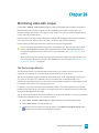
Monitoring video with scopes
489
The Vectorscope Monitor
489
10 TABLE OF CONTENTS The Video Waveform Monitor
490
The Histogram Monitor
491
The RGB Parade Monitor
494
Video Scope Settings
495
Timecode synchronization
497
Generate MIDI Timecode
497
Generate MIDI Clock
498
Trigger from MIDI Timecode
498
Burning discs
501
Track-at-once (TAO) CD burning
501
Disc-at-once (DAO or Red Book) CD Burning
502
Burning a Blu-ray Disc from the timeline
508
Burning a DVD from the timeline
510
Printing video to tape
511
Printing video to tape from the timeline
511
Printing video to HDV tape
519
Rendering projects (Render As)
523
Rendering Multichannel Audio Files
528
Rendering MPEG Files
531
Rendering Projects for Use in DVD Architect Pro
531
Media File Settings for Blu-ray Disc Projects
533
Custom rendering templates
536
Using Vegas Pro Connect
539
Setting up Vegas Pro Connect
539
Using Vegas Pro Connect to control playback
541
Using Vegas Pro Connect to review projects on your mobile device
546
Adjusting Vegas Pro Connect settings
550
Troubleshooting Vegas Pro Connect Connections
551
Using hardware controllers
553
Using a control surface
553
Using a Mackie Control
555
Using a Frontier TranzPort
570
TABLE OF CONTENTS 11
Using a PreSonus FaderPort
572
Using a Generic Control Surface
574
Configuring a Generic Control Surface
576
Using a joystick for panning, adjusting controls, and color correction
578
Using a multimedia controller
581
Using Scripting
585
Customizing the Vegas Pro interface
591
Customizing the toolbar
591
Customizing keyboard shortcuts
591
Customizing ASIO port naming
593
Time ruler
595
Grid spacing
598
Saving and recalling window layouts
598
Vegas Pro preferences
601
Preferences - General Tab
601
Preferences - Video Tab
607
Preferences - Preview Device Tab
610
Preferences - Audio Tab
618
Preferences - Audio Device Tab
622
Advanced Audio Configuration
624
Preferences - MIDI Device Tab
625
Preferences - VST Effects
626
Preferences - Editing Tab
626
Preferences - Display Tab
630
Preferences - CD Settings Tab
632
Preferences - Sync Tab
633
Preferences - External Control & Automation Tab
635
Keyboard shortcuts
639
Glossary
655
Index
675
12 TABLE OF CONTENTS Chapter 1
Introduction
Sony Creative Software Inc. proudly introduces Vegas® Pro, a full-featured nonlinear editor (NLE) for video
and multitrack digital audio designed for video postproduction and multichannel audio recording and
mixing.
What's new in version 13.0
Video
n Added support for rendering Video for Windows (.avi), QuickTime (.mov), and Windows Media
Video (.wmv) with frame sizes up to 4096x4096.
n Added a QFHD 24p template to the Project Properties dialog to allow you to create projects with a
frame size of 3840x2160 and a frame rate of 23.976 fps.
Audio
n Added loudness meters and logging.
Workflow
n Improved project archiving.
n Added a proxy-first workflow for efficient mobile editing when using CBK-WA100/CBK-WA101
wireless adapters: upload video proxies to the cloud or other server, start editing your project using
proxy media, and relink to full-resolution media when you're ready to finalize your project.
n Streamlined the main toolbar and added timeline-editing controls to the Transport and Timeline
toolbar below the timeline.
n Added Vegas Pro Connect.
When you're working with Vegas Pro, you can use Vegas Pro Connect to remotely control the Vegas
transport functions, seek and scrub the timeline, and add markers.
When you're on the go, you can use Vegas Pro Connect to bring your projects with you for review on
your mobile device.
n A new Allow floating windows to dock setting on the Preferences > Display tab allows you to
choose whether windows float or dock when moving them.
n A new Automatically create video proxies for Ultra HD media setting on the Preferences > Video
tab allows you to choose whether automatically create video proxy files when adding 4K video to
your project.
INTRODUCTION 13
Formats
n Added support for reading metadata (including timecode) in XAVC S files.
n Added support for no-recompress rendering (smart rendering) of XAVC Intra MXF video.
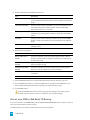
Technical Support
If you experience problems or have questions while using Vegas Pro, our technical support department is
always ready to help you. Additional support and information can be found at
http://www.sonycreativesoftware.com.
n For a detailed list of Technical Support options, please visit
http://www.sonycreativesoftware.com/support/default.asp.
n To listen to your support options, please call 608-256-5555.
About Vegas Pro
From the Help menu, choose About Vegas Pro to display information about the application, such as the
software license owner, copyright and system information, program version and serial number, and the
Vegas Pro logo.
Before contacting Technical Support, click the Computer tab to display information about your
computer.
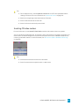
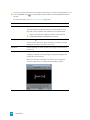
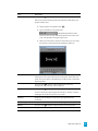
Interactive Tutorials
From the Help menu, choose Interactive Tutorials to start an interactive guide that will show you each part
of the Vegas Pro interface and teach you how to create projects.
Choose a topic from the Interactive Tutorials overview to start a tutorial—you'll be up and running in no
time!
14 CHAPTER 1
Chapter 2
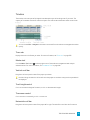
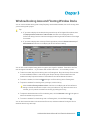
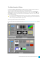
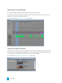
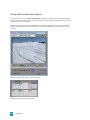
The Vegas Pro Window
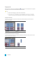
The Vegas® Pro window is where you edit your project, and the screen is divided into several areas.
Tips:
n If you prefer to work with the timeline at the bottom of the window and the docking area at
the top of the window, select the Display timeline at bottom of main window check box on
the Display tab of the Preferences dialog. For more information, see "Preferences - Display
Tab" on page 630.
n The track list, timeline, and window docking area sections can be sized to your preferences by
dragging the dividers between them or by using F11:
o F11 minimizes and restores the window docking area.
o Shift+F11 minimizes and restores the track list.
o Ctrl+F11 maximizes and restores the timeline vertically and horizontally (window
docking area and track list will be hidden).
THE VEGAS PRO WINDOW 15
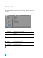
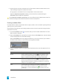
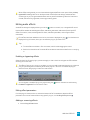
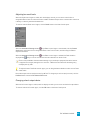
Main toolbar
From the View menu, choose Toolbar to toggle the display of the main toolbar.
The toolbar contains buttons that enable you to select frequently used commands quickly. You can
customize it by adding, removing, or reordering buttons. For more information, see "Customizing the
toolbar" on page 591.
Button Name
Description
New Empty
Project
Creates a new blank project using the default settings. For more
information, see "Creating a new project" on page 47.
Open
Opens an existing project or media file. For more information, see
"Opening a project or media file" on page 56.
Save
Saves the current project. For more information, see "Saving a
project" on page 63.
Save As
Saves the current project to a new name or folder. When you use
Save As, you can choose to copy the project media to the same folder
as your project. For more information, see "Saving and renaming a
project (Save As)" on page 63.
Render As
Saves your project in a new format as a single file. For more
information, see "Rendering projects (Render As)" on page 523.
Properties
Opens the Project Properties dialog box allowing you to make
changes to the current project. For more information, see "Setting
project properties" on page 47.
Cut
Deletes and copies the current event selection to the clipboard. For
more information, see "Cutting, copying, and pasting events" on
page 140.
Copy
Copies the current event selection to the clipboard. For more
information, see "Cutting, copying, and pasting events" on page 140.
Paste
Pastes the contents of the clipboard at the current cursor position. For
more information, see "Cutting, copying, and pasting events" on
page 140.
Undo
Reverses the last action performed. For more information, see
"Undoing and redoing edit operations" on page 187.
Redo
Reverses the action of the Undo command. For more information,
see "Undoing and redoing edit operations" on page 187.
Interactive
Tutorials
Starts an interactive guide that will show you each part of the Vegas
Pro interface and teach you how to create projects. For more
information, see "Interactive Tutorials" on page 14.
What's This
Help
Displays context-sensitive help.
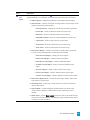
16 CHAPTER 2
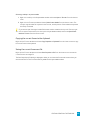
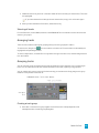
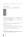
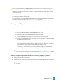
Editing Tool
Choose Edit > Editing Tool and select a tool from the submenu to change the active tool.
Normal
Choose Edit > Editing Tool and select a tool from the submenu.
This tool gives you the most flexibility while editing; selection, project navigation, most envelope editing,
etc. The only functions you cannot perform while in normal editing mode are box selection, box
magnification, and multiple envelope point selection.For more information, see "Adjusting envelopes" on
page 266.
Click the down arrow next to the Normal tool and choose a tool from the menu to select the mode that
will be used for editing events. For more information, see "The Transport and Timeline Toolbar" on page
465.
Tool
Normal Edit Tool
Description
Use to select, move, and trim the ends of events.
Click an event to select it. Hold Ctrl while clicking to select multiple
events, or hold Shift to select all events between the first and last
event you click.
Select events and drag them along the timeline to move them.
Drag either edge of an event to change its length. The event edge will
snap to grid lines if snapping is on. Hold the Shift key while dragging
to temporarily suspend snapping.For more information, see "Enable
snapping" on page 137.
For more information, see "Creating selections and positioning the
cursor" on page 132,"Moving events" on page 135, or "Adjusting an
event's length" on page 158.
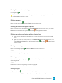
Shuffle Tool
Use to rearrange events on the timeline. For more information, see
"Shuffling events" on page 149.
Right-click and drag an event to a new location on the timeline
and choose Shuffle Events from the shortcut menu to shuffle
events when the Shuffle Tool is not active.
Slip Tool
Use to slip an event's media without moving the event on the
timeline. For more information, see "Slipping and sliding events" on
page 163.
Hold Alt while dragging an event to slip events when the Slip
Tool is not active.
THE VEGAS PRO WINDOW 17
Tool
Slide Tool
Description
Use to move an event on the timeline without moving the underlying
media. For more information, see "Slipping and sliding events" on
page 163.
Hold Ctrl+Alt while dragging an event to slide events when the
Slide Tool is not active.
Time
Stretch/Compress Tool
Use to make events longer or shorter while changing the velocity of
the media to create fast- or slow-motion effects. For more
information, see "Adjusting an event's length" on page 158.
Hold Ctrl while dragging the edge of an event to time
stretch/compress events when the Time Stretch/Compress Tool
is not active.
Split Trim Tool
Use to split an event at the point you click and trim the event in the
direction you drag (eraser mode). For more information, see "Slipping
and sliding events" on page 163.
Hold Ctrl+Alt+ Shift and drag to split trim events when the Split
Trim Tool is not active.
Envelope
To use the Envelope tool
, choose Edit > Editing Tool > Envelope.
The Envelope tool is designed to manipulate envelopes in events. With the Envelope tool selected, you can
add, delete, select, and move envelope points, but events cannot be moved or edited.For more information,
see "Adjusting envelopes" on page 266.
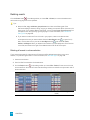
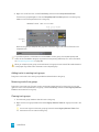
Selection
To use the Selection tool
, choose Edit > Editing Tool > Selection.
The Selection tool is designed to select multiple events across tracks by drawing selection boxes around the
events you want to include. The Selection tool can draw three types of selection boxes:
Type
Description
Free Selection
The default behavior of the tool:
n Click to select individual events (hold Shift or Ctrl to select
multiple events).
n Drag to draw a rectangular region that begins where you start
drawing and ends where you release the mouse button. All of
the events that are inside the region will be selected. This
method is good for selecting a group of events that are close
together.
18 CHAPTER 2
Type
Description
Vertical
Can be used to easily select all events that occur within a time range.
The vertical selection box automatically selects all of the tracks
between your first mouse click and where you draw the selection box;
even tracks that are not visible at the current magnification are
selected.
Horizontal
Can be used to easily select all events on a single or multiple adjacent
tracks. The horizontal selection box automatically selects all events
on a track that is touched by the selection box; even events that are
not visible at the current magnification are selected.
To change the type of selection box you are using, right-click the mouse while holding down the left mouse
button. Clicking the right mouse button will toggle through the three types of selection boxes.
Zoom
To use the Zoom tool , choose Edit > Editing Tool > Zoom. You can use the zoom tool to change the
magnification of the Vegas Pro project.
Click the Zoom button in the corner of the timeline to temporarily change the cursor into the Zoom
tool. Select an area of the timeline that you want to magnify, and the cursor will revert to the
previously active tool.
Before zooming, you can maximize the timeline by using the following shortcuts:
n Press F11 to maximize the timeline vertically (Window Docking area will be hidden).
n Press Ctrl+F11 to maximize the timeline vertically and horizontally (Window Docking area and Track
List will be hidden).
n Press Shift+F11 to maximize the timeline horizontally (Track List will be hidden).
Drag the mouse over the area you want to magnify. A dotted rectangle is drawn around the area, and the
area is magnified when the mouse button is released.
While holding the left mouse button, click the right mouse button to toggle through the three
magnification modes:
Item
Description
Free Zoom
The default behavior of the Zoom tool. Use this mode to zoom into a
section of your Vegas Pro project horizontally and vertically at the
same time.
Time Zoom
Use this mode to zoom horizontally without changing the vertical
magnification.
Track Height Zoom
Use this mode to zoom vertically without changing the horizontal
magnification.
THE VEGAS PRO WINDOW 19
Clicking anywhere in the project with the Zoom tool will zoom out so that the entire project fits in the
timeline, and as many tracks as possible will be displayed.
Next Tool
Choose Next Tool (or press D) to switch to the next tool in the list. For example, if you're using the Normal
tool, Next Tool selects the Envelope tool.
Previous Tool
Choose Previous Tool (or press Shift+D) to switch to the next tool in the list. For example, if you're using the
Envelope tool, Previous Tool selects the Normal tool.
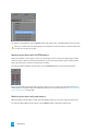
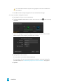
Time Display
The Time Display window shows the current cursor position, MTC input, MTC output, or MIDI clock output
time.
Right-click the window and choose a command from the submenu to change the display format.
Item
Description
Time at Cursor
Displays the current cursor position using the current time format.
MIDI Timecode In
Displays incoming MIDI timecode. For more information, see
"Trigger from MIDI Timecode" on page 498.
MIDI Timecode Out
Displays outgoing MIDI timecode. For more information, see
"Generate MIDI Timecode" on page 497.
MIDI Clock Out
Displays outgoing MIDI clock. For more information, see "Generate
MIDI Clock" on page 498.
Time Format
Choose Time Format and choose a setting from the submenu to set
the time units used in the Time Display and Time Ruler. For more
information, see "Time ruler" on page 595.
Text Color
Choose Custom to specify the color that will be used to display the
text in the window.
Background Color
Choose Custom to specify the color that will be used to display the
background of the window.
Changing the Time Display window colors affects only the
current color scheme. You can change the color scheme on the
Display tab of the Preferences dialog.
20 CHAPTER 2
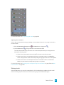
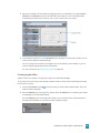
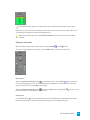
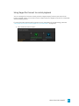
Track List
The track list displays all of the audio and video tracks in your project and contains the master controls for
each track. A scrub control and playback rate slider is also available below the track list.
For more information, see "Audio track controls" on page 231, "Video track controls" on page 240, and
"Scrubbing" on page 21,
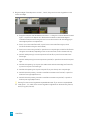
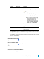
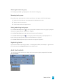
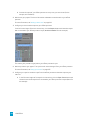
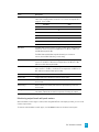
Scrubbing
You can use scrubbing to scroll playback of your project at varying speeds.
Choose a setting from the JKL / shuttle speed drop-down list on the Editing tab of the Preferences dialog to
control the scrub speed and range when you scrub with the JKL keys or with a multimedia controller. For
more information, see "Using a multimedia controller" on page 581.
Scrubbing with the playhead
Drag the playhead
edit point.
above the timeline to shuttle forward or backward from the cursor position to find an
Tips:
n Hold Alt, click the ruler, and drag to move the cursor to the position you clicked and scrub in
the direction you drag.
n Hold Ctrl while dragging (or drag while holding the right mouse button) to find audio when
you're zoomed out. The cursor moves in larger steps than with a regular drag.
n Hold Ctrl+Alt while dragging to scrub video only.
n Zoom in or out to adjust the scrub sensitivity. For more information, see "Zooming and
magnification" on page 188.
THE VEGAS PRO WINDOW 21
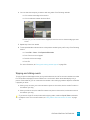
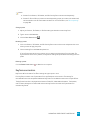
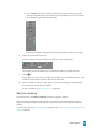
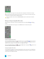
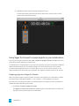
Using the scrub control in the track list
Drag the scrub control to shuttle forward or backward from the cursor position to find an edit point.
You can drag the Normal Rate indicator below the scrub control (or double-click the label to type a
playback rate) to adjust playback speed when you click the Play
or Play from Start
button.
Scrubbing with the cursor
1. Hover over the cursor in an area of the timeline that does not contain an event and press Ctrl. The
mouse pointer is displayed as a
.
When the Allow Ctrl+drag cursor style scrub over events check box on the General tab of the
Preferences dialog is selected, you can scrub with the mouse even when the cursor is over an
event.
2. Drag left or right to scrub playback.
Scrubbing with the keyboard
Press the J, K, or L keys to use the keyboard as a scrub control.
Press and hold K while pressing J or L to emulate a shuttle knob mode. Press K+J to turn the knob to
the left or K+L to turn the knob to the right.
Item
Description
J
Scrub reverse mode. Press again to accelerate the
playback rate.
K
Pause.
L
Scrub forward mode. Press again to accelerate the
playback rate.
22 CHAPTER 2
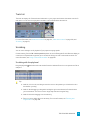
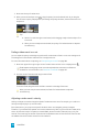
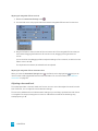
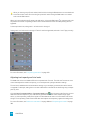
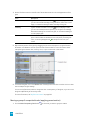
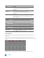
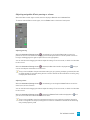
Timeline
The timeline is the main part of the Vegas Pro window where you will be doing most of your work. The
majority of the window consists of actual track space. This area contains the drawn events on each track.
You can choose Edit > Navigate and choose a command from the submenu to navigate the timeline
quickly.
Time ruler
Displays the time in the format you select. For more information, see "Time ruler" on page 595.
Marker tool
Click the Marker Tool button
in the top-right corner of the timeline to navigate and edit multiple
selected markers. For more information, see "The Marker Tool" on page 226.
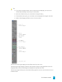
Vertical scroll bar
Drag the scroll box to pan the view of the project up or down.
Double-clicking the vertical scroll bar will zoom the project out so that as many tracks as possible will
be displayed.
Track height control
Click + to increase the height of the tracks, or click - to decrease track height.
Time zoom control
Click + to zoom in horizontally, or click - to zoom out.
Horizontal scroll bar
Drag the scroll box to pan the view of the project left or right. The ends of the scroll bar also function as
THE VEGAS PRO WINDOW 23
zoom controls. You can zoom the project in and out by dragging the edges of the scroll box.
Double-clicking the horizontal scroll bar will zoom the project out so that the entire length of the
project will be displayed.
Zoom tool
Click the Zoom Tool button
in the corner of the timeline to temporarily change the cursor into the Zoom
tool. Select an area of the timeline that you want to magnify, and the cursor will revert to the previously
active tool.
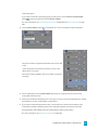
Marker Bar
The marker bar displays markers that you add to your project. Markers are a handy way to ease navigation
in the timeline. They can be used to indicate sections of projects, or you can use markers as snap points for
editing.
For information about inserting markers, see "Inserting markers" on page 217.
A shortcut menu is displayed when you right-click the marker bar:
Item
Description
Loop Playback
Sets the time selection range to repeat the music when played.
Set Selection to View
Sets the loop region to the visible edges of the timeline. If the entire
project is displayed, the loop region is set to the ends of the project.
Set Selection to Project
Sets the loop region to the ends of the project.
Select Loop Region
Creates a time selection based on the current loop region.
Markers/Regions
Choose a command from the submenu to add or delete markers or
regions. For more information, see "Inserting markers" on page 217
and "Inserting regions" on page 218.
Quantize to Frames
Forces edits to occur on frame boundaries. For more information, see
"Quantize to frames" on page 140.
Enable Snapping
When snapping is enabled, the Snap to Grid and Snap to Markers
commands become available. For more information, see "Enable
snapping" on page 137.
Snap to Grid
Select this command to force elements in the timeline to snap to the
grid. The grid is defined in units of time. For more information, see
"Enable snapping" on page 137.
Snap to Markers
Select this command to force elements in the timeline to snap to
markers. For more information, see "Enable snapping" on page 137.
24 CHAPTER 2
Item
Description
Snap to All Events
Select this command to force elements in the timeline to snap to the
ends of events on other tracks. For more information, see "Enable
snapping" on page 137.
Grid Spacing
Choose a command from the submenu to set the spacing of vertical
grid lines along the timeline.
Selectively Prerender
Video
Opens the Prerender Video dialog, where you can create a full-quality
preview of your project as it will appear in its final form. For more
information, see "Selectively prerender video" on page 481.
Clean Up Prerendered
Video
Removes the temporary files created as a result of using the
Selectively Prerender Video command. For more information, see
"Cleaning up prerendered video files" on page 482.
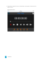
The Transport and Timeline Toolbar
The Transport and Timeline toolbar provides controls for playback, recording, and cursor-positioning
buttons and timeline editing.
During project playback, audio tracks will be mixed to the Master bus unless you are using a custom bus
assignment. Video tracks will be mixed to the Video Preview window.
For more information, see "Assigning tracks to busses" on page 333 and "Using the Video Preview window"
on page 468.
You can choose Edit > Navigate and choose a command from the submenu to navigate the timeline
quickly.
Button Name
Description
Record
Starts recording on all armed tracks. If no tracks are armed, a new
track will be created automatically. For more information, see
"Recording audio" on page 111.
Loop Playback
Plays only the events in the loop region in a continuous mode.
Play from Start Starts playback from the beginning of the project regardless of the
current cursor position. When you stop playback, the cursor returns to
its original position.
Play
Starts playback from the cursor position.
Select the Make spacebar and F12 Play/Pause instead of
Play/Stop check box in the General Preferences tab if you want
the F12 and spacebar keyboard shortcuts to toggle between
Play and Pause mode. In this mode, the cursor will maintain its
position.
Pause
Pauses playback and leaves the cursor at its current position.
Stop
Stops playback or recording and returns the cursor to its starting
position.
THE VEGAS PRO WINDOW 25
Button Name
Description
Go to Start
Moves the cursor to the beginning of the project.
Go to End
Moves the cursor to the end of the project.
Previous
Frame
Moves the cursor to the previous frame.
Next Frame
Moves the cursor to the next frame.
Normal Edit
Tool
Select this button to perform event editing. Click the down arrow
and choose a tool from the menu to select the mode that will be used
for editing events. For more information, see "Editing Tool" on page
17.
Click and hold the Previous Frame and Next Frame buttons to
move the cursor multiple frames.
n
Normal Edit Tool: Use to trim the ends of events. For more
information, see "Adjusting an event's length" on page 158.
n
Shuffle Tool: Use to rearrange events on the timeline. For
more information, see "Shuffling events" on page 149.
n
Slip Tool: Use to slip an event's media without moving the
event on the timeline. For more information, see "Slipping and
sliding events" on page 163.
n
Slide Tool: Use to move an event on the timeline without
moving the underlying media. For more information, see
"Slipping and sliding events" on page 163.
n
Time Stretch/Compress Tool: Use to make events longer
or shorter while changing the velocity of the media to create
fast- or slow-motion effects. For more information, see
"Adjusting an event's length" on page 158.
n
Split Trim Tool: Use to split an event at the point you click
and trim the event in the direction you drag (eraser mode). For
more information, see "Slipping and sliding events" on page
163.
Envelope Edit
Tool
Select this button when you want to edit multiple envelopes without
moving the events. For more information, see "Editing Tool" on page
17.
Selection Edit
Tool
Select this button when you want to select multiple events. For more
information, see "Editing Tool" on page 17.
Zoom Edit Tool Magnifies the current project. For more information, see "Editing
Tool" on page 17.
Delete
26 CHAPTER 2
Deletes the selected events or tracks. For more information, see
"Deleting events" on page 144.
Button Name
Description
Trim
Trims a time selection. For more information, see "Trimming events"
on page 145.
Trim Start
Trims the start of the selected event to the cursor. For more
information, see "Trimming events" on page 145.
Trim End
Trims the end of the selected event to the cursor. For more
information, see "Trimming events" on page 145.
Split
Click to split an event. For more information, see "Splitting events" on
page 148.
Lock
Locks an event so that it cannot be moved or edited. For more
information, see "Applying switches to events" on page 175.
Insert Marker
Adds a marker at the cursor position. For more information, see
"Inserting markers" on page 217.
Insert Region
Adds region tags at each end of the selection. For more information,
see "Inserting regions" on page 218.
Enable
Snapping
Turns on snapping and enables the Snap to Grid and Snap to
Markers commands. For more information, see "Enable snapping" on
page 137.
Automatic
Crossfades
Select this button to automatically create a crossfade when two or
more events overlap. For more information, see "Automatic
crossfades" on page 136.
Auto Ripple
Select this button and choose a mode from the drop-down list to
automatically ripple the contents of the timeline following an edit
after adjusting an event's length, cutting, copying, pasting, or
deleting events. For more information, see "Post-edit ripple" on page
146.
Lock Envelopes Select this button if you want envelope points to follow an event
to Events
when it is moved along the timeline. For more information, see
"Video track automation" on page 260.
Ignore Event
Grouping
Select this button to override event groups without removing the
groups. For more information, see "Grouping events" on page 173.
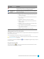
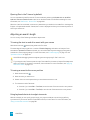
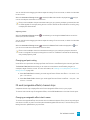
Viewing the status bar
From the View menu, choose Status Bar to toggle the display of the status bar at the bottom of the Vegas
Pro window.
The status bar displays help text when your mouse is over menu items, shows the available record time in
the selected folder, and will also show progress meters for any actions that take time to complete.
To change the recorded files folder, choose Properties from the File menu and click the Audio tab.For
more information, see "Setting project properties" on page 47.
THE VEGAS PRO WINDOW 27
28 CHAPTER 2
Chapter 3
Window Docking Area and Floating Window Docks
You can use the window docking area to keep frequently used windows available, but out of the way, while
you are working with a project.
Tips:
n If you want to display the window docking area at the top of the Vegas® Pro window, select
the Display timeline at bottom of main window check box on the Display tab of the
Preferences dialog. Clear the check box to display the docking area at the bottom of the Vegas
Pro window.
n If you want to display tabs at the top of docking windows, select the Position tabs at top of
docked windows check box on the Display tab of the Preferences dialog.
You can also create multiple floating docks to organize your Vegas Pro windows. These docks can float
over the Vegas Pro window or — if you have a dual-monitor video card — on a secondary monitor.
n To dock a window, drag it to the docking area or a floating dock. Drop near the top of the window
to create a tabbed window or a new docking area. Drop at the top of the window to dock the
window at the top. Drop at the bottom of the window to dock the window at the bottom.
n To undock a window, click the handle and drag it out of the docking area or floating dock.
n To prevent a window from docking when you drag it, hold the Ctrl key.
When the Allow floating windows to dock check box on the Display tab of the Preferences
dialog is cleared, windows will not dock unless you hold the Ctrl key. When the check box is
selected, you can prevent a window from docking by holding the Ctrl key.
n To expand a docked window so it fills the docking area, click the Maximize button . Click again to
restore the window to its previous size.
n To remove a window from the docking area or a floating dock, click the Close button .
You can dock several windows in the same area of the screen, and the windows will be layered. Click a
window’s tab to bring it to the top.
WINDOW DOCKING AREA AND FLOATING WINDOW DOCKS 29
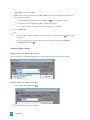
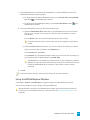
The Explorer Window
Choose View > Window > Explorer to toggle the display of the Explorer window.
Like the Project Media window, you can use the Explorer window to view, preview, and add media files to
your project.
Learning more about the Explorer window
Item Name
Description
Back/Forward
Use the Back and Forward buttons to navigate the folder history.
Address Bar
Displays the path to the current folder.
Tree View
Displays all of the available files and folders where you can find
media files.
Contents Pane
Displays the folders and media files contained in the active folder.
Up
Opens the folder one level above the active folder.
Refresh
Refreshes the contents of the active folder.
If you insert a new CD (or other removable media), click to refresh
the Explorer.
Delete
Deletes the selected folder or file.
Add to Favorites
Adds the selected folder to the Favorites folder in the tree view. The
Favorites folder contains links to folders that you use most often.
Start Preview
Plays the selected media file.
Stop Preview
Stops the playback of the selected media file.
Auto Preview
Automatically preview media files when you click them in the
Explorer window. For more information, see "Previewing media files"
on page 86.
30 CHAPTER 3
Item Name
Description
CD Info
If CD information is not available, you can click this button to
display a dialog box where you can edit the CD information and
submit it for inclusion in the Gracenote Media Database.
Get Media from
the Web
Opens the Get Media from the Web dialog, where you can download
files to use in your project.
Views
Allows you to change the way the files are viewed in the list view.
n Details – Displays the file size, date and when the file was last
created or last modified.
n List – Displays a simple list of the file name of each file in the
Explorer window.
n Thumbnail – Displays the first frame of a video file.
n Regions – Displays any regions that have been defined in the
selected media file.
n Summary – Displays a short description of the selected media
file at the bottom of the Explorer window.
n Tree – Displays all of the available drives and folders that you
may choose from to find files.
n All Files – Displays all file types in the active folder.
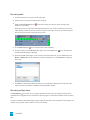
Adding regions from a file to the timeline
When Regions is selected in the Explorer window, any regions saved in the selected file are displayed in the
bottom of the Explorer window.
You can drag a region to the timeline to create an event using a portion of a file.
You can save regions and markers in a media file using the Trimmer window. For more information,
see "Using the Trimmer" on page 150.
Click the down arrow next to the Views button
the Explorer window.
and choose Regions to toggle the display of regions in
Using the Favorites folder
Select the Favorites folder
in the tree view to view the contents of the Favorites folder. This folder
contains shortcuts to folders that you use often.
WINDOW DOCKING AREA AND FLOATING WINDOW DOCKS 31
Favorites are saved in the following file:C:\Users\user name\AppData\Local\Sony\Vegas
Pro\13.0\NewExplorerFavorites.txt.
The file is saved whenever you close the Explorer window or exit the application. You can copy the file
to different computers or user accounts to migrate Favorites settings.
To see this file, you must have the Show hidden files and folders radio button selected on the View
tab of the Folder Options Control Panel.
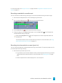
Adding a folder to the Favorites folder
1. Browse to the folder you want to add.
2. Right-click the folder and choose Add Folder to Favorites from the shortcut menu. A shortcut to the
folder is added to the Favorites folder.
Removing a folder from the Favorites folder
1. Select the Favorites folder.
2. Right-click the folder you want to delete and choose Delete from the shortcut menu.
Deleting a folder from Favorites deletes only the shortcut to the folder; the target folder is unaffected.
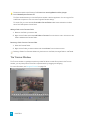
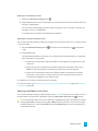
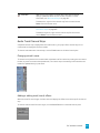
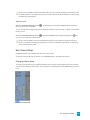
The Trimmer Window
The Trimmer window is a good place to edit any media file. When a media file is placed in the Trimmer
window, you can place portions of the file on separate tracks by dragging and dropping.
For more information, see "Using the Trimmer" on page 150.
32 CHAPTER 3
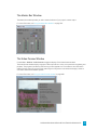
The Master Bus Window
The Master Bus window provides you with a streamlined view of your project's master output.
For more information, see "Using the Master Bus Window" on page 329.
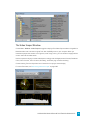
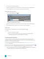
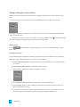
The Video Preview Window
Choose View > Window > Video Preview to toggle the display of the Video Preview window.
The Video Preview window displays a project's video output at the current cursor position during editing and
playback. The playback includes any effects that you have applied to it. This window is also useful when
editing frame by frame for synchronizing audio. Right-click anywhere in the window to display a shortcut
menu with Video Preview window options.
For more information, see "Using the Video Preview window" on page 468.
WINDOW DOCKING AREA AND FLOATING WINDOW DOCKS 33
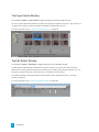
The Project Media Window
Choose View > Window > Project Media to toggle the display of the Project Media window.
You can use the Project Media window to collect and arrange all the media you will use in your project. You
can add media, preview it, view and change file properties, and add effects to a file.
For more information, see "Using the Project Media window" on page 79.
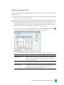
The Edit Details Window
Choose View > Window > Edit Details to toggle the display of the Edit Details window.
The Edit Details window displays a database for all of the media in your project. It shows information
about how files in the project are being used and allows you to modify many of those properties. You may
sort, add or change information, rearrange columns, and edit items in the project.
This window provides an alternate method for working with events, audio CD track lists, commands,
markers, and regions.
For more information, see "Using the Edit Details Window" on page 185.
34 CHAPTER 3
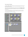
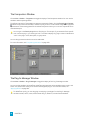
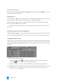
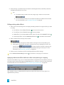
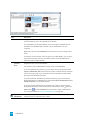
The Transitions Window
Choose View > Window > Transitions to display or hide the Transitions window. Use this window to choose
and preview transition effects that you can use to control how a video event begins or ends, or to change
the way one event flows into another.
The left pane lists each of the available transitions organized in folders. Click the Expand and Collapse buttons to open and close the folders, and select a plug-in name. The thumbnail images in the right pane
represent each of the existing presets for the selected transition. Hover your cursor over a preset to see an
animated example.
You can type in the Search plug-ins box to find plug-ins. For example, if you wanted to find a specific
color-correction plug-in, you could type "color" in the box to display only plug-ins that include the term
"color" in the plug-in name, description, or group name.
For more information, see "Adding transitions" on page 317.
WINDOW DOCKING AREA AND FLOATING WINDOW DOCKS 35
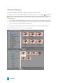
The Video FX Window
Choose View > Window > Video FX to toggle the display of the Video FX window.
The left pane lists each of the available video effects organized in folders. Click the Expand and Collapse
buttons to open and close the folders, and select a plug-in name. The thumbnail images in the right pane
represent each of the existing presets for the selected effect. Hover your cursor over a preset to see an
animated example.
You can type in the Search plug-ins box to find plug-ins. For example, if you wanted to find a specific
color-correction plug-in, you could type "color" in the box to display only plug-ins that include the term
"color" in the plug-in name, description, or group name.
You can drag a preset thumbnail to a track, event, or to the Video Preview window to apply the effect.
For more information, see "Adding video effects" on page 313.
36 CHAPTER 3
The Media Generators Window
Choose View > Window > Media Generators to toggle the display of the Media Generators window. You
can use this window to add text, titles, backgrounds, and other generated media.
The left pane lists each of the available media generators organized in folders. Click the Expand and
Collapse buttons to open and close the folders, and select a plug-in name. The thumbnail images in the
right pane represent each of the existing presets for the selected generator. Hover your cursor over a preset
to see an animated example.
You can type in the Search plug-ins box to find plug-ins. For example, if you wanted to find a specific
color-correction plug-in, you could type "color" in the box to display only plug-ins that include the term
"color" in the plug-in name, description, or group name.
You can drag a preset thumbnail to a track to add media.
For more information about using generated media, see "Adding generated media to your project" on page
322.
WINDOW DOCKING AREA AND FLOATING WINDOW DOCKS 37
The Compositors Window
Choose View > Window > Compositors to toggle the display of the Compositors window. You can use this
window to add compositing effects.
The left pane lists each of the available compositors organized in folders. Click the Expand and Collapse buttons to open and close the folders, and select a plug-in name. The thumbnail images in the right pane
represent each of the existing presets for the selected compositor. Hover your cursor over a preset to see an
animated example.
You can type in the Search plug-ins box to find plug-ins. For example, if you wanted to find a specific
color-correction plug-in, you could type "color" in the box to display only plug-ins that include the term
"color" in the plug-in name, description, or group name.
You can drag a preset thumbnail to a track to add media.
For more information, see "Compositing and masks" on page 383.
The Plug-In Manager Window
Choose View > Window > Plug-In Manager to toggle the display of the Plug-In Manager window.
You can use this window to access effects and effects packages that can be applied to events, tracks, and
busses. This window also allows you to rename and reorganize plug-ins. For more information, see
"Applying effects" on page 299.
To add effects quickly, you can drag plug-ins and plug-in packages from the Plug-In Manager
window to events, tracks, busses, and the Audio Plug-In, Video FX, or Video Preview windows.
38 CHAPTER 3
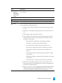
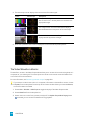
The Video Scopes Window
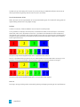
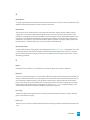
Choose View > Window > Video Scopes to toggle the display of the Video Scopes window in Vegas® Pro.
Broadcast video uses a narrower range of color than the RGB you see on your computer. When you
broadcast a project that contains out-of-gamut (out-of-range) colors, you can introduce image problems
or even noise into the audio stream.
Use the scopes to analyze your video and adjust accordingly with the Brightness and Contrast, Broadcast
Colors, Color Corrector, Color Corrector (Secondary), and Levels plug-ins before rendering.
Choose a setting from the drop-down list to choose which scope you want to display.
For more information, see "Monitoring video with scopes" on page 489.
WINDOW DOCKING AREA AND FLOATING WINDOW DOCKS 39
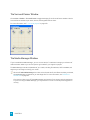
The Surround Panner Window
Choose View > Window > Surround Panner to toggle the display of the Surround Panner window. Use the
Surround Panner window to pan tracks, busses, and assignable effects chains.
For more information, see "5.1 surround projects" on page 433.
The Media Manager Window
If you've installed the Media Manager, you can use it to search for media and manage your collection of
audio and video media so you can find just the right media for your Vegas Pro projects.
The Media Manager maintains a database of your media, including file attributes, ACID metadata, and
tags that you can assign to classify your media.
When the Enable Media Manager check box on the General tab of the Preferences dialog is selected,
the Media Manager will start when you start Vegas Pro. For more information, see "Preferences General Tab" on page 601.
Clear the check box to turn off the Media Manager and prevent it from starting with the application.
If you're not using the Media Manager, you may want to turn it off to conserve processing power or
memory.
40 CHAPTER 3
The XDCAM Explorer Window
Choose View > Window > XDCAM Explorer to toggle the display of the XDCAM Explorer window.
You can use this window to import, manage, and export XDCAM clips.
For more information, see "Using the XDCAM Explorer Window" on page 407.
WINDOW DOCKING AREA AND FLOATING WINDOW DOCKS 41
The Mixing Console Window
Choose View > Window > Mixing Console to display the Mixing Console window.
The Mixing Console window provides an integrated view of all tracks and busses in your project using the
appearance of a traditional hardware-based mixer.
For more information, see "The Mixing Console" on page 345.
The Device Explorer Window
The Device Explorer allows you to browse and import clips from AVCHD, XDCAM EX, NXCAM, XAVC, XAVC
S, Panasonic P2, and RED ONE/EPIC/SCARLET devices; CompactFlash-based memory recording units such
as the HVR-MRC1; and hard-disk-based recording units such as the HVR-DR60.
For more information, see "Using the Device Explorer" on page 100.
42 CHAPTER 3
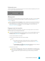
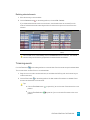
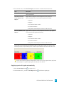
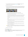
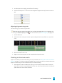
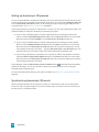
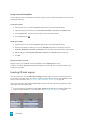
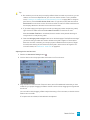
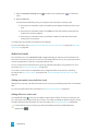
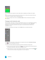
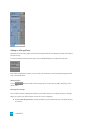
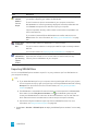
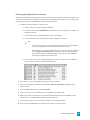
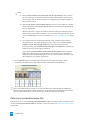
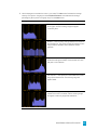
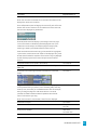
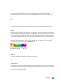
Loudness meters
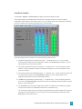
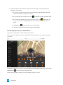
Choose View > Window > Loudness Meters to display the Loudness Meters window.
The Loudness Meters provide data about an audio file's momentary loudness, short-term loudness,
integrated (overall) loudness, and loudness range. You can use these values when mastering for broadcast
to ensure compliance with loudness standards (such as the CALM Act).
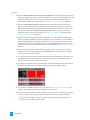
The meters display real-time values for each of the following measurements:
n The M meter represents the momentary loudness — in loudness units (LU) — across all audio
channels based on 400-millisecond integration windows. The Momentary box displays a numeric
representation of the momentary loudness.
n The S meter represents the short-term loudness — in loudness units — across all audio channels
based on 3-second integration windows. The Short box displays a numeric representation of the
short-term loudness.
n The I meter represents the integrated loudness — in loudness units — across all audio channels over
the duration of the program. The Integrated box displays a numeric representation of the
integrated loudness and includes an over-target indicator.
n The LRA meter represents the loudness range — in loudness units — of the momentary and shortterm levels. The Loudness Range measurement provides a standardized method of determining the
dynamic range of the signal.
n The True peaks meter represents the peak levels in dB FS. True peaks are calculated using a higher
sample rate than peaks in the Master Bus window for increased accuracy.
The True Peaks indicator shows you whether the target loudness has been exceeded. The indicator is
reset when you restart playback, or you can right-click the Loudness Meters window and choose
Reset Clip from the shortcut menu.
WINDOW DOCKING AREA AND FLOATING WINDOW DOCKS 43
The statistics on the left side of the window display the last-calculated values and are reset when you restart
playback. You can reset the values by right-clicking the Loudness Meters window and choosing Reset
Metering Engine from the shortcut menu.
Loudness is recalculated whenever you start, stop, seek, or change playback direction. If you want to
force a recalculation, right-click the window and choose Reset Metering Engine from the shortcut
menu.
When the Master bus mode drop-down list on the Audio tab of the Project Properties dialog is set to
5.1 Surround, surround processing is applied when measuring loudness (a gain of ~1.5 dB is applied to
the left and right surround channels). When the Master bus mode drop-down list is set to Stereo, all
channels contribute equally to the loudness measurement.
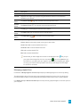
Choosing a metering mode
To change the mode of the meters, choose Options > Loudness Meters, and then choose EBU R 128 Mode
or ATSC A 85 Mode from the submenu (you can also right-click the meter to set its options).
n When using EBU R 128, the target value of the Integrated meter is -23 LUFS, and the maximum
True peak value is -1.0 dB FS. Use this mode when you're mastering to European Broadcasting
Union (EBU) standards.
n When using ATSC A 85, the target value of the Integrated meter is -24 LUFS, and the maximum
True peak value is -2.0 dB FS. Use this mode when you're mastering to North American Advanced
Television Systems Committee (ATSC) standards.
The over-target indicators will be triggered if the target values for Integrated and True Peaks meters are
exceeded.
Choosing a loudness scale
To change the scale of the meter, choose Options > Loudness Meters > Loudness Scale, and then choose
EBU +9 or EBU +18 from the submenu (you can also right-click the meter to set its options).
n When using EBU +9, the meters are displayed with a range of -18 to +9 LU.
n When using EBU +18, the meters are displayed with a range of -36 to +18 LU.
Choosing a wide range allows you to see low-level signals at the expense of precision display at
high levels.
Select Absolute (-23 LUFS) if you want to display loudness values as Loudness Units Full Scale (LUFS).
When Absolute (-23 LUFS) is not selected, all values are expressed as Loudness Units (LU) relative to the
selected mode (EBU R 128 Mode or ATSC A 85 Mode).
44 CHAPTER 3
Configuring peak meters
To toggle the True Peaks meters in the Loudness Meters window, choose Options > Loudness Meters
> Show True Peak Meter (you can also right-click the meter to set its options).
Please note that true peaks are calculated using a higher sample rate than peaks in the Master Bus
window for increased accuracy.
Peak levels may be miscalculated if audio signals are asymmetrical or if a DC offset is present. To enable
filtering, choose Options > Loudness Meters > True Peak Blocking Filter. When True Peak Blocking Filter
is selected, peaks are calculated as the maximum of the filtered and unfiltered signals.
Choosing a wide range allows you to see low-level signals at the expense of precision display at high
levels.
WINDOW DOCKING AREA AND FLOATING WINDOW DOCKS 45
46 CHAPTER 3
Chapter 4
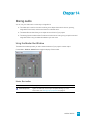
Working with projects
A project (.veg) file saves the relevant information about your source media: file locations, edits, insertion
points, transitions, and effects.
A project file is not a multimedia file. It contains pointers to the original source files, so you can edit your
project nondestructively — you can be creative without worrying about corrupting your source files.
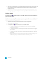
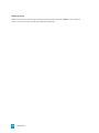
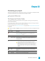
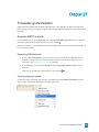
Creating a new project
The first step in creating your masterpiece is to create a Vegas® Pro project file.
You can quickly create a project by clicking the New button on the toolbar. The project will use the
default settings, but you can use the Project Properties dialog to edit the settings later. For more
information, see "Setting project properties" on page 47.
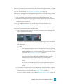
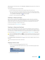
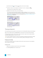
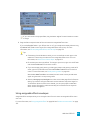
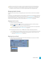
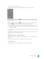
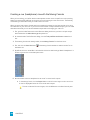
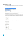
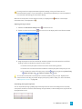
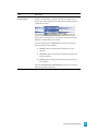
1. From the File menu, choose New. The New Project dialog is displayed.
2. Use the New Project dialog to set your project properties.
3. Click OK to create the project.
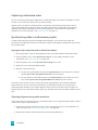
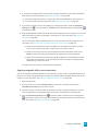
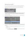
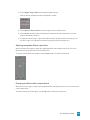
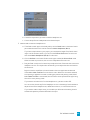
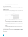
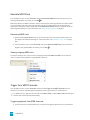
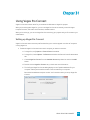
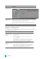
Setting project properties
Use the Project Properties dialog to control the default settings and store information about the current
project.
From the File menu, choose Properties to display the dialog.
Select the Start all new projects with these settings check box to use the current settings whenever a
new project is created.
WORKING WITH PROJECTS 47
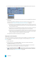
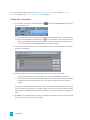
Video
Use the Video tab to adjust the video format of your project. You can also click the Project Video
Properties button on the Video Preview window to display this tab.
Item
Description
Template
Allows you to select a preset template to automatically configure the
controls in the dialog.
You may also manually change the settings and save them as a
custom template for future use. To create a new template, enter a
name in the text box and click the Save Template button . The
new custom template name is added to the drop-down list.
To set your project properties to match the properties of an existing
media file, click the Match Media Settings button
and browse to
the file you want to use.
Width and Height
Determines the frame size of your final movie when rendered. The
maximum frame size for AVI, MPEG, QuickTime, Windows Media,
and still-image output is 2048x2048.
The maximum frame size is 4096x4096.
Field order
Determines field order of the frames when drawn on the screen.
Consult your capture/video output card's documentation for the
proper field order for your specific device.
n None (progressive scan): Select this option when viewing the
video on a computer. This option ignores interlacing.
n Upper field first: Select this option (also called odd or field A)
for video that will be viewed on a television.
n Lower field first: Select this option (also called even or field B)
for DV output or if Upper field first produces jittery or shaky
output.
Pixel aspect ratio
Choose a setting from the drop-down list to change the pixel aspect
ratio of your project. This setting will depend on your capture/video
output card.
Computers display pixels as squares, or a ratio of 1.0. Televisions
display pixels as rectangles (ratios other than 1.0).
Using the incorrect setting can result in distortion or stretching.
Consult your capture/video output card's manual for the proper
settings.
48 CHAPTER 4
Item
Description
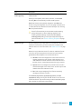
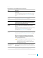
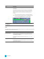
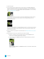
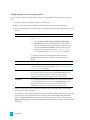
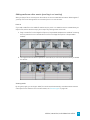
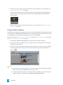
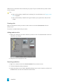
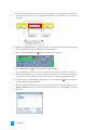
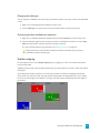
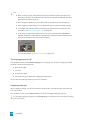
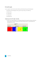
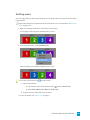
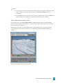
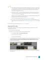
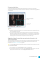
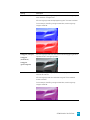
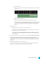
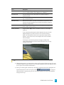
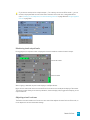
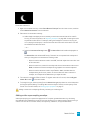
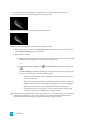
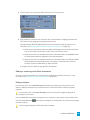
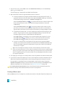
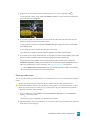
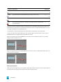
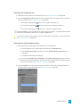
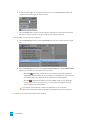
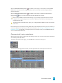
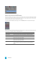
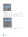
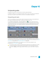
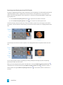
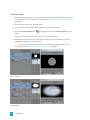
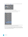
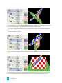
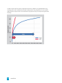
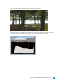
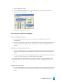
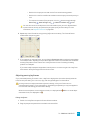
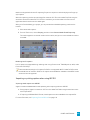
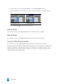
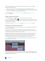
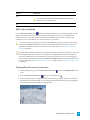
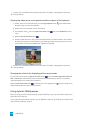
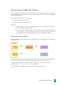
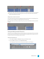
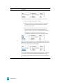
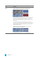
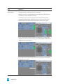
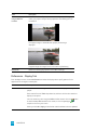
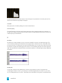
Output rotation
Choose a setting from the drop-down list to rotate your project's
output. Use output rotation to edit projects for display in portrait
(rather than landscape) or inverted orientation:
In this example, the video was shot with the camera tripod rotated 90
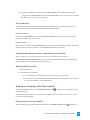
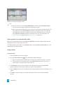
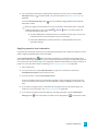
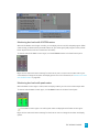
degrees. However, with the project output unrotated, the video is
pillarboxed within the standard landscape frame.
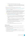
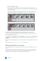
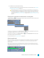
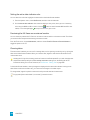
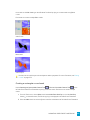
After choosing 90 clockwise° from the Output rotation drop-down
list, the Video Preview window is rotated, and the video fills the
frame.
If you want to rotate a media file's orientation, you can use the
Rotation drop-down list on the Media Properties dialog.
For more information, see "Creating rotated projects" on page 59.
Frame rate
Choose a setting from the drop-down list to change the frame rate of
your project.
The television frame rate in the US, North and Central America, parts
of South America, and Japan (NTSC) is 29.97 frames per second
(fps). In many parts of the world, including Europe and much of
Asia, the television standard is PAL at 25 fps. France, Russia, and
most of Eastern Europe use SECAM, which is a variation on PAL and
also uses 25 fps.
Stereoscopic 3D mode
Choose a setting from the drop-down list to create a stereoscopic 3D
project, or choose Off to create a 2D project.
By default, the project's Stereoscopic 3D mode, Swap Left/Right,
and crosstalk cancellation settings will also be used when previewing
and rendering your project, but you can override the project settings
if necessary.
For more information, see "Setting up your stereoscopic 3D project"
on page 201.
WORKING WITH PROJECTS 49
Item
Description
Pixel format
Choose a setting from the drop-down list to indicate whether you
want to perform video processing (compositing, scaling, previewing,
rendering, and most video plug-ins) using 8-bit or 32-bit, floatingpoint arithmetic.
n 8-bit: Performs video processing using 8-bit arithmetic and in
the video (studio RGB, or 16-235) color space.
n 32-bit floating point (video levels): Performs video
processing using 32-bit arithmetic and in the video color
space.
n 32-bit floating point (full range): Performs video processing
using 32-bit arithmetic and in the full-range color space.
The 32-bit floating point settings allow greater precision for
processing video, but require significantly more processing
power than working with 8-bit video.
Tips:
n 32-bit floating point (video levels) is recommended when
working with 10-bit YUV input/output or when using
xvYCC/x.v.Color media.
n When using 8-bit input/output, the 32-bit floating point
(video levels) setting can prevent banding from compositing
that contains fades, feathered edges, or gradients.
n Video plug-ins and media generators that support floatingpoint processing are included in the 32-bit floating point
folder in the Transitions, Video FX, Media Generators,
Compositors, and Plug-In Manager windows.
n If you're creating a 32-bit project, you can increase
performance during editing and playback by using the 8-bit
setting during editing and switching to 32-bit floating point
(video levels) before rendering.
Compositing gamma
When you choose 32-bit floating point (full range) from the Pixel
format drop-down list, you can choose a compositing gamma value.
n 1.000 (Linear): The default setting when you choose 32-bit
floating point (full range) from the Pixel format drop-down
list.
n 2.222 (Video): Processing in 8-bit video is always performed
using a setting of 2.222.
View transform
50 CHAPTER 4
Choose the reference view transform to use for the project. For more
information, see "Enabling color management in your Vegas Pro
project" on page 428.
Item
Description
Full-resolution
rendering quality
Choose a setting from the drop-down list to set the quality of the
rendered video.
Unless you have specific performance problems, choose Good.
Choosing Best can dramatically increase rendering times.
Good uses bilinear scaling without integration, while Best uses
bicubic scaling with integration. If you're using high-resolution stills
(or video) that will be scaled down to the final output size, choosing
Best can prevent artifacts.
Some file formats allow you to associate a video rendering
quality setting with a custom rendering template. Final
rendering template settings override the Full-resolution
rendering quality setting in the Project Properties dialog. For
more information, see "Custom rendering templates" on page
536.
Motion blur type
Choose a setting from the drop-down list to choose the curve that is
used to blur frames when you add a motion blur envelope to the
video bus track. For more information, see "Video bus track" on page
248.
Motion blurring creates the illusion of motion on individual frames
(much like using a long exposure time) and can make computergenerated animation appear more smooth and natural.
n Gaussian: Gives more weight to the central frame in the blur
and less weight to the outer frames. A bell-shaped curve is
used between the central and outer frames. Gaussian blur is
the best choice in most situations where blurring is required.
n Pyramid: Gives more weight to the central frame in the blur
and the least weight to the outer frames. A linear slope is used
between the central and outer frames.
n Box: Uses an equal weighting for all frames, essentially
averaging the frames in the blur.
The Gaussian (asymmetric), Pyramid (asymmetric), and Box
(asymmetric) settings use only the left half of each curve, from the
central frame back. Asymmetric settings create a hard leading edge
with a trailing blur behind the moving object.
WORKING WITH PROJECTS 51
Item
Description
Deinterlace method
Choose a setting from this drop-down list to determine the method
used to render effects and deinterlace the two fields that make up a
frame.
n None: Performs no deinterlacing.
n Blend fields: Uses contents from both fields and works well
for high-detail, low-motion video.
n Interpolate: Uses a single field at a time and works well for
high-motion, low-detail video.
No deinterlacing occurs in the Draft and Preview video preview
modes. The Good and Best modes apply the selected
deinterlacing method.
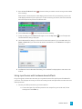
Adjust source media to
better match project or
render settings
Select this check box if you want Vegas Pro to scale images or adjust
interlacing to allow media files to work better with your project.
This setting will correct for the following types of inconsistencies:
n DV media will be cropped for 320x240 Internet renders to
prevent letterboxing.
n DV widescreen media will be cropped in HD projects.
n HD media will be cropped in DV widescreen projects.
n 486-line media will be cropped in 480-line projects.
n 480-line media will be padded in 486-line projects.
When the check box is cleared, source media files are processed with
their native settings.
Prerendered files folder
Prerendered video files are saved to this folder so that you don't need
to rerender the project every time you view it. For more information,
see "Selectively prerender video" on page 481.
If you want to change the location of the folder, click the Browse
button and choose a location. Ideally, this location should be on a
different hard drive than the one where your operating system is
installed.
Prerendered files can consume significant drive space. Select a
folder on an a/v-capable drive with ample free space: DV
requires approximately 228 MB per minute.
Free storage space in
selected folder
52 CHAPTER 4
Displays the total amount of available space on the selected drive.
Audio
Use the Audio tab to change the data format of the current project.
Item
Description
Master bus mode
Choose Stereo from the drop-down list to create a two-channel
stereo project.
Choose 5.1 Surround if you want to perform advanced 5.1-channel
mixing. For more information, see "5.1 surround projects" on page
433.
Number of stereo
busses
Enter the number of stereo busses for the project. For more
information, see "Adding audio busses" on page 332.
Sample rate
Choose a sample rate from the drop-down list or enter a value in the
edit box.
Bit depth
Select a setting from the drop-down list to specify the number of bits
used to store each sample. Higher values will increase the quality of
playback and any recordings that you make.
Resample and stretch
quality
Choose a setting from the drop-down list to determine the accuracy
with which audio files will be resampled to match your project
settings.
The Resample and stretch quality setting also determines the quality
of processing when time-stretching audio events. For more
information, see "Editing event properties" on page 180.
Enable low-pass filter
on LFE
Select this check box if you want to apply a low-pass filter to each
track in a 5.1 surround project that is assigned to the LFE channel. For
more information, see "5.1 surround panning and mixing" on page
436.
Applying a low-pass filter approximates the bass-management
system in a 5.1 decoder and ensures that you're sending only lowfrequency audio to the LFE channel.
Before rendering your surround project, check your surround
authoring application's documentation to determine its required
audio format. Some encoders require a specific cutoff
frequency and rolloff, and your encoder may require that no
filter be applied before encoding.
Cutoff frequency for
low-pass filter
Choose a frequency from the drop-down list or type a frequency in
the box to set the frequency above which audio will be ignored by the
LFE channel.
Low-pass filter quality
Choose a setting from the drop-down list to determine the sharpness
of filter's rolloff curve. Best produces the sharpest curve.
WORKING WITH PROJECTS 53
Item
Description
Recorded files folder
When you record audio tracks, your recorded files are saved in a
single folder.
If you want to change the location of the folder, click the Browse
button and choose a location. Ideally, this location should be on a
different hard drive than the one where your operating system is
installed.
If you have not specified a location, you will be prompted for
the location where you want to save your recorded audio when
you click the Arm for Record button in the track header:
Free storage space in
selected folder
Displays the total amount of available space on the selected drive.
Ruler
Use the Ruler tab to change the format used to display the timeline ruler. Vegas Pro also sends tempo
information to tempo-aware audio plug-ins.
Item
Description
Ruler time format
Choose a setting from the drop-down list to choose how you want
the Time Ruler to be displayed. You can change the format at any
time after project creation.
For more information about each time format, see "Time ruler" on
page 595.
Ruler start time
Enter the desired starting time for the project.
For example, the ruler can be offset to start at 1 hour for timecode
synchronization purposes.
54 CHAPTER 4
Item
Description
Beats per minute
Enter your project tempo in Beats Per Minute.
This tempo is used to determine the scale of the ruler (if you choose
Measures & Beats from the Ruler time format drop-down list) and
to specify the tempo used by the metronome.
Select the Import at project tempo check box on the Audio tab of
the Preferences dialog if you want ACID loops to be stretched to
match the project tempo when you add them to the timeline or
preview from the Explorer window. Clear the Import at project
tempo check box if you want to ignore tempo information.
Beats per measure
Specify the number of beats in each measure.
This tempo is used to determine the scale of the ruler (if you choose
Measures & Beats from the Ruler time format drop-down list) and
to specify the tempo used by the metronome.
Note that gets one
beat
Specify the note that receives one beat. For example, if this value is
four, then a quarter note gets one beat.
This tempo is used to determine the scale of the ruler (if you choose
Measures & Beats from the Ruler time format drop-down list) and
to specify the tempo used by the metronome.
Summary
Item
Description
Title
Enter a title for the project.
Artist
Enter the name of the artist.
Engineer
Enter the name of the person who mixed or edited the project.
Copyright
Enter copyright information for the project.
Comments
Enter any comments you want to associate with the project.
Audio CD
Use the Audio CD tab to configure options for burning disc-at-once CDs. For more information, see "Discat-once (DAO or Red Book) CD Burning" on page 502.
WORKING WITH PROJECTS 55
Item
Description
Universal Product
Code/
Media Catalog Number
Universal Product Codes (UPC) or Media Catalog Numbers (MCN)
can be written to a CD as a means of identification. However, not all
CD-R drives support this feature. Check your CD-R drive
documentation to determine if your drive will write these codes.
Enter the code in this box, and the codes will be written to the CD
along with the rest of the project.
Universal product codes are administered by GS1 US:
http://www.gs1us.org/.
First track number on
disc
Enter a number in the box or to specify the track number of the first
track.
Specifying a value other than one will produce a valid Red Book
CD, but some audio CD players may be unable to play the disc.
Opening a project or media file
From the File menu, choose Open to open a media file or Vegas Pro project.
You can open multiple Vegas Pro projects by launching another instance of the application (if your
computer has enough resources).
n Opening a project closes the current project and displays the opened project in the Vegas Pro
window.
n Opening a media file will place the event that contains the media onto a new track in the
current project.
Opening a Vegas Pro project
1. From the File menu, choose Open. The Open dialog box is displayed.
2. Choose the folder where the project you want to open is stored:
n Choose a drive and folder from the Look in drop-down list.
n Choose a folder from the Recent drop-down list to quickly select a folder from which you
have previously opened files.
56 CHAPTER 4
3. Select a file in the browse window or type a name in the File name box. Detailed information about
the selected file appears at the bottom of the dialog box.
Tips:
n To limit the files displayed in the dialog, choose a file type from the Files of Type dropdown list or enter *. and an extension in the File name box. For example, enter *.wav to
display all wave files in the current folder, or enter *guitar*.wav to display all wave files
that have the word guitar in the file name.
n To open a project quickly, double-click a .veg file in the Explorer window.
4. Click Open. If you have not saved the current project, you will be prompted to save your changes.
Adding a Vegas Pro project to the current project (nesting)
Nesting allows you to add a Vegas Pro project to the timeline of another project. Nesting can help you
organize a timeline or create other effects. For more information, see "Nesting projects" on page 61.
Use nested projects to organize a project that uses extensive compositing.
Perform either of the following actions to nest a Vegas Pro project within the current project:
n Drag a Vegas Pro project from the Explorer window (or Windows Explorer) to the timeline.
n From the File menu, choose Import, then choose Media from the submenu, and then browse to the
project you want to use.
The file is added to the Project Media window and an event is created where you drop the project in the
timeline or at the cursor position before you opened the Import Media dialog.
Opening a media file
1. From the File menu, choose Open. The Open dialog box is displayed.
2. Choose the folder where the file you want to open is stored:
n Choose a drive and folder from the Look in drop-down list.
n Choose a folder from the Recent drop-down list to quickly select a folder from which you
have previously opened files.
WORKING WITH PROJECTS 57
3. Select a file in the browse window or type a name in the File name box. Detailed information about
the selected file appears at the bottom of the dialog box.
To limit the files displayed in the dialog, choose a file type from the Files of Type drop-down
list or enter *. and an extension in the File name box. For example, enter *.wav to display all
wave files in the current folder, or enter *guitar*.wav to display all wave files that have the word
guitar in the file name.
If you want to use RAW camera files in your project, the Microsoft Camera Codec Pack will
allow you to view RAW camera files and add them to the timeline. For more information, see
http://www.microsoft.com/download/en/details.aspx?id=26829.
4. Click Open.
5. The file is added to the Project Media window and an event is created. The event is created at the
cursor position in the selected track, or a new track will be created if no tracks of the appropriate
type exist. For example, if your current project contains three audio tracks when you open an AVI
file, a video track will be created for the AVI.
Opening a still-image sequence
If you've exported a video clip as a still-image sequence using another application (a 3D-rendering
application, for example), you can add the sequence to the Vegas Pro timeline as a single event.
1. From the File menu, choose Open. The Open dialog box is displayed.
2. Choose the folder where the sequence you want to open is stored:
n Choose a drive and folder from the Look in drop-down list.
n Choose a folder from the Recent drop-down list to quickly select a folder from which you
have previously opened files.
3. Select the first image in the sequence (or the image you want to use to start the event). Detailed
information about the selected file appears at the bottom of the dialog box.
4. Select the Open sequence check box.
5. In the Last image box, type the number of the last image you want to open. For example, if you'd
selected AnimationOne_00001.tga in step 3, you could type 120 in this box to create a new event
using AnimationOne_00001.tga to AnimationOne_00120.tga.
6. Click Open to display the Media Properties dialog, where you can view or edit information about the
sequence. For more information, see "Viewing or changing media file properties" on page 105.
7. Click OK. A new event is created at the cursor position in the selected track (a new track will be
added if no track is selected). Each image in the sequence will be displayed for one frame.
58 CHAPTER 4
Opening a CD Architect version 4 project
If you have existing CD Architect version 4 projects, you can use Vegas Pro to open your project files and
create Red Book CDs.
1. From the File menu, choose Open. The Open dialog box is displayed.
2. Choose the folder where your CD Architect project file (.cdp) is stored:
n Choose a drive and folder from the Look in drop-down list.
n Choose a folder from the Recent drop-down list to quickly select a folder from which you
have previously opened files.
3. Select a project file in the browse window or type a name in the File name box.
4. Click Open. If you have not saved the current project, you will be prompted to save your changes.
For more information about creating Red Book CDs, see "Disc-at-once (DAO or Red Book) CD
Burning" on page 502.
Creating rotated projects
The use of rotated displays — monitors that display vertical media — has become increasingly popular:
you can see them in kiosks, presentations, and even on the nightly news. If you have a project that you'd
like to display in a rotated format, Vegas Pro makes it easy.
WORKING WITH PROJECTS 59
1. Create a new project.
2. Set your project properties as needed, and then choose a setting from the Output rotation dropdown list to indicate the orientation of your destination display device. If you want to display your
project in portrait (tall) mode, choose 90° clockwise or 90° counterclockwise. For more information,
see "Setting project properties" on page 47.
In this example, the video was shot with the camera tripod rotated 90 degrees. However, because
neither the project or the media has been rotated, the video is displayed sideways within the
standard landscape frame.
After choosing 90° clockwise from the Output rotation drop-down list, the Video Preview window is
rotated. Because the media hasn't been rotated yet, it doesn't match the project orientation and is
letterboxed within the frame.
3. Add your media files to your project. For more information, see "Adding media files to your project"
on page 87.
4. Edit the properties for each of your media files to set its rotation as needed:
a. Right-click a media file in the Project Media window and choose Properties from the
shortcut menu. The Media Properties dialog is displayed.
b. Choose a setting from the Rotation drop-down list to indicate the direction you want to
rotate your media.
After choosing 90° clockwise from the Rotation drop-down list, the media is rotated, and the
video fills the frame.
60 CHAPTER 4
c. Click OK to close the Media Properties dialog and save your changes.
To rotate multiple files quickly, select them in the Project Media window, right-click a
selected file, and then choose Rotate 90° Clockwise or Rotate 90° Counterclockwise
from the shortcut menu.
5. Drag your clips from the Project Media window to the timeline to create events.
6. Edit your project as needed. For more information, see "Editing events on the timeline" on page 131.
7. Render your project to any supported rendering format. For more information, see "Rendering
projects (Render As)" on page 523.
In the Render As dialog, select the Use project output rotation setting check box if you want to use
the Output rotation setting from the Project Properties dialog for your rendered file. When the
check box is cleared, the media is rotated according to its Media Properties setting, but the project
itself is unrotated—you can use this setting to proof your project on an unrotated display.
To render a portrait-oriented file for viewing on a computer without a rotated display, you can
create a rendering template that matches the proportions of your project. For more
information, see "Custom rendering templates" on page 536.
a. Right-click the Video Preview window and ensure Simulate Device Aspect Ratio is selected.
b. Next, adjust the size of the Video Preview window to match the frame size you'd like to
render and note the Display dimensions in the lower-right corner of the Video Preview
window.
c. From the File menu, choose Render As, choose the desired rendering format from the Save
as type drop-down list, and then choose a rendering template that's close to the frame size
you noted in step b. Windows Media Video is a good choice.
d. Click the Custom button, and then use the Video tab in the Custom Template dialog to
adjust the frame size to match the dimensions you noted in step 7b.
e. Save your template for later use.
f. Clear the Use project output rotation setting check box and render your file.
Nesting projects
Nesting allows you to add a Vegas Pro project to the timeline of another project. Nesting can help you
organize a timeline or create other effects:
n Create a single element — such as a lower-third graphic or watermark — that you can use in
multiple timeline locations or projects.
n Create a complex composited element that you can use as a single media object in the timeline. For
more information, see "Compositing video" on page 383.
n Create a transition across multiple events by placing the events in a nested project and applying a
transition to the nested project event.
WORKING WITH PROJECTS 61
n Create a musical composition with its own tempo and FX bus structure that you can use in another
project.
n Create a separate project for each scene in a video and nest those projects in a master video project.
You can apply color correction to each shot within the scene and then apply color correction to the
entire scene in the master project.
n Use master projects to deliver a single project in multiple formats without time- and disk-consuming
intermediate renders: for example, you could add your 24p, 16:9 HD (high-definition) project to a
master project to reformat the project as widescreen SD (standard definition) for DVD, letterboxed
SD for VHS, 4:3 pan-and-scan SD, or 25p.
Perform either of the following actions to nest a Vegas Pro project within the current project:
n Drag a Vegas Pro project from the Explorer window (or Windows Explorer) to the timeline.
n From the File menu, choose Import, then choose Media from the submenu, and then browse to the
project you want to use.
The file is added to the Project Media window and an event is created where you drop the project in the
timeline (or at the cursor position if import or use the Explorer to open a project file).
You can edit the nested project's events just like any other event on the timeline: trim, shuffle, stretch, crop,
or apply event switches.
For more information, see "Editing events on the timeline" on page 131.
Notes:
n The output from the nested project's master bus is used to create the audio event. If you nest a 5.1
surround project, the audio event will be a stereo downmix of the surround master bus. For more
information, see "5.1 surround projects" on page 433.
n Audio events from nested projects cannot be edited in a sound editor. For more information, see
"Opening events in an audio editor" on page 178.
n The audio from a nested project will require that a proxy file be built. To avoid building proxy files,
delete audio from nested projects and use the master project to create your audio.
From the Tools menu, choose Rebuild Offline Nested Audio to rerender any offline audio proxy
files in your project. Audio proxy files can be offline if you cancel rendering when adding a nested
project.
n Markers and regions in the nested project are displayed in the timeline as media markers in the
event. For more information, see "Using media markers and regions" on page 220.
n Prerendered video from a project will be used when that project is nested in another project's
timeline.
n You can edit a nested project by right-clicking the event in the timeline and choosing Edit Source
Project from the shortcut menu. A new Vegas Pro window will open to allow you to edit the project.
For more information, see "Project references in rendered files" on page 65.
62 CHAPTER 4
Opening a recent project
A list of recently used project files is maintained at the bottom of the File menu. Choosing a project from
this list allows you to quickly return to work on that project.
You can use the General tab in the Preferences dialog to turn the recently used file list on or off and to
specify how many files should be displayed. For more information, see "Preferences - General Tab" on page
601
Saving a project
From the File menu, choose Save to save changes to the current Vegas Pro project (.veg). When a Vegas Pro
project is saved, all of the layout of tracks, envelope adjustments, effects parameters, etc. are saved in this
project file.
The first time you save a project, the Save As dialog is displayed.
If you want to keep the previous version of your project before you made changes, use the Save As
command to save the new version of the project with a new name. For more information, see "Saving
and renaming a project (Save As)" on page 63.
Automatic project saving
A backup copy of your project is automatically saved every five minutes. If your system crashes, you will be
prompted to open the backup file the next time you start the application.
Backup files are saved in the location specified in the Temporary files folder box on the General tab of the
Preferences dialog. Files are saved with the .autosave.veg extension and are deleted when you exit the
application. For more information, see "Preferences - General Tab" on page 601.
If you prefer not to autosave your project, you can clear the Enable autosave check box on box on the
General tab of the Preferences dialog.
When you save a project, .veg.bak files are created in your project folder to allow you to return to the
project's last-saved state. Creation of backup files is independent of automatic project saving.
Saving and renaming a project (Save As)
From the File menu, choose Save As to save the current project to a different location or with a new name.
1. From the File menu, choose Save As.
2. Select the drive and folder where you want to store the project.
3. Type a name in the File Name box.
WORKING WITH PROJECTS 63
4. From the Save as Type drop-down list, choose the format in which you want to save the project.
Extension
Format Name
Description
.veg
Vegas Pro
project
This option saves the references to media files used in the
project. Also saved is project information, track effects,
envelopes, bus assignments, and output properties. The .veg
file does not combine events into a single file.
.txt
EDL text file
This option creates a text version of event placements in the
track view. This text description can then be imported into a
database or text application for modification or other
purposes.
.aaf
Edit Protocol
Compliant AAF
File
.aaf
Avid Legacy
AAF File
These options create AAF (Advanced Authoring Format) files
that you can use to exchange projects between applications.
For example, if your postproduction facility uses a tool
other than Vegas Pro software, you could provide your
project as an AAF file.
For more information, see "Importing and exporting AAF
files" on page 70.
5. Select the Copy media with project check box if you want to create copies of each of the project's
media files in the same location as the project file. This allows you to collect all of a project's assets
in a single location.
6. Click the Save button.
7. If you selected the Copy media with project check box, a dialog is displayed to allow you to specify
how you want to copy media files:
n Select the Copy source media radio button to copy the entire source media files to your
project folder.
Any project media files from folders outside the project folder are copied to the project
folder. Media files that are saved in folders below the project folder are not copied.
n Select the Create trimmed copies of source media radio button and enter a value in the
Extra head and tail box to reduce the number and size of media files necessary to represent
your project.
Your project will be scanned to determine how much of each media file is being used and
those regions will be rendered to new media files. The amount of time specified in the Extra
head and tail setting will be added before and after the media file to allow subsequent edits.
All events are then updated to point to the new files. Finally, inactive takes are removed from
the project, and the project is saved.
64 CHAPTER 4
The newly rendered files will match the source files' properties as closely as possible:
n Audio/video events are saved in a new AVI file. You can trim DV AVI, uncompressed
AVI, and Sony YUV AVI files. Because of the lossy nature of other video formats, those
video files will not be trimmed, but will simply be copied to the project folder.
n Audio-only events will be rendered to the Wave format if under 2 GB (or Wave64 if
over 2 GB), and DV files will be rendered as DV AVI files.
Project references in rendered files
When your Vegas Pro project uses media that was rendered with an embedded project path reference, you
can easily open the source project in the associated application if you need to edit the media later. ACID
5.0, Sound Forge 8.0, and Vegas Pro 6.0 and later allow you to save the project path reference when you
render files.
For example, imagine that you have an audio file on the Vegas Pro timeline that was rendered from an
ACID project. In previewing your Vegas Pro project, you discover that you'd accidentally rendered your
ACID project with a critical track muted. You could simply right-click the event on the Vegas Pro timeline
and choose Edit Source Project from the shortcut menu to reopen your ACID project, unmute the track,
and then rerender it.
The project information in the rendered file is a reference to a project file only. If you modify the
project file after rendering, the project data will no longer match the rendered file. To edit a project
using a path reference, the project file and all media must be available on your computer.
Saving the project path in the rendered file
1. Save your Vegas Pro project. The project must be saved before you can embed the project reference
in the rendered file.
2. Perform the procedure described in the Rendering Projects topic to choose the file type and location
for rendering your files, and select the Save project as path reference in rendered media check
box.
For more information, see "Rendering projects (Render As)" on page 523.
The check box will be unavailable if you haven't saved your project or if you're rendering using
a third-party file-format plug-in.
Editing a referenced project
1. Perform one of the following actions:
n Right-click a media file in the Explorer window.
n Right-click a media file in the Project Media window.
n Right-click an event on the timeline.
WORKING WITH PROJECTS 65
2. From the shortcut menu, choose Edit Source Project. An ACID, Vegas Pro, or Sound Forge window
will open with the source project.
To edit a source project using a computer other than the computer where the project was
created, the editing computer must meet the following requirements:
n The software that was used to create the project must be installed and the project file
extension (.acd, .acd-zip, .veg, .vf, or .frg) must be registered on the editing computer.
n The editing computer must have the same version (or later) of the software that was used to
create the project.
n The project file must exist on the editing computer using the same file path as on the
computer where the project was created.
n The project's source media must exist on the editing computer. If the media files do not use
the same file path as on the computer where the project was created, you will be prompted
to choose a new folder or replacement files.
3. Edit the project as necessary.
4. Render the edited project using the same name as the original media file and close the editing
application.
If you're editing an existing track, your project will automatically be updated to use the latest
rendered media file.
Sharing a project online
From the File menu, choose Share Online and then follow the on-screen instructions to choose a publishing
provider and save your current project to the Web so you can share it with others.
Uploading your movie to YouTube
When you're done with your movie, you're probably going to want to share it with your friends and family
as soon as possible.
This feature requires that you have a YouTube account. If you don't already have an account, you can
go to http://www.youtube.com/signup to sign up.
1. From the File menu, choose Upload to YouTube. The Upload to YouTube dialog is displayed.
2. Type your YouTube username and password in the YouTube username and YouTube password
boxes.
If you have a Gmail address linked with your YouTube account, you can use your Gmail
username and password to log in.
3. Type a title to identify your video in the Title box.
The information from the Title box of on the Summary tab of the Project Properties dialog is used
by default.For more information, see "Setting project properties" on page 47.
66 CHAPTER 4
4. Type a description of your movie in the Description box.
The information from the Comments box on the Summary tab of the Project Properties dialog is
used by default.
5. Choose a setting from the Video category drop-down list. The category you choose is used to
classify videos on the YouTube site.
6. Type keywords you want to associate with your movie in the Tags box. Use words that relate to your
movie and describe its content. These tags will be used when searching YouTube. Use commas to
separate multiple keywords.
If you are uploading a stereoscopic 3D project, Vegas Pro automatically adds the tags needed
to enable 3D viewing on YouTube. For more information, see "Stereoscopic 3D editing" on
page 201.
7. Select the Public or Private radio button to set broadcast options for your movie. Public videos can
be seen by any YouTube user; private videos can be seen only by members you specify.
8. Select the Normal or Higher radio button to set the video quality for your movie. The Higher setting
creates better-looking video for broadband connections but will take longer to render.
The estimated file size is displayed at the bottom of the dialog.
9. Select the Render and upload loop region only check box if you want to save only the portion of the
project that is contained within the loop region. Loop Playback does not need to be selected for this
option to work.
10. Click the Upload button to start uploading your movie to YouTube.
After your movie has been uploaded, you can click the Edit Video Info button to display the My
Account page in a browser window, where you can edit the information about your video, or click
Close to return to the Vegas Pro timeline.
Videos you upload to YouTube are transcoded after uploading and are not immediately
available. You can visit the My Videos page on the YouTube Web site to check the status of
your uploaded videos.
WORKING WITH PROJECTS 67
Importing and exporting projects
Project-interchange tools add flexibility to your workflow, allowing you to exchange projects with other
popular editing platforms.
Importing a project
1. From the File menu, choose Import, and then choose a project type from the submenu:
n AAF: imports an AAF file from an edit protocol compliant AAF, Avid ProTools, or Avid Media
Composer. For more information, see "Importing and exporting AAF files" on page 70.
n Premiere/After Effects (*.pproj): imports an Adobe Premiere or After Effects project.
n Final Cut Pro 7/DaVinci Resolve (*.xml): imports an XML file from Apple Final Cut Pro 7 or
DaVinci Resolve.
n Final Cut Pro X (*.fcpxml): imports an XML file from Apple Final Cut Pro X.
n EDL Text File (*.txt): imports an EDL text file. For more information, see "Edit Decision Lists"
on page 76.
The Import dialog is displayed.
2. Choose the folder where the project you want to open is stored:
n Choose a drive and folder from the Look in drop-down list.
n Choose a folder from the Recent drop-down list to quickly select a folder from which you
have previously opened files.
3. Select a file in the browse window or type a name in the File name box.
4. Click Open.
If elements in the project could not be imported, a report is displayed.
Exporting a project
1. From the File menu, choose Export, and then choose a project type from the submenu:
n Pro Tools AAF File (*.aaf): exports your project to an AAF file for use in Avid Pro Tools. For
more information, see "Importing and exporting AAF files" on page 70.
n Media Composer AAF (*.aaf): exports your project to an AAF file for use in Avid Media
Composer. For more information, see "Importing and exporting AAF files" on page 70.
n Premiere/After Effects (*.pproj): exports your project for use in Adobe Premiere or After
Effects project.
n Final Cut Pro 7/DaVinci Resolve (*.xml): exports your project to an XML file for use in Apple
Final Cut Pro 7 or DaVinci Resolve.
68 CHAPTER 4
n Final Cut Pro X (*.fcpxml): exports your project to an XML file for use in Apple Final Cut Pro
X.
n EDL Text File (*.txt): exports your project to an EDL text file. For more information, see "Edit
Decision Lists" on page 76.
The export dialog is displayed.
2. Choose the folder where you want to export the project:
n Choose a drive and folder from the Look in drop-down list.
n Choose a folder from the Recent drop-down list to quickly select a folder from which you
have previously opened files.
3. Type a name in the File name box.
4. Click Save.
If elements in the project could not be exported, a report is displayed.
WORKING WITH PROJECTS 69
Importing and exporting AAF files
You can use AAF (Advanced Authoring Format) files to exchange projects between applications. For
example, if your postproduction facility uses a tool other than Vegas Pro, you could provide your project as
an AAF file.
Creating an AAF file
If you intend to export your project as an AAF file, please note the following usage guidelines and plan your
project accordingly:
n Audio and video cuts are preserved.
n Track-based audio gain and panning are preserved when saving or importing AAF files.
Select the AAF Export - Use clip-based audio envelope check box on the General tab of the
Preferences dialog if you want to combine track and event gain envelopes and save them as clipbased gain envelopes in the AAF file. When the check box is cleared, track envelopes are saved as
track envelopes, and event envelopes are saved as clip envelopes. For more information, see
"Preferences - General Tab" on page 601.
When exchanging AAF with another application, refer to its documentation to determine whether
audio gain and panning changes are supported.
n Muted audio tracks are not included in the AAF file.
n When you import an AAF file, the track- and clip-based gain envelopes are combined and imported
as track envelopes.
n Audio and video effects are ignored.
n All video transitions are exported as AAF Video Dissolve transitions.
n All audio crossfades are exported as AAF Mono Audio Dissolve transitions.
n Time-stretched video is exported using the AAF "Video Speed Control" effect.
n Time-stretched audio is not supported: audio events that are time stretched will play at their original
speed, and time is added to the track to represent the stretched duration; audio events that are time
compressed will play at the original speed, but the event is trimmed to match the compressed event
length.
n Any track that has mono and stereo audio will be ignored; the AAF format does not allow mono and
stereo audio on a single track.
n Still images will be exported as 1,080,000 frames (the AAF specification does not allow media with
a length and frame rate of 0).
n Track order in your exported AAF will not match your Vegas Pro project: in the Vegas Pro track
model, the first track represents the foreground; in the AAF specification, the first track represents
the background.
70 CHAPTER 4
n Audio is exported using frame units when the AAF Export - Use frame unit for audio check box is
selected on the General tab of the Preferences dialog. Clear the check box if you want to use sample
units for exported audio (use this setting only if your project contains audio only or if you know the
application that will import your AAF supports frame units for video and sample units for audio).
For more information, see "Preferences - General Tab" on page 601.
1. From the File menu, choose Export, and then choose Pro Tools AAF File or Media Composer AAF
File from the submenu. The export dialog is displayed.
2. Select the drive and folder where you want to store the project.
3. Type a name in the File name box.
4. Click Save.
Importing an AAF file into the current project
If you intend to import an AAF file into a Vegas Pro project, please note the following usage guidelines and
plan your project accordingly:
n Audio and video cuts are preserved.
n Track-based audio gain and panning are preserved when saving or importing AAF files.
When you import an AAF file, the track- and clip-based gain envelopes are combined and imported
as track envelopes.
When exchanging AAF with another application, refer to its documentation to determine whether
audio gain and panning changes are supported.
n All video transitions are imported as crossfades.
n Audio and video effects are ignored.
n The AAF Video Speed Control effect is preserved and mapped to the Playback rate setting in the
imported event's properties. For more information, see "Editing event properties" on page 180.
n If you import an AAF file that has embedded wave or AIFC audio, the files will be extracted to the
same folder as the AAF file when you import the project.
1. From the File menu, choose Import, and then choose AAF from the submenu. The Import dialog is
displayed.
2. Choose the folder where the project you want to open is stored:
n Choose a drive and folder from the Look in drop-down list.
n Choose a folder from the Recent drop-down list to quickly select a folder from which you
have previously opened files.
3. Select a file in the browse window or type a name in the File name box.
4. Click Open. The AAF is imported into the current project.
WORKING WITH PROJECTS 71
Importing an AAF file into a new Vegas Pro project
If you intend to import an AAF file into a Vegas Pro project, please note the following usage guidelines and
plan your project accordingly:
n Audio and video cuts are preserved.
n Track-based audio gain and panning are preserved when saving or importing AAF files.
When you import an AAF file, the track- and clip-based gain envelopes are combined and imported
as track envelopes.
When exchanging AAF with another application, refer to its documentation to determine whether
audio gain and panning changes are supported.
n All video transitions are imported as crossfades.
n Audio and video effects are ignored.
n The AAF Video Speed Control effect is preserved and mapped to the Playback rate setting in the
imported event's properties. For more information, see "Editing event properties" on page 180.
n If you import an AAF file that has embedded wave or AIFC audio, the files will be extracted to the
same folder as the AAF file when you import the project.
1. From the File menu, choose Open. The Open dialog is displayed.
2. Choose the folder where the project you want to open is stored:
n Choose a drive and folder from the Look in drop-down list.
n Choose a folder from the Recent drop-down list to quickly select a folder from which you
have previously opened files.
3. Select a file in the browse window or type a name in the File name box.
4. Click Open. If you have not saved the current project, you will be prompted to save your changes.
72 CHAPTER 4
Archiving projects
Choose File > Export >Vegas Project Archive to export your project and its associated media.
1. Choose File > Export >Vegas Project Archive. The Vegas Project Archive dialog is displayed.
2. Use the Vegas Project Archive dialog to choose options for saving your archive:
a. In the Project file box, choose the folder and file name you want to use to save your archive.
b. Select the Include nested projects check box if you want to include nested projects in the
archive.
c. Select the Include media if you want to copy media files with the archive.
d. Select the Include video proxy/audio peak files check box if you want to include audio
peaks and audio/video proxy files with the archive. For more information, see "Rebuild audio
peaks" on page 188 or "Creating proxy files for high-definition editing" on page 102.
e. Select the Exclude unused media if you want to skip archiving unused media files. If you
clear the check box, all project media will be archived.
3. Click the Finish button to create your project archive.
Working with P2 Video
The following steps will guide you through the process of using P2 video in your Vegas Pro project.
1. Shoot your video with a P2 camera.
2. Start a new Vegas Pro project, and set your project properties to the format that most closely
matches your desired output format (or use the Match Media Video Settings button
in the
Project Properties dialog to match an existing media file).
For more information, see "Setting project properties" on page 47.
3. Use the Device Explorer window to import your P2 files.
For more information, see "Using the Device Explorer" on page 100.
4. Drag your clips from the Project Media window to the timeline to create events.
5. Edit your project as needed.
If you're working on a system with limited processing power, converting to a lower-resolution
format will streamline the editing process and allow you to preview your project with higher
frame rates. This process is called proxy editing.
For more information, see "Creating proxy files for high-definition editing" on page 102.
6. Render your project to any supported rendering format.
If you want to render to P2 format and export the rendered file to a P2 camera, please use the following
steps:
WORKING WITH PROJECTS 73
1. Verify that your Vegas Pro project is set match your P2 file settings.
2. From the File menu, choose Render As.
3. In the Render As dialog, choose Panasonic P2 MXF in the Output Format box.
4. Use one of the following templates, or select a template and click the Customize Template button
to edit its settings.
If you use the Custom Template dialog to customize your rendering template, leave all settings at
their default values except for the Frame size control.
5. Use the Output File controls to choose where the files will be rendered. The P2 file format has strict
file-naming requirements, so when you render P2 files, you choose an output folder rather than
rendered file names.
Click the Browse button to choose where you want to render:
n To render to a P2 camera that's connected to your computer, choose the CONTENTS folder on the
camera's memory card.
n To render to a folder on your computer, choose a folder. If a P2-format CONTENTS folder exists in
the selected folder, Vegas Pro will use the existing folder structure. If no P2-format
CONTENTS folder exists, Vegas Pro will create all necessary files and folders
File names are automatically incremented when you render. For example, if the highest-numbered
clip in the selected render folder is ..\CONTENTS\VIDEO\00036R.mxf, the next file you render to
that folder will be created as ..\CONTENTS\VIDEO\0004xx.mxf.
File naming is an important part of the P2 file specification. Do not change the file names in a
P2 CONTENTS folder.
Exporting a movie to a PSP™
Do you want to be able to fit your movie in the palm of your hand?
Choose File > Export> PSP™ (PlayStation®Portable) to convert your project to Sony AVC (*.mp4) format
and transfer it to a USB-connected PSP™ system.
Notes:
n PSP™ firmware version 2.0 or later is required to use this feature. To check your firmware
version, choose Settings > System Settings > System Information on the PSP™ system. For
the latest firmware, go to http://us.playstation.com (in the United States) or
http://www.playstation.com (outside the United States).
n Full-screen and high-bit-rate rendering templates require the latest PSP™ firmware for
playback.
n If you're using high-resolution video, choose Best from the Full-resolution rendering quality
drop-down list on the Video tab of the Project Properties dialog before exporting your movie to
prevent resizing artifacts.
74 CHAPTER 4
1. Click in the timeline to position your cursor on the frame you want to use to represent your movie.
This image will be displayed as a thumbnail on the PSP™ navigation system.
2. Connect the USB cable and AC adapter to the PSP™ system and place it in USB mode.
3. Choose File > Export> PSP™ (PlayStation®Portable). The Export to PSP™ (PlayStation®Portable)
dialog is displayed.
If you want to render an AVC video without transferring to a PSP™, use the Render As dialog
and choose Sony AVC (*.mp4) in the Output Format box. For more information, see "Rendering
projects (Render As)" on page 523.
4. The Title box displays the title of your project from the Summary tab of the Project Properties
dialog. This title will be displayed on the PSP™ system.
Editing the title in the Export to PSP™ (PlayStation®Portable) dialog will also update the Project
Properties dialog.
5. The File path box displays the folder and file name that will be used to render your movie.
Click the Refresh button if you need to rescan the device.
6. Choose a setting from the Template drop-down list to specify the settings that will be used to save
your file.
You can choose to encode with QVGA, QVGA widescreen, PSP™ full-screen, or standard-definition
NTSC frame aspect.
n Both QVGA settings create 320x240 video, but the widescreen templates use anamorphic
widescreen encoding, which is properly decoded on the PSP™ system.
n The PSP™ full-screen templates create 480x270 video to match the PSP™ screen resolution.
n The SD NTSC templates create 720x480 video to match a standard-definition NTSC screen.
Tips:
n The settings for the selected template are displayed in the Description box.
n The 512 Kbps QVGA and PSP™full-screen templates are useful when you want to
minimize file size, and the 896- and 1128- Kbps templates will produce higher-quality
video, especially in scenes with high-motion video.
7. Select the Render loop region only check box if you only want to render a portion of your project. If
the check box is cleared, the entire project will be rendered to a new file.
The check box is available only if you've created a time selection in the timeline.
8. Select the Stretch video to fill output frame size (do not letterbox) check box if you want to
reformat your video so it fills the output frame size listed in the Description box.
When the check box is cleared, the current aspect ratio is maintained and black borders are added
to fill the extra frame area (letterboxing). This option is useful when the desired output format does
not match the frame aspect ratio of your project.
WORKING WITH PROJECTS 75
9. Select the Use project output rotation setting check box if you're rendering a rotated project and
want to use the Output rotation setting from the Project Properties dialog for your rendered file.
When the check box is cleared, the media is rotated according to its Media Properties setting, but
the project itself is unrotated—you can use this setting to proof your project on an unrotated
display.
For more information, see "Creating rotated projects" on page 59.
10. Click OK. Your movie file (<filename>.MP4) and thumbnail file (<filename>.THM) are created and
transferred to the appropriate folder on the PSP™ system.
Edit Decision Lists
An Edit Decision List (EDL) is a text summary of a project. An EDL lists of all of the media files used, where
they are placed on the timeline, and how they are trimmed.
Vegas Pro EDLs are not the same as those used in traditional linear editing suites and are not intended as a
project interchange for other editing applications.
Because of the significant differences between editing applications, projects that are converted from EDLs
(or exported to EDLs) are necessarily simplified. Events are inserted into the timeline on a single track, and
transition effects from the other application are replaced with crossfades. Projects that are imported from
another application's EDL are initially limited to four audio tracks. If you add more tracks, save the project
as a .veg file.
Creating an EDL
1. From the File menu, choose Export > EDL Text File (*.txt). The export dialog is displayed.
2. Select the drive and folder where you want to store the project.
EDL files do not contain information about the location of source media. Save the .txt file in
the same folder as the source media.
3. Type a name in the File name box.
4. Click OK.
Opening an EDL
1. From the File menu, choose Import > EDL Text File (*.txt). The import dialog is displayed.
2. Choose the folder where the project you want to open is stored:
n Choose a drive and folder from the Look in drop-down list.
—or—
n Choose a folder from the Recent drop-down list to quickly select a folder from which you
have previously opened files.
3. Select a file in the browse window or type a name in the File name box.
76 CHAPTER 4
4. Click Open. If you have not saved the current project, you will be prompted to save your changes.
Events are placed in the Vegas Pro timeline. All transitions are replaced with crossfades. You can
change the crossfades to other transition types if desired. For more information, see "Automatic
crossfades" on page 136.
Closing a Project
From the File menu, choose Close to close the current project. If you have not saved the project since
changes were last made, a dialog appears asking if you want to save your changes.
n Click No if you want to close the project without saving it.
n Click Yes to save your changes.
n Click Cancel to return to your current project.
Use the Save As command to save your project under a different name or file type. For more
information, see "Saving and renaming a project (Save As)" on page 63.
Exiting the Vegas Pro Application
From the File menu, choose Exit to close the application and return to your desktop.
If you have not saved the current project since changes were last made, a dialog appears asking if you
want to save your changes.
n Click No if you want to exit without saving your project.
n Click Yes to save your changes.
n Click Cancel to return to the Vegas Pro window and your current project.
Use the Save As command to save your project under a different name or file type. For more
information, see "Saving and renaming a project (Save As)" on page 63.
WORKING WITH PROJECTS 77
78 CHAPTER 4
Chapter 5
Adding, managing, and arranging media
After you've created a project, you're going to need to add media to it.
The objects you work with in Vegas® Pro projects are referred to as media files and events:
n Media files are the source audio and video files that are stored on your hard disk. Vegas Pro projects
do not operate on or modify these files. Files can be accessed from the Explorer window.
n An event is an occurrence of a media file on the Vegas Pro timeline. An event can represent an
entire media file or a portion of it. A single media file can be used repeatedly to create any number
of different events, since each event can be trimmed independently. An event's position on the
timeline determines when it will be played back in your project.
Using the Project Media window
Choose View > Window > Project Media to toggle the display of the Project Media window.
You can use the Project Media window to collect and arrange all the media you will use in your project. You
can add media, preview it, view and change file properties, and add effects to a file.
Adding media files to the Project Media window
Files are added to the Project Media window when you open media files, import media, or add media files
to the timeline using the Explorer.
You can also drag the files to the Project Media window from the Vegas Pro Explorer or Windows Explorer.
To add media files from external sources, use the buttons in the Project Media toolbar:
Item
Description
Import Media: click to add a media file to your project without adding it to
the timeline.
Capture Video: click to start the video capture application specified on the
Video tab of the Preferences dialog.
For more information, see "Capturing video" on page 117.
ADDING, MANAGING, AND ARRANGING MEDIA 79
Item
Description
Extract Audio from CD: click to extract a track from an audio CD.
For more information, see "Extracting audio from CDs" on page 127.
Vegas Pro is not intended, and should not be used for, illegal or
infringing purposes, such as the illegal copying or sharing of copyrighted
materials. Using Vegas Pro for such purposes is, among other things,
against United States and international copyright laws and contrary to
the terms and conditions of the End User License Agreement. Such
activity may be punishable by law and may also subject you to the
breach remedies set forth in the End User License Agreement.
Get Media from the Web: click to open the Get Media from the Web dialog,
where you can download files to use in your project.
Cleaning the Project Media list
Click the Remove All Unused Media from Project button
on the timeline.
to remove any files that have not been used
Removing a media file from the project
Click the Remove Selected Media from Project button
Project Media window and project.
to remove all selected media files from the
If a file is in use by an event on the timeline, you will be prompted to delete the event.
Viewing or editing file properties
Click the Properties button to display the Properties dialog for the selected media file. For more
information, see "Viewing or changing media file properties" on page 105.
In most cases, you will not need to edit file properties. However, adjusting the Field Order setting for video
files can help correct jitter when you output your project to a television monitor.
Tagging media files
Use the Media Tags panel in the Project Media window to add tags to your media files. To show or hide the
Media Tags panel, click the down arrow next to the Views button
and choose Media Tags.
80 CHAPTER 5
When you add tags to media files, media bins are created for each tag under the "Tags" folder. For more
information, see "Sorting your media with bins" on page 103.
Adding tags
1. Select one or more media files in the Project Media window.
2. Type the tag text in the Add tags box.
3. Press Enter to add the tag to the media files.
You can also add tags using keyboard shortcuts. For more information, see "Creating Quick Tags" on
page 81.
Removing tags
1. Select one or more media files in the Project Media window.
2. Press Backspace in the Add tags box to remove tags from the media files.
You can also click the "x" in the tag icon to remove a tag from a media file:
Creating Quick Tags
Quick Tags allow you to assign tags to keyboard shortcuts that you can use to quickly add tags to media
files.
1. Select one or more media files in the Project Media window.
2. Type the tag text in the Add tags box.
3. Press Ctrl+Shift and the number you want to assign for the shortcut. For example, press Ctrl+Shift+1
to assign the tag text to the Ctrl+1 shortcut.
4. Press Enter to add the tag to the media files.
ADDING, MANAGING, AND ARRANGING MEDIA 81
Editing Quick Tags
Right-click the Quick Tags area and choose Edit Quick Tags to display the Edit Quick Tags dialog. You can
use this dialog to edit the text of existing Quick Tags or create new Quick Tags.
Configuring 24p pulldown removal
Right-click a DV AVI file in the Project Media window and choose File Format Properties from the shortcut
menu to edit file settings from the file format plug-in associated with the media file type.
For 24p NTSC DV AVI files with 2-3 pulldown, you can use this dialog to configure removal of pulldown
fields.
In most cases, you will not need to edit pulldown removal settings. However, if the settings were not
properly set in the DV header when your video was captured, you can fine-tune pulldown removal without
recapturing your video.
1. Right-click an AVI file in the Project Media window and choose File Format Properties from the
shortcut menu. The AVI/DV Media Properties dialog is displayed.
This command is not available for clips that are not AVI or DV or those that use 2-3-3-2 pulldown.
2. Select the Enable 2-3 pulldown removal check box.
You can clear this check box if you want to override pulldown removal for individual files when
the Allow pulldown removal when opening 24p DV check box is selected on the General tab of
the Preferences dialog.
3. Choose a setting from the Starting frame timecode offset drop-down list to indicate what
timecode numbers represent which frame in the video sequence.
For example, if you have an NTSC DV file with 2-3 pulldown created on a Sony JH3 HDCAM deck,
the default settings for timecode offset use 0 for the Starting frame timecode offset.
If you have changed the timecode offsets on the deck (or if you have material with pulldown from
another source) you will have to experiment with the settings to determine the correct offset.
4. Check for interlacing:
a. In the Project Properties dialog, choose a NTSC DV 24p template from the Template dropdown list. For more information, see "Setting project properties" on page 47.
b. Choose the Best (Full) setting in the Video Preview window to show full frames.
c. Step though the clip and look for interlace lines in moving objects or backgrounds.
d. If you see interlace lines, repeat from step 3 and choose a different offset value.
e. When no interlace lines appear, the offset is set correctly.
82 CHAPTER 5
Adding effects to a media file
Click the Media FX button to add an effect to every occurrence of the selected media file in your project
(the source media file is not affected).
Media FX are used for video files only. For more information about adding video effects, see "Adding video
effects" on page 313.
Previewing a media file
Select the media file you want to preview.
n Click the Start Preview button
n Click the Stop Preview button
n Select the Auto Preview button
to begin previewing the media file.
to stop previewing the media file.
to automatically preview a media file when you click it.
Pairing two media files as a stereoscopic 3D subclip
If you have two files that have synchronized timecode — such as video shot on a 3D camera that creates
separate left- and right-eye clips — you don't need to align the audio and video. Just select the clips in the
Project Media window and choose Pair as Stereoscopic 3D Subclip from the shortcut menu.
If you view the clip properties for the new subclip, you'll see that the Stereoscopic 3D Mode is set to Pair
with next stream.
For more information, see "Stereoscopic 3D editing" on page 201.
Changing the appearance of the Project Media window
Click the Views button
window:
and choose a setting from the menu to change the display of the Project Media
Item
Description
List
Displays a simple list of the file name of each file in the Project
Media window.
Details
Displays a list of each file in the Project Media window and a
spreadsheet that displays information about the media file:
You can control the information that is displayed by right-clicking the
Project Media window and choosing View from the shortcut menu. A
list of the available fields is displayed in the shortcut menu.
Specific fields can be hidden by dragging them off of the Project
Media window.
The data fields are listed along the top of the Project Media window
and can be reordered by dragging them. Click on the tabs along the
top to sort the data in ascending or descending order.
ADDING, MANAGING, AND ARRANGING MEDIA 83
Item
Description
The Comments field can be used to add notes about a file in the
Project Media window. Double-click the field to enter text. This
information is saved with the project and is not saved with the media
file itself.
Depending on your current time ruler format, you may see
inconsistencies in the timecode values for clips that you
captured. Video Capture uses SMPTE drop time (29.97 fps). If
you switch the time format to SMPTE drop time in the Vegas
Pro window, the same timecode information will be displayed in
the Video Capture and Vegas Pro windows.
Thumbnail
Displays the first frame of a video file.
Media Tags
Shows or hides the Media Tags panel. For more information, see
"Tagging media files" on page 80.
Recapturing video
If you've captured video files from a DV device using Video Capture, you can recapture your clips from the
Vegas Pro window if the media files are deleted.
If a media file cannot be found, any events that refer to the file will display Media Offline, and the clip will
be displayed with a generic icon in the Project Media window (if you're using the Thumbnail view).
Select the clips that you want to recapture. Right-click a clip and choose Recapture from the shortcut
menu. Video Capture starts in batch capture mode to recapture the clips.
Depending on your current time ruler format, you may see inconsistencies in the timecode values for
clips that you captured. Video Capture uses SMPTE drop time (29.97 fps). If you switch the time to
SMPTE drop time in the Vegas Pro window, the same timecode information will be displayed in the
Video Capture and Vegas Pro windows.
84 CHAPTER 5
Replacing a media file
You can replace a file in the Project Media window with a different file. Replacing a media file updates
every occurrence of the event to use the new media file contents.
1. Right-click a file in the Project Media window, and choose Replace from the shortcut menu. The
Replace Media File dialog is displayed.
2. In the Replace Media File dialog, select the file that you want to use in place of the current file.
3. Click the Open button. The file is replaced in the Project Media window, and every occurrence of the
event is updated to use the new media file contents.
Creating video proxy files
Right-click a video file and choose Create Video Proxy to create a proxy file (.sfvp0) alongside the original
video file. Proxy files are smaller and faster to work with on the timeline. For more information, see
"Creating proxy files for high-definition editing" on page 102.
Using bins to sort your media
Media bins are folders within projects that you can use to organize your media files. For more information,
see "Sorting your media with bins" on page 103.
Selecting all events that refer to a specific media file
Right-click a file in the Project Media window and choose Select Timeline Events from the shortcut menu.
The cursor moves to the first event that uses the media, the timeline scrolls to the cursor, and all events that
use the selected media file in the active take are selected. For more information, see "Using takes as
alternate versions of events" on page 171.
Hold Ctrl or Shift while choosing Select Timeline Events from the shortcut menu to add the events to the
current selection.
Tips:
n When multiple events are selected, press Ctrl+[ or Ctrl+] to move the edge of the previous or next
selected event.
n When multiple events are selected, press Ctrl+Shift+[ or Ctrl+Shift+] to create a time selection from
the previous or next selected event.
ADDING, MANAGING, AND ARRANGING MEDIA 85
Matching project video settings to a media file
Right-click a file in the Project Media window and choose Match Project Video Settings to update your
project video settings to match the selected file.
If you choose a Vegas Pro project (.veg) file, Vegas Pro will match the settings of the project, not the
media within the project.
For more information, see "Setting project properties" on page 47.
Previewing media files
You can preview media files from the Explorer window or Project Media window before placing them in
your project. When you preview a file, the signal is sent to the Preview bus in the Master Bus window.
Previewing a media file
1. Select a media file in the Vegas Pro Explorer or Project Media window.
2. Click the Start Preview button
3. Click the Stop Preview button
previewing the file.
to preview the file.
, select a different file, or place the file in the project to stop
Tips:
n To automatically preview selections when you click a media file in the Explorer or
Project Media window, select the Auto Preview button
click the Auto Preview button again.
. To turn off Auto Preview,
n Video is previewed in the Trimmer window. If you want to preview in the Video Preview
window, right-click the Trimmer window and deselect the Show Video Monitor
command. For more information, see "Using the Trimmer" on page 150.
For more information, see "Using the Video Preview window" on page 468.
86 CHAPTER 5
Adjusting audio preview volume
The Preview control in the Master Bus window allows you to view and adjust the playback volume level. If
the control is not visible, choose Mixer Preview Fader from the View menu.
Item
Description
Fader
Drag the fader to adjust the playback volume while previewing the
audio file.
Meter
Displays the playback level.
Right-click and choose a command from the shortcut menu to adjust
the range of the meter, reset clip indicators, or hold peaks/valleys.
Adding media files to your project
After you've previewed files to determine which media files you want to use in your project, there are several
ways you can add them to your project.
The volume for new audio tracks is determined by your default track properties. For more information,
see "Setting default track properties" on page 252.
ADDING, MANAGING, AND ARRANGING MEDIA 87
Notes:
n Select the Allow pulldown removal when opening 24p DV check box on the General tab of the
Preferences dialog if you want to remove pulldown when you open 24 fps progressive-scan DV
video files. When the check box is cleared, 24p video will be read and edited as 29.97 fps
interlaced video (60i). For more information, see "Preferences - General Tab" on page 601.
n Select the Import audio at project tempo check box on the Audio tab of the Preferences
dialog if you want ACID loops to be stretched to match the project tempo (specified on the
Ruler tab of the Project Properties dialog) when you add them to the timeline or preview from
the Explorer window. Clear the Import at project tempo check box if you want to ignore
tempo information. For more information, see "Preferences - Audio Tab" on page 618 and
"Setting project properties" on page 47.
n When you add a multichannel audio file (.wav/.wav64, .avi, .mxf, ATRAC, and BWF) to your
project, the audio is added across tracks. For example, if you import a four-channel WAV file,
the audio will be added to four adjacent tracks. For control over which channels are used by
each event, right-click a multichannel audio event, choose Channels from the shortcut menu,
and choose a command from the submenu. For more information, see "Audio channels" on
page 177.
n When you add a multistream audio file to your project, you can choose which stream you
want to use by right-clicking the event, choosing Stream from the shortcut menu, and then
choosing a stream from the submenu.
n 5.1-channel audio from DVD camcorders will be downmixed to stereo when importing into a
stereo project. When importing into a 5.1 surround project, audio will be added to separate
tracks for the center, front, rear, and LFE channels.
n If Vegas Pro cannot read frames in a video event, they will be displayed in red in the timeline
(those frames will be black in the Video Preview window and the rendered output):
n If you want to use RAW camera files in your project, the Microsoft Camera Codec Pack will
allow you to view RAW camera files and add them to the timeline.
n The first time you add video media to the timeline, Vegas Pro will ask you whether you want to
match your project video settings to match the first video media you add to the timeline.
If you choose a Vegas Pro project (.veg) file, Vegas Pro will match the settings of the
project, not the media within the project.
88 CHAPTER 5
Using the Windows Explorer to add media and create events
If you're using the Windows Explorer to browse your computer for media, you can add a media file quickly
by dragging it to the Vegas Pro window.
The media file is added to the Project Media window, and an event is created where you drop the file. If you
drop the file on an area of the timeline that does not contain a track, a new track will be created.
Using the Vegas Pro Explorer to add media and create events
If you're using the Vegas Pro Explorer to preview files, you can add media by performing either of the
following actions:
n Double-click a media file or Vegas Pro project to add it to your project. The file is added to the
Project Media window, and an event is created at the cursor position.
n Drag a media or project file from the Vegas Pro Explorer to the timeline. The file is added to the
Project Media window, and an event is created where you drop the file.
Tips:
n To add multiple files to the timeline, Ctrl+click (or Shift+click) to select the files and drag them
to the timeline or track list.
n Drag a .veg file to the timeline to add it to the current project as a nested project. For more
information, see "Nesting projects" on page 61.
n Double-click a .veg file in the Explorer window to open a project.
n To add a track from an audio CD, browse to your CD drive and double-click a .cda file (or drag
it to the timeline). You will be prompted to type a name for the file, and then the track will be
extracted. After the track is extracted, it will be added as an event on an audio track in your
project.
To get CD information from Gracenote, browse to the CD and click the CD Info button
in
the Explorer window. For more information, see "Obtaining CD information" on page 128.
n If you're adding video files to the timeline, you can choose to add only the audio or video
stream to your project. Right-click and drag the files to the timeline. When you drop the files, a
shortcut menu is displayed. Choose Audio Only or Video Only from the shortcut menu and
choose a command from the submenu to arrange the event on the timeline.
Vegas Pro is not intended, and should not be used for, illegal or infringing purposes, such as the illegal
copying or sharing of copyrighted materials. Using Vegas Pro for such purposes is, among other
things, against United States and international copyright laws and contrary to the terms and
conditions of the End User License Agreement. Such activity may be punishable by law and may also
subject you to the breach remedies set forth in the End User License Agreement.
ADDING, MANAGING, AND ARRANGING MEDIA 89
Adding multiple files and creating events
If you're using the Explorer or Project Media window, you can add several media files to your project at
once.
1. Select the media files or Vegas Pro projects you want to use.
2. Right-click the selected files and drag them to the timeline. A shortcut menu is displayed.
3. Choose a command from the shortcut menu to indicate how you want to arrange the events on the
timeline.
Command
Description
Add Across Time
Adds the selected media files end-to-end on the track where you drop
them.
Select the Automatically overlap multiple selected media
when added check box on the Editing tab of the Preferences
dialog if you want to overlap events when you add them to the
same track. Automatic Crossfades must be turned on to use
this feature. For more information, see "Preferences - Editing
Tab" on page 626 and "Automatic crossfades" on page 136.
To change the amount of overlap between events, adjust the
Amount setting in the Cut-to-overlap conversion section of the
dialog.
Add Across Tracks
Adds the selected media files as events on adjacent tracks.
Add As Takes
Adds the selected media files as multiple takes of the same event. For
more information about choosing takes, see "Using takes as alternate
versions of events" on page 171.
Video Only
If you're dragging video files to the timeline, you can choose to add
only the video stream to your project. Choose Video Only from the
shortcut menu and choose a command from the submenu to
indicate how you want to arrange the events on the timeline.
Audio Only
If you're dragging video files to the timeline, you can choose to add
only the audio stream to your project. Choose Audio Only from the
shortcut menu and choose a command from the submenu to
indicate how you want to arrange the events on the timeline.
4. Events are created where you drop the files (and the media files are added to the Project Media
window if you're using the Explorer).
The order of the events is determined by file that you click before dragging and the order of the files
in the Explorer or Project Media window: for example, select the files A.wav, B.wav, and C.wav.
Right-click B.wav and drag the files to the timeline. When the shortcut menu is displayed, choose
Add Across Time. When you drop the files, B.wav will be added as the first event, followed by A.wav
and C.wav.
90 CHAPTER 5
Adding media over other events (punching-in vs. inserting)
When you drop a file on a blank spot on the timeline, an event is created at that location. What happens if
you drop a file on an existing event? You can either punch-in or insert an event.
Punch-in
If you add a media file in the middle of another event, a punch-in is created: an event is created where you
drop the file, and the new event simply lies on top of any existing events on the track.
1. Drag a media file from the Vegas Pro Explorer or Project Media window to the middle of an existing
event (or position the cursor and double-click a file in the Vegas Pro Explorer or Project Media
window).
2. The original event maintains its position on the timeline, but cuts to the new event where you added
the new file:
Inserting media
By using auto ripple, you can drop a media file in timeline and automatically move downstream events to
make space for the new event. For more information, see "Post-edit ripple" on page 146.
ADDING, MANAGING, AND ARRANGING MEDIA 91
1. Select the Auto Ripple button
.
2. Drag a media file from the Vegas Pro Explorer or Project Media window to a position on the
timeline between two events (or position the cursor and double-click a file in the Vegas Pro Explorer
or Project Media window).
If you want to insert an event in the middle of an existing event, you can split the existing event
before adding the media file. For more information, see "Splitting events" on page 148.
3. When you add the file, the events to the right move to make space for the new event:
Using the Project Media window to add media without creating events
You can use the Project Media window to collect and arrange all the media you will use in your project
before creating events on the timeline.
From the File menu, choose Import, and then choose Media from the submenu (or click the Import Media
button
in the Project Media window) to add a media file to your project without adding it to the
timeline.
When you're ready to start adding events, you can drag media files from the Project Media window to the
timeline.
For more information, see "Using the Project Media window" on page 79.
Adding layered PSD files to the timeline
You can add layered PSD files to the Vegas Pro timeline, with each layer of the file being an event on its
own track.
These events are just like other events in Vegas Pro software. For example, you could use track motion to
move layers individually, use parent tracks to group and move layers together, apply track effects to
animate just one layer of the graphic, or you could replace a layer with a video.
92 CHAPTER 5
1. Select a layered PSD file in the Explorer or Project Media window.
2. Right-click and drag the file to the timeline.
3. When you release the mouse button, a shortcut menu is displayed. Choose Add Across Tracks to
import the PSD layers across tracks in the timeline.
The PSD layers, including the composite layer, are now available as streams. You can change an
event’s stream by right-clicking an event, choosing Stream from the shortcut menu, and then
choosing the stream you want to use for the event.
Creating a picture slideshow
If you want to create a slideshow using your photos or other still images, Vegas Pro makes it a breeze.
1. Set the duration you want each photo to be displayed on screen.
a. From the Options menu, choose Preferences.
b. Click the Editing tab.
c. In the New still image length box, type the number of seconds you'd like each photo to be
displayed in your movie.
For example, if you wanted each photo to be displayed for three seconds with a one-second
crossfade between photos, choose 5 seconds.
If you have 40 images that you want to display during a three-and-a-half-minute song,
choose 5.25 (210 seconds divided by 40 images).
d. Click OK to close the Preferences dialog.
2. If you want to automatically add crossfades between events when you add them to the timeline,
you can configure cut-to-overlap conversion:
a. From the Options menu, choose Preferences.
b. Click the Editing tab.
c. Select the Automatically overlap multiple selected media when added check box.
d. In the Cut-to-overlap section of the tab, type the desired fade length in the Amount
(seconds) box.
For example, if you'd set the New still image length setting to 5 in the previous step and set
the Amount (seconds) setting to 1, dragging three still images to the timeline would create
three five-second events with one second of overlap between them.
3. Click OK to close the Preferences dialog.
4. Select the files you want to use in the Project Media or Explorer window. For more information, see
"Adding media files to your project" on page 87.
5. Drag the files to a video track.
ADDING, MANAGING, AND ARRANGING MEDIA 93
6. If you want to use transitions between events, drag a preset from the Transitions window to the
overlapping area between two events. For more information, see "Adding transitions" on page 317.
7. For added interest, you can use event panning and cropping and keyframes add motion to your
images. For example, you could pan across an image or zoom in to simulate camera motion.
a. Click the Pan/Crop button
on an event. The Event Pan/Crop dialog is displayed.
b. Verify the Lock Aspect Ratio button
is selected on the left side of the dialog, and then
right-click the image on the right side of the dialog and choose Match Output Aspect from
the shortcut menu. This sets the crop area to match your output frame proportions.
c. Click the First Keyframe button
to move the cursor in the keyframe controller (at the
bottom of the dialog) to the beginning of the event.
d. Adjust the selection rectangle to change the viewable portion of the event. A keyframe is
created to store your crop settings at that point.
e. Click the Last Keyframe button
to move the cursor in the keyframe controller (at the
bottom of the dialog) to the end of the event.
f. Adjust the selection rectangle to change the viewable portion of the event. A keyframe is
created at the end of the event.
When you play back your project, the viewable portion of the image will be animated
between the first and last keyframe settings. For example, if the crop rectangle in the first
keyframe matches the image size (no cropping) and the crop rectangle in the last keyframe
is small, you'll create an animated zoom effect.
For more information, see "Panning and cropping video events" on page 275 and "Keyframe
animation" on page 293.
8. Add an audio file to an audio track to set your slideshow to music.
Importing media from a project file
From the File menu, choose Import, and then choose Media from Project from the submenu to add media
from another Vegas Pro project file to your project.
Using this feature, you can create small, template projects to streamline frequent editing tasks.
Generated media and offline media files are not imported.
1. From the File menu, choose Import, and then choose Media from Project from the submenu. The
Import Media dialog box is displayed.
2. Choose the folder where the file you want to open is stored:
n Choose a drive and folder from the Look in drop-down list.
n Choose a folder from the Recent drop-down list to quickly select a folder from which you
have previously opened files.
3. Select a file in the browse window or type a name in the File name box.
94 CHAPTER 5
4. If you want to import the project's media bins, select the Import bins check box. For more
information, see "Sorting your media with bins" on page 103.
Select the Merge with existing bins check box if you want to merge the imported project's bins with
the current project. When the check box is cleared, a bin is created using the imported project's
name, and the project's bins are imported inside that bin.
5. Click Open.
6. The project's media is added to the Project Media window. For more information, see "Using the
Project Media window" on page 79.
Importing Broadcast Wave Format files
You can use Broadcast Wave Format (BWF) files to exchange audio between audio editors or broadcasting
platforms.
Broadcast Wave Format files are similar to standard .wav files, but they contain additional metadata
including timestamps that tell the software where to add audio on the Vegas Pro timeline.
You can also add Broadcast Wave Format files to your project by dragging them from the Explorer
window to the timeline. However, if you drag a BWF file to the timeline, events are created where you
drop the file. Using the Import Broadcast Wave dialog ensures that events are arranged according to
the timestamps in the file.
1. From the File menu, choose Import, and then choose Broadcast Wave Format from the submenu.
The Import Broadcast Wave Format dialog is displayed.
2. Choose the folder where the project you want to open is stored:
n Choose a drive and folder from the Look in drop-down list.
n Choose a folder from the Recent drop-down list to quickly select a folder from which you
have previously opened files.
3. Select the files you want to open in the browse window.
Information about the selected files is displayed at the bottom of the Import Broadcast Wave
dialog.
ADDING, MANAGING, AND ARRANGING MEDIA 95
4. From the Arrange drop-down list, choose a setting to indicate how you want to arrange audio
events on the timeline:
Setting
Description
Add across tracks
A separate track is created for each BWF file you import.
Add across time
All selected BWF files are added to a single track.
Audio from multichannel BWF files is always added across tracks, regardless of the Arrange
setting. For example, if you import a four-channel BWF file, the audio will be added to four
adjacent tracks. For control over which channels are used by each event, right-click a
multichannel audio event, choose Channels from the shortcut menu, and choose a command
from the submenu. For more information, see "Audio channels" on page 177.
5. If you chose Add across tracks in step 4, choose a setting from the Order tracks drop-down list to
indicate how you want to arrange the tracks in the track list:
Setting
Description
By timestamp
Sorts tracks chronologically using the timestamp in each file.
Select a file in the Import Broadcast Wave dialog to display its
timestamp at the bottom of the dialog.
Alphabetically by
filename
Sorts tracks alphabetically using the names of the files you import.
6. Choose a setting from the Positioning drop-down list to indicate where imported audio will be
added to the timeline.
Setting
Description
Use ruler time
Adds each imported file to the Vegas Pro timeline at the exact
position indicated by its timestamp. For example, if you import a
BWF file with a timestamp of 00:00:30;00, the media would be
added to the timeline at the thirty-second mark on the ruler.
Relative to cursor
Adds each imported file to the Vegas Pro timeline and offsets the
timestamp value by the cursor position. For example, if you position
the cursor at 00:00:10;00 before importing a BWF file with a
timestamp of 00:00:30;00, the media would be added to the timeline
at the forty-second mark on the ruler.
7. Click Open. The selected files are imported and added to the timeline of the current project.
96 CHAPTER 5
Importing video from a DVD camcorder
From the File menu, choose Import, and then choose DVD Camcorder Disc from the submenu to import
video from a finalized Sony DVD Handycam® camcorder disc.
Notes:
n Before importing video, you'll need to finalize the disc. For information about finalizing a disc,
please refer to your camcorder's documentation.
n 5.1-channel audio will be downmixed to stereo when importing into a stereo project. When
importing into a 5.1 surround project, audio will be added to separate tracks for the center,
front, rear, and LFE channels.
1. Place the DVD you want to import in your computer's DVD drive or connect your camcorder to your
computer via USB.
The Sony Handycam USB driver that is included with DVD-based camcorders can prevent
Vegas Pro from recognizing a USB-connected camera. If you use the Add/Remove Programs
Control Panel to uninstall the "Sony DVD Handycam USB driver" component, Vegas Pro will be
able connect to the camera and import video.
2. From the File menu, choose Import, and then choose DVD Camcorder Disc from the submenu. The
Import DVD Camcorder Disc dialog is displayed.
3. From the Source drop-down list, choose the disc that contains the video you want to import.
4. The Destination box displays the folder where the video will be imported. The folder name is based
on the disc's volume label.
Click the Browse button if you want to choose a different folder.
5. Click the OK button to start importing video.
After importing is complete, the video from the disc is added to the Project Media window. Each
chapter is imported as a separate file.
You can then add the imported video to your project just like any other media file. For more
information, see "Adding media files to your project" on page 87.
ADDING, MANAGING, AND ARRANGING MEDIA 97
Editing video from an XDCAM Station with StreamChase
XDCAM Station StreamChase allows you to edit XDCAM clips while they are still being ingested into the
XDCAM Station device from an XDCAM optical disc or live-feed sources such as SDI. XDCAM clips from the
XDCAM Station can also be imported after they have been ingested to the XDCAM Station.
When an MXF file is imported during ingest to the XDCAM Station device, only the material that has
already been ingested will be imported. The clip’s length can be updated during ingest by right-clicking the
clip in the Project Media window and choosing Refresh. Refreshing the clip length allows you to work with
the most recent material available.
The following formats are supported for StreamChase on the Sony XDS-PD2000 device:
n 1080i 35, 50Mb
n 720p 50Mb
n IMX 50Mb
1. Begin ingesting a clip on the XDCAM Station device.
2. Import the clip into your Vegas Pro project:
n From the File menu, choose Import > Media, and then browse to the clip you want to
import.
n Using Windows Explorer or the Vegas Pro Explorer window, drag a clip from the XDCAM
Station to the Vegas Protimeline.
An event is created on the timeline and the clip is added to the Project Media window.
In the Project Media window, clips that are currently being ingested are displayed with an orange
indicator:
After the clip is imported into the project and added to the timeline, it can be played, edited, and
exported just like any other video clip.
98 CHAPTER 5
3. While the clip is ingesting, refresh the file to work with the most recent material available. To update
the clip's length, right-click it in the Project Media window and choose Refresh from the shortcut
menu. For more information, see "Using the Project Media window" on page 79.
Notice that the clip's Length value (displayed at the bottom of the Project Media window) increases
each time the clip is refreshed during ingest if new media is available.
New, usable media is made available periodically by the XDCAM Station device. This is
dependent on the media format being ingested, but most media formats can be refreshed at
ten-second intervals. Refreshes performed between these intervals will result in no visible
update to the media in Vegas Pro.
The new clip length will be reflected in the Trimmer window if the clip is loaded. For more
information, see "Using the Trimmer" on page 150.
Additionally, if one or more events from the clip have been added to the timeline, the event length in
the timeline can be extended to use the available material:
a. Drag the right edge of the event to the right past the clip length. A notch is displayed in the
event to represent the end of the clip:
If you want to create a placeholder event, drag past the end of the clip length. When the clip
is refreshed, the notch will move to show the new end of the clip, and the event will be filled
with updated video.
Notes:
o The image displayed after the notch will be either a loop of the existing media
or a still frame of the last frame of video depending on the Enable looping on
events by default setting on the Editing tab of the Preferences dialog. For more
information, see "Preferences - Editing Tab" on page 626.
o The in point for placeholder event segments must always start at or before the
last frame of the existing media. Placeholder events cannot be created for
media that has not been ingested. For example, you cannot create a
placeholder with an in point 30 seconds after the current end of the available
media.
o If a you split a placeholder event, the in point of the placeholder segment on
the right side of the split will begin at the end frame of the currently available
media.
b. If you want to resize the event to the current media length, drag the right edge of the event
back to the notch to set the event length. If Enable Snapping is selected, the event edge will
snap to the notch. For more information, see "Enable snapping" on page 137.
For more information about adjusting events, see "Adjusting an event's length" on page 158.
ADDING, MANAGING, AND ARRANGING MEDIA 99
4. Continue to edit your project, refreshing StreamChase clips as needed. For more information, see
"Editing events on the timeline" on page 131.
Clips that are refreshed after they have been ingested by the XDCAM Station are displayed with a
green indicator, and the Length value at the bottom of the Project Media window represents the
final clip length:
5. Render your project to your required output format. For more information, see "Rendering projects
(Render As)" on page 523.
Using the Device Explorer
The Device Explorer allows you to browse and import clips from AVCHD, XDCAM EX, NXCAM, XAVC, XAVC
S, Panasonic P2, and RED ONE/EPIC/SCARLET devices; CompactFlash-based memory recording units such
as the HVR-MRC1; and hard-disk-based recording units such as the HVR-DR60.
For more information, see "Working with AVCHD video" on page 419,"XDCAM EX workflow" on page 405,
and "Working with RED camera clips" on page 417.
1. Choose View > Window > Device Explorer. The Device Explorer window is displayed.
2. Connect your camera to a USB port on your computer. The camera is displayed on the left side of
the Device Explorer window.
3. Select your camera on the left side of the Device Explorer window. The camera's clips are displayed
on the right side of the window, and clips that have not yet been imported are indicated with a
yellow icon .
Tips:
n If you want to use clips from a folder on your computer, right-click the left pane of the Device
Explorer window and choose Browse from the shortcut menu.
n In order for some devices to appear in the Device Explorer window, you may need to change
the device's USB Connect setting from Automatic or MTP to Mass Storage.
100 CHAPTER 5
Previewing clips
Select your camera on the left side of the Device Explorer window. The camera's clips are displayed on the
right side of the window, and clips that have not yet been imported are indicated with a yellow icon .
If the Auto Preview button
is selected, you can click a clip in the Device Explorer to audition it. You can
stop the preview by clicking the Stop Preview button , or you can turn off the preview feature by
deselecting the Auto Preview button.
Video is previewed in the Trimmer window. If you want to preview in the Video Preview window, rightclick the Trimmer window and deselect the Show Video Monitor command.For more information, see
"Using the Trimmer" on page 150.
When the Auto Preview button is not selected, click the Start Preview button
to start preview.
Choosing the folder where you want to import clips
1. Select your camera on the left side of the Device Explorer window and click the Device Properties
button .
The Device Properties dialog is displayed, and the Capture Folder box displays the path to the folder
where imported clips will be saved.
2. Click the Browse button to display the Capture Folders dialog. This dialog lists the available folders
for saving your imported video:
n Select a folder's check box to save your imported video in that folder.
n Click the Add Folder button
and browse to a folder to add a new folder.
n Select a folder in the list and click the Remove Folder button
to remove it from the list.
Importing clips
1. Select your camera on the left side of the Device Explorer window. The camera's clips are displayed
on the right side of the window, and clips that have not yet been imported are indicated with a
yellow icon .
2. Click the Import All New Clips button
to import clips to the Project Media window:
n If clips are selected in the Device Explorer window, only the selected clips are imported (you
can hold Ctrl while clicking to select multiple clips).
n If no clips are selected in the Device Explorer window, all new clips are imported.
Right-click a clip in the Device Explorer window and choose Open in Trimmer or
Import and Add to Project to choose how you want to import clips.
ADDING, MANAGING, AND ARRANGING MEDIA 101
3. You can then use the Project Media window to organize your clips and add the imported video to
your project just like any other media file.For more information, see "Adding media files to your
project" on page 87.
For more information, see "Working with AVCHD video" on page 419,"XDCAM EX workflow" on
page 405, and "Working with RED camera clips" on page 417.
5.1-channel audio will be downmixed to stereo when importing into a stereo project. When importing
into a 5.1 surround project, audio will be added to separate tracks for the center, front, rear, and LFE
channels.
You can also drag a clip from the Device Explorer directly to the Project Media window, Trimmer, or
timeline. Vegas Pro begins importing the clip when you release the mouse, and an event is created on
the timeline when importing is finished.
Creating proxy files for high-definition editing
If you're working on a system with limited processing power, creating a proxy file will streamline the editing
process and allow you to preview your project.
Video proxy files are not used for rendering your project.
1. Capture or import your high-definition clips.
2. Start a new project.
3. Add your high-definition clips to the Project Media window.
4. Right-click the clips in the Project Media window and choose Create Video Proxy from the shortcut
menu.
Vegas Pro creates video proxy files (.sfvp0) alongside the original files in Windows Explorer. You will
not see these files in the Project Media window or Vegas Pro Explorer.
Proxy files are created automatically when working with 4K video.
5. Add your high-definition clips to the timeline and edit your project as usual.
The Preview Quality setting in the Video Preview window determines whether the proxy files or
original files are used for editing and preview:
n When the preview quality is set to Draft or Preview, the proxy file is used.
n When the preview quality is set to Good or Best, the original file is used.
For more information, see "Adjusting the preview quality and resolution" on page 470.
102 CHAPTER 5
Using HitFilm effects
If you have HitFilm Ultimate 2.0 installed, you can use HitFilm projects in your Vegas Pro timeline.
Adding a HitFilm project to the timeline
You can add HitFilm projects to your Vegas Pro project in the same way you add other media files: simply
add the HitFilm project (.hfp) file to your project.
For more information, see "Adding media files to your project" on page 87.
Adding HitFilm effects to an event
1. Right-click the video event where you want to add the effects and choose Add HitFilm Effect from
the shortcut menu.
A HitFilm project (.hfp) file is created in the folder where your media file is saved using the same
base name as your media file, and the event's active take is updated to use the HitFilm project file.
For more information, see "Using takes as alternate versions of events" on page 171.
If you have multiple events selected, the event under the mouse pointer is used.
2. HitFilm Ultimate starts so you can edit your HitFilm effects as necessary.
For more information about using HitFilm Ultimate, please refer to its documentation.
3. When you're finished editing, save your HitFilm project and close HitFilm Ultimate. The event's
active take is updated with the edited version of your HitFilm project.
Editing HitFilm effects on an event
1. Right-click a video event that is using a HitFilm project (.hfp) as its active take and choose Edit in
HitFilm from the shortcut menu.
2. HitFilm Ultimate starts so you can edit your HitFilm effects as necessary.
For more information about using HitFilm Ultimate, please refer to its documentation.
3. When you're finished editing, save your HitFilm project and close HitFilm Ultimate. The event's
active take is updated with the edited version of your HitFilm project.
Sorting your media with bins
When you're creating your masterpiece, your project is likely to get a little unwieldy—you can't express
creative genius with a handful of media files, after all.
The detailed view of the Project Media window helps you sort your media files using their attributes, but for
more control, you can create bins. Bins are folders within projects that you can use to organize your media
files.
ADDING, MANAGING, AND ARRANGING MEDIA 103
Media bins are virtual folders that are saved with your project. They do not affect the way media is saved
on your computer.
Tips:
n Bins are automatically created for each media tag. For more information, see "Tagging media
files" on page 80.
n Bins are automatically created for each type of media in your project: audio, video, and still
images.
Creating a bin
Right-click the parent bin where you want to create a new bin and choose Create New Bin from the
shortcut menu.
The new bin is created inside the bin you clicked.
Adding media to a bin
1. Browse your existing bins to find the media file you want to move. The All Media folder contains all
media files in your project.
2. Drag a file from the right pane to a bin.
Searching media bins
1. Right-click a media bin and choose Search Media Bins from the shortcut menu.
2. The Search Media Bins dialog is displayed.
3. Use the drop-down lists in the Search Media Bins dialog to set your search conditions, and then click
the Search button to search the selected bin and all subbins.
104 CHAPTER 5
4. Your search is added to the folder list. Click the Search Results icon to view the matching files.
Right-click the Search Results icon and choose Save as Bin from the shortcut menu to save the
results of your search as a new media bin.
Using smart bins
Smart bins are saved search results that are automatically updated when new media items match the
search results. You can also edit the search criteria of an existing smart bin.
Creating a smart bin
Right-click the Search Results icon and choose Save as Smart Bin from the shortcut menu to save the
results of your search as a new smart bin.
Editing a smart bin
Right-click the smart bin and choose Edit Search from the shortcut menu to display the Search Media Bins
dialog and edit your search conditions. Click the Search button when you are done.
Automatically adding recorded or captured files to a media bin
Select a media bin if you want to automatically add your recorded audio to a media bin.
If the Add captured clips to Media Pool check box is selected in the Video Capture post-capture dialog,
your captured clips will be added to the selected media bin.
Deleting media from a bin
1. Select a media file.
2. Press Delete on your keyboard.
n If the All Media folder is selected, the file will be removed from your project.
n If a media bin is selected, the file is removed from the bin, but remains part of your project.
The file is still available in the All Media folder.
Viewing or changing media file properties
In the Project Media window, click the Media Properties button
selected media file.
to display the Properties dialog for the
The application will try to detect the properties of your media files automatically. In most cases, you will
not need to edit file properties.
Editing properties for an audio file
Select an audio file in the Project Media window and click the Media Properties button
to display the
ADDING, MANAGING, AND ARRANGING MEDIA 105
Properties dialog.
You can also view the properties for the media file associated with an event. Right-click the event,
choose Properties from the shortcut menu, and click the Media tab.
The following settings are available for audio files.
Item
Description
File name
Displays the current media file name and location.
Tape name
This can be used to display the name of the tape from which you
recorded the audio. The name can be edited here or in the
corresponding field in the Edit Details window. For more information,
see "Using the Edit Details Window" on page 185.
Stream
If a file contains multiple streams, you can use this control to select
the stream for which you want view properties.
Attributes
Displays the file's sample rate, bit depth, number of channels, and
length.
Format
Displays the compression format of the file.
Editing properties for a video file
Select a video file in the Project Media window and click the Media Properties button
Properties dialog.
to display the
You can also view the properties for the media file associated with an event. Right-click the event,
choose Properties from the shortcut menu, and click the Media tab.
The following settings are available for video files.
Item
Description
File name
Displays the current media file name and location.
Tape name
This can be used to display the name of the tape from which you
captured the video. The name can be edited here or in the
corresponding field in the Edit Details window. For more information,
see "Using the Edit Details Window" on page 185.
Use timecode in file
Select this radio button to accept the default timecode settings.
Use custom timecode
Select this radio button to specify a beginning value for the timecode.
Stream
If a file contains multiple streams, you can use this control to select
the stream for which you want view properties.
Format
Displays the compression format of the file.
Attributes
Displays the frame size, in pixels (x,y). color depth, and length of the
file.
106 CHAPTER 5
Item
Description
Field order
Choose a setting from the drop-down list to change the field order of
the file. Consult your capture/video output card's manual for the
proper field order.
n None (progressive scan) – Select this option when viewing the
video on a computer. This option ignores interlacing.
n Upper field first – Select this option (also called odd or field
A) for video that will be viewed on a television.
n Lower field first – Select this option (also called even or field
B) for DV output or if Upper field first produces jittery or
shaky output or if your hardware manual specifies lower field
first.
Pixel aspect ratio
Choose a setting from the drop-down list to change the pixel aspect
of the file. This setting will depend on your capture/video output
card. Consult your capture/video output card manual for the proper
settings.
Alpha channel
Choose a setting from the drop-down list to change the alpha
channel information for the file.
If the alpha channel in an image is not detected, choose the correct
type of alpha channel from this drop-down list. If you're unsure, try
the Premultiplied setting first.
n Undefined – Video provides no alpha channel information.
This setting ignores any alpha channel information in the file.
n None – Video has no alpha channel or there is an alpha
channel but it's completely opaque (solid).
n Straight (unmatted) – Transparency information is
maintained in only the alpha channel. Alpha information
must be applied to the RGB channels before compositing.
n Premultiplied – The standard method of handling alpha
information. Transparency information is maintained in the
alpha and RGB channels, and the image is ready for
compositing. No RGB component exceeds the alpha value.
n Premultiplied (dirty) – Similar to Premultiplied, but RGB
components may exceed the alpha. This setting is used
mainly for images created by 3D applications involving
compositing of 3D images over a non-solid color image
background.
Color space
Choose the color space that the media is in. For more information,
see "Specifying the color space for individual shots" on page 430.
ADDING, MANAGING, AND ARRANGING MEDIA 107
Item
Description
Rotation
Choose a setting from the drop-down list to rotate a media file's
orientation.
In this example, the video was shot with the camera tripod rotated 90
degrees. The project is rotated, but the media doesn't match the
project orientation, so the video is letterboxed within the frame.
After choosing 90 clockwise° from the Rotation drop-down list, the
media is rotated, and the video fills the frame.
Tips:
n If you want to rotate a project's orientation, you can use
the Output rotation drop-down list on the Video tab of
the Project Properties dialog. For more information, see
"Setting project properties" on page 47.
n To rotate multiple files quickly, select them in the Project
Media window, right-click a selected file, and then
choose Rotate 90 Clockwise° or Rotate 90
Counterclockwise° from the shortcut menu.
n For more information about working with rotated
projects, see "Creating rotated projects" on page 59.
108 CHAPTER 5
Item
Description
Stereoscopic 3D mode
Choose a setting from the drop-down list to choose the stereoscopic
3D mode for the media file. For more information, see "Stereoscopic
3D editing" on page 201.
n Off – Choose this setting for 2D media or to treat a
multistream video as 2D.
n Pair with next stream – Choose this setting for multistream
3D video, such as video from paired files CineForm Neo3D
files (version 5.1 or later), or files from a 3D camera.
n Side by side (half) – Choose this setting when your video
contains left- and right-eye views in a single frame.
Left- and right-eye views are displayed as half of the available
horizontal resolution.
n Side by side (full) – Choose this setting when your video
contains left- and right-eye views in a single frame.
Left- and right-eye views are displayed using the full
horizontal resolution.
n Top/bottom (half) – Choose this setting when your video
contains left- and right-eye views stacked in a single frame.
Left- and right-eye views are displayed as half of the available
vertical resolution.
n Top/bottom (full) – Choose this setting when your video
contains left- and right-eye views stacked in a single frame.
Left- and right-eye views are displayed using the full vertical
resolution.
n Line alternate – Choose this setting when your video contains
interlaced 3D video.
Left- and right-eye views are interlaced using half of the
available vertical resolution.
Swap Left/Right
Select this check box if you need to switch the left- and right-eye
pictures. This setting is useful if you're using a line-alternate display
that displays the right eye on top, if you're using magenta/green
anaglyphic glasses, or to create cross-eye free-view 3D.
ADDING, MANAGING, AND ARRANGING MEDIA 109
Editing properties for multiple video files
Select two or more video files in the Project Media window and click the Media Properties button
display the Properties dialog.
to
The following settings can be edited for multiple video files:
n Frame rate (for still-image sequences)
n Field order
n Pixel aspect ratio
n Alpha channel and Background color
n Color space
n Rotation
n Stereoscopic 3D mode
n Swap Left/Right
If a setting is not the same for all selected video files, (differing values) is displayed. If you do not change
the setting, the differing values are kept.
Saving settings to video profiles for future auto-detection
If you frequently need to edit the settings for a type of video file, click the Save settings to video profiles
for future auto-detection button
after editing the settings on the Properties dialog.
The new settings are used whenever a file of that type is detected.
110 CHAPTER 5
Recording audio
Vegas Pro can record audio into multiple mono or stereo tracks while simultaneously playing back existing
audio and video tracks. You are limited only by the performance of your computer system and audio
hardware. Audio is recorded to a media file on your computer and into an event on the timeline.
You can record into an empty track, a time selection, an event, or a combination of time and event
selection. You can also record multiple takes for an event so you can maintain multiple versions of an event
that you can play back and edit.
Tips:
n Select a media bin before recording if you want to automatically add your recorded audio to a
media bin. For more information, see "Sorting your media with bins" on page 103.
n To save track effects with your recorded files, create an effects package of the track effect
settings and apply the chain to the event as a non-real time event effect. For more
information, see "Sorting your media with bins" on page 103 and "Applying non-real-time
event effects" on page 304.
n Press Alt+Down Arrow during playback to move the edit cursor to the playback cursor.
n When the Record Broadcast Wave Format check box is selected on the Audio tab of the
Preferences dialog, Vegas Pro records Broadcast Wave Format (.bwf) metadata when
recording .wav files. You can view this information on the General tab of the Properties dialog
for an event.
Included in the .bwf metadata is a Time reference value. This item tracks where on the
timeline the file was recorded. When you import a recorded .bwf file, it is added to the timeline
at the same location it was originally recorded.
The originator (Vegas Pro) and originator reference (a unique ID number) are also recorded.
When input monitoring is on during audio recording, audio effects chains that contain non-in-place
plug-ins are displayed in yellow ( ) to indicate that automatic plug-in delay compensation is being
used. Chains that cannot be used for live monitoring are automatically bypassed and are displayed in
red ( ).
ADDING, MANAGING, AND ARRANGING MEDIA 111
Recording audio
1. Connect an audio source to your sound card's input.
2. Position the cursor where you want to start recording.
3. Select the Arm for Record buttons
enables it for recording.
on the tracks where you want to record. Arming a track
When a track is armed, the track meter displays the track's level. If input monitoring is not on, the
meter displays the level of your input source. If input monitoring is turned on, the meter shows the
level of the input source plus the track effects chain.
4. Click the Record button
on the Transport bar to start recording.
5. To stop recording, click the Record button again or click the Stop button
The Recorded Files dialog is displayed.
on the Transport bar.
6. Use the Recorded Files dialog to confirm the file name and location of your recorded audio. Click
Delete or Delete All if you do not want to save the recorded files, or click Rename to change the
file's name.
7. Click Done to close the Recorded Files dialog. Your recorded file is displayed as a new event in the
timeline, and the recorded file is added to the Project Media window.
Recording multiple takes
If Loop Playback is turned on for your project, playback will loop during recording and a take will be
created each time playback returns to the start of the loop region. The last take recorded is set as the active
take.
A region is created to indicate the beginning and ending of each take in the recorded file. These regions are
not part of your project, but are visible in the Trimmer window.
112 CHAPTER 5
For more information, see "Using the Trimmer" on page 150 and "Using takes as alternate versions of
events" on page 171.
Recording a new take for an audio event
You can record into an audio event by selecting it. The record time is determined by the event's length.
1. Select the event and position the cursor at the beginning of the event.
2. Select the Arm for Record button
3. Click the Record button
on the track that contains the event.
on the Transport bar to start recording.
4. To stop recording, click the Record button again or click the Stop button
The Recorded Files dialog is displayed.
Select the Loop Playback button
selected event.
on the Transport bar.
on the Transport bar to record multiple takes within the
The last take recorded is set as the active take for the event. For more information, see "Using
takes as alternate versions of events" on page 171.
Recording into a time selection or event (punch-in)
You can record a new take into a selected audio event using a time selection. This option provides room for
pre-roll and post-roll during recording.
1. Select the event you want to punch into:
n If you want to punch into the middle of an event, select the portion of the event you want to
replace and press S to split the event. For more information, see "Splitting events" on page
148.
n Select multiple events to create multiple punch-in and -out points.
ADDING, MANAGING, AND ARRANGING MEDIA 113
2. Create a time selection to set the amount of pre-roll and post-roll and position the cursor at the
beginning of the time selection. The edges of the selected events serve as the punch-in and punchout points:
3. Select the Loop Playback button if you want to record multiple takes of each event. A new take
will be created each time the cursor passes through the selection.
4. Select the Arm for Record button
5. Click the Record button
on the track that contains the event.
on the Transport bar to start recording.
If input monitoring is turned on, the track's original audio is played until the cursor reaches the
selected event. When the cursor plays through the selected event, you'll hear your recording input,
and the track's original audio is played again when the cursor moves past the selected event.
6. To stop recording, click the Record button again or click the Stop button
The Recorded Files dialog is displayed.
on the Transport bar.
7. Use the Recorded Files dialog to confirm the file name and location of your recorded audio. Click
Delete or Delete All if you do not want to save the recorded files, or click Rename to change the
file's name.
114 CHAPTER 5
8. Click Done to close the Recorded Files dialog.
The last take recorded is set as the active take for the event. For more information, see "Using takes
as alternate versions of events" on page 171.
When performing punch-in recording, recording occurs underneath the pre- and post-roll. If
your subject starts early, for example, you can adjust the event to uncover the recording. Hold
Ctrl+Alt while dragging the crossfaded area to slip the crossfade in either direction. For more
information, see "Adjusting an event's length" on page 158 and "Slipping and sliding events" on
page 163.
Changing the recording device and attributes for recording audio
The Record Input button
in a track header chooses the audio input that will be used to record to a track
and allows you to configure input monitoring.
To choose your recording input, click the Record Input button , choose an audio device from the menu,
choose Mono or Stereo from the submenu, and then choose an input.
To record from an input bus, click the Record Input button
then choose an input bus from the submenu.
, choose Input Busses from the menu, and
For more information, see "Using input busses" on page 337.
Monitoring audio levels
While you're recording, a responsive meter is displayed in the track header to monitor the incoming signal
level of the selected recording device. It is important that you record with the highest signal possible
without clipping.
When a track is armed, the track meter displays the track's input level. If input monitoring is not on, the
meter displays the level of your input source. If input monitoring is turned on, the meter shows the level of
the input source plus the track effects chain.
ADDING, MANAGING, AND ARRANGING MEDIA 115
A reading of 0 dB is the maximum for a digital signal. Clipping occurs when the incoming signal is too high
to be represented as a digital value. The result is distortion in the recording. A clipped signal will be
indicated by a red Clip warning at the top of the meters.
Right-click the meters and choose a command from the shortcut menu to adjust the display of the meters.
Toggling record input monitoring
If you're using a low-latency audio device, Vegas Pro can perform record input monitoring so you can hear
your recording signal with real-time track effects.
To turn on input monitoring, click the Record Input button
and choose Input Monitoring On or Input
Monitoring Auto from the submenu. During recording, your signal will be played back with the current
track effects chain, but a dry (unprocessed) signal is recorded.
When Input Monitoring Auto is selected, you will hear the input monitor signal when playback is stopped
and during recording. If you're recording into selected events, you'll hear the input monitor signal only when
the cursor passes over the selected events.
When Input Monitoring On is selected, the behavior is similar to Input Monitoring Auto mode, but you will
always hear the input monitor during recording—monitoring is not toggled on and off when recording in to
a selected event.
For more information, see "Adding audio track effects" on page 299.
Your ability to monitor effects in real time is dependent on your computer's performance. Effect
automation envelopes are bypassed during record monitoring.
Recording using the metronome
From the Options menu, choose Metronome before recording. When you start recording, the metronome
will start playing at the tempo specified on the Ruler tab of the Project Properties dialog.
To change the sounds used by the metronome, use the Audio tab in the Preferences dialog. For more
information, see "Preferences - Audio Tab" on page 618.
The metronome's sound is not mixed in the final rendering of the project.
Metronome
From the Options menu, choose Metronome if you want the metronome to keep time while you're
recording. When you start recording, the metronome will start playing at the tempo specified on the Ruler
tab of the Project Properties dialog. For more information, see "Setting project properties" on page 47.
To change the sounds used by the metronome, use the Audio tab in the Preferences dialog. For more
information, see "Preferences - Audio Tab" on page 618.
The metronome's sound is not mixed in the final rendering of the project.
116 CHAPTER 5
Capturing video
All that footage on your video camera isn't going to do you any good until you can get it onto your
computer. With Vegas Pro, it's easy to capture video from your camera and add it to your project.
Capturing video can be demanding on your computer's resources. To avoid potential problems, we
offer the following suggestions:
n Defragment your hard drive. Click the Start button on the Windows taskbar and choose All
Programs > Accessories > System Tools > Disk Defragmenter.
n Don't use other software applications or screen savers while capturing video.
Notes:
n If you are using a DVD-based video camera, you can use the Import DVD Camcorder Disc
dialog to import your video into your Vegas Pro project. For more information, see "Importing
video from a DVD camcorder" on page 97.
n If you are using an XDCAM camera, you can use the XDCAM Explorer window to import
XDCAM clips from a camera or deck. For more information, see "Importing XDCAM Discs" on
page 410.
1. From the File menu, choose Capture Video (or click the Capture Video button
Media window).
on the Project
2. A dialog is displayed to allow you to choose how you want to capture video:
a. Select the DV radio button if you want to capture DV or Video for Windows clips using the
video capture application specified on the Video tab of the Preferences dialog.For more
information, see "Preferences - Video Tab" on page 607.
b. Select the HDV or SDI radio button if you want to capture SDI/HDV clips using the internal
Vegas Pro video capture application.
If you always capture from the same device, select the Always use the selected format
check box, and you won't be prompted to choose a capture format again. You can change
the format later using the Video tab of the Preferences dialog.
3. Click the OK button to start the selected video capture application.
4. Capture your video:
n To learn how to capture DV clips with Sony Video Capture, see the online help.
n To learn how to capture HDV clips, see "Capturing HDV clips" on page 403.
n To learn how to capture clips from a tape deck via an SDI (serial digital interface) card, see
"Capturing from an SDI card" on page 118.
5. When you're finished capturing, your video is added to the Project Media list.
ADDING, MANAGING, AND ARRANGING MEDIA 117
Capturing from an SDI card
If you have an SDI card, you can use the card to capture video and print to tape from the timeline. For
more information, see "Printing video to tape from the timeline" on page 511.
The following procedure will guide you through the process of capturing clips from the an SDI card.
Before you begin capturing video, use the Capture Preferences dialog to configure your SDI card. For more
information, see "Capture preferences" on page 121.
Important:
n Blackmagic Design DeckLink HD Extreme/Intensity Pro/HD Extreme 3D and AJA Io Express,
KONA 3x, LH, LHe, LHi, LS, and LSe cards are supported. Please note that AJA XENA cards are
now branded as KONA cards. For more information, see
http://www.aja.com/products/kona/transition.php.
n HDMI capture is supported on the Blackmagic Design DeckLink HD Extreme/Intensity Pro/HD
Extreme 3D, AJA Io Express, and AJA KONA LHi cards.
n Vegas Pro does not support analog video inputs for SDI cards. However, Vegas Pro does
support component video output for external preview.
n For the latest information about supported hardware, see
http://www.sonycreativesoftware.com/vegaspro/io#sdi.
118 CHAPTER 5
Capturing a single clip or entire tape
Connect your deck and power it on before starting Vegas Pro.
1. Use the transport controls below the Video Preview window to cue your tape.
2. If you want to encode your video during capture, you can choose a setting from the Encoding dropdown list. Depending on your input format, the available encoding formats are as follows:
Input
Encoding
HDV
MPEG-2 Transport Stream
SD SDI
8-bit YUV AVI (uncompressed)
IMX MXF (compressed)
HD SDI
8-bit YUV AVI (uncompressed)
HD422 MXF (compressed)
10-bit SDI 10-bit YUV AVI (uncompressed)
When capturing to compressed formats, you can drag the Video quality slider on the General tab of
the Capture Preferences dialog to adjust performance. For more information, see "Capture
preferences" on page 121. When you drag the slider to the left, you can increase performance by
decreasing video quality. When you drag the slider to the right, higher-quality video is captured, and
more processing power is required.
Quality settings affect various types of material differently. With some experimentation, you may
find that certain types of scenes can be captured at lower quality settings with little or no apparent
loss of quality. Other material may need the highest possible setting to achieve the desired quality
level.
3. The Capture folder box displays the path to the folder where your video will be saved. You can click
the Browse button to choose a different folder.
4. Click the Start Capture button
5. Click the Stop button
to start capturing.
to end the capture procedure.
Your clip is saved to the folder specified in the Capture Folder box.
If you selected the Add new clips to project media check box on the General tab of the Capture
Preferences dialog, the clip is also added to the Project Media list, from which you can add it to the
timeline.
If you've configured your capture device to capture multiple channels of audio, the audio will be
added across tracks when you add the clip to the timeline. You can open the clips in the Trimmer
window to choose which channels you want to use. For more information, see "Using the Trimmer"
on page 150.
ADDING, MANAGING, AND ARRANGING MEDIA 119
Logging multiple clips and perform a batch capture
Connect your deck and power it on before starting Vegas Pro.
1. Use the transport controls below the Video Preview window to cue your tape.
2. Click the Clip Edit tab on the right side of Video Capture window and log your clips:
a. In the Clip Name box, type the file name you want to use to save the clip.
b. In the Tape Name box, type the name of the tape that contains the clip.
c. In the Timecode In box, type the timecode value that corresponds to the beginning of the
clip, or click the Mark Timecode In button
to use the current frame if you're cueing with
the controls on your deck.
d. In the Timecode Out box, type the timecode value that corresponds to the end of the clip, or
click the Mark Timecode Out button
to use the current frame.
Select the
button next to the Timecode in, Timecode out, or Length box to prevent
editing of that setting and calculate its value based on the other two timecode values.
e. Click the Add Clip to Log button
to add the clip to the Clip Log.
f. Repeat steps 2a through 2f for each clip you want to capture.
3. If you want to encode your video during capture, you can choose a setting from the Encoding dropdown list. Depending on your input format, the available encoding formats are as follows:
Input
Encoding
HDV
MPEG-2 Transport Stream
SD SDI
8-bit YUV AVI
IMX MXF
HD SDI
8-bit YUV AVI
HD422 MXF
10-bit SDI 10-bit YUV AVI
4. The Capture folder box displays the path to the folder where your video will be saved. You can click
the Browse button to choose a different folder.
For uncompressed capture, select a folder on a fast RAID drive.
5. Click the Clip Log tab on the right side of Video Capture window.
120 CHAPTER 5
6. Click the Capture Clips button
and choose a command from the drop-down list to start
capturing clips to the folder specified on the Disk Management tab of the Capture Preferences
dialog.
Command
Description
Capture all clips
Captures all clips in the log. If a clip has already been captured, it will
be recaptured.
Capture selected clips
Captures all selected clips in the log. Hold Shift or Ctrl to select
multiple clips.
Capture offline clips
Captures all clips with a status of Offline in the log.
The captured clips are also added to the Project Media list, and you can add them to the timeline.
If you've configured your capture device to capture multiple channels of audio, the audio will be
added across tracks when you add the clip to the timeline. You can open the clips in the Trimmer
window to choose which channels you want to use. For more information, see "Using the Trimmer"
on page 150.
Tips:
n Click the Save Clip Log button
to save the current clip log as an XML file if you want
to save your clip log for capture or recapture at a later time.
n Click the Open Clip Log button
saved clip log.
and browse to a saved clip log to load a previously
Capture preferences
You can use the Capture Preferences dialog to set options for capturing video from an SDI or HDV device.
1. Enable the Sony Video Capture application:
a. From the Options menu, choose Preferences.
b. Click the Video tab.
c. Clear the Use external video capture application check box.
d. Click the OK button.
2. From the File menu, choose Capture Video (or click the Capture Video button
Media window) to start the Sony Video Capture application.
3. Click the Capture Preferences button
dialog.
in the Project
in the Capture window to open the Capture Preferences
Vegas Pro does not support analog video inputs for SDI cards. However, Vegas Pro does support
component video output for external preview.
ADDING, MANAGING, AND ARRANGING MEDIA 121
General tab
Item
Description
Stop device on loss of
focus
Stops the selected capture device when focus is switched away from
the capture application.
Show video when
device is stopped
Displays the current frame when the selected capture device is
stopped.
Show video when
device is fastforwarding and
rewinding
Displays video in the capture preview window when you fast-forward
or rewind the device.
Add new clips to project Select this check box if you want to add captured clips to the Project
media
Media window when capturing is complete.
Simulate device pixel
aspect ratio
Displays square pixels in the capture preview window even if the
capture format is using nonsquare pixels.
Fail on dropped frames
Select this check box if you want to stop capturing if a dropped
frame is detected.
When capture fails,
stop batch capture
Select this check box if you want to stop a batch capture if a dropped
frame is detected.
Enable HDV scene
detection
Select this check box if you want to create multiple files if scene
changes are detected. When the check box is cleared, HDV clips will
be captured to a single file.
Preroll
Type a value in the box to specify the number of seconds of preroll
Video Capture should use for batch capture.
When you click Capture Clips
, on the Clip Log tab, Video
Capture will seek to a point prior to your Timecode In setting
determined by the number of seconds you enter in the Preroll box.
Video Capture will begin playback at the preroll location, and switch
to capture when it reaches the timecode you specified in the
Timecode In box.
Notes:
n Batch capture will fail if there is not enough lead-in time.
The deck must be able to find the timecode that equals
the Timecode In value minus the Preroll value.
n VITC and HANC timecode sources require less preroll
than RS-422, as RS-422 needs time to synchronize
timecodes with video frames.
122 CHAPTER 5
Item
Description
Maximum RAM buffer
size
Drag the slider to allocate a portion of your system memory as a
buffer. During capture, this buffer is used to prevent dropped frames
if your hard disk is unable to write a frame.
When performing compressed capture to MXF format, increasing the
buffer size can help prevent dropped frames when encoding complex
frames.
MPEG video quality
When capturing to compressed formats, you can drag the slider to
adjust performance. When you drag the slider to the left, you can
increase performance by decreasing video quality. When you drag
the slider to the right, higher-quality video is captured, and more
processing power is required.
Quality settings affect various types of material differently.
With some experimentation, you may find that certain types of
scenes can be captured at lower quality settings with little or no
apparent loss of quality. Other material may need the highest
possible setting to achieve the desired quality level.
Device tab (for IEEE 1394 HDV devices)
Item
Description
Device type
Choose IEEE 1394/MPEG2-TS Device.
Device
Choose your HDV camera.
Video
Choose a setting from the drop-down list to specify the desired video
format.
Details
Displays information regarding the capture device specified in the
Device drop-down list.
Device tab (for AJA Io Express, KONA 3x, LH, LHe, LHi, LS, or LSe SDI cards)
Item
Description
Device type
Choose AJA Video Device.
Device
Choose your device.
Input
Choose SDI or HDMI. If HDMI is selected, only two channels of
audio will be captured.
Video
Choose a setting from the drop-down list to select the format that
matches the signal connected to your SDI card.
ADDING, MANAGING, AND ARRANGING MEDIA 123
Item
Description
Audio
Choose a setting from the drop-down list to specify the desired
number of channels for capturing SDI-embedded audio.
Multichannel audio capture is available only if supported by
your camera or deck.
Use progressive
segmented frame (psf)
video formats
Select this check box if you want to capture from a device that stores
and transfers progressive-scan frames by dividing fields.
Use 10-bit encoding
Select this check box if you want to capture 10-bit source material for
increased color resolution. Source material with gradients in the
background can benefit from 10-bit encoding.
When you use 10-bit video in your project, choose 32-bit floating
point (video levels) from the Pixel format setting on the Video tab of
the Project Properties tab. For more information, see "Setting project
properties" on page 47."Setting project properties" on page 47.
Do not select this check box if you want to capture with MXF
encoding.
Timecode source
Choose a setting from the drop-down list to specify the desired
timecode source.
n 9-Pin Remote – Estimates timecode using the 9-pin RS422
cable from the deck. This format is more prone to errors and
requires more preroll than RP-188.
n RP-188 – Uses SMPTE RP 188 timecode embedded in the
video.
RP-188 is recommended when capturing HD video.
Timecode offset
If video capture is not frame accurate, type a value in the box or use
the spin control to adjust timecode.
Device tab (for Blackmagic Design HD Extreme, Intensity Pro, or HD Extreme
3D SDI cards)
Item
Description
Device type
Choose Blackmagic Design DeckLink.
Device
Choose your device.
Video
Choose a setting from the drop-down list to specify the desired video
format.
Audio
Choose a setting from the drop-down list to specify the desired
number of channels for capturing SDI-embedded audio.
Multichannel audio capture is available only if supported by
your camera or deck.
124 CHAPTER 5
Item
Description
Use 10-bit encoding
Select this check box if you want to capture 10-bit source material for
increased color resolution. Source material with gradients in the
background can benefit from 10-bit encoding.
When you use 10-bit video in your project, choose 32-bit floating
point (video levels) from the Pixel format setting on the Video tab of
the Project Properties tab. For more information, see "Setting project
properties" on page 47.
Do not select this check box if you want to capture with MXF
encoding.
Timecode source
Choose a setting from the drop-down list to specify the desired
timecode source.
n 9-Pin Remote – Estimates timecode using the 9-pin RS422
cable from the deck. This format is more prone to errors and
requires more preroll than VITC or HANC.
n VITC – Uses SMPTE 12M timecode embedded in the video.
n HANC – Uses SMPTE RP-188 timecode embedded in the
video.
Timecode offset
If video capture is not frame accurate, type a value in the box or use
the spin control to adjust timecode.
Applies only to RS-422 timecode sources.
Capturing HDV clips
If you have an HDV camera, you can use Vegas Pro to capture your clips as MPEG-2 transport streams.
If you will be delivering your project in standard definition (SD) via DVD or DV tape, you can use the
camera's built-in DV downconversion (if available) to convert your HDV video to the DV format. Use
the camera's Options menu to set the camera to output DV, and you can capture and edit video in the
same way that you normally use DV in Vegas Pro projects.
1. From the File menu, choose Capture Video (or click the Capture Video button
Media window) to start the Sony Video Capture application.
in the Project
2. Configure your HDV device in Video Capture:
a. Click the Capture Preferences button
Preferences dialog.
in the Capture window to open the Capture
b. Click the Device tab.
c. From the Device type drop-down list, choose IEEE 1394/MPEG2-TS Device.
d. From the Device drop-down list, choose your HDV camera.
3. Capture your clip:
ADDING, MANAGING, AND ARRANGING MEDIA 125
a. Use the transport controls below the Video Preview window to cue your tape.
b. Click the Start Capture button
to start capturing.
c. Press the Play button on your camcorder.
d. Click the Stop button
(or press Esc) to end the capture procedure.
Your clip is saved to the folder specified on the Disk Management tab of the Capture
Preferences dialog. This path is displayed in the Capture folder box in the Video Capture
window.
Select the Enable HDV scene detection check box on the General tab of the Capture
Preferences dialog if you want to create multiple files if scene changes are detected.
When the check box is cleared, HDV clips will be captured to a single file.For more
information, see "Capture preferences" on page 121.
4. You're ready to start editing on the timeline.For more information, see "Editing HDV video on the
timeline" on page 404.
Converting video to 24p
If you want to create a 24 fps, progressive-scan project using existing interlaced video, you're in luck: Vegas
Pro makes easy work of converting your existing footage.
If you are shooting interlaced video that you plan to convert to 24p, your camera's shutter speed will
determine the quality of frame rate conversion in Vegas Pro:
n If you're shooting NTSC or HDV 60i video, set your shutter speed to 1/60 second.
n If you're shooting PAL or HDV 50i video, set your shutter speed to 1/50 second.
These settings will provide the smoothest-looking motion possible after conversion. Faster frame rates
can produce visibly choppy motion.
1. Start a new project. For more information, see "Creating a new project" on page 47.
2. Set your project properties:
a. From the File menu, choose Properties. The Project Properties dialog is displayed.
b. From the Template drop-down list, choose NTSC DV 24p.
c. Click OK to close the Project Properties dialog and apply your changes.
3. Add the video to the timeline. For more information, see "Adding media files to your project" on
page 87.
4. From the File menu, choose Render As.
5. Render the file using the NTSC DV 24p (inserting 2-3-3-2 pulldown) AVI template. This template
allows for more efficient pulldown removal. For more information, see "Rendering projects
(Render As)" on page 523.
126 CHAPTER 5
Extracting audio from CDs
From the File menu, choose Extract Audio from CD to extract tracks from a CD and open them as events in
your Vegas Pro project.
Double-click a .cda file in the Explorer window (or drag it to the timeline) to extract a CD track without
opening the Extract Audio from CD dialog.
Vegas Pro software is not intended, and should not be used for, illegal or infringing purposes, such as
the illegal copying or sharing of copyrighted materials. Using Vegas Pro for such purposes is, among
other things, against United States and international copyright laws and contrary to the terms and
conditions of the End User License Agreement. Such activity may be punishable by law and may also
subject you to the breach remedies set forth in the End User License Agreement.
1. From the File menu, choose Extract Audio from CD (or click the Extract Audio from CD button
on the Project Media window). The Extract Audio from CD dialog is displayed.
2. Choose a setting from the Action drop-down list to indicate how you want to extract audio:
Item
Description
Read by track
Choose to extract individual CD tracks. Select the tracks you want to
extract in the Tracks to extract list. Each CD track is extracted to a
new track in your project.
Read entire disc
Choose to extract the current CD to a single file. The disc is extracted
to a new track in your project.
Read by range
Choose to extract a time range. You can specify a starting time and
ending time (or a starting time and length). The time range is
extracted to a new track in your project.
ADDING, MANAGING, AND ARRANGING MEDIA 127
3. If you choose Read by track or Read by range from the Action drop-down list, select the tracks or
time range you want to extract.
Click Play to preview your selection. In order to preview, your CD drive's audio output must be
connected to your sound card, or you can connect headphones to the front of the CD drive.
4. From the Drive drop-down list, choose the drive that contains the CD from which you want to
extract audio.
For more information about obtaining or editing CD information, see "Obtaining CD information"
on page 128.
5. From the Speed drop-down list, choose the rate at which you want to extract audio. If you
experience gapping or glitching, decrease the speed or click Configure and adjust the Audio extract
optimization slider.
6. Click OK to start extracting audio.
7. Type a file name and choose a location for the file.
The extracted files are added to the Project Media window when extraction is complete.
Obtaining CD information
If Vegas Pro can access information about a track or CD (either from the file or CD itself or from a local
cache), it automatically reads and displays this information when you insert a CD or browse your computer.
However, if this information is not available, the software can retrieve information over the Internet from
Gracenote.
Once Vegas Pro obtains information from Gracenote, it is saved to a local cache so the information
displays more quickly the next time the tracks are displayed.
If the software cannot connect to the Gracenote Media Database and the appropriate CD information is
not available on your computer, the tracks are simply listed numerically.
Using Gracenote requires an active Internet connection.
For more information on using Gracenote, please refer to the Gracenote Web site:
http://www.gracenote.com/about/faqs/
1. Insert a CD in your drive.
2. Use the Extract Audio from CD dialog, or browse to the CD in the Explorer window.
Gracenote attempts to obtain matching CD information and displays artist, album, and track data:
n If the service locates an exact match, this information is automatically displayed. No
additional action is necessary.
n If the service locates multiple possible matches, the Multiple CD Database Entries dialog is
displayed. Proceed to step 3.
128 CHAPTER 5
3. Select the appropriate match from the list and click the OK button. The artist, album, and track
information is displayed based on your selection.
4. You're now ready to extract tracks. For more information, see "Extracting audio from CDs" on page
127.
Getting media from the Web
From the File menu, choose Get Media from the Web (or click the Get Media from the Web button
the Explorer or Project Media window) to open the Get Media from the Web dialog, where you can
download files to use in your project.
in
ADDING, MANAGING, AND ARRANGING MEDIA 129
130 CHAPTER 5
Chapter 6
Editing events on the timeline
More often than not, you probably won't want to use an entire media file as an event on a track. The
Vegas® Pro timeline makes it easy for you to manipulate and arrange events.
If Vegas Pro cannot read frames in a video event, they will be displayed in red in the timeline (those
frames will be black in the Video Preview window and the rendered output):
Inserting an empty event
From the Insert menu, choose Empty Event to insert a blank audio or video event on a track. You can
specify a duration for the empty event or accept the default time. The type of event, either audio or video,
depends on the type of track you have selected.
1. Select the track where you want to insert the event.
2. Click and drag along the Marker Bar to make a time selection for the new event (or, as a more
precise alternative to dragging the mouse, hold down the Shift key and press the right arrow key to
select the region).
3. From the Insert menu, choose Empty Event. The new event is placed on the track.
Inserting time
From the Insert menu, choose Time to insert a specified amount of blank space into the Vegas Pro project
at the cursor position.
This feature can be used to create space in the project for new events and uses the time format of the Time
Ruler. For more information, see "Time ruler" on page 595.
If you want to remove time from all tracks in your project, create a time selection that encompasses
the time you want to delete. Select the Auto Ripple button
(or press Ctrl+L). Next, click the down
arrow next to the Auto Ripple button
and choose All Tracks, Markers, and Regions. When you
delete the time selection, the selected portion of the timeline is removed, and events to the right of the
deleted section shift left to fill the space.
EDITING EVENTS ON THE TIMELINE 131
1. Select the tracks where you want to insert time.
If no events are selected, time is inserted across all tracks. If you have events selected, time will be
inserted at the cursor position in the selected events.
2. Position the cursor where you want to begin.
3. From the Insert menu, choose Time. The Insert Time dialog box appears.
4. Specify the amount of time you want to insert and click OK.
Creating selections and positioning the cursor
Selecting data and positioning the cursor are the first steps in a variety of editing tasks. You can move
selected events, copy them to the clipboard, delete, edit, and more.
There are different methods of selecting events depending on the type of selections you want to make and
the active editing tool.For more information, see "Editing Tool" on page 17.
You can also choose Edit > Select and choose a command from the submenu for access to
additional selection methods.
Selecting a single event
With the Normal
has been selected.
or Selection tool
active, click the event. The event is highlighted to indicate that it
Selecting multiple adjacent events
Use this procedure to select multiple events that are located next to each other.
1. Hold the Shift key and click the first and last event that you want to select. The events, including
those between the selected events, are highlighted.
To select all of the events in the project, choose Select from the Edit menu, and then choose
Select All from the submenu.
2. When you have finished selecting events, release the Shift key.
Selecting multiple nonadjacent events
Use this procedure to select multiple events that are not located next to each other.
1. Hold the Ctrl key and click the events you want to select. The events are highlighted.
To deselect an event, simply click it again.
2. When you have finished selecting the events, release the Ctrl key.
132 CHAPTER 6
Selecting all events
From the Edit menu, choose Select, and then choose Select All from the submenu (or press Ctrl+A) to
select all tracks and events in your project.
Selecting all events to the end of a track
Right-click an event and choose Select Events to End from the shortcut menu. The event and all
subsequent events on the same track are selected.
You can also use this command with events selected on multiple tracks.
Selecting all events that refer to a specific media file
Right-click a file in the Project Media window and choose Select Timeline Events from the shortcut menu.
The cursor moves to the first event that uses the media, the timeline scrolls to the cursor, and all events that
use the selected media file in the active take are selected. For more information, see "Using takes as
alternate versions of events" on page 171.
Hold Ctrl or Shift while choosing Select Timeline Events from the shortcut menu to add the events to the
current selection.
Tips:
n When multiple events are selected, press Ctrl+[ or Ctrl+] to move the edge of the previous or next
selected event.
n When multiple events are selected, press Ctrl+Shift+[ or Ctrl+Shift+] to create a time selection from
the previous or next selected event.
Selecting a range of events
1. Select the Selection tool
.
You can add or subtract events from the selection area by holding down the Ctrl key and
clicking on the event.
2. Place the mouse pointer at any corner of the area that you want to select.
3. Click and hold the mouse button.
4. Drag the cursor to the opposite corner of the area you want to select.
Click the right mouse button while holding the left mouse button switch from rectangular
selection, time selection, and track selection.
5. Release the mouse button (and the Ctrl key if you are pressing it). The events are highlighted.
EDITING EVENTS ON THE TIMELINE 133
Selecting a time range
Click and drag along the marker bar, CD layout bar, time ruler, or a blank area of the timeline to select a
time range. All events — and portions of events — within the region are highlighted.
Tips:
n Double-click an event and drag left or right to extend the selection to the next fade or event edge on
that track.
n Dragging within an event will change the event's position on the timeline. To create time selection
without moving the event, hold Ctrl+Shift while dragging.
n If the Allow edit cursor to be dragged check box is selected on the General tab of the Preferences
dialog, dragging the edit cursor will change its position on the timeline. To create a time selection
without moving the cursor, hold Ctrl+Shift while dragging.
n When multiple events are selected, press Ctrl+Shift+[ or Ctrl+Shift+] to create a time selection from
the previous or next selected event.
Unless an event is locked, a selected time range affects all events—or portions of events—that occur within
the range.
To quickly select the full duration of the project, double-click the marker bar.
Editing the selection length
The current selection start, end, and length are displayed in the edit boxes below the timeline:
Double-click the boxes to edit them. You can enter timeline values, such as 00:00:25.381, or you can enter
relative values by entering +/- and a number. For example, if the time ruler is displayed in frames, you could
type +10 to add ten frames to the selection start, end, or length.
You can drag the ends of the time selection bar to adjust the selection length, or drag the middle of the bar
to move the selection without changing its duration.
Selecting the start or end of an event for keyboard edge trimming
From the Edit menu, choose Select, and then choose Select Event Start or Select Event End from the
submenu (or press [ or ]) to select the start or end of an event and enter keyboard edge-trimming mode. For
more information, see "Adjusting an event's length" on page 158.
When multiple events are selected, press Ctrl+[ or Ctrl+] to move the edge of the previous or next
selected event.
134 CHAPTER 6
Positioning the cursor
To set the cursor position, click in the timeline or time ruler. The cursor moves to the position you click, and
the cursor position is displayed below the timeline.
Moving events
An event's position on the timeline determines where it will be played in your project. You can use snapping
to help you align events to the grid, frame boundaries, or markers. For more information, see "Enable
snapping" on page 137.
When the Allow edit cursor to be dragged check box is selected on the General tab of the Preferences
dialog, dragging the cursor changes its position on the timeline. If you want to drag an event, click a
portion of the event that is not beneath the cursor before dragging. For more information, see
"Preferences - General Tab" on page 601.
Dragging an event to a new position
Dragging is the simplest way to move events in your project. You can drag an event so it occurs earlier or
later in your project, or you can drag it to another track.
You can also use keyboard shortcuts to move events. Press 1 or 3 on the numeric keypad to move one
frame left or right, or press 4 or 6 on the numeric keypad to move one pixel left or right. For more
information, see "Keyboard shortcuts" on page 639.
1. Click an event and hold the mouse button.
2. Drag the event to the position where you want it to be played.
Notes:
n If you drag an event so that it overlaps another event, a crossfade is inserted to
transition smoothly between the two events. For more information, see "Automatic
crossfades" on page 136.
n If the Auto Ripple button
is selected, downstream events will move as you drag the
event. For more information, see "Post-edit ripple" on page 146.
3. Release the mouse button.
If you right-click and drag an event, a shortcut menu is displayed when you release the mouse
button. You can choose Move Here from the menu to move the event, or choose Copy Here to
preserve the position of the original and create a copy of the event where you release the
mouse.
EDITING EVENTS ON THE TIMELINE 135
Moving multiple events along the timeline
1. If you want to move an event and all subsequent events on a track, right-click the event and choose
Select Events to End or turn on Auto Ripple
. For more information, see "Post-edit ripple" on
page 146.
2. Drag the events to the position where you want them to be played.
You can also use keyboard shortcuts to move events. Press 1 or 3 on the numeric keypad to
move one frame left or right, or press 4 or 6 on the numeric keypad to move one pixel left or
right. For more information, see "Keyboard shortcuts" on page 639.
Cutting, copying, and pasting events
In the same way you might use a word processor, you can use Vegas Pro to cut, copy, and paste events
along the timeline.
1. Click an event to select it.
2. Click the Copy
or Cut
button.
3. Click to position the cursor where you want to insert the event.
Clicking in the timeline will position the cursor along the timeline and select a track. Video
events must be pasted to a video track, and audio events must be pasted to an audio track.
4. Click the Paste button
.
For more information, see "Cutting, copying, and pasting events" on page 140.
Automatic crossfades
From the Options menu, choose Automatic Crossfades if you want to automatically create crossfades
when you overlap two events.
Creating a crossfade
You can easily create crossfades between audio or video events by simply dragging an event.
1. From the Options menu, choose Automatic Crossfades to turn on automatic crossfades.
2. Drag an event so that it overlaps another event on the same track.
A crossfade is automatically added to transition smoothly between the two events.
136 CHAPTER 6
Changing the fade type
You can change a crossfade to use one of many combinations of fast, slow, linear, smooth, and sharp fade
curves.
1. Right-click the overlapping area to display a shortcut menu.
2. Choose Fade Type from the shortcut menu and choose a fade curve from the submenu.
Converting a video crossfade to a transition
1. Right-click a crossfade between two video events and choose Transition from the shortcut menu.
2. Choose a transition type from the submenu to convert a crossfade to a transition, or choose Insert
Other to choose another transition type from the Plug-In Chooser.
For more information about using transitions, see "Adding transitions" on page 317.
Drag a transition from the Transitions window to a video crossfade to quickly convert a
crossfade to another transition type.
Enable snapping
From the Options menu, choose Enable Snapping to turn snapping on or off in the main timeline and in
the Trimmer window.
Snapping helps you align items along the timeline when you move events, trim events, or work with markers
and regions.
As you drag items along the timeline or in the Trimmer window, an indicator is displayed to show snap
points. When you snap to an event, the snap indicator is displayed in the appropriate track. If you snap to
the cursor, a marker/region, time selection, or the grid, the snap indicator is displayed across the height of
the timeline:
EDITING EVENTS ON THE TIMELINE 137
Tips:
n When you drag a group of selected events, the first and last event will snap to other snap
points on the timeline. If the leftmost event has an event snap offset established, the offset
will be used as the left snap point.
n When snapping is enabled, you can hold the Shift key to temporarily override snapping.
n When snapping is not enabled, you can hold the Shift key to temporarily enable snapping.
n You can edit snap indicator colors on the Display tab of the Preferences dialog. For more
information, see "Preferences - Display Tab" on page 630.
n If you drag to a snap point that does not occur on a frame boundary when Quantize to
Frames is enabled, the snap indicator is displayed as a dashed line to indicate that the snap
point will be quantized to the nearest frame boundary:
For more information, see "Quantize to frames" on page 140.
Turning snapping on or off
From the Options menu, choose Enable Snapping to turn snapping on or off. When snapping is enabled,
events will snap to the following points:
n Other events' edges
n The cursor
n Time selection edges
n The first and last event edges (when dragging multiple events)
You can also choose to snap events to grid lines or to markers.
Snapping to the grid
When snapping is enabled, you can also choose to have elements in the timeline snap to the vertical grid
lines in the timeline.
From the Options menu, choose Snap to Grid (or press Ctrl+F8) to toggle snapping to grid lines.
To change the spacing of the grid, choose Grid Spacing from the Options menu and choose a setting
from the submenu.
138 CHAPTER 6
Snapping to markers
When snapping is enabled, you can also choose to have elements in the timeline snap to markers in the
timeline.
From the Options menu, choose Snap to Markers (or press Shift+F8) to toggle snapping for all marker
types:
n Markers
n Regions
n CD track regions
n CD index markers
n Command markers
If the Event Media Markers command is selected on the View menu, you can also use media markers as
snap points when you click in an event or edge-trim an event. For more information, see "Using media
markers and regions" on page 220.
If a media file's frame rate does not match your project frame rate, you will not be able to snap to
media markers (or other snap points that do not occur on a frame boundary) when Quantize to
Frames is selected on the Options menu. For more information, see "Quantize to frames" on page 140.
Snapping to events on other tracks
When snapping is enabled, you can also choose to have elements in the timeline snap to the ends of events
on other tracks.
From the Options menu, choose Snap to All Events (or press Ctrl+Shift+F8) to toggle snapping to event
edges across tracks.
Setting an event snap offset
Each event has a snap offset flag that you can move along the event's length to fine-tune where snapping
will occur.
To adjust the flag, drag the white triangle in the lower-left corner of the event. A ToolTip displays the
amount of offset.
EDITING EVENTS ON THE TIMELINE 139
Quantize to frames
From the Options menu, choose Quantize to Frames to force edits to occur on project frame boundaries.
This setting is independent of grid and marker snapping.
When Quantize to Frames is turned on, the following actions will always occur on frame boundaries:
n Moving video events
If Quantize to Frames is on while dragging an audio event and the selection group contains
video, the movement is quantized so the first video event is quantized (instead of the audio
event).
When performing audio-only edits, quantization will occur only if Quantize to Frames is
turned on and the Do not quantize to frames for audio-only edits check box on the
Preferences > Editing tab is not selected.
n Positioning the cursor
n Making selections
n Placing markers and regions
If you drag to a snap point that does not occur on a frame boundary when Quantize to Frames is
enabled, the snap indicator is displayed as a dashed line to indicate that the snap point will be
quantized to the nearest frame boundary. For more information, see "Enable snapping" on page 137.
Edits that do not occur on frame boundaries can produce an undesirable visual result. For example, if
you split two events and move them together to create a cut, splits that are not at frame boundaries
can produce a short dissolve in your rendered video.
Cutting, copying, and pasting events
Just like a word processor for audio and video, Vegas Pro will allow you to cut events, copy events, and
paste them into new places.
When the Cut, copy, and delete grouped events check box on the Editing tab of the Preferences
dialog is selected, cutting, copying, or deleting an event will affect all events in the same group. If you
need to edit a single event, you can choose Ignore Event Grouping from the Options menu to
temporarily ignore grouping. For more information, see "Preferences - Editing Tab" on page 626.
140 CHAPTER 6
Cutting events
Select the events you want to remove and click the Cut button
removed from the track and placed on the clipboard.
(or press Ctrl+X). The selected events are
From the Edit menu, choose Group, and choose Cut All from the submenu. The selected events and
any events that are grouped with the selected events are cut to the clipboard.
If you want to shuffle existing events to fill the space left by cut events when using a time selection, use
post-edit ripple mode.For more information, see "Post-edit ripple" on page 146.
Cutting a time selection
If you cut a time selection, events across all tracks are removed from the timeline and placed on the
clipboard. Events that extend beyond the time selection are split at each end of the time selection:
Time selection
Clipboard
Events after cut
Events after cut (ripple
mode)
Cutting selected events within a time selection
If you cut selected events within a time selection, the selected events are removed from the timeline and
placed on the clipboard. Selected events that extend beyond the time selection are split at each end of the
time selection:
Time/event selection
Clipboard
Events after cut
Events after cut (ripple
mode)
EDITING EVENTS ON THE TIMELINE 141
Copying events
Select the events you want and click the Copy button
(or press Ctrl+C). This selected events are copied to
the clipboard. You may now paste the events anywhere in the project.
Tips:
n Hold Ctrl while dragging to create copies of selected events.
n From the Edit menu, choose Group, and choose Copy All from the submenu. The selected
events and any events that are grouped with the selected events are copied to the clipboard.
Copying a time selection
If you copy a time selection, the portions of events that are within the selection (across all tracks) are
placed on the clipboard:
Time selection
Clipboard
Copying selected events within a time selection
If you copy selected events within a time selection, the portions of selected events that are within the time
selection are placed on the clipboard:
Time/event selection
142 CHAPTER 6
Clipboard
Pasting events
Position the cursor and click the Paste button
the cursor position.
(or press Ctrl+V). Events from the clipboard are inserted at
Pasted events will sit on top of other events in the track if they overlap. To make space for pasted events,
you can use Paste Insert or use post-edit ripple mode.For more information, see "Post-edit ripple" on page
146.
Pasting the contents of the clipboard multiple times
From the Edit menu, choose Paste Repeat (or press Ctrl+B) to insert events from the clipboard multiple
times at the current cursor position. You may also specify the time increments for which you want the
events to be spaced.
1. Copy events to the clipboard.
2. Position your cursor where you want to begin pasting the events.
3. From the Edit menu, choose Paste Repeat. The Paste Repeat dialog box appears.
4. In the Number of times to paste box, enter the number of times you want to paste the event.
5. Select your options and specify the settings if applicable:
n End to End – Pastes the events one after another with no space between.
n Even Spacing – Pastes the events with the time increments specified in the Paste every
controls between the starting points of the pasted events.
If the Paste every setting is shorter than the clipboard contents, the pasted events will
overlap.
Pasting insert events
To insert the contents of the clipboard at the current cursor position and force existing events to move in
time to accommodate the pasted events, choose Paste Insert from the Edit menu (or press Ctrl+Shift+V).
If the cursor is in the middle of an event, the event will be split at the cursor position when the new
events are pasted.
EDITING EVENTS ON THE TIMELINE 143
Deleting events
Click the Delete button on the editing toolbar (or choose Edit > Delete) to remove selected events or
tracks without copying them to the clipboard.
Tips:
n When the Cut, copy, and delete grouped events check box on the Editing tab of the
Preferences dialog is selected, cutting, copying, or deleting an event will affect all events in the
same group. If you need to delete a single event, you can choose Ignore Event Grouping from
the Options menu to temporarily ignore grouping. For more information, see "Preferences Editing Tab" on page 626.
n If you want to remove time from all tracks in your project, create a time selection that
encompasses the time you want to delete. Select the Auto Ripple button
(or press Ctrl+L).
Next, click the down arrow next to the Auto Ripple button
and choose All Tracks,
Markers, and Regions. When you delete the time selection, the selected portion of the timeline
is removed, and events to the right of the deleted section shift left to fill the space.
Deleting all events in a time selection
If you want to automatically move events to fill the space left by deleted events when using a time
selection, use post-edit ripple mode. For more information, see "Post-edit ripple" on page 146.
1. Create a time selection.
2. Press Ctrl+Shift+A to deselect all selected events.
3. Click the Delete button on the editing toolbar (or choose Edit > Delete). Events across all tracks
are removed from the timeline. Events that extend beyond the time selection are split at each end of
the time selection:
Time selection
144 CHAPTER 6
Events after delete
Events after delete (ripple
mode)
Deleting selected events
1. Select the events you want to delete.
2. Click the Delete button
on the editing toolbar (or choose Edit > Delete).
If you delete selected events within a time selection, the selected events are removed from the
timeline. Selected events that extend beyond the time selection are split at each end of the time
selection:
Time/event selection
Events after delete
Events after delete (ripple
mode)
From the Edit menu, choose Group, and choose Delete All from the submenu. The selected
events and any events that are grouped with the selected events are deleted.
Trimming events
Click the Trim button
on the editing toolbar to remove all data from the events except the selected data.
This command has no effect if there is no selected data.
1. Drag the cursor to make a timeline selection (or hold down the Shift key and use the arrow keys to
make the selection).
2. Click the Trim button
on the editing toolbar. All data outside of the selection is deleted. Events
that are not selected will not be trimmed.
Tips:
n Click the Trim Start button
position.
n Click the Trim End button
position.
(or press Alt+[) to trim the start of the event to the cursor
(or press Alt+]) to trim the end of the event to the cursor
EDITING EVENTS ON THE TIMELINE 145
Post-edit ripple
You can ripple the contents of the timeline following an edit after performing the following tasks:
n Adjusting an event's length by trimming, slip-trimming, sliding, or time stretching.
n Moving events.
n Cutting events.
n Pasting events.
n Deleting events.
Applying a post-edit ripple manually
1. Perform one of edits listed above. In the following example, the second event is being trimmed, and
the arrow above the timeline indicates where the post-edit ripple will occur and the direction the
affected events will move.
146 CHAPTER 6
2. From the Edit menu, choose Post Edit Ripple, and choose a command from the submenu:
Item
Description
Affected Tracks
Ripples events, keyframes, and envelopes on tracks where you
performed the edit.
Affected Tracks, Bus
Tracks, Markers, and
Regions
Ripples events, keyframes, and envelopes on tracks where you
performed the edit. This command also ripples the following:
n Markers
n Regions
n CD track and index markers
n Command markers
n Keyframes and envelopes on audio or video bus tracks
All Tracks, Markers, and
Regions
Ripples events, keyframes, and envelopes on all tracks in your project.
This command also ripples the following:
n Markers
n Regions
n CD track and index markers
n Command markers
n Keyframes and envelopes on audio or video bus tracks
The contents of the timeline are rippled after the edit according to the option you choose. In the
following example, the post-edit ripple has closed the space between the second and third events.
Press F after an edit to ripple the affected tracks, press Ctrl+F to also ripple markers, keyframes,
and envelopes. To ripple everything after an edit, press Ctrl+Shift+F.
Applying a post-edit ripples automatically
1. Select the Auto Ripple button
(or press Ctrl+L).
2. Click the down arrow next to the Auto Ripple button
and choose a ripple type.
EDITING EVENTS ON THE TIMELINE 147
3. Perform one of edits listed above. In the following example, the second event is being trimmed, and
the arrow above the timeline indicates where the post-edit ripple will occur and the direction the
affected events move.
4. The contents of the timeline are rippled after the edit according to the option you choose. In the
following example, the post-edit ripple has closed the space between the second and third events.
Splitting events
Click the Split button
on the editing toolbar (or choose Edit > Split) to split one or more selected events
at the current cursor position.
Splitting an event allows you to adjust a small part of an event or break a single event into multiple sections
that you can edit independently. For example, you may want to apply an effect to a section of an event
and then return the event to its original setting.
1. Position the cursor where you want to split the events, or select a range of time.
2. Select the events you want to split.
3. Click the Split button
on the editing toolbar (or choose Edit > Split):
n If no events are selected, the events located at the current cursor position will be split
throughout all of the tracks.
n If you create a time selection, events are split at each end of the time selection throughout
all of the tracks.
n If you select events within a time selection, the selected events are split at each end of the
time selection.
n Hold Ctrl+Alt+Shift while clicking an event to split it. Hold Ctrl+Alt+Shift and drag an event
to split it at the point you click and trim the event in the direction you drag.
148 CHAPTER 6
Shuffling events
Much like ripple editing, shuffling events allows you to change the order of a sequence of events with a
single operation.
Ripple edit mode does not need to be active to shuffle events. For more information, see "Post-edit
ripple" on page 146.
1. Right-click and drag an event to a new location on the timeline.
In this example, we'll drag event 3 between events 1 and 2.
2. From the shortcut menu, choose Shuffle Events.
After the shuffle, event 3 appears between events 1 and 2:
You can also use the Shuffle tool
to shuffle events.
1. Select the Shuffle tool.
n Click the down arrow next to the Normal tool
and select Shuffle Tool.
n Choose Edit > Editing Tool > Normal > Shuffle Tool.
2. Drag an event to a new location on the timeline.
For more information, see "Editing Tool" on page 17.
EDITING EVENTS ON THE TIMELINE 149
Using the Trimmer
Choose View > Window > Trimmer to toggle the display of the Trimmer window. The Trimmer window
allows you to select portions of a piece of media that can be placed into events on tracks.
You can also create subclips in the Trimmer window. Subclips expand on the notion of media file markers
and regions: just as you might save markers or regions in a media file to indicate an area of interest, you
could create a subclip to mark a portion of a media file. A subclip is available in the Project Media window
and can be created as a reversed clip so you can create events that play backward on the timeline.
When a media file is placed in the Trimmer window, any regions or markers that were previously stored in
the media file are displayed in the Trimmer.
Tips:
n If you open a multichannel audio file in the Trimmer, you can choose which channels you want to
display in the Trimmer window: right-click the waveform display, choose Channels from the
shortcut menu, and then choose a command from the submenu.
n If you open a multistream audio file in the Trimmer, you can choose which stream you want to
display in the Trimmer window: right-click the waveform display, choose Stream from the shortcut
menu, and then choose a stream from the submenu.
n If you want to edit in the Trimmer window without updating the Video Preview window, right-click
the media file in the Trimmer Window and clear the Show Video in Preview Window command.
n The ruler, scrollbar, and zoom controls may not be visible if there is not enough space to display
them. Drag the horizontal splitter between the video monitor and the Trimmer timeline to adjust the
height of the timeline.
n When the scrollbar is hidden, you cannot zoom in or out on the waveform.
n When the Trimmer window is too narrow to display all buttons on the toolbar, the hidden buttons
can be found in the More Buttons drop-down list.
Opening a media file in the Trimmer
Drag a file from the Windows Explorer, Vegas Pro Explorer, or Project Media window to the Trimmer
window. This method is sometimes more convenient than placing the entire media file on a track and then
editing the event.
Tips:
n You can automatically load a file into the Trimmer window by selecting the Double-click on media
file loads into Trimmer instead of tracks check box on the General tab in the Preferences dialog.
When this check box is selected, no events are created when you double-click a media file in the
Vegas Pro Explorer, Media Manager, or Project Media window. Instead, the Trimmer is displayed to
150 CHAPTER 6
allow you to choose the portion of the file you want to use. For more information, see "Preferences General Tab" on page 601.
n If you want to open the original media file that was used to create a subclip in the Trimmer, rightclick a subclip in the Project Media window and choose Open Parent Media in Trimmer from the
shortcut menu.
Opening an event in the Trimmer
Right-click the event and choose Open in Trimmer from the shortcut menu.
If you want to open the original media file that was used to create a subclip in the Trimmer, right-click an
event and choose Open Parent Media in Trimmer from the shortcut menu.
The entire media file—not just the contents of the current event—will be opened in the Trimmer.
Choosing Trimmer preview options
When you're editing in the Trimmer, you can choose to display video in the Video Preview window or in a
video monitor within the Trimmer.
n If you want to display the Trimmer cursor position in the Video Preview window, right-click the
media file in the Trimmer window and verify Show Video Monitor is not selected and then rightclick the media file in the Trimmer window and select Show Video in Preview Window.
When you click to position the cursor in the Trimmer window, the frame at the cursor position will
be displayed in the Video Preview window, and the transport controls in the Trimmer window will
play the current file in the Video Preview window.
n If you want to display a dedicated video monitor in the Trimmer window, right-click the media file
in the Trimmer window and select Show Video Monitor. When the video monitor is on, you can click the media file in the Trimmer window and select Show Video Frames to show or hide video
frames in the Trimmer timeline.
n If you want to display the Trimmer cursor position on an external monitor, select the Trimmer on
External Monitor button .
If external monitor is enabled for the Trimmer and the Video Preview window, focus will determine
which source is sent to the external monitor: click in the Trimmer window to send its video to your
external monitor; click the timeline or track list to send its video to your external monitor.
If Show Video Frames is selected, press Ctrl+Shift+Up to give more space to the video and
Ctrl+Shift+Down to give more space to the audio. You can also right-click the audio or video timeline
and choose Video Height Larger, Audio Height Larger, or Video and Audio Equal Height from the
shortcut menu.
Choosing multichannel/multistream audio options
When you're working with multichannel or multistream audio in the Trimmer, you can choose whether you
want to add multichannel/multistream audio to the timeline when creating events.
EDITING EVENTS ON THE TIMELINE 151
Right-click the audio waveform in the Trimmer and select Use All Streams and Channels to allow Vegas
Pro to determine which audio streams and channels to use:
n When using surround AC3 or Windows Media, the stereo downmix stream will be used when adding
media to a stereo project. When adding media to a 5.1 surround project, the surround stream will be
used.
n In other cases, all streams and all channels will be added to the timeline.
When Use All Streams and Channels is not selected, only the stream and channels displayed in the
Trimmer will be added to the timeline.
When the Import stereo as dual mono check box is selected on the General tab of the Preferences
dialog, two-channel audio files will be added to the timeline as separate mono audio events on
separate tracks. For more information, see "Preferences - General Tab" on page 601.
The audio events are grouped, and tracks that are created by adding media will be panned hard left and
hard right. You can right-click the waveform in the Trimmer, choose Channels, and then choose a
command from the submenu to choose which channel is used for that event.
Moving frame by frame in the Trimmer window
As you navigate through a video file in the Trimmer, the exact frame that the cursor is over in time is
displayed as in a thumbnail image under the cursor. When using the left and right arrow keys, this allows
you to edit with frame accuracy.
You can also click the Previous Frame
window.
and Next Frame
buttons to navigate frames in the Trimmer
Click and hold the Previous Frame and Next Frame buttons to move the cursor multiple frames.
Selecting data
Perform any of the following actions to select data in the Trimmer window:
n Use the transport controls to play your media file. Press I or [ to mark the beginning of the selection,
and press O or ] to mark the end of your selection.
n Drag in the Trimmer window to select a range of data.
n If you know the timecode of the beginning and end of your selection, double-click the boxes at the
bottom of the Trimmer window and type timecode values.
To select only the audio or video portion of the media, right-click and choose Select Audio Only or
Select Video Only from the shortcut menu, or you can press Tab or Shift+Tab to cycle the selection
among audio only, video only, or audio and video.
If Show Video Frames is selected in the Trimmer shortcut menu, press Ctrl+Shift+Up to give more
space to the video and Ctrl+Shift+Down to give more space to the audio. You can also right-click the
audio or video timeline and choose Video Height Larger, Audio Height Larger, or Video and Audio
Equal Height from the shortcut menu.
152 CHAPTER 6
Adding media to the timeline
When the Import stereo as dual mono check box is selected on the General tab of the Preferences
dialog, two-channel audio files will be added to the timeline as separate mono audio events on
separate tracks. For more information, see "Preferences - General Tab" on page 601.
The audio events are grouped, and tracks that are created by adding media will be panned hard left and
hard right. You can right-click the waveform in the Trimmer, choose Channels, and then choose a
command from the submenu to choose which channel is used for that event.
Dragging a selection to the timeline
1. Open a media file in the Trimmer.
2. Select the portion of the file that you want to use.
3. Drag the selection to the desired track. The selection becomes a new event on the track. If the media
file includes both audio and video, each is placed on a separate track.
Three-point editing
1. Open a media file in the Trimmer.
2. Mark the in and out points in your media file to create a selection:
a. Click the Play button
the Trimmer timeline.
in the Trimmer to start playback, or click to position the cursor in
b. Press [ or I to mark the beginning of the selection.
c. Press ] or O to mark the end of the selection.
You can also select two points in the timeline and a single point in the Trimmer to
perform three-point editing. In this mode, ripple editing is not applied.
3. Position the cursor in the timeline where you want to add the event.
4. Click the Add to Timeline from Cursor button
to insert the selection after the cursor position in
the currently selected track, or click the Add to Timeline up to Cursor button
selection before the cursor.
to insert the
Four-point editing (using a Trimmer selection to fill a timeline selection)
1. Open a media file in the Trimmer.
2. Select the portion of the file that you want to use.
3. Select the portion of the timeline where you want to use the Trimmer selection.
4. Click the Fit to Fill button
timeline selection.
. The Trimmer selection is time-compressed or stretched to fill the
EDITING EVENTS ON THE TIMELINE 153
Overwrite timeline events with the Trimmer selection
The standard behavior of the Trimmer is to perform punch-in edits on the timeline: when you add media to
the timeline, the events created by the Trimmer are laid over existing events on the timeline. You can delete
or move the events you create with the Trimmer without changing the underlying events.
If you want to replace the contents of the timeline when creating events from the Trimmer, select the
Enable Timeline Overwrite button
available.
. When Enable Timeline Overwrite is selected, ripple editing is not
Using the Trimmer History list
The drop-down box at the top of the Trimmer lists files and events that have been opened in the Trimmer.
To open a recently used file, choose its file name from the Trimmer History drop-down list.
To sort the list, click the Sort Trimmer History button . The files in the drop-down list are sorted in
alphabetical order. To sort in reverse alphabetical order, hold the Ctrl key while clicking on the Sort Trimmer
History button.
To clear the list, click the Clear Trimmer History button
removed.
. All files in the history drop-down list are
To remove a single file from the list, click the Remove Current Media from Trimmer History button
media file is removed from the Trimmer History drop-down list and the Trimmer window is blank.
. The
Using markers and regions in the Trimmer
Adding markers or regions
1. Position the cursor or make a selection in the Trimmer window.
2. Press M (or click Insert Marker ) to place a marker or R (or click Insert Region
) to place a region.
Trimmer markers and regions function identically to timeline markers and regions.
Saving Trimmer markers and regions
Click the Save Markers/Regions button
file.
. All markers and regions in the Trimmer are saved back into the
If you want to automatically save markers and regions to the file, select the Automatically save Trimmer
markers and regions with media file check box on the General tab of the Preferences dialog. For more
information, see "Preferences - General Tab" on page 601.
154 CHAPTER 6
Notes:
n You cannot save markers and regions to a read-only file or to file types that Vegas Pro cannot
render. If markers and regions cannot be saved, the Save Markers/Regions button is
unavailable.
n If the selected file type cannot save markers internally, Vegas Pro will save the metadata to an
external file with an .sfl extension (using the same base name as your media file).
Viewing media markers and regions in events
From the View menu, choose Event Media Markers to toggle the display markers (including XDCAM
essence marks) and regions that are saved in a media file. These markers are displayed in the timeline in
events that refer to the media file.
Media markers and regions cannot be edited within the event. However, when you edit the markers in
markers and regions in the Trimmer window or in an external audio editor, the event will reflect your
changes.
Media markers/regions visible in Trimmer window
EDITING EVENTS ON THE TIMELINE 155
Media markers/regions displayed in event
Tips:
n From the View menu, choose Event Media Markers, and then choose Show Marker Labels
from the submenu to toggle the display of marker labels in events.
n When media markers are displayed, you can use them as snap points for positioning the cursor
and for edge-trimming if Snap to Markers is selected on the Options menu. If a media file's
frame rate does not match your project frame rate, frame quantization will occur after the
snap if Quantize to Frames is selected on the Options menu. For more information, see
"Enable snapping" on page 137 and "Quantize to frames" on page 140.
Opening audio in an external audio editor
Right-click the audio waveform and choose Open in Audio Editor to start your selected audio editor and
open the audio event or audio portion of the file.
To change the default sound editor, click the Browse button next to the Preferred audio editor box on the
Audio tab of the Preferences dialog.
Using subclips
Creating a subclip
1. Create a selection in the Trimmer window.
2. Click the Create Subclip button
. The Create Subclip dialog is displayed.
When an event has been trimmed or split so it plays only a portion of an event, you can also
right-click the event in the timeline and choose Create Subclip from the shortcut menu to
create a subclip using that portion of the media file.
3. In the Name box, type the name you want to use to identify the subclip in the Project Media
window. By default, the file name is used with a subclip number appended.
4. Select the Reverse check box if you want the subclip to be played backward when you add it to your
project.
5. Click OK to create the subclip. You can then create events from subclip via the Project Media
window.
156 CHAPTER 6
Selecting a subclip in its parent media
1. Right-click a subclip in the Project Media window and choose Open in Trimmer from the shortcut
menu.
2. Right-click the Trimmer window and choose Select Parent Media from the shortcut menu. The
subclip's original media file is opened in the Trimmer, and the portion of the media that represents
the subclip is selected.
If you want to open the original media file that was used to create the subclip in the Trimmer, rightclick an event on the timeline (or a subclip in the Project Media window) and choose Open Parent
Media in Trimmer from the shortcut menu.
Copying the current frame to the clipboard
Right-click the Trimmer window and choose Copy Snapshot to Clipboard from the shortcut menu to copy
the current frame to the clipboard.
Saving the current frame as a file
Right-click the Trimmer window and choose Save Snapshot to File from the shortcut menu to save the
current frame as an image file.
The Save Snapshot to File dialog is displayed to allow you to choose the format and location where you
want to save the file. The file is automatically added to the Project Media window.
EDITING EVENTS ON THE TIMELINE 157
Opening files in the Trimmer by default
You can automatically load files into the Trimmer window by selecting the Double-click on media file
loads into Trimmer instead of tracks check box on the General tab in the Preferences dialog. For more
information, see "Preferences - General Tab" on page 601.
When this check box is selected, no events are created when you double-click a media file in the Vegas Pro
Explorer or Project Media window. Instead, the Trimmer is displayed to allow you to choose the portion of
the file you want to use.
Adjusting an event's length
You can use any of the following methods to adjust events.
Trimming the start or end of an event with your mouse
With the Normal tool
selected, drag either end of an event.
The event edge will snap to grid lines or markers if Enable Snapping is selected or will snap to frame
boundaries if Quantize to Frames is selected; you can hold the Shift key while dragging to temporarily
override the current snapping setting. For more information, see "Enable snapping" on page 137 and
"Quantize to frames" on page 140.
Hold Shift while dragging the event edge to ignore event grouping for fast J and L cuts.
If you drag the end of the event past the end of the media file, the event will repeat if the Loop event
switch is turned on; if the switch is turned off, silence is drawn. For more information, see "Applying
switches to events" on page 175.
Trimming an event to the cursor position
1. Select the Normal tool
.
2. Select the event you want to trim.
3. Position the cursor at the point where you want the event to start or end.
4. Trim the start or end of the event:
n Press Alt+[ (or choose Edit > Trim Start) to trim the start of the event to the cursor position.
n Press Alt+] (or choose Edit > Trim End) to trim the end of the event to the cursor position.
Using keyboard shortcuts to edge trim events
With this method, you can quickly jump through your project and adjust cuts until they're perfectly
synchronized. If you have an external multimedia controller, it's even easier. For more information, see
"Using a multimedia controller" on page 581.
158 CHAPTER 6
1. If you want downstream events to ripple as you trim, click the Auto Ripple button
Auto Ripple mode. For more information, see "Post-edit ripple" on page 146.
to turn on
2. Select the event you want to trim.
3. Press [ or ] (or 7 or 9 on the numeric keypad) to move the cursor to the event edge you want to trim.
[ or 7 selects the beginning of an event or moves to the previous event edge. ] or 9 selects the end of
the event or moves to the next event edge. A red bracket is displayed to indicate which event edge
will be trimmed.
4. Use the 1, 3 and 4, 6 keys on the numeric keypad to trim the current event edge:
n Press 1 to trim one video frame left, or press 3 to trim one video frame right (or hold
Ctrl+Shift+Alt while rolling the mouse wheel).
n Press 4 to trim one screen pixel left, or press 6 to trim one pixel right (or hold Ctrl+Shift while
rolling the mouse wheel). Depending on the current zoom level, the trim duration will vary.
n Hold Ctrl while pressing 1 to time compress one frame left, or press 3 to time stretch one
frame right.
n Hold Ctrl while pressing 4 to time compress one pixel left, or press 6 to time stretch one pixel
right.
n Hold Alt while pressing 1 to slip trim (the media moves with the event edge) one frame left,
or press 3 to slip trim one frame right.
n Hold Alt while pressing 4 to slip trim one pixel left, or press 6 to slip trim one pixel right.
n Hold Ctrl+Alt while pressing 1 to slide a crossfade or transition one frame left, or press 3 to
slide one frame right (adjacent trim).
n Hold Ctrl+Alt while pressing 4 to slide a crossfade or transition one pixel left, or press 6 to
slide one pixel right (adjacent trim).
Pressing 5 on the numeric keypad exits edge-trimming mode. If you are not in edge-trimming
mode, press 1, 3, 4, and 6 on the numeric keypad to nudge events on the timeline by frame (1
and 3) or by pixel (4 and 6).
5. Repeat steps 3 and 4 as necessary.
Trimming adjacent events
Use the Slide tool
or hold Ctrl+Alt while dragging the event edge between two events. The mouse pointer
is displayed as a an
. The edges of the selected event and the adjacent event are trimmed
simultaneously in the direction you drag.
EDITING EVENTS ON THE TIMELINE 159
Hold Ctrl+Alt+Shift while dragging the event edge between two events to ignore event grouping for
fast J and L cuts. If you are using the Slide tool, hold Shift to ignore event grouping.
Trimming all but the selected portion of an event
1. Drag to make a timeline selection (or hold down the Shift key and use the arrow keys to make the
selection).
2. From the Edit menu, choose Trim. All data outside of the selection is deleted. For more information,
see "Trimming events" on page 145.
Time-stretching an event
The Resample and stretch quality setting on the Audio tab of the Project Properties dialog determines
the quality of processing when time-stretching audio events. For more information, see "Setting project
properties" on page 47.
To change the duration of an event without changing its contents, use the Time Stretch/Compress tool
or hold Ctrl while dragging the right or left edge of an event. The mouse pointer is displayed as a
. You
can use the Time stretch/pitch shift controls in the Event Properties dialog to specify whether the pitch of
an audio event will be preserved while stretching.
As you drag the edge of a video event, a zigzag line is displayed between video frames to show you that the
event has been stretched:
For more information about the Time Stretch/Compress tool, see "Editing Tool" on page 17.
If Active Take Information is selected from the View menu, audio events will display a percentage in the
lower-right corner of the event to indicate the playback rate after stretching. If the media has a known
tempo, the effective playback tempo (after stretching) is listed in parentheses after the stretch amount.
Slip-trimming an event
Use the Slip tool
displayed.
or hold Alt while dragging the right or left edge of an event. The slip-trim cursor
is
As you drag the event edge, the opposite edge of the event will remain fixed, trimming the media from the
edge you drag.
160 CHAPTER 6
Tips:
n Use the Slip tool and hold Shift or hold Alt+Shift while dragging any portion of an event to sliptrim the right edge. The left edge of the event will remain fixed on the timeline, and the media
is slipped past the left edge of the event. This slip mode is useful when you want to slip an
event without changing its last frame.
n Use the Split Trim tool
or hold Ctrl+Alt+Shift and drag an event to split it at the point you
click and trim the event in the direction you drag (eraser mode). For more information, see
"Slipping and sliding events" on page 163.
Holding the Shift key temporarily overrides snapping if it is enabled. Release the Shift key while
dragging to snap the event to available snap points.
For more information about the Split Trim tool, see "Editing Tool" on page 17.
n If you want to slip all of an event's takes when slipping media, choose Slip All Takes from the
Options menu. For more information, see "Using takes as alternate versions of events" on page
171.
For more information about the Slip tool, see "Editing Tool" on page 17.
Expanded edit mode
Expanded edit mode takes the best of edge-trimming and A/B-roll editing to provide a fast, accurate
method of trimming events.
1. Select the event you want to edit.
2. Perform any of the following actions to enter expanded edit mode:
n Choose Edit > Select > Enter Expanded Edit Mode.
n Press 5 on the numeric keypad.
n Double-click the event edge.
In expanded edit mode, a red bracket is displayed to indicate which event edge will be trimmed, and
the track is displayed in an A/B roll: events before the edit point are displayed in the A roll and
subsequent events are displayed on the B roll. Additional frames available for editing are shown on
the other side of the edit point:
The Video Preview window displays a split-screen preview so you can monitor frames on both sides
of the edit point.
EDITING EVENTS ON THE TIMELINE 161
3. Drag event edges of the edit point or use the 1, 3 and 4, 6 keys on the numeric keypad to trim the
current event edge:
n Drag the transition/crossfade between two events — or drag the cut arrow between the track
layers — to perform an adjacent trim. Red brackets are drawn on both event edges to
indicate that both events are being trimmed. You can also hold Ctrl+Alt while dragging an
event edge to perform an adjacent trim.
n Press 1 to trim one video frame left, or press 3 to trim one video frame right (or hold
Ctrl+Shift+Alt while rolling the mouse wheel).
n Press 4 to trim one screen pixel left, or press 6 to trim one pixel right (or hold Ctrl+Shift while
rolling the mouse wheel). Depending on the current zoom level, the trim duration will vary.
n Hold Ctrl while pressing 1 to time compress one frame left, or press 3 to time stretch one
frame right.
n Hold Ctrl while pressing 4 to time compress one pixel left, or press 6 to time stretch one pixel
right.
n Hold Alt while pressing 1 to slip trim (the media moves with the event edge) one frame left,
or press 3 to slip trim one frame right.
n Hold Alt while pressing 4 to slip trim one pixel left, or press 6 to slip trim one pixel right.
n Hold Ctrl+Alt while pressing 1 to slide a crossfade or transition one frame left, or press 3 to
slide one frame right (adjacent trim).
n Hold Ctrl+Alt while pressing 4 to slide a crossfade or transition one pixel left, or press 6 to
slide one pixel right (adjacent trim).
Pressing 5 on the numeric keypad exits expanded edit mode. If you are not in expanded edit
mode, press 1, 3, 4, and 6 on the numeric keypad to nudge events on the timeline by frame (1
and 3) or by pixel (4 and 6).
162 CHAPTER 6
4. You can select the next point you want to edit using either of the following methods:
n Click another event edge on the timeline.
n Click the indicator between the A and B roll:
n Press [ or ] (or 7 or 9 on the numeric keypad) to move the cursor to the event edge you want
to trim.
5. Repeat steps 3 and 4 as needed.
6. To exit expanded edit mode and return to the previous window layout; perform any of the following
actions:
n Choose Edit > Select > Exit Expanded Edit Mode.
n Press 5 on the numeric keypad.
n Double-click the event edge.
n Press Esc.
For more information, see "Saving and recalling window layouts" on page 598
Slipping and sliding events
To help you picture what happens when you slip and slide events, think of an event as a window to a media
file. The window can display the entire media file or a small section. When the window displays only a
portion of the media file, you can move either the window or the underlying media to adjust the media that
is played by an event:
n When you slip an event, your event maintains its place on the timeline, but the media file moves in
the direction you drag.
n When you slide an event, the media file maintains its place on the timeline, but the event moves in
the direction you drag.
If you want to slip all of an event's takes when slipping media, make sure Slip All Takes is selected in
the Options menu. For more information, see "Using takes as alternate versions of events" on page
171.
EDITING EVENTS ON THE TIMELINE 163
Shifting the contents of (slipping) an event
Use the Slip tool
or hold Alt while dragging an event. The slip cursor
is displayed.
As you drag the event, the contents of the event shift, but the event will not move. You can use this
technique when you want to maintain an event's length and position, but have the event play a different
section of the source media file.
For more information about the Slip tool, see "Editing Tool" on page 17.
Slip-trimming an event
Use the Slip tool
displayed.
or hold Alt while dragging the right or left edge of an event. The slip-trim cursor
is
As you drag the event edge, the opposite edge of the event will remain fixed, trimming the media from the
edge you drag.
Tips:
n Use the Slip tool and hold Shift or hold Alt+Shift while dragging any portion of an event to sliptrim the right edge. The left edge of the event will remain fixed on the timeline, and the media
is slipped past the left edge of the event. This slip mode is useful when you want to slip an
event without changing its last frame.
n Use the Split Trim tool
or hold Ctrl+Alt+Shift and drag an event to split it at the point you
click and trim the event in the direction you drag (eraser mode).
Holding the Shift key temporarily overrides snapping if it is enabled. Release the Shift key while
dragging to snap the event to available snap points.
For more information about the Split Trim tool, see "Editing Tool" on page 17.
n If you want to slip all of an event's takes when slipping media, choose Slip All Takes from the
Options menu. For more information, see "Using takes as alternate versions of events" on page
171.
For more information about the Slip tool, see "Editing Tool" on page 17.
Sliding an event
Use the Slide tool
or hold Ctrl+Alt while dragging an event. The slide cursor
is displayed.
As you drag, the relative position of the media remains fixed on the track, and the event position changes.
You can use this technique when you want to maintain an event's length, but have the event play a
different section of the source media file at a different point in your project.
For more information about the Slide tool, see "Editing Tool" on page 17.
164 CHAPTER 6
Sliding a crossfade or transition
Use the Slide tool
or hold Ctrl+Alt while dragging the overlapping area between two events. The slide
cursor
is displayed.
As you drag, the relative position of the media remains fixed on the track, and crossfade position changes,
effectively trimming the edge of the event in the direction you drag. You can use this technique when you
want to maintain the length of two combined events, but want the transition to occur earlier or later.
For more information about the Slide tool, see "Editing Tool" on page 17.
Repairing audio/video synchronization offsets
When audio and video events (or events from multichannel audio files) are not aligned, Vegas Pro will
highlight the events in the timeline so you can see synchronization problems at a glance.
The software determines whether events are synchronized by comparing grouped and overlapping events:
n An event in a group is compared to other events in the same group (of the opposite media type) that
were created from the same media, and the events with the most overlap are used to calculate
synchronization. If no events overlap, the closest events are used to calculate synchronization.
n An event that is not in a group is compared to events (of the opposite media type) that were created
from the same media, and the events with the most overlap are used to calculate synchronization.
If no events overlap, no synchronization offset is displayed.
In the following example, the overlapping audio and video events were both created from
KayakandWhale 001.avi and will be compared to determine synchronization.
The amount of offset is displayed when Active Take Information is selected from the View menu.
Very small offsets that are below the resolution of the timeline may be displayed as 0.00. Set the
project time format to samples to see the offset amount. For more information, see "Time ruler" on
page 595.
To restore synchronization, right-click the audio or video event you want to synchronize, choose
Synchronize from the shortcut menu, and then choose a command from the submenu:
EDITING EVENTS ON THE TIMELINE 165
Item
Description
By Moving
Moves the event you clicked so it is synchronized to its corresponding
audio or video event.
In the sample events above, the audio event would move to the left if
you right-clicked it and chose Synchronize > By Moving.
If you right-clicked the video event and chose Synchronize > By
Moving, it would move to the right.
By Slipping
Slips the contents of the event you clicked so the audio and video are
synchronized. The events do not move, but the contents of the event
you right-click are shifted forward or backward to restore
synchronization.
For more information about slipping, see "Slipping and sliding events"
on page 163.
Event envelopes
You can apply envelopes to audio and video events to change settings over time:
n Audio event envelopes allow you to control an event's fade-in, fade-out, and overall level.
n Video event envelopes allow you to control an event's fade-in, fade-out, opacity, and velocity.
An envelope is specific to the track upon which it is applied. Event-specific envelopes will be calculated
after the track fader.
Select Event Fade Lengths from the View menu if you want to display fade lengths in selected events:
166 CHAPTER 6
Adjusting an audio event's volume
1. Hover over the top of an audio event.
2. When you see the envelope cursor ( ), drag the volume line to the desired level. As you drag the
line, the event’s gain is displayed in dB.
Tips:
n Hold Ctrl (or hold the right mouse button) while dragging the sustain portion of the
envelope to adjust the value in fine increments.
n When you have multiple events selected, the gain of all selected events is adjusted
simultaneously.
Fading an audio event in or out
1. Hover over upper-left or upper-right corner of an audio event until the cursor is displayed as a
.
Fades between overlapping events cannot be adjusted when automatic crossfades are
enabled. For more information, see "Automatic crossfades" on page 136.
2. Click the corner of the event and drag to create a fade.
To remove a fade, drag the end of the fade curve back to the edge of the event.
When you have multiple events selected, the fade of all selected events is adjusted
simultaneously.
Adjusting a video event's opacity
Opacity envelopes adjust the transparency of an event, allowing it to fade in over a background. This
background can be another video event or a background color.
For more information about compositing, see "Compositing and masks" on page 383.
EDITING EVENTS ON THE TIMELINE 167
1. Hover over the top of a video event.
2. When you see the envelope cursor ( ), drag the opacity line to the desired level. As you drag the
line, the event’s opacity is displayed as a percentage. As opacity decreases, the event becomes more
transparent.
Tips:
n Hold Ctrl (or hold the right mouse button) while dragging to adjust the envelope in fine
increments.
n When you have multiple events selected, the opacity of all selected events is adjusted
simultaneously.
Fading a video event in or out
You can adjust the opacity at the beginning and end of a video event to fade in or out over a background.
This background can be another video event or a background color.
For more information about compositing, see "Compositing and masks" on page 383.
1. Hover over upper-left or upper-right corner of a video event until the cursor is displayed as a
.
Fades between overlapping events cannot be adjusted when automatic crossfades are
enabled. For more information, see "Automatic crossfades" on page 136.
2. Click the corner of the event and drag to create a fade.
To remove a fade, drag the end of the fade curve back to the edge of the event.
When you have multiple events selected, the fade of all selected events is adjusted
simultaneously.
Adjusting a video event's velocity
Velocity envelopes are used to change the speed of a video event over time. For example, you could use a
velocity envelope to play a clip in slow motion.
Each video event in your project has a specific duration that is not changed by velocity envelopes.
Therefore, if you decrease the speed of a ten-second video event by 50%, only five seconds of video will be
shown. On the other hand, if the speed is increased 200%, the ten seconds of video will play in only five
seconds. The remaining five seconds of the event will be filled either with a freeze of the last frame or with
ten additional seconds of video content from the media file.
168 CHAPTER 6
1. Right-click a video event, choose Insert/Remove Envelope from the shortcut menu, and then
choose Velocity from the submenu. A velocity envelope is drawn on the event.
2. Drag the envelope up to increase the playback speed of the event, or drag down to decrease its
speed.
Tips:
n Right-click an envelope point and choose a command from the shortcut menu to
choose from velocity presets from 100% reverse-speed playback to 0% playback (a
freeze-frame effect) up to 300% (triple-speed) playback.
n Setting a velocity envelope to a negative value will cause the event to play in reverse.
Video events can only be reversed if there is media to reverse: an event cannot be
reversed past the beginning of a media file. An event that has been reversed will play
backward until it gets to the first frame and will then hold that frame for the duration
of the event.
Adding a transition progress envelope
Normally, a transition progresses from 0 to 100% in a linear fashion over the length of the transition. A
transition progress envelope gives you complete control over a transition: you can hold, reverse, and repeat
individual transitions.
1. Select a transition.
2. From the Insert menu, choose Video Envelopes, and then choose Transition Progress from the
submenu. An envelope is added to your transition.
3. Add points and adjust the fade curves as desired. For more information, see "Adjusting envelopes"
on page 266.
In the following example, the transition starts, progresses to 50%, reverses direction, and then
finishes.
Changing the fade curve type
1. Hover over the edge of a fade until the cursor is displayed as a
segment.
, or hover over an envelope
2. Right-click to display the Fade Types shortcut menu, and choose a fade type to set the speed of the
fade.
EDITING EVENTS ON THE TIMELINE 169
Stabilizing video clips
You can apply the Stabilize plug-in to analyze and remove camera shake from video.
1. In the Project Media window, select the video you want to stabilize.
If you're using only a portion of a longer media file, you can use the Trimmer window to create
a subclip that contains only the portion of the media that is used in your project. Stabilizing a
subclip requires less processing than stabilizing a full media file. For more information, see
"Using the Trimmer" on page 150.
2. From the Tools menu, choose Video, and then choose Media FX (or right-click a media file in the
Project Media window and choose Media FX from the shortcut menu). The Plug-In Chooser is
displayed.
3. In the Plug-In Chooser, select the Stabilize plug-in and click the Add button. The Media FX dialog
displays the Stabilize plug-in.
4. Choose a setting from the Preset drop-down or adjust the controls in the dialog as needed:
Item
Description
Pan smoothing
Drag this slider to adjust the amount of shake (left/right and
up/down motion) detection.
In most cases, the preset's default setting will provide a good balance
of accuracy and processing power. Increasing the setting can
produce more accurate stabilization if needed.
Stabilization amount
Drag this slider to adjust the amount of tilt and zoom detection.
In most cases, the preset's default setting will provide a good balance
of accuracy and processing power. Increasing the setting can
produce more accurate stabilization if needed.
Rolling shutter
correction
Select this check box if you want to correct skewing (during
horizontal motion) or stretching/compression (during vertical motion)
due to rolling shutter.
5. Click Apply. The video is analyzed, and stabilization is applied to your media.
To remove stabilization, right-click an media file in the Project Media and choose Media FX from the
shortcut menu to display the Media FX dialog. You can then bypass the Stabilize plug-in or remove it
from the media's effects chain.
170 CHAPTER 6
Reversing an event
Reversed events are perfect for backward guitar solos, creating the illusion of turning back time, or
whatever else you can dream up. The event plays backward on the timeline without affecting the source
media.
1. Right-click an audio or video event in the timeline.
2. Choose Reverse from the shortcut menu. The event is reversed on the timeline, and a subclip is
created in the Project Media list for the reversed event. For more information about subclips, see
"Using the Trimmer" on page 150.
An arrow is displayed on the event to indicate that it has been reversed:
Using takes as alternate versions of events
You can use takes to associate multiple media files with an event.
For example, if you create multiple versions of a voiceover event or multiple camera angles of a video
event, you can maintain all the takes in your project. By specifying which take should be used before
playback or rendering, you can maintain several drafts of your project in a single project file.
For information about using takes for multicamera editing, please see "Editing multicamera video" on page
194.
Tips:
n When you open a copy of an event in a sound editor, Vegas Pro automatically creates a copy of the
event and saves it as a take within the event. For more information, see "Opening a copy of an event
in an audio editor" on page 179.
n If you want to slip all of an event's takes when slipping media, make sure Slip All Takes is selected in
the Options menu. For more information, see "Slipping and sliding events" on page 163.
Creating an event with multiple takes
1. In the Project Media or Explorer window, hold Ctrl or Shift while clicking the media files you want to
use as takes.
2. Right-click and drag the media files to the location on the timeline. A shortcut menu is displayed
when you release the mouse button.
3. From the shortcut menu, choose Add as Takes.
A single event is created, but you can choose which of the media files you want the event to play by
choosing the active take for the event.
EDITING EVENTS ON THE TIMELINE 171
Adding a take to an event
1. Right-click and drag the media file from the Project Media or Explorer window to an event on the
timeline. A shortcut menu is displayed when you release the mouse button.
2. From the shortcut menu, choose Add as Takes.
The media file is added to the event as the active take, and the original media file remains in your
project as a take.
Choosing the active take in an event
1. Right-click the event that contains the takes.
2. From the shortcut menu, choose Take, and select Choose Active from the submenu. The Take
Chooser dialog box appears.
3. Click the take you want to use and click OK.
Click the Play
and Stop
buttons in the Take Chooser dialog box to preview takes.
Deleting the active take in an event
From the Edit menu, choose Take, and choose Delete Active from the submenu.
Deleting a take from an event
1. Right-click the event that contains the take.
2. From the shortcut menu, choose Take, and choose Delete from the submenu. The Take Chooser
dialog box appears.
3. Click the take you want to delete and click OK.
Switching between takes
1. Right-click the event that contains the takes.
2. From the shortcut menu, choose Take, and choose either Next Take or Previous Take from the
submenu.
Press T or Shift+T to choose the next or previous take for the selected event.
Displaying take information in events
From the View menu, choose Active Take Information to display the current take information on events in
the timeline.
172 CHAPTER 6
Pitch shifted audio events will display the amount of pitch shift in the bottom-left corner of the event. If the
media has a known root note, the new root is displayed in parentheses.
Stretched audio events will display a percentage in the lower-right corner of the event to indicate the
stretched playback rate. If the media has a known tempo, the effective playback tempo (after stretching) is
listed in parentheses after the stretch amount.
Audio and video events that are not synchronized will be highlighted in the timeline, and the amount of
offset will be displayed. Very small offsets that are below the resolution of the timeline may be displayed as
0.00. Set the project time format to samples to see the offset amount.
For more information, see "Repairing audio/video synchronization offsets" on page 165 and "Time ruler" on
page 595.
Grouping events
After you've arranged your events so they're just where you want them, you can create groups to lock the
events together. Once grouped, you may apply editing tasks to the entire group of events.
When the Cut, copy, and delete grouped events check box on the Editing tab of the Preferences
dialog is selected, cutting, copying, or deleting an event will affect all events in the same group. For
more information, see "Preferences - Editing Tab" on page 626.
Creating a group of events
1. Select the events you want to group together.
2. From the Edit menu, choose Group, and choose Create New from the submenu (or press G).
When you add media to the timeline, the events for the audio and video stream are grouped
automatically.
Adding an event to an existing group
1. Right-click an event in the existing group, choose Group from the shortcut menu, and choose Select
All from the submenu to select all of the members of the group.
2. Press Ctrl and click the event to be added to the group.
3. Right-click the event, choose Group from the shortcut menu, and choose Create New from the
submenu.
Events can only be in one group at a time. Adding an event to an existing group essentially clears the
old group and creates a new one that includes all of the selected events.
EDITING EVENTS ON THE TIMELINE 173
Removing an event from a group
Right-click the event you want to remove, choose Group from the shortcut menu, and choose Remove
From from the submenu. The event is removed from the group.
Clearing a group
You can ungroup all events by clearing the entire group. Clearing a group does not remove events from
your project.
Right-click one of the members of the group, choose Group, and choose Clear from the submenu.
Temporarily ignoring grouping
Select the Ignore Event Grouping button
removing the groups.
(or press Ctrl+Shift+U) to override event groups without
Cutting, copying, or deleting grouped events
1. Select the events you want to cut or delete.
2. From the Edit menu, choose Group, and choose Cut All, Copy All, or Delete All from the submenu.
The selected events and any events that are grouped with the selected events are deleted or
copied/cut to the clipboard.
Using sync links
Sync links are like one-way event groups. A linked event stays synchronized with the event to which it is
linked, but not the other way around. Linked events do not contribute to the affected tracks for ripple
editing. Sync links are useful for keeping additional audio mix and video compositing elements in sync with
the main events in your project.
Linked events are displayed shorter and vertically aligned with the synchronized event. When you select an
event that has linked events, the linked events are outlined in purple.
In this example, the events on track 2 are linked with the event on track 1.
When you move the event on track 1, the events on track 2 will stay in sync.
You can move the linked events on track 2 without affecting the location of the event on track 1.
174 CHAPTER 6
Creating a sync link
1. Select the events you want to link.
2. Right-click the event that should be the synchronized event and choose Create Sync Link with
Selected Events from the shortcut menu.
Removing a sync link
1. Select the events in the sync link.
To quickly select all events in a sync link, right-click one event in the sync link, choose Sync Link
from the shortcut menu, and then choose Select All from the submenu.
2. Right-click the event that should be the sync event and choose Remove Sync Link from Selected
Events from the shortcut menu.
Unlinking an event in a sync link
1. Select the event you want to unlink from a sync link.
2. Right-click the event, choose Sync Link from the shortcut menu, and then choose Unlink from the
submenu.
Selecting all events in a sync link
1. Select one event in the sync link.
2. Right-click the event, choose Sync Link from the shortcut menu, and then choose Select All from
the submenu.
Applying switches to events
Event switches determine the behavior of events on the timeline.
From the Edit menu, choose Switches and choose a command from the submenu to toggle event switches
on or off.
You can also adjust event switches in the Event Properties dialog. For more information, see "Editing
event properties" on page 180.
1. Select the event(s). For more information, see "Creating selections and positioning the cursor" on
page 132.
2. From the Edit menu, choose Switches (or right-click an event and choose Switches from the
shortcut menu).
3. Select the type of switch you want to apply to the event:
EDITING EVENTS ON THE TIMELINE 175
Switch
Description
Mute
Excludes the selected event from playback.
Muted events are darkened on the timeline to indicate their muted
state. In the following example, the middle events are muted:
Lock
Locks an event so that it cannot be moved or edited.
Click the Lock button on the editing toolbar to quickly lock
and unlock a selected event on the timeline.
Loop
Enabling the Loop switch on an event will allow you to drag the right
edge of the event out and have it repeat the file over and over rather
than inserting silence.
Invert Phase (audio
only)
Reverses the phase of the sound data. Although inverting data does
not make an audible difference in a single file, it can prevent phase
cancellation when mixing or crossfading audio signals.
Normalize (audio only)
Maximizes an audio event’s volume without clipping.
If you want to recalculate the normalization value for the selected
event, click the Recalculate button on the Event Properties dialog to
determine the normalization value for the selected event. If you trim
or extend a normalized event, you will want to recalculate the
normalization to account for the different audio levels that may have
been exposed.
Maintain Aspect Ratio
(video only)
Prevents aspect ratio distortion (stretching of video frames) when the
length-to-width ratio between the source media and project's frame
size are not the same.
Reduce Interlace
Flicker (video only)
This switch can be useful in cases where the source material didn't
originate as video and contains extremely high spatial or temporal
frequencies.
When you watch the rendered (interlaced) output on video of this
sort of media, you may see flickering or crawling edges if this switch
is not applied
Enable this switch when using imported images that were not created
using a video camera (such as photographs) or when using
generated media or text.
For more information, see "Adding generated media to your project"
on page 322 and "Creating text and titles" on page 326.
176 CHAPTER 6
Switch
Description
Resample (video only)
Select a radio button to determine how video frames will be
resampled when the frame rate of a media file is lower than the
project’s frame rate. This can occur either when the event has a
velocity envelope or when the frame rate of the original media is
different than the Frame rate setting on the Video tab of the Project
Properties dialog.
With resampling, the intervening frames are interpolated from the
source frames, much like a crossfade effect between the original
frames. This may solve some interlacing problems and other jittery
output problems.
n Smart Resample
Resampling occurs only when an event's calculated frame
rate does not match the project frame rate and the project
frame rate is 24 fps or greater.
The calculated frame rate takes into account any changes
made to event speed with velocity envelope, playback rate,
and undersample rate.
n Force Resample
The event is always resampled, regardless of its frame rate or
the output frame rate.
n Disable Resample
No resampling will occur.
Audio streams
When you add a multistream audio file to your project, you can choose which stream you want to use in
the event.
1. Select an audio event and choose Stream from the Edit menu (or right-click an event and choose
Stream from the shortcut menu). A submenu is displayed.
2. Choose a command from the submenu to choose the stream you want to use.
Audio channels
Vegas Pro allows you to perform audio channel conversion nondestructively. You can mix channels,
convert to mono, swap channels in a stereo file, or choose the channel that you want to use in a
multichannel file.
1. Select an audio event and choose Channels from the Edit menu (or right-click an event and choose
Channels from the shortcut menu). A submenu is displayed.
EDITING EVENTS ON THE TIMELINE 177
2. Choose a command from the submenu to specify how to treat the channels in your file.
For events that use multichannel audio:
Item
Description
Channel x
Treats the event as a mono file using the audio from the channel you
choose.
Channels x/y
Treats the event as a stereo file using the audio from the channels
you choose.
For events that use stereo audio:
Item
Description
Both
Treats the event as a normal stereo file.
Left Only
Creates a mono event using only the left channel of your media file.
Right Only
Creates a mono event using only the right channel of your media file.
Combine
Creates a mono event by mixing the channels of your media file.
After mixing the channels, the amplitude is divided by two to prevent
clipping.
Swap
Exchanges the right and left channels in a stereo file.
Opening events in an audio editor
The Vegas Pro timeline is a nondestructive editing environment, which means that the original source files
remain unchanged by any editing done in the software. Edits that modify the actual source media file
(destructive edits) may be performed in a separate application such as Sound Forge software from Sony
Creative Software Inc.
From the Tools menu, choose Audio, and choose Open in [editor name] from the submenu to start your
sound-editing application and modify the selected audio event using the editor specified on the Audio tab
in the Preferences dialog.
1. Select the event you want to edit.
You can select multiple events to open each event in a separate window in the sound editor.
2. From the Tools menu, choose Audio, and choose Open in [editor name]. The editing application is
opened with the event's media.
3. Edit and save the file.
After you have edited and saved the file, Vegas Pro automatically detects the updated file and
updates the event in the project. However, if you change the media file’s name or location (by using
Save As), you must import the edited (new) file into your project. For more information, see "Adding
media files to your project" on page 87.
178 CHAPTER 6
Notes:
n Audio events from nested projects cannot be edited in a sound editor. For more information,
see "Nesting projects" on page 61.
n When you first install Vegas Pro, it searches for Sony Sound Forge software. If the software is
detected, it is automatically assigned as your sound editor. However, if you do not have Sound
Forge software, you may specify the location of your preferred audio editor on the Audio Tab
in the Preferences dialog.
You may also edit a file that has been placed in the Trimmer window by right-clicking the Trimmer
window and choosing Open in Audio Editor from the shortcut menu.
Opening a copy of an event in an audio editor
The Vegas Pro timeline is a nondestructive editing environment, which means that the original source files
remain unchanged by any editing done in the software. Edits that modify the actual source media file
(destructive edits) may be performed in a separate application such as Sound Forge software from Sony
Creative Software Inc.
From the Tools menu, choose Audio, and choose Open Copy in [editor name] from the submenu to start
your sound-editing application and modify the a copy of the selected audio event using the editor specified
on the Audio tab in the Preferences dialog. For more information, see "Preferences - Audio Tab" on page
618.
1. Select the event you want to edit.
You can select multiple events to open each event in a separate window in the sound editor.
2. From the Tools menu, choose Audio, and choose Open Copy in [editor name]. The editing
application is opened with a copy of the event's media.
3. Edit and save the file.
After editing the sound file and saving, the new file is set as the active take for the event. The new
file is added to the Project Media window with a take name appended to the original file name. For
more information, see "Using takes as alternate versions of events" on page 171.
Notes:
n Audio events from nested projects cannot be edited in a sound editor.
n When you first install Vegas Pro, it searches for Sony Sound Forge software. If the software is
detected, it is automatically assigned as your sound editor. However, if you do not have Sound
Forge software, you can specify the location of your preferred audio editor on the Audio tab in
the Preferences dialog.
EDITING EVENTS ON THE TIMELINE 179
Editing event properties
Right-click an event and choose Properties from the shortcut menu to use the Event Properties dialog to
modify an event.
Editing the name of the active take
If you have recorded multiple takes, you can edit the take names in the Event Properties dialog.
1. Right-click the event and choose Properties from the shortcut menu.
2. On the Audio Event tab, enter or edit the take name in the Active take name box.
3. Click OK.
Changing event switches
1. Right-click the event and choose Properties from the shortcut menu.
2. On the Audio or Video Event tab, select the switches you want to use.
For more information, see "Applying switches to events" on page 175.
3. Click OK.
Time-stretching or pitch-shifting an audio event
The Resample and stretch quality setting on the Audio tab of the Project Properties dialog determines
the quality of processing when time-stretching audio events. For more information, see "Setting project
properties" on page 47.
Editing from the timeline
1. Select an event.
2. Use the = and - keys on your keyboard (not the numeric keypad) to adjust pitch:
Key
Result
=
Raise pitch one semitone.
Ctrl+=
Raise pitch one cent.
Shift+=
Raise pitch one octave.
Ctrl+Shift+=
Reset pitch.
-
Lower pitch one semitone.
Ctrl+-
Lower pitch one cent.
Shift+-
Lower pitch one octave.
Ctrl+Shift+-
Reset pitch.
180 CHAPTER 6
If Active Take Information is selected from the View menu, the event's pitch shift is displayed in the
bottom-left corner of the event. If the media has a known root note, the new root is displayed in
parentheses.
Editing in the Event Properties dialog
1. Right-click the event and choose Properties from the shortcut menu.
2. On the Audio Event tab, choose a setting from the Method drop-down list.
Setting
Description
None
Turns off time stretching and pitch shifting.
EDITING EVENTS ON THE TIMELINE 181
Setting
Description
ėlastique
The élastique method uses technology from zplane.development,
and provides enhanced real-time time stretching and pitch-shifting
capabilities.
The élastique method also allows you to preserve and shift a clip's
formants, which are the characteristic resonant frequencies of a
sound.
a. Choose a setting from the Stretch attributes drop-down list
to choose the stretching method best suited to your media:
o Pro – Provides the highest quality stretching but
requires more RAM usage and CPU power.
o Efficient – Uses fewer resources while still producing
great time-stretching quality for polyphonic audio.
o Soloist (Monophonic) or Soloist (Speech) – Provide
good quality for monophonic audio with little effect
on system resources.
b. Type the desired event length in the New length box.
The event's original length is displayed for reference in the
Original length box.
c. Type the desired pitch shift (in semitones) in the Pitch change
box.
If you want to change the event length without changing
pitch, type 0 in the box.
If you want the pitch to be determined by the new event
tempo, select the Lock to stretch box. For example, doubling
an event's tempo will raise its pitch by one octave.
d. If the élastique Pro mode is selected in the Stretch attributes
drop-down list, you can type a value in the Formant shift box
to adjust the event's formants.
This option is only available when the Preserve formants
check box is selected.
Formant shifting can be used to deepen the tone of a vocal
performance without changing the pitch.
The formant shift amount represents the number of
semitones to shift the timbre in addition to the offset required
to compensate for any pitch shifting. For example, a setting
of 0.000 applies formant correction with no additional
shifting, while a setting of -7.000 will apply formant
correction and deepen a sound by 7 semitones.
182 CHAPTER 6
Setting
Description
Classic
Allows you to time stretch the audio by specifying a new event
length.
You can specify a pitch shift amount or lock the pitch to the time
stretching.
a. Type the desired event length in the New length box.
b. Type the desired pitch shift (in semitones) in the Pitch change
box.
If you want to change the event length without changing
pitch, type 0 in the box.
If you want the pitch to be determined by the amount of time
stretching, select the Lock to stretch box. For example,
doubling an event's length will raise its pitch by one octave.
c. Choose a setting from the Stretch Attributes drop-down list
to specify how you want to divide and crossfade the file to
prevent artifacts. Depending on your source material, you
may need to experiment with different crossfade types.
ACID
If you're using ACIDized loops, you can time stretch the audio by
specifying a new tempo.
You can specify a pitch shift amount or lock the pitch to the time
stretching.
a. Type the desired event length in the New tempo box.
b. Type the desired pitch shift (in semitones) in the Pitch change
box.
If you want to change the event length without changing
pitch, type 0 in the box.
If you want the pitch to be determined by the new event
tempo, select the Lock to stretch box. For example, doubling
an event's tempo will raise its pitch by one octave.
EDITING EVENTS ON THE TIMELINE 183
Changing the playback rate of or undersample a video event
1. Right-click the event and choose Properties from the shortcut menu.
2. On the Video Event tab, adjust the Playback rate and Undersample rate controls.
Setting
Description
Playback rate
Enter a value in the box to set the rate of playback. For example, a
setting of 1 will play at normal speed, while 0.5 will play at half
speed.
Each video event in your project has a specific duration that is not
changed by adjusting the playback rate. If you decrease the speed of
a ten-second video event by 50%, only five seconds of video will be
shown. On the other hand, if the speed is increased 200%, the ten
seconds of video will play in only five seconds. The remaining five
seconds of the event will be filled either with a freeze of the last
frame or with ten additional seconds of video content from the
media file (if the source media is longer than the event).
Undersample rate
Enter a value in the box to simulate a lower frame rate. For example,
if you enter 0.5 in the box, the event will play at half its original
frame rate, and each frame will be held twice as long as in the
original media file, creating a strobe effect.
3. Click the OK button.
Editing information about the media file
1. Right-click the event and choose Properties from the shortcut menu.
2. Click the Media tab.
3. Edit the settings as needed. For more information, see "Viewing or changing media file properties"
on page 105.
4. Click the OK button.
Viewing media file properties
1. Right-click the event and choose Properties from the shortcut menu.
2. Click the General tab.
The General tab displays information about the event's source media file, streams, metadata, and
the plug-in used to read the file.
3. Click the OK button.
184 CHAPTER 6
Copying and pasting event attributes
Copying and pasting event attributes allows you to apply properties from one event to other events. The
following attributes will be pasted:
n Event switches
n Audio event pitch shift
n Video event playback rate and undersample rate
n Video event effects and effect keyframes
n Video event pan/crop settings
n Video event velocity envelopes
1. Select the event from which you want to copy attributes.
2. From the Edit menu, choose Copy.
3. Select the event where you want to apply the copied attributes.
4. From the Edit menu, choose Paste Event Attributes.
Using the Edit Details Window
Choose View > Window > Edit Details to toggle the display of the Edit Details window.
The Edit Details window displays a database for all of the media in your project. It shows information
about how files in the project are being used and allows you to modify many of those properties. You may
sort, add or change information, rearrange columns, and edit items in the project.
This window provides an alternate method for working with events, audio CD track lists, commands,
markers, and regions.
Viewing Edit Details
1. Choose View > Window > Edit Details to display the Edit Details window.
EDITING EVENTS ON THE TIMELINE 185
2. From the Show drop-down list, choose the project information you want to see.
Item
Description
Audio CD Track List
Displays the information for each CD track and index marker that
you've inserted in your project. Use this view for arranging a disc-atonce (Red Book) CD. For more information, see "Disc-at-once (DAO
or Red Book) CD Burning" on page 502.
Commands
Displays the settings for each metadata command that you've
inserted in your project. For more information, see "Inserting
command markers" on page 221.
Events
Displays the information for each event on the timeline.
Markers
Displays the information for each marker that you've inserted in your
project. For more information, see "Inserting markers" on page 217.
Regions
Displays the information for each region that you've inserted in your
project. For more information, see "Inserting regions" on page 218.
Selected Events
Displays the information for each selected event on the timeline.
3. Use the column headings to arrange and sort the information in the window:
4. Drag the heading columns to rearrange the column order.
5. Click a column heading to sort in ascending or descending order.
The time-based columns (Start, End, Length, Take Start, Timecode In, and Timecode Out)
display time in your project's ruler format. You can set this format on the Ruler tab of the
Project Properties dialog. For more information, see "Setting project properties" on page 47.
6. Double-click a table cell to edit it, or right-click to display a shortcut menu.
Customizing the appearance of the window
1. Arrange and sort the information in the Edit Details window:
n Drag the heading columns to rearrange the column order.
n Click a column heading to sort in ascending or descending order.
n Drag a heading off the Edit Details window to remove it from the view.
2. Enter a name in the Preset box and click the Save button
is saved.
. The current view (including sort order)
3. To recall the view later, choose its name from the Preset drop-down list.
Removing red eye from still images
We've all been there—you have the perfect picture for your movie, but the subject's eyes are glowing a
bright red. That might be okay for a sci-fi epic, but not for your movie. No worries. With Vegas Pro, you can
remove red eyes and make your subjects look human again.
186 CHAPTER 6
1. Right-click a still image on the timeline (or in the Project Media window) and choose Red Eye
Reduction from the shortcut menu.
2. Click the center of the red eye and drag to create a selection around the red portion of the eye.
Click the or
buttons to change the magnification of the image, or roll the mouse wheel
forward or backward to zoom around the cursor position.
3. Drag to position the selection box over the portion of the eye you want to correct.
Drag the borders of the selection box to adjust its size. Vegas Pro automatically adjusts the portion
of the image in the selection box to remove red eye.
Right-click a selection box and choose Delete from the shortcut menu to remove it.
4. Readjust the selection box as needed, and repeat this procedure for each red eye in the image.
If an image is used multiple times in your project, removing the red eyes once will affect all
instances of the image.
Undoing and redoing edit operations
Undo and redo give you the freedom to experiment with your project. Edit to your heart's content. If you
change your mind, you can always undo your changes. If you change your mind again, you can redo the
undone edits (whew!).
For example, if you accidentally deleted a track, simply choose Undo to restore the track.
You can perform an unlimited number of undos, so you can restore the project to any state since the
last Save command.
Undoing the last action performed
From the Edit menu, choose Undo or click the Undo button
.
Undoing a series of actions
1. Click the arrow next to Undo button
displayed.
. A list of the most recent actions that you can undo is
2. Select the action you want to undo. If the action does not appear in the list, use the scroll bar to
scroll through the list. The selected action and all actions above it are reversed.
Reversing the last Undo performed
From the Edit menu, choose Redo, or click the Redo button
.
If you later decide that you did not want to reverse an undo, click the Undo button
.
EDITING EVENTS ON THE TIMELINE 187
Reversing a series of Undo actions
When you reverse an Undo, you also reverse all Undo actions above it in the list.
1. Click the arrow next to Redo button
displayed.
. A list of the most recent actions that you can redo is
2. Select the action you want to redo. If the action does not appear in the list, use the scroll bar to
scroll through the list. The selected action and all actions above it are redone.
Undoing all edits
From the Edit menu, choose Undo All to reverse all edits in the undo history.
You can view the edit history by clicking the arrow next to Undo button
.
Clearing the edit history
From the Edit menu, choose Clear Edit History to clear all of the entries in the Undo/Redo History list for the
current project.
The edit history is also cleared when you close your project.
You will not be able undo or redo any previous changes after clearing the history.
Rebuild audio peaks
From the View menu, choose Rebuild Audio Peaks to rebuild peak files (.sfk) for all audio events in your
project. Zooming and magnification
Use the controls in the lower-right corner of the timeline to change the magnification level of your project.
Tips:
n Double-clicking the Zoom Tool button
in the corner of the timeline adjusts the horizontal
and vertical magnification so that as much of the project is displayed as possible.
n Roll the mouse wheel forward or back to zoom out or in quickly.
Zoom in to track height
n Click the Zoom In Track Height button
event detail.
188 CHAPTER 6
to increase the track height zoom level to show more
n Click the Zoom Out Track Height button
tracks.
to decrease the track height zoom level to show more
n Click and drag the area between the buttons to increase or decrease track height zoom level.
Press Ctrl+Shift+Up/Down Arrow to increase or decrease the height of all tracks.
Zoom in to an event
n Click the Zoom In Time button
n Click the Zoom Out Time button
timeline.
to increase the horizontal zoom level to show more event detail.
to decrease the horizontal zoom level to show more of the
n Click and drag the area between the buttons to zoom in or out on the timeline.
You can also use the Up/Down Arrow keys to zoom:
n Press the Up/Down Arrow keys to zoom in horizontally in small increments.
n Press Ctrl+Up/Down Arrow to zoom in large increments. If a time selection exists,
Ctrl+Up/Down Arrow will zoom to the selection.
Zoom in to a selection
Click the Zoom Tool button
in the corner of the timeline to temporarily change the cursor into the Zoom
tool. Select an area of the timeline that you want to magnify, and the cursor will revert to the previously
active tool.
Press Ctrl+Up/Down Arrow to zoom to the selection.
EDITING EVENTS ON THE TIMELINE 189
190 CHAPTER 6
Chapter 7
Multicamera editing
Vegas® Pro makes it easy to work with video from multiple cameras right from the timeline. You can
capture and edit video for a single scene from multiple cameras or for a single scene shot multiple times
from one camera. Multicamera work is generally completed in five steps.
Shooting multicamera video
When shooting multicamera video, there are a few key components to consider before getting started:
n If possible, use the same make and model of camera and the same settings. Otherwise, you may
need to do significant color correction in order to match the look between cameras.
n If possible, provide a single timecode source to all cameras.
With synchronized timecode, Vegas Pro can lay out multicamera media in perfect synchronization.
Otherwise, you'll need to manually adjust the alignment between clips. For more information, see
"Synchronizing video in multicamera projects" on page 192.
Unsynchronized timecode between two cameras—even of the same type—drifts as much as one
second per hour. Likewise, date/time stamps also drift and can only be used for approximate layout.
If you only need two cameras on your shoot, be aware that some Sony cameras (e.g. HVR-V1) can
synchronize timecode (using a feature called “TC Link”) over IEEE-1394.
n Set the date and time in each camera. The closer these are, the better the approximate layout will
be. Even if you’re using a master timecode source, you should set the date/time as a backup.
n Before or after each scene, record a synchronization point. It is preferable to use a video slate board
for this purpose, but you can also employ a loud and visible hand clap. You can also use a flash
from a still camera, but you must disable any red-eye reduction, as this can cause multiple flashes.
A fast camera flash combined with a fast shutter speed can be problematic as well.
Regardless of the synchronization method you choose, it must be visible by all cameras.
n If you forget to record a synchronization point, you'll have to align the clips using another reference
point, such as something consistent in the audio or video. Be aware that in distant shots, the audio
captured by the camera’s microphone will be delayed from the video (1 frame for every 11.5
meters).
n At least one of the cameras should be recording the audio you’ll use for the final edit. Alternatively,
if you’re using dual-system sound, you can record audio on another device altogether. If you are
shooting a musical performance, you might even be using the studio-recorded audio track. If you
record audio on multiple cameras, you'll be able to switch between it along with the video if you
choose.
MULTICAMERA EDITING 191
Capturing multicamera video
You can use the Sony Video Capture application included with Vegas Pro to capture recordings from each
camera in your multicamera shoot just as you would normally.
However, when you capture multicamera video, it is especially important to give each tape (or disc) a
unique name; Vegas Pro uses this information to create a track for each camera. Before you begin the
capture process, enable scene detection in the capture application so each segment is captured as a
separate clip. For more information, see "Capturing video" on page 117.
Synchronizing video in multicamera projects
In order to effectively edit multicamera footage within Vegas Pro, you must have your video clips
synchronized. The best place to do this is the timeline, using the same Vegas Pro editing tools as you would
for any video project.
Laying out clips using timecode or data/time stamps
1. Start a new project or open an existing project to which you want to add the multicamera video.
2. From the Options menu, choose Quantize to Frames if it is not already selected. For more
information, see "Quantize to frames" on page 140.
3. From the Options menu, choose Ignore Event Grouping to turn it off.
4. Select your clips in the Project Media window.
5. Add your clips to the timeline:
n For clips with synchronized timecode, choose Multicamera from the Tools menu, and then
choose Lay Out Tracks Using Media Timecode from the submenu.
n For clips without synchronized timecode, choose Multicamera from the Tools menu, and
then choose Lay Out Tracks Using Media Date/Time Stamp from the submenu.
The result is a pair of tracks for each camera, with events aligned based on the timecode or date/time
stamp of each clip. If your scenes were captured with synchronized timecode, your clips should be in
perfect alignment. Otherwise, you'll need to adjust the alignment to synchronize the clips. The goal is to
align the clips in time so the synchronization points you recorded occur at the same timeline position for all
clips.
Adjusting alignment using audio waveforms
If you used a slate or a loud clap for your synchronization point, you can align the events to within a frame
of each other using the audio waveforms.
1. Use the Zoom controls at the bottom-right corner of the timeline to zoom in on the waveform. For
more information, see "Zooming and magnification" on page 188.
2. Drag a track’s border to make the tracks taller and view large waveforms.
192 CHAPTER 7
3. Use Shift+Up Arrow to magnify the waveforms if necessary.
4. Click the event and press 1 or 3 on the numeric keypad to nudge the event by frames to the left or
right.
Adjusting alignment using video
You can also align your events using the video.
These steps require snapping to be enabled, so if you have not already done so, turn snapping on by
clicking the Enable Snapping button . For more information, see "Enable snapping" on page 137.
1. Solo the video track.
2. Position the cursor at the synchronization point and drag the event’s snap offset so it snaps to the
cursor.
3. Repeat these steps for each clip.
4. Drag the cursor to a snap point, and then snap the other clips to the cursor.
Creating multicamera events
Vegas Pro uses takes for multicamera editing. For more information, see "Using takes as alternate versions
of events" on page 171. While the multicamera editing feature can be used with any multitake video event,
Vegas Pro makes it easy to build multitake events for multicamera editing.
1. When Vegas Pro creates multitake events from your camera tracks, the take order will match the
track order. As a result, it’s a good idea to first reorder your tracks if you have a particular order you
prefer (wide shot, medium shots, handheld).
MULTICAMERA EDITING 193
2. Once all of your cameras are laid out across tracks, synchronized, and ordered to your satisfaction,
select the tracks from which you want to create a multicamera track (or press Ctrl+A to select all
tracks). For more information about synchronizing your video, see "Synchronizing video in
multicamera projects" on page 192.
3. From the Tools menu, choose Multicamera, and choose Create Multicamera Track from the
submenu. Vegas Pro builds a set of tracks containing a series of events, with takes representing each
of the cameras.
A new event is created for each time a camera was started and stopped, as well as empty "(no
camera)" takes for video events where cameras were missing.
If you have envelopes, effects, or motion applied to the original camera tracks, these will be
lost during this operation.
4. You're now ready to start editing your multicamera video. For more information, see "Editing
multicamera video" on page 194.
Editing multicamera video
Once you have synchronized multitake events, you can use multicamera editing mode to choose takes and
switch cameras. This can be done while Vegas Pro is paused for cuts at precise points (such as certain
timecodes or beat markers), or it can be done live during playback. Playback continues even when a take is
chosen.
When multicamera editing mode is active, video envelopes, effects, and motion are bypassed in the
Video Preview window to preserve your playback frame rate.
Enabling multicamera editing mode
To edit multicamera video in Vegas Pro, you must enable multicamera editing mode. From the Tools menu,
choose Multicamera, and choose Enable Multicamera Editing from the submenu.
194 CHAPTER 7
Previewing multiple takes
In multicamera editing mode, the Video Preview window switches into multicamera mode, with a
multicamera tiled view showing the contents of all takes simultaneously. The active take is highlighted with
a colored border.
Notes:
n Vegas Pro can preview many takes at once in multicamera mode, but your computer performance
will limit the playback frame rate.
n If you have multiple video tracks and/or overlapping video events, the topmost multitake event is
displayed in the Video Preview window. Single-take events, such as title overlays, are ignored. When
there are multiple video tracks, the topmost event is the one on the topmost track. When there are
overlapping events on the same track, the topmost event is the one to the right.
Toggling the display of camera/take name and number information in the
Video Preview window
The camera and take name and number information display in the Video Preview window by default. You
can toggle the display of this information from the Video tab of the Preferences window. For more
information, see "Preferences - Video Tab" on page 607.
You can also toggle the display of take names on events in the timeline. From the View menu, choose
Active Take Information.
1. From the Options menu, choose Preferences, and then click the Video tab.
2. To turn off display of take name information, clear the Display take names check box. To turn off
display of take number information, clear the Display take numbers check box.
MULTICAMERA EDITING 195
Setting the active take indicator color
You can select the color that highlights the active take in the Video Preview window.
1. From the Options menu, choose Preferences, and then click the Video tab.
2. Click the Active take indicator color swatch to display a color picker, where you can choose any
color using the RGBA or HSLA controls. Click the
button to switch between RGB and HSL color
modes, or click the eyedropper to sample a color from your screen.
Previewing the full frame on an external monitor
You can choose to preview the full frame on an external monitor while in multicamera mode. This allows
you to see the final output without leaving multicamera mode.
From the Tools menu, choose Multicamera, and then choose Show Full Frame in External Monitor to
toggle this option on or off.
Choosing takes
There are several methods you can use for choosing takes, such as pressing number keys or by clicking the
takes in the Video Preview window. When you choose a take, Vegas Pro switches the active take for the
multicamera event.
Holding the Ctrl key while choosing a take will create a crossfade instead of a cut, with the alignment
and duration determined by the Cut-to-overlap conversion settings from the Editing tab of the
Preferences dialog. For more information, see "Preferences - Editing Tab" on page 626.
In the Video Preview window, camera changes are displayed as the active take indicator moving across
takes. When multicamera mode is off, you'll see camera changes in the video output.
To change takes, Vegas Pro splits the event at the call point and switches the active take.
Empty takes [those marked with "(no camera)"] cannot be chosen.
196 CHAPTER 7
Recutting sections
You can change the take used for an entire time selection. When possible, events using the same take are
merged. If a take is not available for part of the time selection, those events are unchanged.
There are several methods you can use for choosing takes, such as pressing number keys or by clicking the
takes in the Video Preview window. When you choose a take, Vegas Pro switches the active take for the
multicamera event.
Holding the Ctrl key while choosing a take will create a crossfade instead of a cut, with the alignment
and duration determined by the Cut-to-overlap conversion settings from the Editing tab of the
Preferences dialog. For more information, see "Preferences - Editing Tab" on page 626.
In the Video Preview window, camera changes are displayed as the active take indicator moving across
takes. When multicamera mode is off, you'll see camera changes in the video output.
To change takes, Vegas Pro splits the event at the call point and switches the active take.
Empty takes [those marked with "(no camera)"] cannot be chosen.
MULTICAMERA EDITING 197
Expanding a multicamera track to multiple tracks
Vegas Pro can expand a multicamera track to multiple component tracks.
1. Select a multicamera track in the track list.
2. From the Tools menu, choose Multicamera, and then choose Expand to Multiple Tracks from the
submenu.
3. You are prompted to either keep unused takes as muted events or delete them. If you keep unused
takes as muted events, you can recreate your multicamera track later. Click Yes to keep unused
takes or No to delete them.
Expanded multicamera track with unused takes kept as muted events.
198 CHAPTER 7
Expanded multicamera track with deleted unused takes .
Resetting camera changes
To reset a range of time to use a single take (perhaps in order to redo the take choosing), select a range of
events in the timeline and right-click one event. From the shortcut menu, choose Take, and then choose the
take to use for all selected events.
Turning off multicamera editing mode
From the Tools menu, choose Multicamera, and choose Enable Multicamera Editing from the submenu to
turn off multicamera editing mode once you have completed your multicamera editing.
In normal editing mode, the output displays only the active take for each event. If necessary, use
traditional Vegas Pro editing tools to refine the edit. You can re-enable the multicamera editing mode and
do further take choosing at any time.
MULTICAMERA EDITING 199
200 CHAPTER 7
Chapter 8
Stereoscopic 3D editing
You can use Vegas® Pro to edit stereoscopic 3D (S3D) projects without any add-ons or additional tools.
Editing a stereoscopic 3D project is just like editing a standard Vegas Pro project and requires minimal
adjustment to your workflow:
1. Start a new project and set your project properties to choose a stereoscopic 3D mode.
2. Set up your Video Preview window and external monitor (optional).
3. Add media to the timeline.
4. Synchronize and pair events on the timeline (when working with separate left and right video
streams) or set stereoscopic 3D media properties if necessary.
5. Align the left- and right-eye views and adjust video depth.
6. Render your project.
Setting up your stereoscopic 3D project
The Video tab in the Project Properties dialog allows you to configure options for working in 3D.For more
information, see "Setting project properties" on page 47.
By default, the project's Stereoscopic 3D mode , Swap Left/Right, and crosstalk cancellation settings will
also be used when previewing and rendering your project, but you can override the project settings if
necessary.
1. From the File menu, choose Properties. The Project Properties dialog is displayed.
2. Choose a setting from the Stereoscopic 3D mode drop-down list.
Setting
Description
Off
Choose this setting when creating a 2D project.
STEREOSCOPIC 3D EDITING 201
Setting
Description
Side by side (half)
Choose this setting when your project will contain left- and right-eye
views in a single frame.
Left- and right-eye views are displayed as half of the available
horizontal resolution.
In this example, the left-eye image is tinted blue, and the right-eye
image is tinted red:
Side by side (full)
Choose this setting when your project will contain left- and right-eye
views in a single frame.
Left- and right-eye views are displayed using the full horizontal
resolution.
In this example, the left-eye image is tinted blue, and the right-eye
image is tinted red:
Top/bottom (half)
Choose this setting when your project will contain left- and right-eye
views stacked in a single frame.
Left- and right-eye views are displayed as half of the available vertical
resolution.
In this example, the left-eye image is tinted blue, and the right-eye
image is tinted red:
202 CHAPTER 8
Setting
Description
Top/bottom (full)
Choose this setting when your project will contain left- and right-eye
views stacked in a single frame.
Left- and right-eye views are displayed using the full vertical resolution.
In this example, the left-eye image is tinted blue, and the right-eye
image is tinted red:
Anaglyphic (red/cyan)
Anaglyphic
(amber/blue)
Left- and right-eye views use color filters to allow anaglyphic glasses to
separate the left- and right-eye views.
Anaglyphic
(green/magenta)
Line alternate
Choose this setting when your project will be displayed on a linealternate 3D monitor.
Left- and right-eye views are interlaced using half of the available
vertical resolution.
In this example, the left-eye image is tinted blue, and the right-eye
image is tinted red:
STEREOSCOPIC 3D EDITING 203
Setting
Description
Checkerboard
Choose this setting when your project will be displayed on a DLP-based
3D monitor.
Left- and right-eye views are tiled using half of the available horizontal
and vertical resolution.
In this example, the left-eye image is tinted blue, and the right-eye
image is tinted red:
Left only
Right only
Choose the Left only or Right only setting for editing on a 2D monitor
or if you're creating separate output files for the left- and right-eye
outputs.
In this example, the left-eye image is tinted blue, and the right-eye
image is tinted red:
Blend
204 CHAPTER 8
Choose this setting to blend the left- and right-eye images. This setting
is useful when adjusting events.
Setting
Description
Difference
Choose this setting when performing vertical adjustments to minimize
vertical disparity.
3. Select the Swap Left/Right check box if you need to switch the left- and right-eye pictures. This
setting is useful if you're using a line-alternate display that displays the right eye on top, if you're
using magenta/green anaglyphic glasses, or to create cross-eye free-view 3D.
4. Drag the Crosstalk cancellation slider if you experience image bleed-through. For example, if you
see right-eye images in your left eye, you can adjust the Crosstalk cancellation slider to
compensate.
When your project's Stereoscopic 3D mode is set to Side by side, Top/bottom, Line alternate, or
Checkerboard mode, crosstalk cancellation is active only when the Full-resolution rendering quality
drop-down list is set to Good or Best. When using anaglyphic modes, crosstalk cancellation is active
for any quality level.
5. Select the Include cancellation in renders and print to tape check box if you want to use the
Crosstalk cancellation setting in your final rendered output. Clear the check box if you want to use
crosstalk cancellation for previewing only.
STEREOSCOPIC 3D EDITING 205
Setting up stereoscopic 3D previews
You can use the Video tab in the Preferences dialog to choose the stereoscopic 3D format that will be used
to view your 3D project in the Video Preview window. For example, you could choose Anaglyphic (red/cyan)
from the Stereoscopic 3D mode drop-down list to preview your project using anaglyphic 3D glasses. For
more information, see "Preferences - Video Tab" on page 607.
If you want to preview your project on a 3D television or monitor, you can use the Preview Device tab in the
Preferences dialog to configure a 3D display for previewing your project.
n If you're using an NVIDIA graphics card that supports 3D Vision technology and a 3D Vision
monitor, choose the Windows Graphics Card setting from the Device drop-down list in the Preview
Device tab and choose Left and Right from the Stereoscopic 3D mode drop-down list.
n If you're using an NVIDIA graphics card that supports 3D Vision technology and a 3D-capable
HDTV, choose the Windows Graphics Card setting from the Device drop-down list in the Preview
Device tab and use the Stereoscopic 3D mode drop-down list to choose the method your monitor
uses to display stereoscopic 3D content — typically Side by side (half) or Line Alternate. Be sure to
set the 3D mode in your television's setup menu and the Vegas Pro Preview Device tab.
n If you're using a 3D television connected to your computer via a IEEE 1394 (FireWire) connection,
choose the OHCI Compliant IEEE 1394/DV setting from the Device drop-down list in the Preview
Device tab and use the Stereoscopic 3D mode drop-down list to choose the method your television
uses to display stereoscopic 3D content.
During playback, select the Video Preview on External Monitor button
in the Video Preview window to
enable your 3D display. You can turn off external preview by pressing Alt+Shift+4 or by clicking the
secondary display and pressing Esc.
For more information about setting up your specific hardware, see "Preferences - Preview Device Tab" on
page 610..
Synchronizing stereoscopic 3D events
When shooting stereoscopic 3D using a pair of cameras, it is important to record a synchronizing event.
Some users clap or snap their fingers in front of the cameras; others use a flash from a still camera, a pettraining clicker, or a professional slate.
206 CHAPTER 8
Tips:
n If you're working with multistream 3D files or files that contain both images in each frame,
you don't need to align events. When you add multistream media to a stereoscopic 3D project,
the first stream will be used and paired with the next stream.
If you need to change the mode for a media file or swap the left/right images, you can use the
Media tab of the Media Properties dialog.For more information, see "Viewing or changing
media file properties" on page 105.
n If you have two files that have synchronized timecode — such as video shot on a 3D camera
that creates separate left- and right-eye clips — you don't need to align the audio and video.
Just select the clips in the Project Media window and choose Pair as Stereoscopic 3D Subclip
from the shortcut menu. For more information, see "Pairing two media files as a stereoscopic
3D subclip" on page 83.
The first stream will be used and paired with the next stream. If you need to change the mode
for a media file or swap the left/right images, you can use the Media tab of the Media
Properties dialog.
n If you want to add stereoscopic 3D depth to tracks using 3D compositing, you can use the
Stereoscopic 3D Camera controls on the Track Motion dialog. For more information, see "3D
compositing" on page 389.
Supported multistream formats:
n Dual-stream AVI or QuickTime files
n 3D AVC files created by 3D Bloggie HD cameras
n MPO (multiple picture object) 3D still images
n CineForm Neo3D 5.1 or later (a CineForm product or the free Neo Player is required to read
Cineform Neo3D files)
n Two separate files with names ending in _L and _R. When the left file is added to the project, Vegas
Pro automatically adds the right file as well and creates a stereoscopic 3D subclip.
n Two separate files with pairing metadata from the Sony PMW-TD300 camera
n Two separate files from the Sony PMW-F3 camera using 3D Link
n Two separate files paired as described in this topic
STEREOSCOPIC 3D EDITING 207
1. Add your media to the timeline using Add Across Tracks mode so the video for the left and right
eyes is on separate tracks. In the following example, the left-eye track is above the right-eye track.
2. Use one of the following methods to align the audio and video so the video output is synchronized.
n If you used a slate or a loud clap for your synchronization point, you can align the events to
within a frame of each other using the audio waveforms:
a. Roughly align the audio waveforms by dragging events in the timeline.
b. Use the Zoom controls at the bottom-right corner of the timeline to zoom in on the
waveform. For more information, see "Zooming and magnification" on page 188.
c. Verify Quantize to Frames is enabled because you want video frames to be aligned
even if the audio is slightly out of alignment.
d. Drag a track's border to make the tracks taller and view large waveforms.
e. Use Shift+Up Arrow to magnify the waveforms if necessary.
f. Click the event you want to move and press 1 or 3 on the numeric keypad to nudge
the event by frames to the left or right.
n Synchronizing a video event:
These steps require snapping to be enabled, so if you have not already done so, turn
snapping on by clicking the Enable Snapping button .For more information, see
"Enable snapping" on page 137.
208 CHAPTER 8
a. Solo the video track.
b. Position the cursor at the synchronization point and drag the event's snap offset so it
snaps to the cursor.
c. Repeat steps a and b for each clip.
d. Drag the cursor to a snap point, and then snap the other clips to the cursor.
If the cameras were not genlocked together (shooting at the same cadence) you may
find one to be up to half a frame ahead of the other. Unless your scene has lots of
fast motion, this is acceptable; just be sure to get them as close as possible on the
timeline.
3. Verify alignment:
a. Drag the Level slider on the top track to set its opacity to 50%.
b. Find a portion of the video with good movement and verify the motion is the same in both
clips and that one clip does not lead the other.
If the cameras were not genlocked together (shooting at the same cadence), you may find
that one clip is up to half a frame ahead of the other. Unless your scene has fast motion,
this is acceptable.
4. Select both video events, right-click one of the events, and choose Pair as Stereoscopic 3D Subclip.
One video event is deleted from the timeline, the active take for the event is set to the new
multistream subclip, and a new multistream clip is added to the Project Media window. If you view
the clip properties for the new subclip, you'll see that the Stereoscopic 3D Mode is set to Pair with
next stream.
5. Delete the audio and video tracks you created in step 1.
After synchronizing the events, you will have a paired stereoscopic subclip in the Project Media
window. You can drag these clips to the timeline as stereoscopic 3D media.
STEREOSCOPIC 3D EDITING 209
Tips:
n You can also select tracks to pair stereoscopic subclips. Select both tracks, right-click one of the
tracks, and choose Pair as Stereoscopic 3D Subclips. Overlapping events on the tracks are
paired as stereoscopic subclips. If there is an empty track remaining, it is deleted.
n If your camera rig used mirrors or inverted cameras and produced flipped or rotated images
that were not corrected in camera, you can correct the clip with the Stereoscopic 3D Adjust
plug-in. For more information, see "Aligning left- and right-eye views and adjusting depth" on
page 210.
Aligning left- and right-eye views and adjusting depth
It is very important that stereoscopic 3D video have differences between the views only in horizontal
displacement. Any vertical or rotational misalignment will detract from the viewing experience and may
even cause viewer discomfort. Also, it is important to limit the amount and direction of horizontal offset to
create comfortable depth.
For example, when shooting with parallel-axis cameras, all of the action is usually in front of the screen,
and you need to use horizontal image translation to push most of it behind the screen.
Use the 3D glasses in combination with viewing the output without the glasses to create good alignment
and depth settings. You usually want all of the action behind the screen plane, only crossing the screen
plane for dramatic or special effect. However, make sure never to create divergence, where the left-eye
picture would appear more than 2.5 inches to the left of the right-eye picture on the largest screen where
your movie will be shown.
For example, if the largest screen to be used is 16:9 with a 106-inch diagonal, the width is 87% of the
diagonal, or about 92 inches. With 1920x1080 content, 2.5 inches is only 52 pixels, so make sure your
distant objects are never more than 52 pixels apart.
You can use the Stereoscopic 3D Adjust plug-in to adjust horizontal offset, vertical offset, keystoning, and
rotation. This plug-in can be applied at the media level, event level, track level, or video output. For more
information, see "Adding video effects" on page 313.
You can use the plug-in's controls as follows:
Item
Description
Horizontal Offset
Drag the slider to adjust the horizontal alignment of the left- and
right-eye views to set the perceived position of the video relative to
screen depth.
Vertical Offset
If left- and right-eye views are not aligned vertically, drag the slider to
correct the offset.
Zoom
If left- and right-eye views are not zoomed identically, drag the slider
to correct the offset.
Keystone
Drag the slider to correct for image keystoning. Image keystoning
occurs when the left- and right-eye cameras are not parallel.
Rotation
Drag the slider to correct for camera tilt in the left- and right-eye
views.
210 CHAPTER 8
Item
Description
Auto Correct
Click to analyze left- and right-eye views and automatically calculate
values for Vertical Offset, Zoom, Keystone, and Rotation.
Flip Horizontal
Choose a setting from the drop-down list to flip the image for
inverted cameras.
Flip Vertical
Choose a setting from the drop-down list to flip the image for mirror
rigs or inverted cameras.
Automatic Crop
Select this check box if you want to automatically crop the left- and
right-eye views during adjustment to prevent black borders created by
the plug-in's adjustments.
Crop
When the Automatic Crop check box is cleared, you can drag this
slider to adjust image cropping.
Floating windows
Drag the Left or Right sliders as needed to correct for screen-edge
violations.
If your stereoscopic 3D project contains objects that cross the screen
edge and appear in front of the screen, users will see conflicting
depth cues: the 3D effect tells the user's eyes that an object should
appear in front of the screen, but the edge of the screen contradicts
the screen depth.
For example, in the following example, dragging the Left slider
masks the left edge of the frame to prevent the kayak from crossing
the edge of the screen.
Tips:
n 3D depth adjustment is a complex process and is out of the scope of this document. For more
information, please review a reference such as 3D Movie Making: Stereoscopic Digital Cinema
from Script to Screen by Bernard Mendiburu.
n When you're working with a stereoscopic 3D project, a separate check box is displayed in the
Video FX window for the left- and right-eye video:
. By limiting an
effect to the left or right eye only, you can use multiple instances of a plug-in with different
settings for each eye.
STEREOSCOPIC 3D EDITING 211
Rendering a stereoscopic 3D project
When you render your project, the Stereoscopic 3D mode setting from the Video tab in the Project
Properties dialog is used by default.
If you want to use a different rendering format (to deliver separate left- and right-eye masters, for example,
or to create multiple versions of your project), you can change the rendering mode.
Supported 3D rendering formats:
n Video in a frame-compatible format. Set your project's Stereoscopic 3D mode to Side by side
(half), Top/bottom (half), or Line alternate and render using a standard file format template.
n CineForm Neo3D (requires CineForm NeoHD, Neo4k, or Neo3D 5.1 or later). You can create a
custom QuickTime or AVI render template that uses CineForm as your video format. Rendering
with this template will create a Neo3D file that can be used by any application that supports
the CineForm stereoscopic 3D format.
n Two separate files. You can create two custom templates and use the Project tab in the
Custom Settings dialog to set the Stereoscopic 3D mode for one template to Left Only and
the other to Right Only. You can then render the files separately or use Tools > Scripting >
Batch Render to render the left- and right-eye files.
n Rendering using the Sony AVC/MVC plug-in with one of the following templates creates two
files when you render your stereoscopic 3D video:
o MVC 1280x720-60p, 25 Mbps video stream
o MVC 1280x720-50p, 25 Mbps video stream
o MVC 1920x1080-24p, 25 Mbps video stream
The base stream is a full-resolution 2D AVC video, and the dependent stream is an MVC video
that contains video data for the other eye.
n Rendering using a custom Sony AVC/MVC template with the following settings will create a
single AVC/H.264 file with SEI frame packing arrangement metadata to indicate stereoscopic
3D playback:
o Video format: AVC
o Stereoscopic 3D mode: Side by side (half)
1. From the File menu, choose Render As to display the Render As dialog.
2. Use the Output File controls to choose where you want to save your file:
a. The Folder box displays the path to the folder where your file will be saved. Click the down
arrow to choose a recently used folder, or click the Browse button to specify a new folder.
b. Type a name in the Name box, or click the Browse button and select a file in the browse
window to replace an existing file.
212 CHAPTER 8
3. Use the Output Format controls to choose the type of file you want to create.
The Output Format box displays the file types and formats you can use to render your file. You can
double-click headings (or click the arrow buttons) to expand or collapse lists of available templates.
4. Click the Customize Template button to create a new template.
5. In the Custom Settings dialog, click the Project tab.
6. From the Stereoscopic 3D mode drop-down list, choose the setting that you want to use for
rendering your project.
Choose Use project settings if you want to use the setting from the Video tab in the Project
Properties dialog, or choose another mode if you want to override the project setting when
rendering.
When you use Tools > Burn Disc > Blu-ray Disc in a stereoscopic 3D project, Vegas Pro will
create a Blu-ray 3D™ Disc. For more information, see "Burning a Blu-ray Disc from the timeline"
on page 508.
If your project is destined for professional Blu-ray 3D™ Disc replication, Vegas Pro can prepare
content in full HD per-eye format by rendering two separate files (see Left only and Right only
below), which can be read by an MVC encoder such as the Dualstream 3D encoder and
authored using a tool such as Blu-print.
For more information, see http://www.sonycreativesoftware.com/blurayencoding and
http://www.sonycreativesoftware.com/bluprint.
Setting
Description
Use project settings
Uses the setting from the Video tab in the Project Properties dialog.
Side by side (half)
Choose this setting when your rendered video will contain left- and
right-eye views in a single frame.
Left- and right-eye views are displayed as half of the available
horizontal resolution.
YouTube 3D
YouTube 3D uses frame-compatible video, so you can create a
custom render template using a format that is compatible with
YouTube, such as XDCAM EX, Windows Media Video, or
MainConcept MPEG-2. For the custom template, set the stereoscopic
3D mode to Side by side (half) and select the Swap Left/Right check
box since YouTube 3D defaults to this layout.
When you upload your video to YouTube, add yt3d:enable=LR as a
tag to enable 3D viewing. Also add yt3d:aspect=16:9 (or
yt3d:aspect=4:3) to set the viewing frame aspect ratio.
STEREOSCOPIC 3D EDITING 213
Setting
Description
Side by side (full)
Choose this setting when your rendered video will contain left- and
right-eye views in a single frame.
Left- and right-eye views are displayed using the full horizontal
resolution.
Top/bottom (half)
Choose this setting when your rendered video will contain left- and
right-eye views stacked in a single frame.
Left- and right-eye views are displayed as half of the available
vertical resolution.
Top/bottom (full)
Choose this setting when your rendered video will contain left- and
right-eye views stacked in a single frame.
Left- and right-eye views are displayed using the full vertical
resolution.
Anaglyphic (red/cyan)
Anaglyphic
(amber/blue)
Left- and right-eye views use color filters to allow anaglyphic glasses
to separate the left- and right-eye views.
Anaglyphic
(green/magenta
Line alternate
Choose this setting when your rendered video will be displayed on a
line-alternate 3D monitor.
Left- and right-eye views are interlaced using half of the available
vertical resolution.
Checkerboard
Choose this setting when your rendered video will be displayed on a
DLP-based 3D monitor.
Left- and right-eye views are tiled using half of the available
horizontal and vertical resolution.
Left only
Right only
Choose the Left only or Right only setting if you're creating separate
renders for the left- and right-eye outputs. These settings are useful
when your output format requires separately rendered files for the
left and right eyes.
You can use the Batch Render script to automate the process.
Create two custom rendering templates: for one template, set
the stereoscopic 3D mode to Left only and set the other
template's stereoscopic 3D mode to Right only. Then choose
Tools > Scripting > Batch Render, select your format and select
the check box for your two templates, set the destination folder
and file name, and click OK. Vegas Pro will render each file with
the name of the template appended to the file name.
214 CHAPTER 8
Setting
Description
Blend
Choose this setting to blend the left- and right-eye images. This
setting is useful when adjusting events.
Difference
Choose this setting when performing vertical adjustments to
minimize vertical disparity.
7. Select the Swap Left/Right check box if you need to switch the left- and right-eye pictures. This
setting is useful if you're using a line-alternate display that displays the right eye on top, if you're
using magenta/green anaglyphic glasses, or to create cross-eye free-view 3D.
8. Drag the Crosstalk cancellation slider if you experience image bleed-through. For example, if you
see right-eye images in your left eye, you can adjust the Crosstalk cancellation slider to
compensate.
When your project's Stereoscopic 3D mode is set to Side by side, Top/bottom, Line alternate, or
Checkerboard mode, crosstalk cancellation is active only when the Full-resolution rendering quality
drop-down list is set to Good or Best. When using anaglyphic modes, crosstalk cancellation is active
for any quality level.
9. Save your template for future use:
a. Type a name in the Template box to identify your rendering template.
b. Click the Save Template button
.
c. Click OK to return to the Render As dialog.
10. Click Render to render your project using your new template.
STEREOSCOPIC 3D EDITING 215
216 CHAPTER 8
Chapter 9
Using markers, regions, and commands
Markers and regions serve as reference points along the Vegas® Pro timeline and help arrange events on
the timeline. You can use markers for annotations, to insert metadata commands, or to mark track and
index entries for a disc-at-once CD project.
Inserting markers
Click the Insert Marker button on the editing toolbar (or choose Insert > Marker) to add a marker at the
cursor position. Markers can be used to indicate points of interest in projects or to make notes in the project.
If you choose to save markers in your rendered MPEG-2 file, DVD Architect™ Pro will read those markers as
chapter markers. Ensure the Render I-frames at markers check box is selected before rendering (in the
Render As dialog, choose MainConcept MPEG-2 from the Template drop-down list, and then click the
Custom button. In the Custom Template dialog, select the Video tab and select the Render I-frames at
markers check box).
Each marker (up to 99) is assigned a number. Pressing this number on the keyboard moves the cursor
to the corresponding marker.
Inserting a marker
1. Position the cursor where you want to add a marker.
2. Click the Insert Marker button on the editing toolbar or choose Insert > Marker. A marker
be added at the cursor position and an edit box is displayed.
will
3. Type a name for the marker in the edit box and press Enter.
You can also insert markers during playback by pressing the M key.
Naming or renaming a marker
Right-click the marker tag
and choose Rename from the shortcut menu. Type the name of the marker in
the edit box and press Enter when you're finished.
—or—
Double-click to the right of the marker and type a name in the edit box.
USING MARKERS, REGIONS, AND COMMANDS 217
Moving a marker
Drag the marker tag
to a new location.
Hold Shift while dragging to temporarily override the current snapping setting.
Deleting a marker
Right-click the marker tag
and choose Delete from the shortcut menu.
Deleting all markers and regions from your project
Right-click a blank area of the Marker Bar, choose Markers/Regions, and choose Delete All from the
submenu. All markers
and regions
in the project are removed.
Deleting all markers within the selected area
Right-click above the loop region, choose Markers/Regions, and choose Delete All in Selection from the
submenu. All markers
and regions
in the selected area are removed.
Moving the cursor to a marker
Click the marker tag
.
Inserting regions
Click the Insert Region button on the editing toolbar (or choose Insert > Region) to add region tags at
each end of the current selection. Regions can be used to indicate sections of projects such as credits or
scenes, or they can be used to make notes in the project.
Each region (up to 99) is assigned a number. Pressing this number on the keyboard selects the
corresponding region.
Inserting a region
1. Drag the cursor in the timeline or marker bar to make a time selection.
2. Click the Insert Region button
region tags
on the editing toolbar or choose Insert > Region. Numbered
are placed at the start and end of the selected area, and an edit box is displayed.
3. Type a name for the region in the edit box and press Enter.
218 CHAPTER 9
Moving the cursor to a region tag
Click a region tag
.
To move the cursor to the start or end of a region, right-click either region tag and choose Go to Start
or Go to End from the shortcut menu.
Deleting a region
Right-click either region tag
and choose Delete from the shortcut menu.
Deleting all markers and regions in project
Right-click a blank area of the marker bar, choose Markers/Regions from the shortcut menu, and choose
Delete All from the submenu. All regions
and markers
in the project are removed.
Deleting all markers and regions within a selected area
1. Drag along the marker bar to highlight the area you want all markers and regions to be removed
from.
2. Right-click a blank area of the marker bar, choose Markers/Regions from the shortcut menu, and
choose Delete All in Selection from the submenu. All regions
area are removed.
and markers
inside the selected
Naming or renaming a region
Right-click the starting region tag
and choose Rename from the shortcut menu.
—or—
Double-click to the right of the region tag and enter a name in the edit box.
Selecting a region
Right-click the starting or ending region tag
region is highlighted.
and choose Select Region from the shortcut menu. The
—or—
Double-click the start or end region tag. The region is highlighted.
Moving a region
Drag either region tag
to move the tab and change the region's size.
Hold the Alt key while dragging either region tag to move a region and preserve its length.
USING MARKERS, REGIONS, AND COMMANDS 219
Using media markers and regions
From the View menu, choose Event Media Markers to toggle the display markers (including XDCAM
essence marks) and regions that are saved in a media file. These markers are displayed in the timeline in
events that refer to the media file.
Media markers and regions cannot be edited within the event. However, when you edit the markers in
markers and regions in the Trimmer window or in an external audio editor, the event will reflect your
changes.
Media markers/regions visible in Trimmer window
Media markers/regions displayed in event
220 CHAPTER 9
Tips:
n From the View menu, choose Event Media Markers, and then choose Show Marker Labels
from the submenu to toggle the display of marker labels in events.
n When media markers are displayed, you can use them as snap points for positioning the cursor
and for edge-trimming if Snap to Markers is selected on the Options menu. If a media file's
frame rate does not match your project frame rate, frame quantization will occur after the
snap if Quantize to Frames is selected on the Options menu. For more information, see
"Adjusting an event's length" on page 158 and "Enable snapping" on page 137.
Inserting command markers
From the Insert menu, choose Command to place a metadata command marker on the command bar.
Command markers indicate when an instruction (function) will occur in a streaming media file. You can
use command markers to display headlines, captions, link to Web sites, or any other function you define.
Windows Media Player 9 and later will ignore metadata commands unless the Run script commands
when present check box is selected on the Security tab of the player's Preferences dialog. Be sure to
instruct your audience to select this check box before playing your file.
Inserting a command marker
1. Place the cursor where you want to insert the command marker.
2. From the Insert menu, choose Command. The Command Properties dialog is displayed.
3. From the Command drop-down list, choose the type of command you want to insert, or type a
custom command in the box.
USING MARKERS, REGIONS, AND COMMANDS 221
4. In the Parameter box, type the argument that should be passed to the command. For example, if
you're using an URL command, type the address of the Web page you want to display.
Command
Player Type
Description
URL
Windows Media
Indicates when an instruction is sent to the user's
Internet browser to change the content being
displayed.
In the Parameter box, type the URL that will
display at a specific time during the rendered
project’s playback.
Text
Windows Media
Displays text in the captioning area of the
Windows Media Player located below the video
display area.
In the Parameter box, type the text that will
display during playback.
To view captions during playback in
Windows Media Player 9, choose Captions
and Subtitles from the Windows Media
Player Play menu, and then choose On if
Available from the submenu.
WMClosedCaptio
n
Windows Media
Displays the text from the Parameter box in the
captioning window that is defined by an HTML
layout file.
WMTextBodyText Windows Media
Displays the text from the Parameter box in the
text window that is defined by an HTML layout
file.
WMTextHeadline
Windows Media
Displays the text from the Parameter box in the
headline window that is defined by an HTML
layout file.
Scott EOM
Scott Studios WAV file
Calculates when the next queued clip starts
playing in a Scott Studios system.
For more information, please refer to your Scott
Studios documentation.
Scott Cue In
Scott Studios WAV file
Set the beginning of a file in a Scott Studios
System without performing destructive editing.
For more information, please refer to your Scott
Studios documentation.
222 CHAPTER 9
Command
Player Type
Description
608CC1
—
Used for primary-language closed captions.
In the Comment box, type the closed caption
control commands.
Tips:
n If you type captioning text in the
Comment box and do not specify
captioning markup, a pop-on caption
is created.
n You can use your keyboard to create
standard text and punctuation. To
insert special characters and
punctuation, use the Character Map
(Start > All Programs > Accessories >
System Tools > Character Map).
For more information about closed captioning,
see "Adding closed captioning to video files" on
page 451.
608CC3
—
Used for secondary-language closed captions.
In the Comment box, type the closed caption
control commands.
5. In the Comment box, type any comments you want to associate with the command. A comment is
generally used to remind you of what the command is while you work on the project; its function is
similar to naming markers and regions.
6. In the Position box, type the time you want the command to occur in your project. Vegas Pro inserts
at the cursor position by default.
Deleting a command marker
Right-click the command marker tag
and choose Delete from the shortcut menu.
Editing a command marker
Right-click the command marker tag
and choose Edit from the shortcut menu.
—or—
Double-click the command marker tag.
Moving the cursor to a command marker
Click the command marker tag .
USING MARKERS, REGIONS, AND COMMANDS 223
Using command templates
If you frequently insert commands that use similar settings, you can create a template to insert command
settings automatically.
Creating a template
1. From the Insert menu, choose Command to display the Command Properties dialog.
2. Type the settings you want to use in the Command, Parameter, Comment, and Position boxes.
3. In the Template box, type the name you want to use to store the template.
4. Click the Save button
.
Recalling a template
1. From the Insert menu, choose Command to display the Command Properties dialog.
2. Choose the template you want to use from the Template drop-down list. Vegas Pro fills in the
Command, Parameter, Comment, and Position boxes using the information stored in the template.
3. Edit the settings in the Command, Parameter, Comment, and Position boxes as necessary.
4. Click OK.
Editing metadata commands
Vegas Pro saves your metadata command templates in the cmdtemp.xml file in the
C:\Users\<username>\AppData\Roaming\Sony\Vegas Pro\13.0 folder. You can edit this file directly to
modify your templates.
Inserting CD track regions
From the Insert menu, choose Audio CD Track Region to add a region using the current selection at the
cursor position. CD track regions are used for creating an audio CD track list for burning Red Book audio
CDs. For more information, see "Disc-at-once (DAO or Red Book) CD Burning" on page 502.
If your first track region begins before 00:00:02:00, a timeline offset is automatically added so the first
track begins at exactly two seconds.
CD track numbering is based on the First track number on disc setting on the Audio CD tab in the
Project Properties dialog. For more information, see "Setting project properties" on page 47.
224 CHAPTER 9
Tips:
n From the Options menu, choose Quantize to Frames to turn off frame quantization before
creating a CD layout. For more information, see "Quantize to frames" on page 140.
n Double-click a region tag to select the duration of the track.
n Press Ctrl+Period to seek to the next track.
n Press Ctrl+Comma to seek to the previous track.
Inserting CD index markers
From the Insert menu, choose Audio CD Track Index to add an index marker at the cursor position.
You can use indices to subdivide a track. For example, a track could contain an orchestral composition, and
index markers could allow navigation to each of the movements. Each track on a Red Book audio CD can
contain up to 99 index markers. For more information, see "Disc-at-once (DAO or Red Book) CD Burning"
on page 502.
Tips:
n Press Period to seek to the next track or index marker.
n Press Comma to seek to the previous track or index marker.
USING MARKERS, REGIONS, AND COMMANDS 225
The Marker Tool
You can use the marker tool to navigate the marker bars and edit multiple selected markers.
1. Click the Marker Tool button
in the top-right corner of the timeline.
2. Select the markers you want to edit:
n Press the Left Arrow/Right Arrow keys to move to the previous/next marker in the active bar
(marker/region bar, CD layout bar, or command bar).
n Press Shift+Left Arrow/Right Arrow keys to extend the selection to the previous/next marker.
n Press Shift while clicking two marker tags to select all markers between the two tags.
n Press Ctrl while clicking marker tags to select or deselect individual markers.
3. Edit your markers:
n Dragging any selected marker will move all selected markers in the active bar as a group.
n Pressing Delete will remove all selected markers in the active bar.
The marker tool is inactive when you change focus to another portion of the Vegas Pro window.
226 CHAPTER 9
Chapter 10
Track editing
Tracks are containers along the Vegas® Pro timeline where you arrange audio and video events.
Events sit on tracks to determine when an event starts and stops, and multiple tracks are mixed together to
produce your final output.
Inserting audio tracks
From the Insert menu, choose Audio Track to add a new, blank track at the end of the track list.
If you want to add a track in a specific location, right-click a track header and choose Insert Audio Track
from the shortcut menu. The new track will be inserted above the selected track.
When you drag a media file from the Explorer window or Project Media window to an area of the
timeline that does not contain a track, a new track will be created and a new event containing the
media file is added to the new track.
You can change the default track volume, pan type, height, track effects, and record input monitor
status by right-clicking a track and choosing Set Default Track Properties from the shortcut menu.
For more information, see "Setting default track properties" on page 252.
Inserting video tracks
From the Insert menu, choose Video Track to add a new, blank track at the top of the track list.
If you want to add a track in a specific location, right-click a track header and choose Insert Video Track
from the shortcut menu. The new track will be inserted above the selected track.
When you drag a media file from the Explorer window or Project Media window to an area of the
timeline that does not contain a track, a new track will be created and a new event containing the
media file is added to the new track.
You can change the default compositing mode, height, and track effects by right-clicking a track and
choosing Set Default Track Properties from the shortcut menu. For more information, see "Setting
default track properties" on page 252.
TRACK EDITING 227
Selecting tracks
Selecting tracks, along with selecting events, is the first step in a variety of editing tasks. There are different
methods for selecting tracks depending on the type of selections you want to make.
When multiple tracks are selected, you can perform editing tasks on all selected tracks simultaneously.
For example, if you want to adjust the volume of several audio tracks while preserving their relative
levels, select the tracks and drag the Volume fader on any of the selected tracks. All the faders will
move together.
Selecting a single track
Click anywhere in the track header of the track you want to select. The track is highlighted.
Selecting multiple adjacent tracks
Hold down the Shift key and click in the track headers of the first and last track you want to select. The
tracks — including those between the selected tracks — are highlighted.
Selecting groups of composited tracks
Click the vertical bar below a parent track to select a group of composited tracks. For example, clicking the
area marked A in the following track list to select tracks 1 through 6. Clicking the area marked B selects
tracks 4 through 6.
For more information, see "Compositing and masks" on page 383.
Selecting multiple nonadjacent tracks
Use the following procedure to select multiple tracks that are not located next to each other.
228 CHAPTER 10
1. Hold down the Ctrl key and click in the track header of each track that you want to select. The tracks
are highlighted.
If you have selected a track that you do not want to select, simply click on the track again.
2. When you have selected all of the tracks, release the Ctrl key.
Selecting all tracks
From the Edit menu, choose Select, and then choose Select All from the submenu to select all tracks and
events in your project.
Arranging tracks
Tracks can be moved to create logical groupings at any time during a project's creation.
To move a track, drag its icon
to a new location in the track list. The new location is indicated by the
highlighted line separating the tracks.
To move multiple tracks, use the Shift or Ctrl keys while clicking on the track icons, and then drag the tracks
to a new location.
Grouping tracks
You can use track groups to organize similar tracks and hide them from view when you're not working on
them. This can make the track list less cluttered and easier to work with, especially in large projects.
You can reorder track groups in the track list the same way you reorder tracks. Simply drag a track group
header to a new position in the track list.
Creating a track group
1. Select two or more tracks to group together. Press Shift to select multiple adjacent tracks.
Nonadjacent tracks cannot be grouped together.
TRACK EDITING 229
2. Right-click one of the tracks, choose Track Group, and then choose Group Selected Tracks.
The tracks are grouped together. Click the Collapse/Expand Track Group button in the track group
header to close and expand the tracks in the group.
When a track group is collapsed, dark gray bars indicate the length and location of events in the
collapsed tracks.
If you select a parent or child video track to be added to a track group, all associated parent/child
tracks will also be added to the group to preserve the compositing relationship. For more information,
see "Compositing and masks" on page 383.
When you collapse a track group, tracks and events in the group are not locked. Edits made elsewhere
in the project may affect tracks and events in the collapsed group.
Adding tracks to existing track groups
Drag one or more tracks into a track group to add the selected tracks to the group.
Removing tracks from groups
Drag one or more tracks out of a track group to remove the selected tracks from the group. You can also
right-click one or more selected tracks in a group, choose Track Group, and then choose Ungroup Selected
Tracks to remove tracks from a group.
Clearing track groups
1. Click the track group header to select all tracks in the group.
2. Right-click the track group header and choose Ungroup Selected Tracks to ungroup all tracks in the
group.
You can also right-click the track grouping lane and choose Ungroup Selected Tracks from
the shortcut menu to clear the track group.
230 CHAPTER 10
Selecting all tracks in a group
Click a track group header or grouping lane to select all tracks in the group.
Renaming track groups
Every track group in your project has a scribble strip where you can type a name for the track group.
1. Double click the scribble strip. Any existing name is highlighted on the strip.
2. Type the new track group name.
3. Press Enter to save the track group's name.
Muting and soloing track groups
Click the Solo Track Group button
in a track group header to isolate all tracks in the group for playback.
Soloing a track group overrides muted tracks in the group.
Click the Solo Track Group button again to restore the track group for playback.
Click the Mute Track Group button
in a track group header to temporarily suspend playback of all
tracks in the group. Muting a track group overrides soloed tracks in the group.
Click the Mute Track Group button again to restore the track group for playback.
Duplicating tracks
If you want to create an exact copy of a track — including events, effects, and envelopes — right-click the
track number and choose Duplicate Track from the shortcut menu.
Audio track controls
The controls in the track list allow you to adjust track volume, panning, phase, assignable FX send levels,
and bus send levels.
TRACK EDITING 231
Tips:
n Audio track controls are duplicated on audio track channel strips in the Mixing Console
window. "Audio Track Channel Strips" on page 353.
n To move faders and sliders in fine increments, hold Ctrl while dragging the control.
Changing a track's color
You can change the color of your tracks to create logical track groups.
To change a track's color, right-click the header and choose Track Display Color from the shortcut menu.
Choose a color from the submenu to change the icon in the track list and the waveform in the timeline.
Use the Display tab in the Preferences dialog to edit the available colors. For more information, see
"Preferences - Display Tab" on page 630.
Changing a track's height
Drag a track's bottom border to set its height. If you want to set a track's height as the default height for
new tracks, you can right-click within the track list and choose Set Default Track Properties from the
shortcut menu. For more information, see "Setting default track properties" on page 252.
Click Minimize
to minimize a track vertically.
Click Maximize
to zoom in vertically so a track fills the timeline.
After minimizing or maximizing a track, click the Minimize or Maximize button again to return a track to its
previous height.
Track height keyboard shortcuts
n Press Ctrl+Shift+Up Arrow or Down Arrow to change the height of all tracks at once.
n Press ` to minimize all tracks. Press again to restore tracks to their previous height. When restoring
track height, tracks that you previously minimized are not restored—you can restore these tracks by
clicking the Restore Track Height button
on the track header.
n Press Ctrl+` to return all tracks to the default height.
Assigning a name to a track
1. Double-click in the Scribble Strip
and type the track name.
If you do not see the Scribble Strip, expand the track to reveal it. The Scribble Strip appears above
the Volume fader.
232 CHAPTER 10
2. Press Enter to save the name.
Arming a track for recording
Click the Arm for Record button
on an audio track to prepare it for recording.
When you click the Record button
on the main transport bar, all armed tracks will begin recording.
For more information about recording audio, see "Recording audio" on page 111.
Inverting the phase of a track
Click the Invert Track Phase button
to reverse the phase of all events on an audio track.
Although inverting data does not make an audible difference in a single file, it can prevent phase
cancellation when mixing or crossfading audio signals.
Select multiple tracks to invert several tracks simultaneously.
If the Invert event switch is selected, inverting the phase of the track will return the event to its original
phase.
Adding or editing track effects
Click the Track FX button
to add effects to a track or edit the existing effects chain.
For more information about using track effects, see "Adding audio track effects" on page 299.
Muting a track
Click the Mute button to prevent a track from being played in the mix. Click the Mute button on
additional tracks to add them to the mute group. To unmute a track, click the Mute button again.
Click the Mute button in a track group header to temporarily suspend playback of all tracks in the
group. Muting a track group overrides soloed tracks in the group.
Muting a track mutes its main output and post-fader sends only unless the Track prefader sends
listen to mute check box on the Audio tab of the Preferences dialog is selected. For more information
and examples about how the Track prefader sends listen to mute check box works, see "Preferences Audio Tab" on page 618.
Muting or unmuting a track
1. Deselect the Automation Settings button
2. Click the Mute button
.
.
When you have a group of tracks muted, hold Ctrl while clicking the Mute button on an unmuted
track to remove all other tracks from the mute group. Hold Ctrl while clicking the Mute button on a
muted track to reset all Mute buttons.
TRACK EDITING 233
Adjusting mute automation
When you select the Automation Settings button
the button to edit mute automation.
, the Mute button is displayed as
, and you can use
Soloing a track
Click the Solo button to mute all unselected tracks. Click the Solo button on additional tracks to add them
to the solo group. To remove a track from the solo group, click its Solo button again.
Click the Solo button in a track group header to isolate all tracks in the group for playback. Soloing a
track group overrides muted tracks in the group.
Hold Ctrl while clicking a Solo button to solo a single track and remove all other tracks from the solo
group.
Choosing a track's input/recording device
The Record Input button
in a track header chooses the audio input that will be used to record to a track.
You can click the Record Input button to turn input monitoring on or off and choose a recording device.
Assigning a track to a bus
The bus button in a track header chooses the track's primary output. Assigning tracks to busses is especially
useful for creating submixes that allow you to adjust the levels of multiple tracks at once or apply an effect
to multiple tracks. For more information, see "Creating a cue (headphone) mix with the Mixing Console" on
page 380.
1. Click the bus button on the track.
The button is displayed as a when the track is routed to the master bus, and the bus letter is
displayed ( , , and so on) when a track is routed to another bus.
2. Select the desired bus from the submenu. The Bus button changes to display the selected bus.
If the Bus button does not appear on the track, then you have not specified more than one bus in your
project settings. For more information on specifying the number of busses for your project, see
"Adding audio busses" on page 332.
234 CHAPTER 10
If you want to send a track to multiple outputs — for creating cue mixes or effects sends — you can
use the multipurpose fader to control the level of the track sent to each bus or assignable effects
chain. "Creating a cue (headphone) mix with the Mixing Console" on page 380 and "Using assignable
effects" on page 304.
Monitoring track output levels
During playback, a responsive meter is displayed in the track header to monitor the track's output.
Horizontal meters
Vertical meters
When clipping is detected, the peak meter displays a red Clip indicator.
Right-click the meters and choose a command from the shortcut menu to adjust the display of the meters.
This shortcut menu allows you to reset clip indicators, choose a display scale, toggle vertical display, or turn
output meters off.
Adjusting a track's volume
The fader in the track header can function as a trim control that adjusts the overall volume of the track, or
it can adjust track volume automation settings.
TRACK EDITING 235
The trim level is added to the volume automation settings so your envelope is preserved, but with a boost or
cut applied. For example, setting the trim control to -3 dB has the same effect as decreasing every envelope
point by 3 dB.
When adjusting the mix of your tracks, remember to look at the meters on the Master Bus. Because
you are adding the volumes of all of the tracks together, it is easy to clip the audio output. Make sure
that the meters never display the red Clip indication during playback.
Adjusting the volume trim level
1. Deselect the Automation Settings button
.
2. Drag the Vol fader to control how loud a track is in the mix.
A value of 0 dB means that the track is played with no boost or cut. Dragging the fader to the left
cuts the volume; dragging to the right boosts the volume.
You can hold Ctrl while dragging a fader to adjust the setting in finer increments, or double-click the
fader to return it to 0 dB.
If multiple tracks are selected, all selected tracks are adjusted.
Adjusting the volume automation level
When you select the Automation Settings button , the fader thumb is displayed as a
, and you can
use the control to edit volume automation. For more information, see "Audio track automation" on page
255.
Panning a track
The Pan slider in the track header can function as a trim control that adjusts the overall panning of the
track, or it can adjust track panning automation settings.
The trim level is added to the pan automation settings so your panning envelope is preserved, but with an
offset applied. For example, setting the trim control to -9% left has the same effect as moving every
envelope point 9% to the left.
Adjusting track panning trim levels
1. Deselect the Automation Settings button
.
2. Drag the Pan slider to control the position of the track in the stereo field: dragging to the left will
place the track in the left speaker more than the right, and dragging to the right will place the track
in the right speaker.
You can hold Ctrl while dragging the slider to adjust the setting in finer increments, or double-click
the slider to return it to 0.
If multiple tracks are selected, all selected tracks are adjusted.
236 CHAPTER 10
Adjusting the track panning automation level
When you select the Automation Settings button , the Pan slider handle is displayed as a
, and you
can use the control to edit pan automation. For more information, see "Audio track automation" on page
255.
Changing the pan mode
Right-click the fader handle and choose a pan type to change the behavior of the Pan slider. For more
information about pan modes, see "Audio panning modes" on page 444.
The selected panning mode is also used for track-level pan envelopes. For more information, see
"Audio track automation" on page 255.
Adjusting an assignable effects send level
The multipurpose slider in the track header can function as a trim control that adjusts the overall assignable
effects send level of the track, or it can adjust assignable effects send automation settings.
The trim level is added to the assignable effects automation settings so your envelope is preserved, but with
a boost or cut applied. For example, setting the trim control to -3 dB has the same effect as decreasing
every envelope point by 3 dB.
Tips:
n FX sends are post-volume by default. To change to pre-volume, click the Pre/Post Volume
Send button (or right-click the FX fader and choose Pre Volume from the shortcut menu).
n If you want to apply track panning (including pan position and panning mode) to FX sends,
right-click the FX fader and choose Link to Main Track Pan from the shortcut menu.
When Link to Main Track Pan is not selected, the track sends a center-panned stereo signal
using the track's current panning mode.
n Select the Use legacy track send gain check box on the Audio page of the Preferences dialog if
you want to configure audio track sends to behave as they did in Vegas Pro 7.0 and earlier.
When the check box is selected, you can open projects created with earlier versions of Vegas
Pro and be assured they will sound the same as they did in earlier versions of Vegas Pro. For
more information, see "Preferences - Audio Tab" on page 618.
TRACK EDITING 237
Adjusting the assignable effects trim level
1. Deselect the Automation Settings button
.
2. Click the label on the multipurpose slider and choose an assignable effects chain from the menu.
3. Drag the FX fader to control the level of the track sent to each of the assignable FX chains that you
have created. Dragging the fader to the left cuts the volume; dragging to the right boosts the
volume.
You can hold Ctrl while dragging a fader to adjust the setting in finer increments, or double-click the
fader to return it to 0 dB.
If multiple tracks are selected, all selected tracks are adjusted.
Adjusting the assignable effects automation level
When you select the Automation Settings button , the fader thumb is displayed as a
, and you can
use the control to edit assignable effects send level automation. For more information, see "Audio track
automation" on page 255.
Adjusting a bus send level
The multipurpose slider in the track header can function as a trim control that adjusts the overall bus send
level of the track, or it can adjust bus send automation settings.
The trim level is added to the bus send automation settings so your envelope is preserved, but with a boost
or cut applied. For example, setting the trim control to -3 dB has the same effect as decreasing every
envelope point by 3 dB.
238 CHAPTER 10
Tips:
n Bus sends are pre-volume (and pre-mute) by default. When bus sends are pre-volume, you can
create a cue mix that is independent of your main mix (like the monitor out on a hardware
mixer)."Creating a cue (headphone) mix with the Mixing Console" on page 380. To change to
post-volume, click the Pre/Post Volume Send button (or right-click the bus fader and choose
Post Volume from the shortcut menu. Post-volume sends are useful for effects sends because
the send pays attention to the track's volume and mute controls.
n If you want to apply track panning to bus sends (including pan position and panning mode),
right click the bus fader and choose Link to Main Track Pan from the shortcut menu.
When Link to Main Track Pan is not selected, the track sends a center-panned stereo signal
using the track's current panning mode.
n Select the Use legacy track send gain check box on the Audio page of the Preferences dialog if
you want to configure audio track sends to behave as they did in Vegas Pro 7.0 and earlier.
When the check box is selected, you can open projects created with earlier versions of Vegas
Pro and be assured they will sound the same as they did in earlier versions of Vegas Pro. For
more information, see "Preferences - Audio Tab" on page 618.
Adjusting the bus send trim level
1. Deselect the Automation Settings button
.
2. Click the label on the multipurpose slider and choose a bus from the menu.
3. Drag the fader to control the level of the track sent to each of the additional busses that you have
created for your project. Dragging the fader to the left cuts the volume; dragging to the right boosts
the volume.
You can hold Ctrl while dragging a fader to adjust the setting in finer increments, or double-click the
fader to return it to 0 dB.
If multiple tracks are selected, all selected tracks are adjusted.
TRACK EDITING 239
Adjusting bus send automation
When you select the Automation Settings button , the fader thumb is displayed as a
, and you can
use the control to edit bus send level automation. For more information, see "Audio track automation" on
page 255.
Adjusting trim levels
The controls in the track header can function as trim controls or automation controls for track volume,
panning, assignable effects send, and bus send levels. Adjusting the trim control affects the level of the
entire track as it did in previous releases of Vegas Pro.
The trim level is added to the track automation setting so your automation settings are preserved, but with
a boost or cut applied. For example, setting the trim control to -3 dB has the same effect as decreasing
every envelope point by 3 dB.
To adjust trim levels, deselect the Automation Settings button . When Automation Settings is selected,
the volume fader and multipurpose slider adjust automation settings.
Video track controls
The controls in the track list allow you to adjust track motion, effects, opacity, and compositing.
Changing a track's color
You can change the color of your tracks to create logical track groups.
To change a track's color, right-click the header and choose Track Display Color from the shortcut menu.
Choose a color from the submenu to change the icon in the Track List and the color that is used to highlight
a selected event in the timeline.
Use the Display tab in the Preferences dialog to edit the available colors. For more information, see
"Preferences - Display Tab" on page 630.
Changing a track's height
Drag a track's bottom border to set its height. If you want to set a track's height as the default height for
new tracks, you can right-click within the track list and choose Set Default Track Properties from the
shortcut menu.
For more information, see "Setting default track properties" on page 252.
Click Minimize
to minimize a track vertically.
Click Maximize
to zoom in vertically so a track fills the timeline.
240 CHAPTER 10
After minimizing or maximizing a track, click the Minimize or Maximize button again to return a track to its
previous height.
The following keyboard shortcuts are also available:
n Press Ctrl+Shift+Up Arrow or Down Arrow to change the height of all tracks at once.
n Press ` to minimize all tracks. Press again to restore tracks to their previous height. When restoring
track height, tracks that you previously minimized are not restored—you can restore these tracks by
clicking the Restore Track Height button
on the track header.
n Press Ctrl+` to return all tracks to the default height.
Expanding or collapsing track layers
Right-click the track header and choose Expand Track Layers to expand a video track to reveal three
subtracks within the main track: the A roll, B roll, and transition roll. In this view, sequential clips alternate
between the A and B rolls, and the overlapping area between events is represented by the transition roll.
Choose the command again to collapse the track layers.
For more information, see "Adding transitions" on page 317.
Expanding or collapsing track keyframes
If you're using video track effects or track motion, keyframes will be displayed in the timeline below your
video track. You can drag keyframes to adjust their position, or right-click a keyframe to display a shortcut
menu that allows you to add and delete keyframes and change the interpolation curve between keyframes.
For more information, see "Adding video effects" on page 313 and "Editing track motion" on page 286.
Select the Lock Envelopes to Events button
to lock track-level keyframes to the events on the track.
When keyframes are locked, you can move events along the timeline, and their associated keyframes
move with them.
Click the Expand/Collapse Track Keyframes button
keyframes.
in the track header to toggle the height of the track
Event-level keyframes are not visible in the timeline.
Assigning a name to a track
1. Double-click in the Scribble Strip
and type the track name.
If you do not see the Scribble Strip, expand the track to reveal it. The Scribble Strip appears above
the Level fader.
2. Press Enter to save the name.
TRACK EDITING 241
Bypassing the motion blur envelope
If you've applied a motion blur envelope to the video bus track, the envelope affects all tracks. To bypass
motion blur for a track, select the Bypass Motion Blur button
in the track header.
For more information, see "Video bus track" on page 248.
Applying track motion
Click the Track Motion button
to display the Track Motion window.
You can use this window to animate a video track or create picture-in-picture effects.
For more information, see "Editing track motion" on page 286.
Applying effects to a track
Click the Track FX button
on the selected track.
to add or edit track-level video effects. Track effects are applied to every event
For more information, see "Adding video effects" on page 313.
Muting a track
Click the Mute button to prevent a track from being played in the mix. Click the Mute button on
additional tracks to add them to the mute group. To unmute a track, click the Mute button again.
When you have a group of tracks muted, hold Ctrl while clicking the Mute button on an unmuted
track to remove all other tracks from the mute group. Hold Ctrl while clicking the Mute button on a
muted track to reset all Mute buttons.
Muting or unmuting a track
1. Deselect the Automation Settings button
2. Click the Mute button
.
.
When you have multiple levels of parent and child tracks, clicking the Mute button
mutes the parent track and its compositing children.
In the sample track list, muting track 1 will mute tracks 1 through 6.
Muting track 4 will mute tracks 4 through 6.
242 CHAPTER 10
on a parent track
For more information, see "Compositing and masks" on page 383.
Adjusting mute automation
You can edit mute automation settings by adding a mute envelope to the track or by using the controls in
the track header.
1. Select the Automation Settings button
2. Click the Mute button
. The Mute button is displayed as
.
to change the track's mute automation state.
The button behaves differently if the track has a mute envelope and when you change the track
automation recording mode:
n When the track automation mode is set to Off, the button mutes the entire track.
n When the track has a mute envelope and the track automation mode is set to Read, the
button changes state to reflect the envelope setting during playback but cannot be adjusted.
n When the track has a mute envelope and the track automation mode is set to Touch or
Latch, the button edits the envelope setting at the cursor position.
For more information, see "Recording track envelope and keyframe automation" on page 270 and"Video
track automation" on page 260.
Soloing a track
Select the Solo button to mute all unselected tracks. Click the Solo button on additional tracks to add
them to the solo group. To remove a track from the solo group, click the Solo button again.
TRACK EDITING 243
When you have a group of tracks soloed, hold Ctrl while clicking the Solo button on an unsoloed track
to remove all other tracks from the solo group. Hold Ctrl while clicking the Solo button on a soloed
track reset all Solo buttons.
When you have multiple levels of parent and child tracks, clicking the Solo button on a parent track solos
the parent track and its compositing children. Other nonsoloed tracks at the same compositing level are
bypassed.
In the sample track list, soloing track 1 will solo tracks 1 through 6.
Soloing track 4 will solo tracks 4 through 6. Tracks 2 and 3 are bypassed, and tracks 1 and 7 play normally.
For more information, see "Compositing and masks" on page 383.
Adjusting track opacity and trim levels
The Level slider in the track header affects the composite level of a track. The slider can function as a trim
control that adjusts the overall track opacity, or it can adjust track opacity automation settings.
The trim level is added to the track automation settings so your envelope is preserved, but with a boost or
cut applied. For example, setting the trim control to 90% has the same effect as decreasing every envelope
point by 10%.
Click the Parent Composite Mode or Compositing Mode button
and choose a mode from the menu to
determine how the transparency in a video track is generated. Since lower tracks show through higher
tracks, it is the compositing mode of the higher track that determines how much of the lower track shows
though. The compositing mode of the lowest video track adjusts its transparency against the background.
For more information, see "Video track automation" on page 260 and "Compositing and masks" on page
383.
244 CHAPTER 10
Adjusting the compositing trim level
1. Deselect the Automation Settings button
.
2. Drag the Level slider to control the transparency or blending of each track: left is 100% transparent,
and right is 100% opaque.
You can hold Ctrl while dragging the slider to adjust the setting in finer increments, or double-click
the slider to return it to 100% opaque.
If multiple tracks are selected, all selected tracks are adjusted.
Adjusting the composite automation level
You can edit automation settings by adding a composite level envelope to the track or by using the controls
in the track header.
1. Select the Automation Settings button
mode.
. The slider thumb is displayed as a
in automation
2. Drag the Level slider.
The slider behaves differently if the track has a composite level envelope and when you change the
track automation recording mode:
n When the track automation mode is set to Off, the slider adjusts the composite level of the
entire track.
n When the track has a composite level envelope and the track automation mode is set to
Read, the slider will follow the envelope during playback but cannot be adjusted.
n When the track automation mode is set to Touch or Latch, the slider edits the envelope
setting at the cursor position. If the track does not have a composite level envelope, an
envelope will be added when you adjust the slider.
If multiple tracks are selected, all selected tracks are adjusted.
For more information, see "Recording track envelope and keyframe automation" on page 270"Video track
automation" on page 260.
Adjusting track fade-to-color levels
You can edit automation settings by adding a fade-to-color envelope to the track or by using the controls in
the track header. The Fade slider is displayed only when the Automation Settings button
is selected.
You can set the track fade colors for each video track independently by right-clicking the track header,
choosing Fade Colors, and then choosing Top or Bottom from the submenu. If you want to change
the default fade colors, use the Track fade top and Track fade bottom controls on the Video tab of
the Preferences dialog.
TRACK EDITING 245
1. Select the Automation Settings button
mode.
. The slider thumb is displayed as a
in automation
2. Drag the Fade slider.
The slider behaves differently when you change the track automation recording mode:
n When the track automation mode is set to Off, the slider adjusts the fade level of the entire
track.
n When the track automation mode is set to Read, the slider will follow the envelope during
playback but cannot be adjusted.
n When the track automation mode is set to Touch or Latch, the slider edits the envelope
setting at the cursor position.
If multiple tracks are selected, all selected tracks are adjusted.
For more information, see "Recording track envelope and keyframe automation" on page 270"Video track
automation" on page 260.
Audio bus tracks
From the View menu, choose Audio Bus Tracks to toggle the display of audio bus tracks at the bottom of
the timeline. An audio bus track exists for each bus or assignable effects chain in your project and serves as
a timeline representation of each bus or assignable effects chain.
You can use bus tracks to automate volume, panning, and effect parameters using envelopes. For more
information, see "Audio track automation" on page 255.
The controls in the bus track are duplicated on bus or assignable effects channel strips in the Mixing
Console window. "Bus Channel Strips" on page 361 and "FX send (assignable effects) channel strips" on
page 373.
Adding automation to an audio bus track
Adding volume, panning, and effect automation to a bus track is just like adding automation to a standard
track.
For more information about track automation, see "Audio track automation" on page 255.
Adding effects to a bus track
Click the Bus FX button
in the bus track header to add or edit bus effects. If there are no effects on the
bus, clicking this button displays the Plug-In Chooser. If an audio bus already has effects assigned, clicking
this button displays the Bus FX window. For more information, see "Editing audio effects" on page 309.
If the bus effects chain includes plug-ins with automatable parameters, the Bus FX button is
displayed as a
246 CHAPTER 10
.
Muting a track
Click the Mute button to prevent a bus track from being played in the mix. Click the Mute button on
additional tracks to add them to the mute group. To unmute a track, click the Mute button again.
Muting or unmuting a bus track
1. Deselect the Automation Settings button
2. Click the Mute button
.
.
When you have a group of tracks muted, hold Ctrl while clicking the Mute button on an
unmuted track to remove all other tracks from the mute group. Hold Ctrl while clicking the
Mute button on a muted track to reset all Mute buttons.
Adjusting mute automation
You can edit mute automation settings by adding a mute envelope to the track or by using the controls in
the track header.
1. Select the Automation Settings button
2. Click the Mute button
. The Mute button is displayed as
.
to change the bus track's mute automation state.
The button behaves differently if the track has a mute envelope and when you change the track
automation recording mode:
n When the track automation mode is set to Off, the button mutes the entire track.
n When the track has a mute envelope and the track automation mode is set to Read, the
button changes state to reflect the envelope setting during playback but cannot be adjusted.
n When the track has a mute envelope and the track automation mode is set to Touch or
Latch, the button edits the envelope setting at the cursor position.
Soloing a track
Click the Solo button to solo all selected audio bus tracks. Click the Solo button on additional tracks to
add them to the solo group. To remove a track from the solo group, click its Solo button again.
Hold Ctrl while clicking a Solo button to solo a single track and remove all other tracks from the solo
group.
Resizing bus tracks
You can drag the horizontal splitter between the track list and bus tracks to increase or decrease the space
used to display bus tracks. Perform any of the following actions to resize individual bus tracks:
TRACK EDITING 247
n Drag a bus track's bottom border to set its height.
n Click Minimize
to minimize a track vertically.
n Click Maximize
to zoom in vertically so a bus track fills the lower portion of the timeline.
n After minimizing or maximizing a bus track, click the Minimize or Maximize button again to return
a bus track to its previous height.
n Press Ctrl+Shift+Up/Down Arrow when the bus track area has focus to resize all bus tracks at once.
Video bus track
From the View menu, choose Video Bus Track to toggle the display of the video bus track at the bottom of
the timeline. A single bus track exists as a timeline representation of the main video output.
You can use the bus track to animate video output effects using keyframes, add motion blur envelopes, or
video supersampling envelopes.
Adding keyframes to the video bus track
Adding keyframes to the video bus track is just like working with any other video track. Use video bus track
keyframes to animate video output effects. For more information, see "Keyframe animation" on page 293
and "Adding video effects" on page 313.
Adding a fade-to color envelope
You can add fade-to-color, motion blur amount, and video supersampling envelopes to the video bus track
to affect your video output.
Adding and editing a fade-to-color envelope is just like adding an envelope on a standard video track, but it
affects all tracks. For more information, see "Video track automation" on page 260.
Adding a motion blur envelope
Motion blur can help you make computer-generated animation look more realistic. For example, if you use
track motion or event pan/crop to move a clip across the frame, each frame is displayed clearly when no
motion blur is applied. Turning on motion blur adds a motion-dependent blur to each frame to create the
appearance of smooth motion in the same way a fast-moving subject is blurred when you take a
photograph with a slow shutter speed.
Panned event frame without motion blur
248 CHAPTER 10
Frame with motion blur
1. Right-click the video bus track, choose Insert/Remove Envelope from the shortcut menu, and then
choose Motion Blur Amount from the submenu.
2. Edit motion blur automation settings:
n Add and adjust envelope points as necessary to set the time interval that will be used for
blurring. For more information, see "Adjusting envelopes" on page 266. Increasing the value
emphasizes the blur effect. For example, setting the envelope to 0 means no blurring will
occur; setting the envelope to 1 second means that each frame will be blurred for one-half
second before and after the frame.
—or—
n Select the Automation Settings button
.
. The Motion Blur slider handle is displayed as a
The Motion Blur slider behaves differently if the track has a composite level envelope and
when you change the track automation recording mode:
o When the track automation mode is set to Off, the slider adjusts the motion blur level
of the entire track.
o When the track has a motion blur envelope and the track automation mode is set to
Read, the slider will follow the envelope during playback but cannot be adjusted.
o When the track automation mode is set to Touch or Latch, the slider edits the
envelope setting at the cursor position. If the track does not have a motion blur
envelope, an envelope will be added when you adjust the slider.
3. The motion blur envelope affects all tracks. To bypass motion blur for a track, select the Bypass
Motion Blur button
in the track header.
4. To change blur type, choose a setting from the Motion blur type drop-down list on the Video tab in
the Project Properties dialog. This setting determines the shape of the blur and the opacity of the
frames. For more information, see "Setting project properties" on page 47.
Adding a motion blur envelope significantly increases your rendering time.
Adding a video supersampling envelope
Video supersampling can improve the appearance of computer-generated animation by calculating
intermediate frames between the project's frame rate, allowing you to create smoother motion blurring or
motion from sources such as track motion, event pan/crop, transitions, or keyframable effects.
TRACK EDITING 249
The effect of video supersampling is less apparent with video that contains fast motion, and
supersampling cannot improve the appearance of existing video.
Motion blur without supersampling—multiple exposures are visible
Motion blur with supersampling—multiple exposures appear smoother
1. Right-click the video bus track, choose Insert/Remove Envelope from the shortcut menu, and then
choose Video Supersampling from the submenu.
2. Edit automation settings:
n Add and adjust envelope points as necessary to indicate how many frames will be calculated
between frames (using the project's frame rate) to create the blur.
—or—
n Select the Automation Settings button
a
.
. The Supersampling slider handle is displayed as
The Supersampling slider behaves differently if the track has a supersampling envelope and
when you change the track automation recording mode:
o When the track automation mode is set to Off, the slider adjusts the supersampling
level of the entire track.
o When the track has a supersampling envelope and the track automation mode is set
to Read, the slider will follow the envelope during playback but cannot be adjusted.
o When the track automation mode is set to Touch or Latch, the slider edits the
envelope setting at the cursor position. If the track does not have a supersampling
envelope, an envelope will be added when you adjust the slider.
Video supersampling significantly increases your rendering time. For example, when you set the video
supersampling envelope to 2, twice as many frames are rendered than would be rendered without
supersampling. Adjust the envelope to apply supersampling only where necessary.
250 CHAPTER 10
Adding effects to a bus track
Click the Video Output FX button
in the bus track header to add or edit video output effects. If there
are no video output effects, clicking this button displays the Plug-In Chooser. If you've already set up video
output effects, clicking the button displays the Video Output FX window. For more information, see "Adding
video effects" on page 313.
Muting the video output
Click the Mute button
again.
to mute the video output. To unmute the video output, click the Mute button
Muting or unmuting a bus track
1. Deselect the Automation Settings button
2. Click the Mute button
.
.
Adjusting mute automation
You can edit mute automation settings by adding a mute envelope to the track or by using the controls in
the track header.
1. Select the Automation Settings button
2. Click the Mute button
. The Mute button is displayed as
.
to change the bus track's mute automation state.
The button behaves differently if the track has a mute envelope and when you change the track
automation recording mode:
n When the track automation mode is set to Off, the button mutes the entire track.
n When the track has a mute envelope and the track automation mode is set to Read, the
button changes state to reflect the envelope setting during playback but cannot be adjusted.
n When the track has a mute envelope and the track automation mode is set to Touch or
Latch, the button edits the envelope setting at the cursor position.
Bypassing video effects and envelopes
Click the Bypass FX and Envelopes button
bus track envelopes.
in the bus track header to bypass all video output effects and
Resizing bus tracks
You can drag the horizontal splitter between the track list and bus tracks to increase or decrease the space
allocated to bus tracks. Perform any of the following actions to resize individual bus tracks:
TRACK EDITING 251
n Drag a bus track's bottom border to set its height.
n Click Minimize
to minimize a track vertically.
n Click Maximize
to zoom in vertically so a bus track fills the lower portion of the timeline.
n After minimizing or maximizing a bus track, click the Minimize or Maximize button again to return
a bus track to its previous height.
n Press Ctrl+Shift+Up/Down Arrow when the bus track area has focus to resize all bus tracks at once.
Setting default track properties
You can use any track's settings to specify default settings for new tracks.
Editing default track settings
1. Right-click a track header and choose Set Default Track Properties from the shortcut menu.
2. Select the check box for each item that you want to use as a default when creating a new track:
Item
Description
Volume
Select this check box if you want to use the current setting of the
Volume fader whenever you insert an audio track.
Composite Mode
Select this check box if you want to use the current setting of the
Compositing Mode button
whenever you insert a video track.
Pan Type
Select this check box if you want to use the current panning mode
whenever you insert an audio track.
To set the panning mode, right-click the Pan slider and choose a
mode from the drop-down list. For more information, see "Audio
panning modes" on page 444.
Height
Select this check box if you want to use the current track height
whenever you insert an audio or video track.
Track FX
Select this check box if you want to use the current track effect chain
and settings whenever you insert an audio or video track.
For more information, see "Adding audio track effects" on page 299
and "Adding video effects" on page 313.
Input monitor
Select this check box if you want to enable record input monitoring
when you insert an audio track. For more information, see "Recording
audio" on page 111.
Automation mode
Select this check box if you want to use the Automation Settings
setting and track automation mode setting from the selected track
whenever you insert an audio or video track. For more information,
see "Recording track envelope and keyframe automation" on page
270.
252 CHAPTER 10
3. Click OK.
Restoring the original track settings
1. Right-click a track header and choose Set Default Track Properties from the shortcut menu.
2. Select the Restore original defaults check box.
3. Click OK.
Render to New Track
From the Tools menu, choose Render to New Track to mix multiple tracks to a single track. This function is
similar to track bouncing in the analog world.
When your project contains many tracks and effects, mixing down can help conserve processing
power.
When you render multiple tracks, any envelope or track effects that you have applied will be rendered into
the new track. The original source files remain unaffected, and the new track(s) will be saved to a new file.
1. Click the Solo button for the tracks that you want to mix down. If no tracks are soloed, the
rendered track will match the Master Bus output. Create a time selection if you want to mix down a
portion of your project.
Video tracks will be rendered into a single video track, and audio tracks will be rendered to a single
stereo audio track.
2. From the Tools menu, choose Render to New Track. The Render to New Track dialog is displayed.
3. Use the controls in the Render to New Track dialog to choose the location and format you want to
use to save your rendered track. For more information, see "Rendering projects (Render As)" on page
523.
4. Click the Render button. A dialog is displayed to show rendering progress.
5. When the mixing is complete, the new track appears in the track list.
6. After the new track appears, you can delete the original tracks.
TRACK EDITING 253
254 CHAPTER 10
Chapter 11
Using automation
Automation allows you to control audio and video levels, panning, and effect parameters over time. You
can create fades, apply stereo panning, and add effects with parameters that change throughout your
project.
Automation is represented on the Vegas® Pro timeline as an envelope or set of keyframes. You can create
automation by adding envelopes or keyframes to your tracks (including bus tracks), or you can record
automation parameters by adjusting controls in the Vegas Pro interface (or on a control surface) during
playback. For more information about using a control surface, see "Using a control surface" on page 553.
Gain, level, and panning controls can adjust automation (dynamic) settings, or they can function as
trim (nonautomated) controls.
The trim setting is added to the automation settings so your envelope or keyframe values are
preserved, but with an offset applied. For example, setting an audio track's trim control to -3 dB has
the same effect as decreasing every envelope point by 3 dB.
If your automation is not behaving as expected, you may have applied a trim value that is offsetting
your automation settings.
When a control is set to adjust trim levels, its handle is displayed as a
adjust automation levels, it is displayed as a
.
. When a control is set to
Audio track automation
With audio track automation, you can create fades, apply stereo panning, and add effects with parameters
or send levels that change over time.
Track automation will always affect all events on the track. This means that any event envelopes will be
calculated after the track automation.
To adjust track automation using the controls in the track header, select the Automation Settings button
. When Automation Settings is not selected, the controls adjust static (trim) levels.
Choose a fade type from the Audio default drop-down list on the Editing tab of the Preferences
dialog to set the default fade type that will be used when you add volume and panning automation
envelopes. This setting is used only when you create new envelopes—when you add a point to an
existing envelope, the new point always uses the same fade type as the preceding envelope point. Also,
this setting is not used for event envelopes. For more information, see "Preferences - Editing Tab" on
page 626.
USING AUTOMATION 255
Applying mute automation
1. Select an audio track.
2. From the Insert menu, choose Audio Envelopes, or right-click in the track list and choose
Insert/Remove Envelope from the shortcut menu.
3. From the submenu, choose Mute. A check mark is displayed next to the command, and an envelope
is added to the timeline.
Mute automation is either on or off with no fade between the on and off states. If you want to use
fades, apply volume automation.
4. You can adjust the automation by editing the envelope in the timeline or by clicking the Mute
Automation button
in the track header. For more information, see "Adjusting envelopes" on
page 266.
The button behaves differently depending on the track automation recording mode. For more
information, see "Recording track envelope and keyframe automation" on page 270.
n When the track automation mode is set to Off, the button mutes the entire track.
n When the track has a mute envelope and the track automation mode is set to Read, the
button changes state to reflect the envelope setting during playback but cannot be adjusted.
n When the track has a mute envelope and the track automation mode is set to Touch or
Latch, the button edits the envelope setting at the cursor position.
When you apply mute automation to a track, it's possible to have a track that is muted and soloed
simultaneously if you use the Mute and Solo buttons in the track header. The mute state
overrides the solo state:
n If a track's Solo button is selected, the track is included in the solo group, but it will be muted
whenever the mute automation is set to mute the track.
n If the track's Mute button is selected, the track is muted regardless of the mute automation
settings.
Applying volume or pan automation
1. Select an audio track.
2. From the Insert menu, choose Audio Envelopes, or right-click in the track list and choose
Insert/Remove Envelope from the shortcut menu.
3. From the submenu, choose Volume or Pan. A check mark is displayed next to the command, and an
envelope is added to the timeline.
256 CHAPTER 11
4. If you want to change the track's volume or pan setting throughout the track, edit the envelope in
the timeline. For more information, see "Adjusting envelopes" on page 266.
Panning envelopes will use the current panning mode for the Pan slider in the track list. For
more information about panning modes, see "Audio panning modes" on page 444.
5. If you want to change volume or pan settings by recording automation, select the Automation
Settings button
in the track header. The Volume fader or Pan slider handle is displayed as a
in automation mode.
6. Drag the Volume fader or Pan slider to edit automation settings at the cursor position. You can also
adjust automation by editing the envelope in the timeline. For more information, see "Adjusting
envelopes" on page 266.
The control behaves differently depending on the track's automation recording mode. For more
information, see "Recording track envelope and keyframe automation" on page 270.
n When the track automation mode is set to Off, the control adjusts the level of the entire
track. In this mode, the automation control acts as a second trim control.
n When the track has a volume or pan envelope and the track automation mode is set to
Read, the control will follow the envelope during playback but cannot be adjusted.
n When the track automation mode is set to Touch or Latch, the control edits the envelope
setting at the cursor position. If the track does not have an envelope, an envelope will be
added when you adjust the control.
If multiple tracks are selected, all selected tracks are adjusted.
Applying assignable effects send automation
You can use assignable effects automation to vary the level of a track sent to an assignable effects chain.
Before you can add an assignable effects envelope, you'll need to add an assignable effects chain to your
project. For more information, see "Adding an assignable effects chain" on page 305.
1. Select an audio track.
2. From the Insert menu, choose Audio Envelopes, or right-click in the track list and choose
Insert/Remove Envelope from the shortcut menu.
3. From the submenu, choose the effects chain where you want to send the selected track. A check
mark is displayed for each assignable effects chain that is automated for the selected track.
4. Select the Automation Settings button
in the track header. The fader thumb is displayed as a
in automation mode. You can also edit automation by editing the envelope in the timeline. For
more information, see "Adjusting envelopes" on page 266.
USING AUTOMATION 257
5. Click the label on the multipurpose slider and choose an assignable effects chain from the menu.
6. Drag the FX fader to control the level of the track sent to each of the assignable FX chains that you
have created.
The fader behaves differently depending on the track's automation recording mode. For more
information, see "Recording track envelope and keyframe automation" on page 270.
n When the track has an assignable effects envelope and the track automation mode is set to
Off, the fader adjusts the send level of the entire track. In this mode, the automation control
acts as a second trim control.
n When the track has an assignable effects envelope and the track automation mode is set to
Read, the fader will follow the envelope during playback but cannot be adjusted.
n When the track has an assignable effects envelope and the track automation mode is set to
Touch or Latch, the fader edits the envelope setting at the cursor position. If the track does
not have an envelope, one will be created when you adjust the fader.
If multiple tracks are selected, all selected tracks are adjusted.
Applying bus send automation
You can use bus envelopes to vary the level of a track sent to a bus. Before you can add a bus envelope,
you'll need to specify the number of busses for your project. For more information, see "Adding audio
busses" on page 332.
1. Select an audio track.
2. From the Insert menu, choose Audio Envelopes, or right-click in the track list and choose
Insert/Remove Envelope from the shortcut menu.
3. From the submenu, choose the bus where you want to send the selected track. A check mark is
displayed for each bus send level that is automated for the selected track.
4. Select the Automation Settings button
in the track header. The fader thumb is displayed as a
in automation mode. You can also adjust automation by editing the envelope in the timeline.
For more information, see "Adjusting envelopes" on page 266.
258 CHAPTER 11
5. Click the label on the multipurpose slider and choose a bus from the menu.
6. Drag the fader to control the level of the track sent to the selected bus. Dragging the fader to the
left cuts the volume; dragging to the right boosts the volume.
The fader behaves differently depending on the track's automation recording mode. For more
information, see "Recording track envelope and keyframe automation" on page 270.
n When the track automation mode is set to Off, the fader adjusts the send level of the entire
track. In this mode, the automation control acts as a second trim control.
n When the track has a bus envelope and the track automation mode is set to Read, the fader
will follow the envelope during playback but cannot be adjusted.
n When the track has a bus envelope and the track automation mode is set to Touch or Latch,
the fader edits the envelope setting at the cursor position. If the track does not have an
envelope, one will be created when you adjust the fader.
If multiple tracks are selected, all selected tracks are adjusted.
Adding or removing track effect automation
If a plug-in supports automation, you can dynamically adjust effect parameters over time. For more
information, see "Automating audio effect parameters" on page 263.
Hiding envelopes
From the View menu, choose Audio Envelopes, and choose the envelope you want to hide from the
submenu. Hiding an envelope simply removes the line from the timeline while it retains the playback
properties.
From the View menu, choose Show Envelopes (or press Ctrl+Shift+E) to toggle the display of all
envelopes in the timeline.
If you've added effect automation envelopes to a track, the track can get cluttered. Click the down arrow
next to the Track FX button
you want to display.
and choose an envelope from the drop-down list to select which envelope
Press E to toggle the display of effect automation envelopes.
USING AUTOMATION 259
Locking envelopes to events
From the Options menu, choose Lock Envelopes to Events if you want envelope points and position to
move with an event when it is moved along the timeline.
This option also locks track-level keyframes to the events on the track. When keyframes are locked,
you can move events along the timeline, and their associated keyframes move with them.
Video track automation
Video track envelopes allow you to vary compositing levels or fade a track between two colors.
A track envelope will always affect all events on the track. This means that any event envelopes will be
calculated after the track envelope.
To adjust track automation using the controls in the track header, select the Automation Settings button
. When Automation Settings is not selected, the Level slider adjusts static (trim) levels, and the Fade
slider is not displayed.
Choose a fade type from the Video default drop-down list on the Editing tab of the Preferences
dialog to set the default fade type that will be used when you add fade-to-color, composite level, and
event velocity envelopes. This setting is not used for track motion or keyframe envelopes. For more
information, see "Preferences - Editing Tab" on page 626.
Applying mute automation
1. Select a video track.
2. From the Insert menu, choose Video Envelopes, or right-click in the track list and choose
Insert/Remove Envelope from the shortcut menu.
3. From the submenu, choose Mute. A check mark is displayed next to the command, and an envelope
is added to the timeline.
260 CHAPTER 11
4. You can adjust the automation by editing the envelope in the timeline or by clicking the Mute
Automation button
in the track header. For more information, see "Adjusting envelopes" on
page 266.
Click the Automation Settings button
Automation modes.
in the track header to toggle between Mute and Mute
When you apply mute automation to a track, it's possible to have a track that is muted and
soloed simultaneously if you use the Mute and Solo buttons in the track header. The
mute state overrides the solo state:
n If a track's Solo button is selected, the track is included in the solo group, but it will be
muted whenever the mute automation is set to mute the track.
n If the track's Mute button is selected, the track is muted regardless of the mute
automation settings.
Applying composite-level automation
Composite-level automation allows you to vary the opacity/transparency of a video track and has a similar
effect to adjusting the Level slider in the track header.
The Compositing Mode button
determines how the transparency in a video track is generated. Since
lower tracks show through higher tracks, it is the compositing mode of the higher track that determines how
much of the lower track shows though. The compositing mode of the lowest video track has no effect on a
project. For more information about compositing, see "Compositing and masks" on page 383.
1. Select a video track.
2. From the Insert menu, choose Video Envelopes, or right-click in the track list and choose
Insert/Remove Envelope from the shortcut menu.
3. From the submenu, choose Track Composite Level.
If the track already contains a composite level envelope, it will be removed. If the track does not
contain a composite-level envelope, it will be added with a setting of 100% for the duration of the
track.
4. If you want to change the track's composite level throughout the track, edit the envelope in the
timeline. For more information, see "Adjusting envelopes" on page 266.
5. If you want to change the composite setting by recording automation, select the Automation
Settings button
in the track header. The slider thumb is displayed as a
in automation mode.
USING AUTOMATION 261
6. Drag the Level slider.
The slider behaves differently if the track has a composite level envelope and when you change the
track automation recording mode. For more information, see "Recording track envelope and
keyframe automation" on page 270.
n When the track automation mode is set to Off, the slider adjusts the composite level of the
entire track. In this mode, the automation control acts as a second trim control.
n When the track has a composite level envelope and the track automation mode is set to
Read, the slider will follow the envelope during playback but cannot be adjusted.
n When the track automation mode is set to Touchor Latch, the slider edits the envelope
setting at the cursor position. If the track does not have a composite level envelope, an
envelope will be added when you adjust the slider.
Applying fade-to-color automation and set fade colors
Fade-to-color automation is used to fade a track between two colors. It can be used to fade a track to or
from black, and if applied to the top video track, you can fade the entire project.
Adding the envelope
The fade color is chosen by moving the envelope towards the top or bottom of the track. You can add
points (nodes) to automate the fade.
1. Select a video track.
2. From the Insert menu, choose Video Envelopes, or right-click in the Track List and choose
Insert/Remove Envelope from the shortcut menu.
3. From the submenu, choose Track Fade to Color.
If the track already contains a fade-to-color envelope, it will be removed. If the track does not
contain a fade-to-color envelope, it will be added with a setting of No Color (0%) for the duration of
the track.
4. If you want to change the fade-to-color setting throughout the track, edit the envelope in the
timeline. For more information, see "Adjusting envelopes" on page 266.
5. If you want to change the fade-to-color envelope by recording automation, select the Automation
Settings button
in the track header to display automation controls. The Fade slider is available
only in automation mode.
262 CHAPTER 11
6. Drag the Fade slider.
The slider behaves differently when you change the track automation recording mode. For more
information, see "Recording track envelope and keyframe automation" on page 270.
n When the track automation mode is set to Off, the slider adjusts the fade level of the entire
track.
n When the track automation mode is set to Read, the slider will follow the envelope during
playback but cannot be adjusted.
n When the track automation mode is set to Touchor Latch, the slider edits the envelope
setting at the cursor position.
Setting fade colors
The default fade colors are determined by the Track fade top and Track fade bottom controls on the
Video tab of the Preferences dialog. For more information, see "Preferences - Video Tab" on page 607.
1. To change the Top or Bottom color for a track, right-click the track header and choose Fade Colors
from the shortcut menu.
2. Choose Top or Bottom from the submenu. A color picker is displayed.
3. Use the color picker to specify the new color.
4. Click OK.
Hiding envelopes
From the View menu, choose Video Envelopes and select the envelope you want to hide.
Hiding an envelope simply removes the line from the timeline while retaining automation properties.
From the View menu, choose Show Envelopes (or press Ctrl+Shift+E) to toggle the display of all
envelopes in the timeline.
Locking envelopes to events
From the Options menu, choose Lock Envelopes to Events if you want envelope points and position to
move with an event when it is moved along the timeline.
This option also locks track-level keyframes to the events on the track. When keyframes are locked,
you can move events along the timeline, and their associated keyframes move with them.
Automating audio effect parameters
When you add an effect that supports automation, you can use automation to dynamically adjust effect
parameters.
Automation for audio track effects is applied on the audio track. Automation for bus effects and
assignable effects is applied on the appropriate bus track.
USING AUTOMATION 263
For more information about audio effects, see "Adding audio track effects" on page 299, "Using bus
effects" on page 302, and "Using assignable effects" on page 304.
Adding effect automation
1. Click the down arrow next to the Track FX button
FX Automation Chooser.
and choose FX Automation to display the
If no track effects exist, clicking the Track FX button will display the Plug-In Chooser. Effects
that can be automated are indicated by the
icon in the chooser. The first time you select a
plug-in, the application will determine whether it can be automated and will update the plugin's icon and add it to the Automatable folder in the Plug-In Chooser.
2. Click an effect button at the top of the FX Automation Chooser. A list of the effect's automatable
parameters is displayed:
3. Select the check box for each parameter that you want to control with an envelope.
If you're working with a 5.1 surround project, you can select the Enable check boxes to
determine which channels will be affected by the plug-in. An automation envelope is added to
the timeline for each selected channel so you can enable or bypass the plug-in during the
project.
If you want to use distinct plug-in settings for each channel (separate EQ settings for the front and
surround speakers, for example), you can add multiple instances of the plug-in to the track effects
chain and select the Enable check boxes for the channels you want each instance of the plug-in to
affect.
4. Click OK to close the FX Automation Chooser. An envelope is added to the track for each parameter
that you selected in the FX Automation Chooser.
264 CHAPTER 11
Adjusting effect automation parameters
You can adjust automated effect parameters by editing the envelopes in the timeline or by recording
automation with the controls in the effects window. For more information, see "Adjusting envelopes" on
page 266 and "Recording track envelope and keyframe automation" on page 270.
If you've enabled the Bypass parameter for a plug-in, you can click the Bypass button in the plug-in's
banner to toggle the Bypass envelope at the cursor position.
When you automate an effect’s frequency parameter — such as the frequency parameters in the
track EQ effect — you may notice that the frequency changes are more apparent when moving
through the lower frequencies. This is because frequency scales in track EQ and other plug-ins use a
logarithmic scale, but effect automation uses linear interpolation.
To make the automated frequency changes sound more natural, change the fade curve types to change
the interpolation rates between envelope points. For high-to-low frequency sweeps, use a fast fade curve;
for low-to-high frequency sweeps, use a slow curve. For more information about changing fade curves, see
"Adjusting envelopes" on page 266.
Bypassing effect automation
Toggle the Bypass FX Automation button
envelopes:
in the effects window to enable or bypass automation
n After you've added effect automation envelopes, the Bypass FX Automation button is deselected,
and effect parameters are automated using the envelope settings.
n When the button is selected, effect automation envelopes are ignored and the effect's initial state is
used for the duration of the track.
n If you delete all automation envelopes from a plug-in, the Bypass FX Automation button is
unavailable.
Removing effect automation
1. Click the down arrow next to the Track FX button
FX Automation Chooser.
and choose FX Automation to display the
USING AUTOMATION 265
If no track effects exist, clicking the Track FX button will display the Plug-In Chooser. Effects
that can be automated are indicated by the
icon in the chooser. The first time you select a
plug-in, the application will determine whether it can be automated and will update the plugin's icon and add it to the Automatable folder in the Plug-In Chooser.
2. Click an effect button at the top of the FX Automation Chooser. A list of the effect's automatable
parameters is displayed:
3. Clear the check box for the automation you want to remove.
4. Click OK to close the FX Automation Chooser. The envelope is removed from the timeline for each
check box that you cleared in the FX Automation Chooser.
Adjusting envelopes
When the Normal Edit
or Envelope
, tool is selected, you can add, remove, or adjust envelope points.
Events cannot be moved or edited when the Envelope tool is selected.
Adjusting an envelope
By default, a new envelope will contain a single envelope point. If you want to adjust the overall level of an
envelope, drag the envelope up or down. A floating ToolTip will show you the envelope's current setting:
If an envelope has multiple points, you can drag each point, or you can drag envelope segments up or
down.
Tips:
n If snapping is enabled, envelope points will snap to snap points. Hold Shift to temporarily suspend
snapping. For more information, see "Enable snapping" on page 137.
266 CHAPTER 11
n Hold Ctrl while dragging an envelope point or segment to adjust the value in fine increments
without changing the envelope points' timeline positions.
n Hold Ctrl+Alt while dragging an envelope point or segment to adjust the value in normal increments
without changing the envelope points' timeline positions.
n Hold Alt while dragging an envelope point to move the point's timeline position without changing its
value.
n With the Envelope tool
selected track.
, you can drag along the timeline to select multiple envelope points in the
Adjusting envelope points within a time selection
When you drag envelope points within a time selection, all envelope points within the selection are
adjusted, and a fade can be applied to the beginning and end of the selection to smooth the transition.
1. Create a time selection. For more information, see "Creating selections and positioning the cursor"
on page 132.
2. Drag an envelope point or segment within the selection. All envelope points within the selection are
adjusted as you drag, and fades are applied to the beginning and end of the selection (additional
envelope points are created as necessary):
You can use the Editing page of the Preferences dialog to set the default length and alignment for
these fades.
Clear the Time selection envelope fades check box on the Editing page of the Preferences dialog if
you want to edit envelope points individually. For more information, see "Preferences - Editing Tab"
on page 626.
Adding envelope points
To create more complex envelopes, you will need to add points. To add an envelope point, double-click the
envelope. A new envelope point will be added which can be dragged and positioned as necessary.
To delete a point, right-click it and choose Delete from the shortcut menu.
Drawing envelope points (envelope brush)
To create an envelope quickly, you can draw freehand envelope curves in the timeline.
USING AUTOMATION 267
1. With the Normal Edit
or Envelope
tool active, hover over an envelope.
2. Hold Shift, and then click and drag over the envelope. The cursor is displayed as a
.
As you drag, a trail of envelope points is created.
3. Release the mouse button when you're finished drawing.
If the Smooth and thin automation data after recording or drawing check box is selected on the
External Control & Automation tab of the Preferences dialog, the number of envelope points will be
reduced when you release the mouse. For more information, see "Preferences - External Control &
Automation Tab" on page 635.
Unthinned envelope
Thinned envelope
Thinning envelope points
Thinning envelope points decreases the number of points on an envelope while retaining its overall settings.
Right-click an envelope and choose Thin All Points from the shortcut menu to thin the entire envelope.
To apply thinning to a section of the envelope, create a time selection, right-click the envelope, and then
choose Thin Selected Points from the shortcut menu.
Thinning is intended to reduce the number of envelope points created through automation recording
and will have little or no effect if you create envelopes by adding and editing points manually.
Flipping an envelope
You can flip an envelope to invert the envelope around its center. Volume, panning, bus, and assignable
effects envelopes can be flipped.
Flipping all points
1. Right-click an envelope or a point. A shortcut menu is displayed.
2. Choose Flip All Points from the shortcut menu.
268 CHAPTER 11
Flipping selected points
1. Create a time selection with the Normal Edit
or the Envelope tool
.
2. Right-click an envelope in the time selection. A shortcut menu is displayed.
3. Choose Flip Selected Points from the shortcut menu.
Setting fade properties
You can adjust the fade curve for each envelope segment individually. To change the fade curve, right-click
an envelope segment and choose a command from the shortcut menu.
Fade Type
Fade In/Out Envelope
Linear Fade
Fast Fade
Slow Fade
Smooth Fade
Sharp Fade
Hold
Cutting, copying, and pasting envelope points
1. Select the Envelope tool
.
2. Select the envelope points you want to copy:
a. Create a time selection that contains the envelope points you want to copy.
b. Click the envelope you want to copy.
If the envelope isn't displayed, you can right-click the track, choose Show Envelopes from the
shortcut menu, and then choose an envelope from the submenu.
3. From the Edit menu, choose Copy.
4. Select the envelope where you want to paste the envelope points:
USING AUTOMATION 269
a. Click within a track to select it.
b. Insert an audio or video envelope if needed. For more information, see "Audio track
automation" on page 255 or "Video track automation" on page 260.
c. Click to select the envelope where you want to paste the selected points.
d. Click to position the cursor where you want the envelope to start.
5. From the Edit menu, choose Paste.
Copying an envelope to another track
1. Select the Envelope tool
.
2. Select the envelope you want to copy:
a. Double-click above the time ruler to create a time selection that matches the length of your
project.
b. Click the envelope you want to copy.
If the envelope isn't displayed, you can right-click the track, choose Show Envelopes from the
shortcut menu, and then choose an envelope from the submenu.
3. From the Edit menu, choose Copy.
4. Select the envelope where you want to paste the envelope points:
a. Click within a track to select it.
b. Insert an audio or video envelope if needed. For more information, see "Audio track
automation" on page 255 or "Video track automation" on page 260.
c. Click to select the envelope where you want to paste the selected points.
d. Click Go to Start if you want the envelope to appear exactly as it was in the original track,
or click to position the cursor where you want the envelope to start.
5. From the Edit menu, choose Paste.
Recording track envelope and keyframe automation
Automation recording allows you to edit envelope and keyframe settings by using the controls in the Vegas
Pro interface. When combined with a control surface, you can create fades and adjust control parameters
with a level of control that only a tangible control can provide. For more information, see "Using a control
surface" on page 553.
Automation recording is available for the following settings:
n Audio track envelopes (using the controls in the track header)
n Audio track effect parameters for automatable effects (using the controls in the Track FX window)
270 CHAPTER 11
n Bus and assignable effects output and panning levels (using the controls in the Mixing Console
window or bus track header)
n Surround panning keyframes
n Video track envelopes (using the controls in the track header)
n Video track effect parameters (using the controls in the Video Track FX window)
n Custom composite mode plug-in settings (using the controls in Parent Track Composite Mode or
Track Composite Mode window when Sync Cursor
is selected)
n Track-level mask generator plug-in settings (using the controls in the Video Track FX window when
Sync Cursor
is selected)
If you want to thin envelope points after recording automation, you can select the Smooth and thin
automation data after recording check box on the External Control & Automation tab of the
Preferences dialog or right-click the envelope and choose Thin All Points or Thin Selected Points from
the shortcut menu. For more information, see "Preferences - External Control & Automation Tab" on
page 635.
Record automation settings
1. Add an envelope or automatable/keyframeable effect to a track.
For automatable audio track effects, you must add an effect automation envelope for each
parameter you want to automate. For more information, see "Automating audio effect parameters"
on page 263.
2. Select the Automation Settings button
.
To toggle automation controls for all tracks, press Ctrl+A before selecting the Automation
Settings button.
3. Click the next to the Automation Settings button and choose Automation Write (Touch) or
Automation Write (Latch) from the menu.
Automation Recording
Mode
Track Icon
Description
Automation Write
(Touch)
Envelope points or keyframes are created only
while a control is being adjusted. When you stop
adjusting the control, automation recording stops
and the existing envelope points/keyframes are
unaffected.
Automation Write
(Latch)
Envelope points or keyframes are created when you
change a control setting, and recording continues
until you stop playback. When you stop adjusting
the control, the control's current setting overwrites
the existing envelope points/keyframes.
USING AUTOMATION 271
4. Click to position the cursor in the timeline, and click the Play button
to start playback.
5. Adjust the control that corresponds to the envelope point or keyframe you want to adjust.
During playback, adjusting a control will create envelope points or keyframes at the cursor position.
As long as you're adjusting the control, new envelope points/keyframes will be created for each
change of the play cursor's position.
6. Click Stop to end playback and stop recording automation.
Edit sections of your recorded settings in Touch mode
In Touch recording mode, envelope points or keyframes are created only while a control is being adjusted.
When you stop adjusting the control, automation recording stops and the existing envelope
points/keyframes are unaffected.
Use Touch mode for touching up sections of your recorded automation settings.
1. Select the Automation Settings button
.
To toggle automation controls for all tracks, press Ctrl+A before selecting the Automation
Settings button.
2. Click the next to the Automation Settings button and choose Automation Write (Touch) from
the menu. The icon in the track header is displayed as a .
3. Click to position the cursor in the timeline, and click the Play button
to start playback.
4. When you're ready to start editing, adjust the control that corresponds to the envelope point or
keyframe you want to adjust.
Envelope points/keyframes are updated at the cursor position, and when you stop adjusting the
control, the original settings are preserved.
5. Click Stop
to end playback and stop recording automation.
Overwrite recorded settings in Latch mode
In Latch mode, envelope points or keyframes are created when you change a control setting, and recording
continues until you stop playback. When you stop adjusting the control, the control's current setting
overwrites the existing envelope points/keyframes.
Use Latch mode to overwrite automation settings with new values.
1. Select the Automation Settings button
.
To toggle automation controls for all tracks, press Ctrl+A before selecting the Automation
Settings button.
2. Click the next to the Automation Settings button and choose Automation Write (Latch) from the
menu. The icon in the track header is displayed as a .
3. Click to position the cursor in the timeline, and click the Play button
272 CHAPTER 11
to start playback.
4. When you're ready to start editing, adjust the control that corresponds to the envelope point or
keyframe you want to adjust.
Envelope points/keyframes are updated at the cursor position until you stop playback.
5. Click Stop
to end playback and stop recording automation.
Edit individual envelope points or keyframes
Editing individual envelope points or keyframes gives you fine control over your recorded settings.
1. Select the Automation Settings button
on the track you want to edit.
2. Click the next to the Automation Settings button and choose Track Automation: Write (Touch)
or Track Automation: Write (Latch) from the menu.
3. Select the parameter you want to edit:
n For a track envelope, select the envelope tool
and click the envelope point you want to
edit. You can right-click a point and choose Properties from the shortcut menu to display an
effect's property page.
n For a keyframe, click the Expand/Collapse Track Keyframes button
to expand track
keyframe rows, and then double-click a keyframe to open its property page. For more
information about using an effect, see "Adding video effects" on page 313.
4. Adjust the control that corresponds to the envelope point or keyframe you want to adjust. The
selected envelope point/keyframe is edited, and all others are unaffected.
For track envelopes, you can also edit the envelope directly in the timeline. For more information,
see "Adjusting envelopes" on page 266.
Set the automation recording mode for a track
1. Select the Automation Settings button
.
2. Click the next to the Automation Settings button and choose a command from the menu to
choose the automation mode.
To set the automation mode for all tracks, press Ctrl+A before choosing a mode on any track.
Mode
Off
Track
Icon
Description
Automated parameters are ignored during playback.
When you switch to Off mode, the control setting from the cursor
position is used as a static setting, and the envelope/keyframe is
dimmed to indicate that it is unavailable.
Read
The envelope/keyframe value is applied during playback, and the
control reflects the envelope/keyframe settings at the cursor position.
Adjustments to the control are not recorded.
USING AUTOMATION 273
Mode
Track
Icon
Write (Touch)
Description
The envelope/keyframe value is applied during playback, and the
control follows the envelope/keyframe settings during playback and
when you position the cursor.
Envelope points or keyframes are created only while a control is
being adjusted. When you stop adjusting the control, automation
recording stops and the existing envelope points/keyframes are
unaffected.
Write (Latch)
The envelope/keyframe value is applied during playback, and the
control follows the envelope/keyframe settings during playback and
when you position the cursor.
Envelope points or keyframes are created when you change a control
setting, and recording continues until you stop playback. When you
stop adjusting the control, the control's last setting overwrites the
existing envelope points/keyframes.
274 CHAPTER 11
Chapter 12
Animating video events and tracks
Using animation in Vegas® Pro, you can pan and crop video, add motion to still images to create a Ken
Burns effect, or animate a video track as an overlay.
Panning and cropping video events
Use the Pan/Crop plug-in to crop, zoom, rotate, or pan the selected video event. You can also use panning
and cropping to add motion to video events created with still images.
You can also use the Pan/Crop plug-in to create masks using Bézier curves.
To prevent unwanted blurring, you can choose whether effects are applied to the event before or after
any event panning and cropping by arranging the Pan/Crop button in the plug-in chain at the top of
the Video Event FX window.
Here, the Deform plug-in is applied before the pan/crop and the Glow and Color Curves plug-ins are
applied after the pan/crop.
Cropping or zooming a video event
Cropping is the process of removing the outside edges from an image or video without resizing it.
When you use a single setting for the duration of an event, you are cropping the contents of the event.
When you add keyframes to change the extent of cropping through the duration of the event, you can
create an animated zoom effect.
ANIMATING VIDEO EVENTS AND TRACKS 275
1. From the Tools menu, choose Video, and choose Video Event Pan/Crop (or click the Pan/Crop
button on the video event).
The Pan/Crop plug-in is displayed in the Video Event FX window.
2. Adjust the selection area to change the viewable portion of the event.
n To resize the selection box, drag the handles located around the perimeter of the box. To
type specific dimensions for the selection box, expand the Position heading on the left side
of the window and type new values in the Width and Height boxes.
Select the Lock Aspect Ratio button
if you want the selection box to retain its aspect ratio
during resizing. When the button is not selected, the height and width can be resized
independently.
Select the Size About Center button
if you want the selection box to retain its center
point when you resize the box by dragging its edges. When the button is not selected, the
opposite side of the selection box will remain anchored when you drag the edges to resize it.
n To reposition the selection box, click in the middle of the selection area and drag to a new
position. To type a specific location, expand the Position heading on the left side of the
window and type new values in the X Center and Y Center boxes.
When Move Freely
is selected, you can move the selection box along the X or Y axis.
When Move in X Only
is selected, you can only move the selection box horizontally.
When Move in Y Only is selected, you can only move the selection box vertically.
n To zoom in on the selection so the selection fills the output frame, expand the Source
heading on the left side of the window and choose Yes from the Stretch to fill frame dropdown list. When No is selected, the media retains its original size, and the area outside the
selection box is cropped.
Right-click the workspace to display a shortcut menu that displays commands to restore,
center, or flip the selection box. You can also force the box to match the source media's aspect
ratio or your project's output aspect ratio. Matching the output aspect ratio can prevent black
bars from appearing when you use source media (such as photographs) that does not match
your project's aspect ratio.
3. The cropping or zooming occurs instantly and the results are updated in the Video Preview window.
4. If you want to create an animated crop or zoom, use the keyframe controller at the bottom of the
Video Event FX window to establish distinct zoom settings throughout the duration of the event.
During playback, intermediate frames are interpolated to create smooth motion. Expand the
Keyframe interpolation heading on the left side of the window and drag the Smoothness slider to
adjust the interpolation. For more information, see "Keyframe animation" on page 293.
Use the Default Pan/Crop smoothness control on the External Control & Automation tab of the
Preferences dialog to set the default Smoothness value for new keyframes.
Creating a Bézier mask
Select the Mask check box in the keyframe controller at the bottom of the Video Event FX window and use
276 CHAPTER 12
the controls in the Path heading on the left side of the Pan/Crop plug-in to create masks using Bézier
curves.
Each event can contain multiple Bézier masks.
Video Tracks
Bézier Mask
Video Output
Double-click the mask shape in the workspace to edit its properties. For more information, see "Editing
a mask" on page 279.
Creating a rectangular or oval mask
Use the Rectangle or Square Mask Creation Tool
or Oval or Circle Mask Creation Tool
on the
left side of the Video Event FX window to quickly create new masks. Each event can contain multiple
masks.
1. From the Tools menu, choose Video, and choose Video Event Pan/Crop (or click the Pan/Crop
button on the video event). The Pan/Crop plug-in is displayed in the Video Event FX window.
2. Select the Mask check box in the keyframe controller at the bottom of the Video Event FX window.
ANIMATING VIDEO EVENTS AND TRACKS 277
3. Click the Rectangle or Square Mask Creation Tool
on the left side of the Video Event FX window.
or Oval or Circle Mask Creation Tool
4. Click and drag in the workspace to create a mask.
n Hold Shift while dragging to constrain the mask to a square or circular shape.
n Hold Ctrl while dragging to scale the mask shape from its center.
n When creating an oval or circular mask, hold the left or right Alt key to create a half-oval (or
half-circle) mask.
n When creating a rectangle or square mask, hold Alt to create a mask with rounded corners.
5. Double-click the mask shape in the workspace to edit its properties. For more information, see
"Editing a mask" on page 279.
Masking event effects
You can use the Apply to FX control on the left side of the Video Event FX window to mask video event
effects.
1. Apply an effect to your video event. For example, if you wanted to blur a subject's face, you could
use the Pixelate plug-in.
For more information, see "Adding video effects" on page 313.
2. Create a mask around the portion of the event where you want the effect applied.
For more information, see "Creating a Bézier mask" on page 276 or "Creating a rectangular or oval
mask" on page 277.
3. Select the Mask check box in the keyframe controller at the bottom of the Video Event FX window
and expand the Mask heading on the left side of the window.
278 CHAPTER 12
4. Choose Yes from the Apply to FX menu.
When you choose Yes, the video event effects will be applied only to the mask area:
When you choose No, the mask is applied to the frame:
Editing a mask
After you create a Bézier, rectangular, or circular mask, you can use the tools in the workspace to edit the
mask
1. Double-click the mask shape in the workspace to edit its properties:
ANIMATING VIDEO EVENTS AND TRACKS 279
2. Click the Positive Mask
or Negative Mask button
area inside or outside the mask shape.
to choose whether you want to mask the
You can also choose Positive or Negative from the Mode drop-down list in the Path heading
on the left side of the Pan/Crop plug-in.
3. If you want to feather the edge of the mask shape, select the Feather Inside , Feather Both
or Feather Outside
button and drag the slider below the mask shape to adjust the feather
amount.
,
You can also use the Feather type and Feather (%) controls in the Path heading on the left
side of the Pan/Crop plug-in.
4. To move a mask, double-click the path to select it, and then drag it within the workspace.
n You can also hold Alt+Shift while clicking a mask to select or deselect it.
n You can also use the Position controls on the left side of the Pan/Crop plug-in to move
selected masks.
n To scale or rotate a selected mask, use the drag handles around the shape. Hold Ctrl or
Shift to constrain movement.
n Hold Shift while rotating a mask to constrain rotation to 15-degree increments.
n To flip selected masks, right-click the mask and choose Flip Horizontal or Flip Vertical
from the shortcut menu.
n To duplicate a mask, right-click the mask and choose Duplicate from the shortcut
menu (or hold Ctrl while dragging a selected mask to a new position).
Rotating a video event
1. From the Tools menu, choose Video, and choose Video Event Pan/Crop (or click the Pan/Crop
button on the video event).
The Pan/Crop plug-in is displayed in the Video Event FX window.
2. Adjust the selection area to crop the event. (If you rotate the entire frame, the background behind
the video event will show through.)
280 CHAPTER 12
3. Drag the corner of the selection box to rotate the event. Your cursor is displayed as a
.
To type a specific rotation angle, expand the Rotation heading on the left side of the window and
type a new value in the Angle box.
4. If you want to rotate your video around a center point other than the center of the selection box,
drag the point at the center of the selection point.
To type a specific center point, expand the Rotation heading and type new values in the X Center
and Y Center boxes.
As you rotate your event, the video will rotate about this center.
The rotation occurs instantly and the results are updated in the Video Preview window.
5. If you want to use multiple rotation settings, use the keyframe controller at the bottom of the Video
Event FX window to establish distinct settings throughout the duration of the event.
During playback, intermediate frames are interpolated to create smooth motion. Expand the
Keyframe interpolation heading on the left side of the window and drag the Smoothness slider to
adjust the interpolation. For more information, see "Keyframe animation" on page 293.
Use the Default Pan/Crop smoothness control on the Editing tab of the Preferences dialog to
set the default Smoothness value for new keyframes.
Panning a video event
You can use event panning to focus on the action of a video event, or you can simulate motion using a still
image.
Another use for panning is Pan-and-Scan, which is a technique commonly used when film is
converted for television. Movie screens and film are usually wider (~2.35:1) than television (~1.33:1).
When you transfer the film to video, you can use panning to crop your video frame and move the
crop area to follow the action or subject.
1. From the Tools menu, choose Video, and choose Video Event Pan/Crop (or click the Pan/Crop
button on the video event).
The Pan/Crop plug-in is displayed in the Video Event FX window.
2. Adjust the selection area to crop the event. (If you pan the entire frame, the background behind the
video event will show through.)
ANIMATING VIDEO EVENTS AND TRACKS 281
3. To resize the selection box, drag the handles located around the perimeter of the box. To type
specific dimensions for the selection box, expand the Position heading on the left side of the
window and type new values in the Width and Height boxes.
Select the Lock Aspect Ratio button
if you want the selection box to retain its aspect ratio during
resizing. When the button is not selected, the height and width can be resized independently.
Select the Size About Center button
if you want the selection box to retain its center point when
you resize the box by dragging its edges. When the button is not selected, the opposite side of the
selection box will remain anchored when you drag the edges to resize it.
4. To reposition the selection box, click in the middle of the selection area and drag to a new position.
To type a specific location, expand the Position heading on the left side of the window and type
new values in the X Center and Y Center boxes.
When Move Freely
is selected, you can move the selection box along the X or Y axis. When
Move in X Only
is selected, you can only move the selection box horizontally. When Move in Y
Only is selected, you can only move the selection box vertically.
5. To zoom in on the selection so the selection fills the output frame, expand the Source heading on
the left side of the window and choose Yes from the Stretch to fill frame drop-down list. When No
is selected, the media retains its original size, and the area outside the selection box is cropped.
Right-click the workspace to display a shortcut menu that displays commands to restore,
center, or flip the selection box. You can also force the box to match the source media's aspect
ratio or your project's output aspect ratio. Matching the output aspect ratio can prevent black
bars from appearing when you use source media (such as photographs) that does not match
your project's aspect ratio.
6. Expand the Source heading on the left side of the window and choose Yes from the Stretch to fill
frame drop-down list.
7. Drag the selection box to set the viewable portion the event. Your cursor is displayed as a
.
8. Use the keyframe controller at the bottom of the Video Event FX window to establish distinct
settings throughout the duration of the event. The path of the panning is drawn in the Video Event
FX window.
During playback, intermediate frames are interpolated to create smooth motion. Expand the
Keyframe interpolation heading on the left side of the window and drag the Smoothness slider to
adjust the interpolation. For more information, see "Keyframe animation" on page 293.
Use the Default Pan/Crop smoothness control on the Editing tab of the Preferences dialog to
set the default Smoothness value for new keyframes.
Editing keyframe interpolation
If you have two or more keyframes, you can expand the Keyframe interpolation heading and edit the
Smoothness setting to adjust the smoothness of the motion.
Smoothness adjusts spatial interpolation: how motion occurs within the frame. A Smoothness setting of 0
produces linear motion from one keyframe to the next. Increasing the setting produces a curved path.
282 CHAPTER 12
If you want to adjust temporal interpolation how motion occurs over time change a keyframe type by
right-clicking a keyframe and choosing a new interpolation curve type (linear, fast, slow, smooth,
sharp, or hold).
During playback, intermediate frames are interpolated to create smooth motion. For more information, see
"Keyframe animation" on page 293.
Use the Default Pan/Crop smoothness control on the Editing tab of the Preferences dialog to set the
default Smoothness value for new keyframes.
Editing source media aspect ratio and stretching
Use the controls in the Source heading on the left side of the Pan/Crop plug-in to indicate how your video
will be stretched or cropped.
Item
Description
Maintain aspect ratio
Choose Yes from the drop-down list (or select the
prevent distortion of the source media file.
button) to
When you choose No, the source media's ratio of height to width is
not preserved when video is stretched in the output frame.
Stretch to fill frame
Choose Yes from the drop-down list if you want the media in the
selection box to fill the output frame.
When you choose No, the media retains its original size, and the area
outside the selection box is cropped.
Editing workspace display settings
Use the controls in the Workspace heading on the left side of the Pan/Crop plug-in to change the display.
Item
Description
Zoom
To change the magnification of the video in the workspace, select
the Zoom box and type a new setting, or select the box and click the
button to display a slider that you can use to adjust the
magnification level.
X offset
To pan the display left or right, select the X offset box and type a
new setting, or select the box and click the
button to display a
slider that you can use to adjust the offset.
Negative values move the video to the left, positive values move to
the right, and 0 represents the horizontal center of the workspace.
ANIMATING VIDEO EVENTS AND TRACKS 283
Item
Description
Y offset
To pan the display up or down, select the Y offset box and type a
new setting, or select the box and click the
button to display a
slider that you can use to adjust the offset.
Negative values move the video up, positive values move the video
down, and 0 represents the vertical center of the workspace.
Grid spacing
Select the Grid spacing box and type a new setting or select the box
and click the
button to display a slider that you can use to adjust
the number of divisions displayed in the workspace.
You can also change the X offset and Y offset values by hovering over the workspace until the pointer
is displayed as a
and dragging the workspace to pan in any direction.
284 CHAPTER 12
Editing the selection box
Use the controls in the Edit heading on the left side of the Pan/Crop plug-in to edit the selection box in the
window.
Item
Description
Snap to grid
Choose Yes from the drop-down list if you want to snap the edges of
the selection box to the workspace grid when you drag to resize or
move the box.
When you choose No, you can move and resize the selection box
freely.
Lock aspect
Choose Yes from the drop-down list if you want the selection box to
retain its aspect ratio during resizing.
When you choose No, the height and width can be resized
independently.
Scale about center
Choose Yes from the drop-down list if you want the selection box to
retain its center point when you resize the box by dragging its edges.
When you choose No, the opposite side of the selection box will
remain anchored when you drag the edges to resize it.
Allow movement
Horizontal: You can move the selection box only horizontally in the
workspace.
Vertical: You can move the selection box only vertically in the
workspace.
Unconstrained: You can move the selection box horizontally or
vertically in the workspace.
You can also right-click in the Pan/Crop plug-in to display a shortcut menu that will allow you to quickly
adjust the selection box:
Item
Description
Restore
Returns the crop area to full frame.
Center
Moves the crop area to the center of the frame.
Flip Horizontal
Flips the event left to right and backwards.
Flip Vertical
Flips the event top to bottom and backwards.
Match Output Aspect
Sets the x,y ratio to match your project properties.
Match Source Aspect
Sets the x,y value to match the properties of your source media.
ANIMATING VIDEO EVENTS AND TRACKS 285
Saving or recalling a keyframe preset
Keyframe presets save the settings of the selected keyframe row at the cursor position.
Presets for the Position and Mask keyframe rows are saved separately: presets you create in the
Position row will not be available in the Mask row.
Saving a preset
1. Adjust your Position or Mask settings as desired to create a keyframe.
2. Type a name in the Preset box.
3. Click the Save Preset button
.
Recalling a preset
1. Click in the Position or Mask keyframe row to select a row and position the cursor where you want to
apply the preset.
2. Choose a setting from the Preset drop-down list.
If no keyframe exists at the cursor position, one is created using the settings from the preset. If a
keyframe exists at the cursor position, the keyframe's settings are replaced with the settings from the
preset.
Deleting a preset
Click the Delete Preset button
to delete the current preset.
Editing track motion
From the Tools menu, choose Video, and choose Track Motion from the submenu (or click the Track
Motion button
on a track header) to display the Track Motion window.
The Track Motion window is used to move a video track over another track. In the following example, a
picture-in-picture window has been created by resizing and positioning the overlay video clip. Motion was
used to gradually move the text up from the bottom of the window.
286 CHAPTER 12
Zooming or panning a video track
When you use a single setting for the track, you move all video on the track. When you add keyframes to
change track motion settings through the duration of the track, you can create animation. For more
information, see "Keyframe animation" on page 293.
1. Click the Track Motion button
on the track that contains the overlay you want to animate. The
Track Motion window is displayed.
2. Choose a setting from the Composite Mode drop-down list to specify how your track will be
composited over other tracks. For more information, see "Compositing and masks" on page 383.
3. Adjust the selection area to change the viewable area of the track and its position. You can use the
Position, Orientation, and Rotation controls on the left side of the window, or you can drag the
selection box in the workspace. When you drag, guides are displayed in bold to indicate how the
track will be moved or rotated:
Moving closer to or farther from viewer. Drag across corners to flip the track.
Dragging the track to change its position.
Rotating around the Z axis
4. Use the buttons at the top of the dialog to allow or prevent movement or scaling. See the Change
editing options heading in this topic for more information.
Right-click the workspace to display a shortcut menu that displays commands to restore,
center, or flip the selection box. You can also force the box to match the source media's aspect
ratio, your project's output aspect ratio, or a square aspect. Matching the output aspect ratio
can prevent black bars from appearing when you use source media (such as photographs) that
does not match your project's aspect ratio.
The track motion occurs instantly, and the results are updated in the Video Preview window.
ANIMATING VIDEO EVENTS AND TRACKS 287
5. Use the keyframe controller at the bottom of the Track Motion window to establish distinct track
motion settings throughout the duration of the track.
During playback, intermediate frames are interpolated to create smooth motion.
Expand the Keyframe interpolation heading on the left side of the window and drag the
Smoothness slider to adjust the interpolation.
Use the Default Track Motion smoothness control on the External Control & Automation tab of the
Preferences dialog to set the default Smoothness value for new keyframes.
Creating a shadow effect
The shadow effect creates a drop shadow under an object, window, or title. A shadow is especially effective
under a picture-in-picture window.
This procedure assumes that you have already created an event on the track above the background video
to be used as an overlay.
1. Click the Track Motion button
Motion window is displayed.
on the track where you want to add a shadow effect. The Track
2. Select the 2D Shadow row in the keyframe controller. When the 2D Shadow row is selected, shadow
controls are displayed in the Track Motion dialog.
Select the 2D Shadow check box to apply the shadow so you can see the results of your shadow in
the Video Preview window, or clear the check box to bypass the shadow.
3. Use the 2D Shadow controls on the left side of the window to set the color and appearance of the
shadow:
Item
Description
Blur %
Type a number in the box or click the
button to display a slider
you can use to soften the edge of the shadow. Set to 0 for a hard
edge, or increase the setting to feather the edge of the shadow.
Intensity
Type a number in the box or click the
button to display a slider
you can use to establish the transparency of the shadow's blurred
edge. Decrease the setting for a translucent shadow, or increase the
setting for a more opaque shadow.
Color
Click the down arrow next to the color swatch to display a color
picker. Use the sliders or edit boxes in the color picker to set the
shadow color, or use the eyedropper tool to sample a color from
your screen.
288 CHAPTER 12
4. Adjust the size position of the shadow by dragging the box in the workspace or using the Position,
Orientation, and Rotation controls on the left side of the window. For more information about
manipulating the selection box, see Crop, zoom, or pan a video track in this section.
5. To animate the shadow, click in the 2D Shadow row of the Keyframe Controller to set the cursor to
a later time and adjust the shadow settings.
You can use keyframe animation to change the color or transparency of the shadow, or you can
move the shadow independently of the overlay video.
For more information, see "Keyframe animation" on page 293.
Creating a glow effect
A glow is similar to a shadow, but is typically a bright color with feathered edges.
This procedure assumes that you have already created an event on the track above the background video
to be used as an overlay.
1. Click the Track Motion button
Motion window is displayed.
on the track where you want to add a shadow effect. The Track
2. Select the 2D Glow row in the keyframe controller. When the 2D Glow row is selected, glow controls
are displayed in the Track Motion dialog.
Select the 2D Glow check box to apply the shadow so you can see the results of the glow effect in
the Video Preview window, or clear the check box to bypass the glow.
ANIMATING VIDEO EVENTS AND TRACKS 289
3. Use the 2D Glow controls on the left side of the window to set the color and appearance of the
glow:
Item
Description
Blur %
Type a number in the box or click the
button to display a slider
you can use to soften the edge of the glow effect. Set to 0 for a hard
edge, or increase the setting to feather the edge of the glow.
Intensity
Type a number in the box or click the
button to display a slider
you can use to establish the transparency of the glow's blurred edge.
Decrease the setting for a translucent glow, or increase the setting for
a more opaque glow.
Color
Click the down arrow next to the color swatch to display a color
picker. Use the sliders or edit boxes in the color picker to set the glow
color, or use the eyedropper tool to sample a color from your
screen.
4. Adjust the size position of the glow by dragging the box in the workspace or using the Position,
Orientation, and Rotation controls on the left side of the window. For more information about
manipulating the selection box, see Crop, zoom, or pan a video track in this section.
5. To animate the glow, click in the 2D Glow row of the Keyframe Controller to set the cursor to a later
time and adjust the glow settings.
You can use keyframe animation to change the color or transparency of the glow, or you can move
the glow independently of the overlay video.
For more information, see "Keyframe animation" on page 293.
Moving a group of composited tracks (applying parent motion)
1. Click the Make Compositing Child button
290 CHAPTER 12
on the tracks you want to group to create a
compositing group.
If you want to move the compositing group in the 3D space, click the Parent Composite Mode
button
on the parent track and choose 3D Source Alpha.
For more information, see "Compositing and masks" on page 383 and "3D compositing" on page
389.
2. Click the Parent Motion button
on the parent track. The Track Motion window is displayed.
Parent track motion is applied to the parent track and all child
tracks.
In the sample track list, parent track motion on track 1 will
affect tracks 1 through 6.
Parent track motion applied to track 4 will affect only tracks 4
through 6.
3. Choose a setting from the Composite Mode drop-down list to specify how your tracks will be
composited over other tracks.
4. Perform the procedures described earlier in this topic to crop or zoom the composited tracks, change
their position on screen, or add shadow or glow effects.
5. If you want to create animated track motion, use the keyframe controller at the bottom of the
Track Motion window to establish distinct zoom settings throughout the duration of the track.
During playback, intermediate frames are interpolated to create smooth motion.
For more information, see "Keyframe animation" on page 293.
ANIMATING VIDEO EVENTS AND TRACKS 291
Changing editing options
Use the toolbar at the top of the Track Motion window to change your editing options:
Item
Enable Rotation
Description
Select this button if you want to be able to rotate, or spin, the video.
When the button is not selected, video is locked so you can move it
horizontally or vertically, but the track cannot be rotated.
Enable Snapping to Select this button if you want your editing to snap to the grid.
Grid
Edit in Object
Space
Select this button if you want to edit in the object's space rather than
the camera's space.
For example, if a video object is rotated, its X axis may not
correspond to the X axis of the of the Video Preview window.
Selecting the Edit in Object Space button in conjunction with the
Prevent Movement buttons allows you to move the object along its
own X and Y axes.
Prevent Movement
(X)
Select this button if you want to prevent horizontal movement of the
track.
Prevent Movement
(Y)
Select this button if you want to prevent vertical movement of the
track.
Lock Aspect Ratio
Select this button if you want the selection box to retain its aspect
ratio during resizing.
When the button is not selected, the height and width can be resized
independently.
Scale About Center Select this button if you want the selection box to retain its center
point when you resize the box by dragging its edges.
When the button is not selected, the opposite side of the selection
box will remain anchored when you drag the edges to resize it.
Prevent Scaling (X)
Select this button if you want to lock the horizontal dimension of the
selection box.
Prevent Scaling (Y)
Select this button if you want to lock the vertical dimension of the
selection box.
Saving or recalling a keyframe preset
Keyframe presets save the settings of the selected keyframe row at the cursor position.
292 CHAPTER 12
Notes:
n Presets for the Position, 2D Shadow, and 2D Glow keyframe rows are saved separately.
n Presets for 2D and 3D track motion are saved separately: presets you create in this window will
not be available in the 3D Track Motion window. For more information, see "3D compositing"
on page 389.
Saving a preset
1. Adjust your Position, 2D Shadow, or 2D Glow settings as desired to create a keyframe.
2. Type a name in the Preset box.
3. Click the Save Preset button
.
Recalling a preset
1. Click in the Position, 2D Shadow, and 2D Glow keyframe row to select a row and position the cursor
where you want to apply the preset.
2. Choose a setting from the Preset drop-down list.
If no keyframe exists at the cursor position, one is created using the settings from the preset. If a
keyframe exists at the cursor position, the keyframe's settings are replaced with the settings from the
preset.
Deleting a preset
Click the Delete Preset button
to delete the current preset.
Keyframe animation
Keyframes define the state of an effect's settings at a given point in time.
Each keyframe contains a set of parameters for a specified point on the timeline. The settings for
intermediate frames are interpolated. Additional keyframes can be added to create more complex effects.
The Keyframe Controller is displayed at the bottom of Video FX, Video Media Generators, Track Motion,
and Transition dialogs and is used to add and remove keyframes and control the FX parameters for
individual keyframes.
ANIMATING VIDEO EVENTS AND TRACKS 293
Each effect in a video effects chain can have its own keyframes.
Some video effects, such as Sony Stereoscopic 3D Adjust, have parameters that have their own keyframes.
Adding a keyframe
1. In the Keyframe Controller, click to position the cursor where you want to add a keyframe.
2. Click the Insert Keyframe button
. A keyframe is added to the Keyframe Controller timeline.
The new keyframe's attributes are copied from the previous keyframe to allow you to make subtle
changes without recreating all your settings.
To quickly add a keyframe, double-click on the Keyframe Controller timeline, or position the
cursor on the timeline and modify your effect parameters.
Removing a keyframe
1. Select a keyframe by clicking it.
2. Click the Delete Keyframe button
.
Navigating between keyframes
To jump to the next or previous keyframe, click the Previous Keyframe
(or press Ctrl+Left Arrow or Ctrl+Right Arrow).
To jump to the first or last keyframe, click the First Keyframe
294 CHAPTER 12
and Next Keyframe
or Last Keyframe
button.
buttons
Copying a keyframe
Right-click the keyframe and choose Copy from the shortcut menu. The keyframe and its settings are
copied to the clipboard.
Hold the Ctrl key while dragging to copy a keyframe.
Using keyframe animation to modify an effect
Keyframe animation can be used to smoothly and gradually modify an effect. For example, if you wanted
to gradually fade an event to black and white, you could use the Black and White effect to create two
keyframes. The first keyframe would use the Reset to None preset, and the second keyframe would use the
100% Black and White preset. During playback the event would start playing in color and gradually fade to
black and white.
1. Add an effect to an event or track. For more information, see "Adding video effects" on page 313.
The Video FX window is displayed.
2. Click the Animate button to display the keyframe controller at the bottom of the window.
3. In they keyframe controller, click to position the cursor where you want the effect to start.
Select the Sync Cursor button
Keyframe Controller timeline.
4. Click the Insert Keyframe button
to synchronize the cursor positions on the main timeline and
.
5. Adjust the effect attributes as desired.
6. Repeat steps 3 through 5 to add a keyframe for each effect parameter change.
During playback, the effect will smoothly transition through the attributes you established for each
keyframe.
Changing the interpolation curve between keyframes
The interpolation curve determines the rate of animation between two keyframe settings.
For event pan/crop and track motion keyframes, the color of the keyframe indicates which interpolation
curve is being used.
Command Description
Looks Like
Linear
Effect parameters are interpolated in a linear path.
Fast
Effect parameters are interpolated in a fast logarithmic path.
ANIMATING VIDEO EVENTS AND TRACKS 295
Command Description
Slow
Effect parameters are interpolated in a slow logarithmic path.
Smooth
Effect parameters are interpolated along a smooth, natural curve.
Sharp
Effect parameters are interpolated along a sharp curve.
Hold
No animation will take place. The keyframe's settings will be maintained until
the next keyframe.
Looks Like
In the Lanes view of the Video FX dialog or in the Pan/Crop or Track Motion dialog, you can right-click a
selected keyframe and choose a command from the shortcut menu to change the interpolation curve. The
curve type is updated for all selected keyframes.
For video effects, the line between keyframes indicates which interpolation curve is being used.
In the Curves view of the Video FX dialog, you can manually adjust a keyframe's spline curves. Click the
Lanes/Curves button to toggle between Lanes and Curves views.
Right-click a keyframe and choose Manual from the shortcut menu to display the spline curve handles.
Drag the handles to adjust the curve.
Right-click a keyframe and choose Split Manual from the shortcut menu to independently adjust the curve
on each side of the keyframe.
Moving keyframes
After you've set your keyframes, you may need to adjust their positions along the timeline. Drag a keyframe
to a new position in the Keyframe Controller timeline to change its position.
296 CHAPTER 12
Hold Ctrl or Shift while clicking to select multiple keyframes. A selected keyframe is displayed as
unselected keyframe is displayed as a .
, and an
Hold Alt while dragging the first or last keyframe in a group of selected keyframes to adjust their
spacing equally.
Adjusting track-level keyframes
If you're using video track effects or track motion, keyframes will be displayed in the timeline below your
video track. You can drag keyframes to adjust their position, add and delete keyframes, and change the
interpolation curve between keyframes.
Select the Lock Envelopes to Events button
to lock track-level keyframes to the events on the track.
When keyframes are locked, you can move events along the timeline, and their associated keyframes
move with them.
Click the Expand/Collapse Track Keyframes button
in the track header to toggle the height of the track
keyframes. When expanded, a separate row is displayed for each keyframed item.
Event-level keyframes are not visible in the timeline.
Adding track keyframes
1. Click the Expand/Collapse Track Keyframes button
.
2. Double-click to add a keyframe to the track view. The keyframe will use the same settings and
interpolation curve as the previous keyframe.
Moving track keyframes
Drag the keyframe to a new position in the timeline. If track keyframe rows are collapsed, overlapping
keyframes will move together.
To move multiple keyframes, select the Envelope tool
and create a time selection that includes the
keyframes you want to move. When you drag, all keyframes in the time selection will move together.
Changing the interpolation curve between keyframes
The interpolation curve determines the rate of temporal interpolation: the rate of motion between two
keyframes. To change the interpolation curve, right-click a keyframe and choose a command from the
shortcut menu:
If you want to adjust spatial interpolation—how motion occurs within a video image—change the
Smoothness setting in the Event Pan/Crop or Track Motion dialog. A Smoothness setting of 0
produces linear motion from one keyframe to the next. Increasing the setting produces a curved path.
For more information, see "Panning and cropping video events" on page 275 and "Editing track
motion" on page 286.
ANIMATING VIDEO EVENTS AND TRACKS 297
Command Description
Looks Like
Hold
No animation will take place. The keyframe's settings will be maintained until
the next keyframe.
Linear
Effect parameters are interpolated in a linear path.
Fast
Effect parameters are interpolated in a fast logarithmic path.
Slow
Effect parameters are interpolated in a slow logarithmic path.
Smooth
Effect parameters are interpolated along a smooth, natural curve.
Editing track keyframes
Individual keyframe parameters cannot be adjusted in the track view. To edit a keyframe, open the effect's
property page.
1. Click the Expand/Collapse Track Keyframes button
to expand track keyframe rows.
2. Double-click a keyframe to open its property page. For more information about using an effect, see
"Adding video effects" on page 313.
298 CHAPTER 12
Chapter 13
Applying effects
You can use effects to manipulate the audio and video components of your project.
The included audio plug-ins can improve the quality of the audio in your project or create unique sounds.
Vegas® Pro supports additional DirectX and VST effects from a variety of vendors. Audio effects can be
applied to all events on a track, to busses, or as assignable effects.
The included video plug-ins are comprised of effects, transitions, and text/background generators. Effects
can be used to improve video quality or manipulate an image, transitions can change the way video events
flow into one another, and generators can create text and colored backgrounds.
Tips:
n To add effects quickly, you can drag plug-ins and plug-in packages from the Plug-In Manager
window to an audio track header. For more information, see "Creating and using effects
packages" on page 308 and "The Plug-In Manager Window" on page 38.
n Use the VST Effects tab in the Preferences dialog to indicate where the application should
search for VST plug-ins and to select which plug-ins you want to use.For more information, see
"Preferences - VST Effects" on page 626.
Adding audio track effects
Track-level DirectX or VST plug-ins are applied to every event on the selected track.
To add effects quickly, you can drag plug-ins and plug-in packages from the Plug-In Manager
window to an audio track header. For more information, see "Creating and using effects packages" on
page 308 and "The Plug-In Manager Window" on page 38."The Plug-In Manager Window" on page
38.
Be aware that using non-in-place plug-ins (such as Time Stretch, Pitch-Shift without preserving
duration, and some Vibrato settings) will cause audio to play out of synchronization with the
waveform display in the timeline and with other tracks. If an effects chain includes non-in-place plugins, the effects chain icon will be displayed in yellow ( ) to indicate that automatic plug-in delay
compensation is being used.
When input monitoring is on during audio recording, plug-in chains that cannot be used for live
monitoring are automatically bypassed and are displayed in red ( ). For more information, see
"Recording audio" on page 111.
Creating a track effects chain
1. Click the Track FX button
Track FX.
in the track header, or select the track and choose Tools > Audio >
If there are no effects added to the event, the Plug-In Chooser window appears.
APPLYING EFFECTS 299
If there are effects added to the event, the Audio Track FX window appears. Click the Plug-In Chain
button
to open the Plug-In Chooser.
2. Select each plug-in you want to add and click the Add button.
The plug-ins appear at the top of the window in the order in which you added them.
To reorder the plug-ins within the chain, simply drag a plug-in button to a new location, or
click the Move Plug-In Left
or Move Plug-In Right
buttons.
3. Click the OK button.
The Audio Track FX window appears.
4. Use the settings in the Audio Track FX window to enable/bypass effects, edit effect parameters, and
add/remove effects from a chain.
If you're working with a 5.1 surround project, you can use distinct plug-in settings for each
channel (separate EQ settings for the front and surround speakers, for example) using effect
automation. Add multiple instances of the plug-in to the track effects chain and select the
Enable check boxes in the FX Automation Chooser for the channels you want each instance of
the plug-in to affect. For more information, see "Automating audio effect parameters" on
page 263.
Editing a track effects chain
1. Click the Track FX button
in the track header.
The Audio Track FX window appears.
2. Select an effect button at the top of the window.
Clear the check box to bypass an effect without removing it from the chain.
3. Use the controls in the bottom half of the window to adjust the effect's settings.For more
information, see "Editing audio effects" on page 309.
Automating effect parameters
If a plug-in supports it, you can use envelopes to automatically adjust effect parameters over time.
Automation envelopes can be added to tracks and bus tracks to control individual effect parameters for
track effects, bus effects, and assignable effects.
For more information about using automation envelopes on tracks, see "Automating audio effect
parameters" on page 263.
When you add a plug-in that supports automation (effects that can be automated are indicated by the
icon in the Plug-In Chooser), the Bypass FX Automation button
is displayed in the Audio Track FX
window:
n After you've added effect automation envelopes, the Bypass FX Automation button is deselected,
and effect parameters are automated using the envelope settings.
300 CHAPTER 13
n When the button is selected, effect automation envelopes are ignored and the effect's initial state is
used for the duration of the track.
n If you delete all automation envelopes from a plug-in, the Bypass FX Automation button is
unavailable.
Learning more about a specific plug-in
For more information about using specific plug-ins, click the Plug-In Help button
window to display the plug-in's help file.
in the Audio Track FX
Adding audio event effects
Event-level DirectX or VST plug-ins are applied only to the event where they are applied.
Be aware that using non-in-place plug-ins (such as Time Stretch, Pitch-Shift without preserving
duration, and some Vibrato settings) will cause audio to play out of synchronization with the
waveform display in the timeline and with other tracks. If an effects chain includes non-in-place plugins, the effects chain icon will be displayed in yellow ( ) to indicate that automatic plug-in delay
compensation is being used.
When input monitoring is on during audio recording, plug-in chains that cannot be used for live
monitoring are automatically bypassed and are displayed in red ( ).
Creating an event effects chain
1. Click the Event FX button
FX.
on the event in the timeline, or choose Tools > Audio > Audio Event
If there are no effects added to the event, the Plug-In Chooser window appears.
If there are effects added to the event, the Audio Event FX window appears. Click the Plug-In Chain
button
to open the Plug-In Chooser.
2. Select each plug-in you want to add and click the Add button.
The plug-ins appear at the top of the window in the order in which you added them.
To reorder the plug-ins within the chain, simply drag a plug-in button to a new location, or
click the Move Plug-In Left
or Move Plug-In Right
buttons.
3. Click the OK button.
The Audio Event FX window appears.
4. Use the settings in the Audio Event FX window to enable/bypass effects, edit effect parameters, and
add/remove effects from a chain.
APPLYING EFFECTS 301
Editing an event effects chain
1. Click the Event FX button
on the event in the timeline.
The Audio Event FX window appears.
2. Select an effect button at the top of the window.
Clear the check box to bypass an effect without removing it from the chain.
3. Use the controls in the bottom half of the window to adjust the effect's settings.For more
information, see "Editing audio effects" on page 309.
Learning more about a specific plug-in
For more information about using specific plug-ins, click the Plug-In Help button
window to display the plug-in's help file.
in the Audio Event FX
Using bus effects
In addition to assigning effects to individual tracks, you may also apply DirectX and VST effects to busses.
Bus effects will be applied to all tracks assigned to that bus. If a track contains track effects and bus
effects, track effects will be processed before the bus effects. For more information about the audio signal
flow, see "Signal flow diagram" on page 336.
To specify whether the bus level is applied before or after the bus effects chain, do one of the following:
n Click the Pre/Post Fader Insert FX button
/
in the Faders control region of the bus channel
strip. For more information, see "Bus Channel Strips" on page 361.
n Right-click the
button in the bus track or bus control and choose Post Volume from the shortcut
menu if you want to apply the effects chain after the bus volume. This has the same effect as rightclicking the bus output fader and choosing Pre FX from the shortcut menu.
When you're working with 5.1 surround projects, the Master bus supports 5.1-channel audio effects.
Tips:
n To add effects quickly, you can drag plug-ins and plug-in packages from the Plug-In Manager
window to busses in the Mixing Console window or a bus track header. For more information,
see "The Plug-In Manager Window" on page 38.
n If you want to add effects to all audio in your project, you can add effects to the Master bus.
When input monitoring is on during audio recording, audio effects chains that contain non-in-place
plug-ins are displayed in yellow ( ) to indicate that automatic plug-in delay compensation is being
used. Chains that cannot be used for live monitoring are automatically bypassed and are displayed in
red ( ).
302 CHAPTER 13
Applying effects to a bus
1. Click the Bus FX button
located on the bus's audio bus track. For more information, see "Audio
bus tracks" on page 246. The Plug-in Chooser window appears.
You can also use the Insert FX control region in the bus channel strip to add or edit bus effects.
For more information, see "Bus Channel Strips" on page 361.
2. Select each plug-in you want to add and click the Add button, or browse to an FX package.
To reorder the plug-ins within the chain, simply drag a plug-in button to a new location, or
click the Move Plug-In Left
or Move Plug-In Right
buttons.
3. When you have finished adding the plug-ins, click the OK button.
Editing effects on a bus
1. Click the Bus FX button
FX window is displayed.
located on the audio bus track. If the bus has an effects chain, the Bus
2. Use the Bus FX window to enable/bypass effects, edit effect parameters, and add/remove effects
from a chain. For more information, see "Editing audio effects" on page 309.
You can also use the Insert FX control region in the bus channel strip to add or edit bus effects. For
more information, see "Bus Channel Strips" on page 361.
Automating effect parameters
If a plug-in supports it, you can use envelopes to automatically adjust effect parameters over time.
Automation envelopes can be added to tracks and bus tracks to control individual effect parameters for
track effects, bus effects, and assignable effects.
For more information about using automation envelopes on tracks, "Automating audio effect parameters"
on page 263.
When you add a plug-in that supports automation (effects that can be automated are indicated by the
icon in the Plug-In Chooser), the Bypass FX Automation button
is displayed in the Bus FX window:
n After you've added effect automation envelopes, the Bypass FX Automation button is deselected,
and effect parameters are automated using the envelope settings.
n When the button is selected, effect automation envelopes are ignored and the effect's initial state is
used for the duration of the track.
n If you delete all automation envelopes from a plug-in, the Bypass FX Automation button is
unavailable.
Learning more about a specific plug-in
For more information about using specific plug-ins, click the Plug-In Help button
to display the plug-in's help file.
in the Bus FX window
APPLYING EFFECTS 303
Applying non-real-time event effects
Most processing in Vegas Pro is nondestructive: editing events and adding effects does not modify your
source media.
You can use non-real-time event effects to add effects to an event and render a new media file that
includes the processed audio. Non-real-time effects are useful for large projects or for processor-intensive
plug-ins.
To add effects quickly, you can drag plug-ins and plug-in packages from the Plug-In Manager
window to an event in the timeline. For more information, see "The Plug-In Manager Window" on
page 38.
1. Select the event that contains the take you would like to process.
2. From the Tools menu, choose Audio, then Apply Non-Real-Time Event FX. The Plug-Ins Chooser
dialog appears.
3. Select each plug-in you want to add and click the Add button.
To reorder the plug-ins within the chain, simply drag a plug-in button to a new location, or
click the Move Plug-In Left
or Move Plug-In Right
buttons.
4. Click the OK button. The Take dialog box is displayed with the settings for the first plug-in of the
chain.
5. Adjust the settings for each effect. Click the help button within the FX window for information
about each plug-in's settings. You can preview the processed audio by clicking the Preview button
.
6. When you have finished adjusting the effect settings, click the OK button. The Apply Non Real-Time
FX dialog appears.
7. Specify a file name and format for the new media file.
8. Click the Render button. After processing, a new file is added to the Project Media window and a
new take is added to the event. For more information, see "Using takes as alternate versions of
events" on page 171.
Using assignable effects
You can use assignable effects chains when you want to route multiple tracks to a chain of DirectX or VST
plug-ins while setting the level for each track independently.
You can add up to 32 assignable effects chains to the Mixing Console window. Each chain can have up to
32 plug-ins.
When input monitoring is on during audio recording, audio effects chains that contain non-in-place
plug-ins are displayed in yellow ( ) to indicate that automatic plug-in delay compensation is being
used. Chains that cannot be used for live monitoring are automatically bypassed and are displayed in
red ( ).
304 CHAPTER 13
Adding an assignable effects chain
From the Insert menu, choose Audio Assignable FX (or click the Insert Assignable FX button
in the
Mixing Console toolbar) to create an effects chain to which you can route tracks in your project.
You can create up to 32 assignable effects chains in your project, and each chain can contain up to 32
effects.
To add effects quickly, you can drag plug-ins and plug-in packages from the Plug-In Manager
window to the Mixing Console window. Drop on an existing assignable effects control to add plug-ins
to the chain. For more information, see "The Plug-In Manager Window" on page 38.
When input monitoring is on during audio recording, audio effects chains that contain non-in-place
plug-ins are displayed in yellow ( ) to indicate that automatic plug-in delay compensation is being
used. Chains that cannot be used for live monitoring are automatically bypassed and are displayed in
red ( ).
Creating an assignable effects chain
1. From the Insert menu, choose Audio Assignable FX. The Plug-In Chooser window appears.
2. Click each plug-in you want to add, and click the Add button, or browse to an effects package. The
plug-ins appear at the bottom of the window in the order in which you added them.
To reorder the plug-ins within the chain, simply drag a plug-in button to a new location, or
click the Move Plug-In Left
or Move Plug-In Right
buttons.
3. Once you have added all of the plug-ins and specified the plug-in chain order, click the OK button.
The new chain is added to the Mixing Console window, and the Assignable FX window appears.
4. Adjust the settings for the effects. For more information about using specific plug-ins, click the
Plug-In Help button .
When you create an assignable effects chain for your project, the Remove Assignable FX command is
enabled on the Tools > Audio submenu so you can delete a chain from the project.
If the Mixing Console window is visible, click the Insert Assignable FX button
more information, see "The Mixing Console Window" on page 42.
in the toolbar. For
Editing an assignable effects chain
1. Click the Assignable FX button
located on the effect chain's audio bus track. For more
information, see "Audio bus tracks" on page 246.
The Assignable FX window is displayed.
2. Use the Assignable FX window to enable/bypass effects, edit effect parameters, and add/remove
effects from a chain. For more information, see "Editing audio effects" on page 309.
APPLYING EFFECTS 305
If the Mixing Console Window is visible, you can use the Insert FX control region in the assignable
effects channel strip to edit the assignable effects chain. For more information, see "FX send
(assignable effects) channel strips" on page 373.
Deleting an assignable effects chain
When you remove an assignable effects chain, it is deleted from the project. You must recreate the chain if
you want to use it again. If you want to keep the chain, but do not want to use it in your current project,
you may save the chain as a preset. For more information, see "Creating and using effects packages" on
page 308.
To bypass an assignable effects chain without removing it from the project, select the Mute button
in the Faders control region of the assignable effects channel strip. For more information, see "FX send
(assignable effects) channel strips" on page 373.
Right-click an assignable effects channel strip in the Mixing Console window and choose Delete from the
shortcut menu, or select an assignable effects channel strip and press the Delete key.
Automating effect parameters
If a plug-in supports it, you can use envelopes to automatically adjust effect parameters over time. To
automate assignable effects, add automation envelopes to the assignable effect's audio bus track. For
more information, see "Audio bus tracks" on page 246.
For more information about automating effect parameters, see "Automating audio effect parameters" on
page 263.
Learning more about a specific plug-in
For more information about using specific plug-ins, click the Plug-In Help button
window to display the plug-in's help file.
in the Assignable FX
Routing tracks to an assignable effects chain
Routing tracks to an assignable effects chain allows you to assign multiple tracks to a plug-in chain.
In order to route tracks to an assignable effects chain, you must first add an assignable effects chain
to your project. For more information, see "Adding an assignable effects chain" on page 305.
1. Click the label on the multipurpose slider and choose the desired assignable effects chain from the
menu. The button name changes to reflect the name of the selected chain.
306 CHAPTER 13
If you can't see the multipurpose fader, drag the bottom edge of the track header to increase
its height.
2. Drag the fader to adjust the level of the track sent to the assignable effects chain.
If you set the Dry Out faders in your effects chain to -inf, you can adjust the wet/dry balance using
the Volume fader Faders control region of the assignable effects channel strip. For more
information, see "FX send (assignable effects) channel strips" on page 373.
Tips:
n If the Mixing Console Window is visible, you can use the Sends control region in the
audio track channel strip to send a track to an assignable effects chain. For more
information, see "Audio Track Channel Strips" on page 353.
n FX sends are post-volume by default. To change to pre-volume, right-click the FX fader
and choose Pre Volume from the shortcut menu.
n If you want to apply track panning (including pan position and panning mode) to FX
sends, right click the FX fader and choose Link to Main Track Pan from the shortcut
menu. For more information, see "Audio panning modes" on page 444.
When Link to Main Track Panis not selected, the track sends a center-panned stereo
signal using the track's current panning mode.
n Select the Use legacy track send gain check box on the Audio page of the Preferences
dialog if you want to configure audio track sends to behave as they did in Vegas Pro
7.0 and earlier. When the check box is selected, you can open projects created with
earlier versions of Vegas Pro and be assured they will sound the same as they did in
earlier versions of Vegas Pro.
Using assignable effects envelopes
Assignable effects envelopes allow you to change the level of a track sent to an assignable effects chain
over time.
For more information, see "Using assignable effects" on page 304 and "Audio track automation" on page
255.
APPLYING EFFECTS 307
Removing an assignable effects chain
When you remove an assignable effects chain, it is deleted from the project. You must recreate the chain if
you want to use it again. If you want to keep the chain, but do not want to use it in your current project,
you may save the chain as a preset. For more information, see "Creating and using effects packages" on
page 308.
To bypass an assignable effects chain without removing it from the project, select the Mute button
in the Assignable FX Control.
1. In the Mixing Console window, select the assignable effects chain you want to remove (to select
multiple chains, hold down the Ctrl key while selecting).
2. Right-click a selected chain and choose Delete from the shortcut menu (or press Delete). The
effects chains are removed from your project.
Creating and using effects packages
An effects package allows you to quickly recall frequently used chains of effects. FX packages retain their
chain order and individual plug-in settings.
For more information, see "Adding audio track effects" on page 299,"Using bus effects" on page 302, and
"Using assignable effects" on page 304.
Saving an FX chain as a preset
1. Click the Plug-In Chain button
Plug-In Chooser window.
on the Track FX, Bus FX, or Assignable FX dialog to display the
2. Use the Plug-In Chooser to add, remove, or arrange plug-ins.
3. Click the Save As button.
4. Enter a name on the Save Plug-In Package dialog and click OK.
Using an FX chain preset
1. Click the Plug-In Chain button
Plug-In Chooser window.
on the Track FX, Bus FX, or Assignable FX dialog to display the
2. In the Plug-In Chooser, browse to the preset package you want to recall.
3. Click OK to load the effects and settings from the package.
Bypassing all audio effects
From the Options menu, choose Bypass All Audio FX to omit all audio effects (track, bus, and assignable
effects) during playback.
Bypassing effects allows you to quickly compare your project with and without effects and conserve
processing power to avoid playback problems.
308 CHAPTER 13
When effects are bypassed, you can choose whether bypassed effects remain open. When the Keep
bypassed FX running check box on the General tab of the Preferences dialog is selected, effects
remain open so you can bypass/enable effects with no pause for A/B testing. When the check box is
cleared, effects are fully bypassed, conserving processing power.
Editing audio effects
Audio effect settings are displayed when you click the
button on a track, bus, or assignable FX control.
Use the effects window to enable/bypass effects, edit effect parameters, add/remove DirectX and VST
effects from tracks, busses, and assignable FX chains, edit effect parameters, and configure effects
automation.
If no effects have been added to a track or bus, the button is displayed in gray
display the Plug-In Chooser, where you can select the plug-ins you want to use.
. Click the button to
Tips:
n To move faders and sliders in fine increments, hold Ctrl while dragging the control.
n Double-click the title bar of the audio effects window to resize the window for the current plugin.
Enabling or bypassing effects
Select the check box for each plug-in you want to apply or clear a check box to bypass an effect without
removing it from the chain.
The effect of plug-ins on a chain is cumulative, so you may need to rearrange the plug-ins so that one
plug-in's processing does not adversely affect other plug-ins in the chain. To reorder the plug-ins
within the chain, drag a plug-in button to a new location.
You can bypass or enable all plug-ins by right-clicking the
Enable All or Bypass All from the shortcut menu.
button in the track list and choosing
Editing effect parameters
Click the plug-in's button to select it, and use the bottom half of the window to adjust the effect's
parameters. For more information about using specific plug-ins, click the Plug-In Help button .
Adding or removing effects
1. Click the Plug-In Chain button
APPLYING EFFECTS 309
to display the Plug-In Chooser.
2. Select a plug-in button, and then click the Add or Remove button. The modified chain is displayed
at the top of the window.
n Effects that can be automated are indicated by the
n VST plug-ins are indicated by the
icon in the Plug-In Chooser.
icon in the Plug-In Chooser.
n If you select a plug-in package, that chain will replace the current chain.
3. Click the OK button.
Tips:
n You can bypass, enable, or delete all plug-ins in the chain by right-clicking the
track list.
button in the
n You can remove a plug-in from the chain by selecting a plug-in and clicking the Remove
Selected Plug-In button
.
Loading a plug-in preset
Loading a preset for an individual DirectX plug-in
Choose a setting from the Preset drop-down list. The plug-in settings stored in the preset are loaded.
Loading a preset for an individual VST plug-in
1. Click the Open VST Preset button
.
2. The Open VST Preset dialog is displayed.
310 CHAPTER 13
3. Browse to the .fxp file that you want to use.
4. Click the Open button.
5. The current VST preset is replaced with the settings stored in the .fxp file.
Loading a bank of VST plug-in presets
1. Click the Open VST Bank button
.
2. The Open VST Preset Bank dialog is displayed.
3. Browse to the .fxb file that you want to use.
4. Click the Open button.
5. All presets for the current VST plug-in are replaced with the settings stored in the .fxb file, and the
first preset in the bank is loaded by default.
Creating or deleting a preset
Saving a preset for an individual DirectX plug-in
1. Adjust the settings for the plug-in.
2. Type a name in the Preset box.
3. Click the Save Preset button
. The settings for the current plug-in are saved.
Saving a preset for an individual VST plug-in
1. Type a name in the Preset box.
2. Click the Save VST Preset As button
.
APPLYING EFFECTS 311
3. The Save VST Preset dialog is displayed.
4. Browse to the folder where you want to save the .fxp file and type a name in the File name box.
5. Click the Save button. The current plug-in settings are saved in the .fxp file.
Saving a bank of VST plug-in presets
1. Click the Save VST Bank As button
.
The Save VST Preset Bank dialog is displayed.
2. Browse to the folder where you want to save the .fxb file and type a name in the File name box.
3. Click the Save button. All presets for the current plug-in are stored in the bank.
Delete a preset
Choose a preset from the Preset drop-down list and click the Delete button
.
Notes:
n You cannot delete built-in presets.
n VST plug-in settings are loaded or saved using .fxp and .fxb files as described above.
Individual presets and banks cannot be deleted from this window.
Automating effect parameters
If a plug-in supports it, you can use envelopes to automatically adjust effect parameters over time.
Automation envelopes can be added to tracks and bus tracks to control individual effect parameters for
track effects, bus effects, and assignable effects.
For more information about using automation envelopes on tracks, see "Automating audio effect
parameters" on page 263.
When you add a plug-in that supports automation (effects that can be automated are indicated by the
icon in the Plug-In Chooser), the Bypass FX Automation button
is displayed in the window:
n After you've added effect automation envelopes, the Bypass FX Automation button is deselected,
and effect parameters are automated using the envelope settings.
312 CHAPTER 13
n When the button is selected, effect automation envelopes are ignored and the effect's initial state is
used for the duration of the track.
n If you delete all automation envelopes from a plug-in, the Bypass FX Automation button is
unavailable.
Learning more about a specific plug-in
For more information about using specific plug-ins, click the Plug-In Help button
to display the plug-in's help file.
in the effects window
Adding video effects
There are several methods available for adding effects to video. Video plug-ins can be added to tracks,
video events, source media files (via the Project Media window), or to the entire video project.
Tips:
n To apply a preset without displaying the Video FX dialog, hold the Shift key while dragging a
preset from the Video FX window to a track header, event, or the Video Preview window. For
more information, see "The Video FX Window" on page 36.
n To add effects quickly, you can drag plug-ins from the Plug-In Manager window to events,
tracks, and the Video FX or Video Preview windows. For more information, see "The Plug-In
Manager Window" on page 38.
n To move faders and sliders in fine increments, hold Ctrl while dragging the control.
n Double-click the title bar of the Video FX window to resize it for the current plug-in.
Adding video event effects
Video event effects are applied to individual events.
1. Click the Event FX button
on the event in the timeline.
If there are no effects added to the event, the Plug-In Chooser window appears.
If there are effects added to the event, the Video Event FX window appears in the window docking
area. Click the Plug-In Chain button
to open the Plug-In Chooser.
2. Select each plug-in you want to add and click the Add button.
3. Click OK to close the Plug-In Chooser.
The Video Event FX window appears.
APPLYING EFFECTS 313
4. Use the settings in the Video Event FX window to enable/bypass effects, edit effect parameters, and
add/remove effects from a chain.
Tips:
n To reorder the plug-ins within the chain, drag a plug-in button to a new location.
n You can also drag an effect from the Video FX window to the event on the timeline. For
more information, see "The Video FX Window" on page 36.
n You can also double-click a preset in the Video FX window to apply the effect preset to
the selected event.
Adding video track effects
Video track effects are applied to every event on the track.
1. Click the Track FX button
on page 240.
in the track header. For more information, see "Video track controls"
If there are no effects added to the track, the Plug-In Chooser window appears.
If there are effects added to the track, the Video Track FX window appears. Click the Plug-In Chain
button
to open the Plug-In Chooser.
2. Select each plug-in you want to add and click the Add button.
3. Click OK to close the Plug-In Chooser.
The Video Track FX window appears.
4. Use the settings in the Video Track FX window to enable/bypass effects, edit effect parameters, and
add/remove effects from a chain.
Tips:
n To reorder the plug-ins within the chain, drag a plug-in button to a new location.
n You can also drag an effect from the Video FX window to the track header in the track
list. For more information, see "The Video FX Window" on page 36.
n You can also double-click a preset in the Video FX window to apply the effect preset to
the selected track (when no events are selected).
Adding video media effects
Video media effects are applied to every occurrence of the media file in your project. The source media file
is not affected.
314 CHAPTER 13
1. In the Project Media window, select a file and click the Media FX button
see "Using the Project Media window" on page 79.
. For more information,
If there are no effects applied to the file, the Plug-In Chooser window appears.
If there are effects applied to the file, the Media FX window appears. Click the Plug-In Chain button
to open the Plug-In Chooser.
2. Select each plug-in you want to add and click the Add button.
3. Click OK to close the Plug-In Chooser.
The Media FX window appears.
4. Use the settings in the Media FX window to enable/bypass effects, edit effect parameters, and
add/remove effects from a chain.
To reorder the plug-ins within the chain, drag a plug-in button to a new location.
You can click the Save As button in the Plug-In Chooser to create a filter package. A filter
package allows you to quickly recall frequently used chains of effects. FX packages retain their
chain order and individual plug-in settings.
Adding video output effects
Video output effects are applied to every video event in your project.
1. Click the Video Output FX button
in the Video Preview window. For more information, see
"Using the Video Preview window" on page 468.
If there are no effects applied to the project, the Plug-In Chooser window appears.
If there are effects applied to the project, the Video Output FX window appears. Click the Plug-In
Chain button
to open the Plug-In Chooser.
2. Select each plug-in you want to add and click the Add button.
3. Click OK to close the Plug-In Chooser.
The Video Output FX window appears.
APPLYING EFFECTS 315
4. Use the settings in the Video Output FX window to enable/bypass effects, edit effect parameters,
and add/remove effects from a chain.
Tips:
n To reorder the plug-ins within the chain, drag a plug-in button to a new location.
n You can also drag an effect from the Video FX window to the Video Preview window.
For more information, see "The Video FX Window" on page 36.
Editing existing video effects
1. Perform one of the following actions to display the editing window for the type of effect you want
to modify:
n Event effects: Click the Event FX button
on the event in the timeline.
n Track effects: Click the Track FX button
in the track header.
n Media effects: In the Project Media window, select a file and click the Media FX button
n Video output effects: Click the Video Output FX button
.
in the Video Preview window.
2. Select an effect button at the top of the window.
Clear the check box to bypass an effect without removing it from the chain.When you're
working with a stereoscopic 3D project, a separate check box is displayed for the left- and
right-eye video:
. By limiting an effect to the left or right eye only,
you can use multiple instances of a plug-in with different settings for each eye. For more
information, see "Stereoscopic 3D editing" on page 201.
3. Use the controls in the bottom half of the dialog to adjust the effect's settings.
Click the Remove Selected Plug-In button
to remove the current plug-in from the chain.
Applying video event effects before or after event panning or cropping
To prevent unwanted blurring, you can choose whether effects are applied to the event before or after any
event panning and cropping by dragging the Pan/Crop button in the plug-in chain at the top of the Video
Event FX window. For more information, see "Panning and cropping video events" on page 275.
Here, the Deform plug-in is applied before the pan/crop and the Glow and Color Curves plug-ins are
applied after the pan/crop.
316 CHAPTER 13
Applying video track effects before or after track compositing
When you add effects to a video track, you can specify whether the effects are applied before or after
compositing. For more information, see "Compositing and masks" on page 383.
You can choose whether an effect is applied pre- or post-compositing by dragging the Composite button in
the plug-in chain at the top of the Video FX window.
Bypassing all video effects
You can use the Split-Screen View button
in the Video Preview window to create a split-screen preview
that bypasses all video effects (track effects, event effects, media effects, and video output effects) without
removing them from your project. For more information, see "Split-screen previews" on page 475.
Animating a video effect
If you want to create an animated effect, use the keyframe controller at the bottom of the Video Event FX
dialog to establish distinct settings throughout the duration of the effect.
During playback, intermediate frames are interpolated to create smooth motion. For more information, see
"Keyframe animation" on page 293.
Automating video output effect parameters with the bus track
You can think of Vegas Pro as having a single video bus: when you have multiple tracks, they are all
composited to a single video output. For more information, see "Compositing video" on page 383.
When you choose Video Bus Track from the View menu, a bus track is displayed for the video output. You
can add keyframes to adjust effect parameters over time. For more information, see "Keyframe animation"
on page 293.
For more information about using the video bus track, see "Video bus track" on page 248.
Learning more about a specific plug-in
The video plug-ins that are installed on your system will vary depending on the version of the software that
you are using. For more information about a specific plug-in, click the Plug-In Help button in the Video FX
window to access online help.
Adding transitions
Choose View > Window > Transitions to display or hide the Transitions window. Use this window to choose
and preview transition effects that you can use to control how a video event begins or ends, or to change
the way one event flows into another.
APPLYING EFFECTS 317
The left pane lists each of the available transitions organized in folders. Click the Expand and Collapse buttons to open and close the folders, and select a plug-in name. The thumbnail images in the right pane
represent each of the existing presets for the selected transition. Hover your cursor over a preset to see an
animated example.
Tips:
n You can type in the Search plug-ins box to find plug-ins. For example, if you wanted to find a
specific color-correction plug-in, you could type "color" in the box to display only plug-ins that
include the term "color" in the plug-in name, description, or group name.
n To apply a preset without displaying the Video Event FX dialog, hold the Shift key while
dragging a preset from the Transitions window to the timeline.
n To move faders and sliders in fine increments, hold Ctrl while dragging the control.
n Select Event Fade Lengths from the View menu to display fade lengths between selected and
nonselected events in the timeline. You can use this display as a quick indicator of a transition's
length.
n Double-click the title bar of the Video FX window to resize it for the current plug-in.
Adding transitions to events
1. Choose View > Window > Transitions to display the Transitions window.
2. Select a transition from the list on the left side of the window. The thumbnail images on the right
side of the window represent each of the existing presets for the selected transition. Point to a preset
to see an animated example.
3. After you've found the preset you want to use, drag it to the position where you want it to occur on
the timeline.
You can drop the transition at either end of an event, between two overlapping events, or between
two adjacent events.
The Video Event FX window is displayed to allow you to edit the transitions settings, and a
Transition Properties button
is displayed in the timeline to show you where the transition takes
place. You can also click this icon to edit the transition's settings.
Adding a transition to all selected events
If you tend to use the same transitions often, you can save yourself some time by adding a transition to all
selected events.
1. Select the events where you want to add the transition.
2. Choose View > Window > Transitions to display the Transitions window.
3. Select a transition from the list on the left side of the window. The thumbnail images on the right
side of the window represent each of the existing presets for the selected transition. Point to a preset
to see an animated example.
318 CHAPTER 13
4. After you've found the preset you want to use, drag it to one of the selected events.
The new transition replaces all existing transitions in the selected events.
The Video Event FX window is displayed to allow you to edit the transitions settings, and a
Transition Properties button
is displayed in the timeline to show you where the transition takes
place. You can also click this icon to edit the transition's settings.
Dropping on existing cuts, crossfades, or transitions
n If you drop the preset on an existing transition, only transitions within the selection will be changed.
Cuts and crossfades are preserved.
n If you drop the preset on an existing crossfade, only crossfades and transitions within the selection
will be changed. Cuts are preserved.
n If you drop the preset on an existing cut, all cuts, crossfades, and transitions within the selection will
be changed.
Dropping on event edges
n If you drop the preset on a transition that is at the beginning or end of an event (but does not span
two events), only single-event transitions that occur on the same end of the event within the
selection will be changed.
n If you drop the preset on an event fade-in or -out, event fade-ins/outs and single-event transitions
that occur on the same end of the event within the selection will be changed.
n If you drop the preset on an event edge with no fade, all other event edges, event fade-ins/outs, and
single-event transitions that occur on the same end of the event within the selection will be changed.
To change the length of the transition for cuts that are converted to transitions, use the Cut-tooverlap conversion settings on the Editing tab of the Preferences dialog. For more information, see
"Preferences - Editing Tab" on page 626.
Changing the speed/duration of a transition
After you've added a transition to an event, you can easily adjust its duration, which will change the speed
at which the transition occurs.
Adjusting a transition at the beginning or end of an event
1. Hover over the edge of the transition until the fade cursor
is displayed.
2. Drag the edge of the transition to set its new length:
APPLYING EFFECTS 319
Adjusting a transition between two events
Drag either of the events to change the amount of overlap between them. The transition length is updated
to match the overlapping area:
Right-click a track header and choose Expand Track Layers from the shortcut menu to reveal the A roll, B
roll, and transition roll. In this view, sequential clips alternate between the A and B rolls, and the overlapping
area between events is represented by the transition roll.
Adding a transition progress envelope
Normally, a transition progresses from 0 to 100% in a linear fashion over the length of the transition. A
transition progress envelope gives you complete control over a transition: you can hold, reverse, and repeat
individual transitions.
1. Right-click a transition.
2. From the shortcut menu, choose Insert/Remove Envelope, and then choose Transition Progress
from the submenu. An envelope is added to your transition.
3. Add points and adjust the fade curves as desired. For more information, see "Adjusting envelopes"
on page 266.
In the following example, the transition starts, progresses to 50%, reverses direction, and then
finishes.
320 CHAPTER 13
Editing a transition
Click the Transition Properties button
on a transition to change the transition's settings.
Changing to a different transition
1. Click the Transition Properties button
on an event to display the Video Event FX window.
2. Drag a different transition from the Transitions window to the Video Event FX window.
Removing a transition
1. Click the Transition Properties button
on an event to display the Video Event FX window.
2. Click the Remove Selected Plug-In button
to remove the current transition.
Converting a cut to a transition
When you have two video events that are inserted back-to-back with no transition (referred to as a cut), you
can convert the cut to a transition by dragging a transition from the Transitions window and dropping it
between the events.
You can also right-click between the two events, choose Transition from the shortcut menu, and choose a
crossfade or transition type from the submenu.
One or both of the events will be extended so they overlap, allowing room for the transition. Use the
Alignment drop-down list — under the Cut-to-overlap conversion heading on the Editing tab of the
Preferences dialog — to determine where the transition is placed. For more information, see "Preferences Editing Tab" on page 626.
There must be sufficient media on each side of the cut to accommodate the overlap time specified on
the Editing tab of the Preferences dialog.
Converting a crossfade or transition to a cut
1. Click to position the cursor within the transition.
2. Hold Ctrl while pressing the / key on your numeric keypad.
The transition is converted to a cut, using the Cut-to-overlap conversion settings on the Editing tab
of the Preferences dialog to determine where the cut occurs. For more information, see "Preferences
- Editing Tab" on page 626.
Learning more about a specific transition
The video plug-ins that are installed on your system will vary depending on the version of the software that
you are using.
APPLYING EFFECTS 321
For more information about each transition, click the Plug-In Help button in the Video Event FX window to
access online help.
Adding generated media to your project
Media generators can be used to create backgrounds, text, and textures in your project.
Double-click the title bar of the Video Media Generators window to resize it for the current plug-in.
Adding a generated media event
1. Position the cursor where you want to create the event.
2. Select the media generator you want to use:
n Select a generator in the left pane of the Media Generators window. The thumbnail images
in the right pane represent each of the existing presets for the selected generator. Hover your
mouse pointer over a preset to see an animated example, and drag the preset you want to
use to the timeline. For more information, see "The Media Generators Window" on page 37.
n From the Insert menu, choose Generated Media. The Plug-In Chooser is displayed. Select
the plug-in you want to use and click OK.
The Video Media Generators dialog is displayed.
You can double-click a preset to add it to the selected track.
3. In the Video Media Generators dialog, type values in the Frame size and Length boxes to specify
the size and duration of the generated media.
4. Use the controls in the Video Media Generators dialog to adjust the plug-in's settings. For more
information, see "The Media Generators Window" on page 37.
To create a generated media event quickly, drag a preset thumbnail from the Media Generators
window to the timeline. A new event is created where you drop the thumbnail using the preset's
parameters.
Editing a generated media event
1. Click the Generated Media button on an event. The Video Media Generators dialog is displayed.
2. Use the controls in the Video Media Generators dialog to adjust the plug-in's settings.
322 CHAPTER 13
n Click the Match Event Length button
the length of the event.
to set the length of the generated media to match
n Click the Media Properties button to edit information about the generated media, such
as the frame size, frame rate, field order, pixel aspect, and rotation. For more information,
see "Viewing or changing media file properties" on page 105.
n Click the Replace Plug-In button
to change the media generator for the current event.
n Use the lower portion of the Video Media Generators dialog to choose a new preset or adjust
the plug-in's settings.
Copying a generated media event
You can duplicate generated media events using copy and paste commands, by holding Ctrl while
dragging an event to a new position on the timeline, or by dragging generated media from the Project
Media window to the timeline.
When you duplicate a generated media event, a dialog is displayed with two options:
n Create a new copy of the source media: The new event is created using the same settings as the
original event. Each event can be edited independently.
n Create a reference to the original media: The new event uses the same source media as the
original generated media event. Any change to either event affects both events.
Removing generated media
To remove generated media from your project, select the event and press Delete.
Animating a generated media event with keyframes
If you want to create an animated effect, use the keyframe controller at the bottom of the Video Media
Generators dialog to establish distinct settings throughout the duration of the effect.
During playback, intermediate frames are interpolated to create smooth motion. For more information
about keyframe animation, see "Keyframe animation" on page 293.
Learning more about a specific plug-in
For more information about using specific plug-ins, click the Plug-In Help button
Generators window to display the plug-in's help file.
in the Video Media
Using the Titles & Text Plug-In
When you add the Titles & Text plug-in to your project, the Video Media Generators dialog is displayed. Use
the controls in the Video Media Generators dialog to control the appearance of your text.
APPLYING EFFECTS 323
You can use keyframe animation to animate any of the plug-in's controls using keyframes. Click a
control's Animate button
window.
to create keyframes at the bottom of the Video Media Generators
For more information, see "Keyframe animation" on page 293.
Item
Description
Text
Type your text in the text box.
The controls above the text box allow you to set the typeface, font
size, bold or italic properties, and justification for the selected text.
Right-click the text box to display a shortcut menu with Cut,
Copy, Paste, Delete, and Select All commands.
Text Color
Click the arrow
to show or hide the text color controls.
You can use the color picker, type color values (or names), or use the
eyedropper to sample a color from your screen.
Animation
Choose a setting from the drop-down list to apply animation effects
to your text.
Scale
Drag the slider to adjust the size of your text.
A setting of 1 applies no scaling; drag to the right to enlarge the text,
or drag left to shrink the text.
When your text event is selected in the timeline, you can drag the
corners of the text box in the Video Preview window to scale it:
324 CHAPTER 13
Item
Description
Location
Click the arrow
to show or hide the text location controls.
Perform any of the following actions to position the text within your
project's video frame:
n Drag the point in the position box:
n Type coordinates in the position box.
0.00, 0.00 represents the lowerleft corner of the frame, 0.50, 0.50 represents the center, and
1.00, 1.00 represents the upper-right corner.
n When your text event is selected in the timeline, you can drag
the text box in the Video Preview window to position it:
Anchor point
Choose a setting from the drop-down list to set the anchor point of
the text box. Text scales relative to the anchor point, which does not
move. The anchor point is identified by an empty square in the Video
Preview window.
Advanced
Click the arrow to show or hide the advanced controls for
background color, tracking, and line spacing.
Background
Click the arrow
to show or hide the background color controls.
You can use the color picker, type color values (or names), or use the
eyedropper to sample a color from your screen.
Tracking
Drag the slider to adjust the amount of spacing between text
characters.
Line Spacing
Drag the slider to adjust the amount of spacing between lines of text.
Outline
Click the arrow
Outline Width
Drag the slider to specify the width of the outline.
to show or hide the controls for outlining text.
APPLYING EFFECTS 325
Item
Description
Outline Color
Click the arrow
to show or hide the outline color controls.
You can use the color picker, type color values, or use the eyedropper
to sample a color from your screen.
Shadow
Click the arrow to show or hide the controls for adding a shadow
behind your text.
Shadow Enable
Select the check box to display a shadow behind your text.
Shadow Color
Click the arrow
to show or hide the shadow color controls.
You can use the color picker, type color values (or names), or use the
eyedropper to sample a color from your screen.
Shadow Offset X
Drag the slider if you want to offset the shadow from the horizontal
center of your text.
Shadow Offset Y
Drag the slider if you want to offset the shadow from the vertical
center of your text.
Shadow Blur
Drag the slider to determine how smoothly the text shadow blends
into the background.
Creating text and titles
Most video projects include titles and credits. There are several ways to add text to your project: you can use
the included plug-ins for static text and scrolling credits, or you can use an external image-editing program
to create images with text on them.
Adding text with the Titles & Text plug-in
1. Choose View > Window > Media Generators to display the Media Generators window.
2. In the left pane, select the Titles & Text plug-in. The available presets are displayed in the right pane.
3. Drag a preset to a position on the timeline to create a generated media event.
If you want text to appear as an overlay, add it to a track above the video you want to overlay
and use a transparent background.For more information, see "Compositing and masks" on
page 383.
4. Use the Titles & Text plug-in controls to edit the appearance of your text.For more information, see
"Using the Titles & Text Plug-In" on page 323.
Adding text and titles with the ProType Titler
With the ProType Titler, you can create static text, animated text effects with splined paths, per-character
animation, and advanced curves. Add shadows, glows, blurs, and gradients for unique text treatments.
326 CHAPTER 13
1. Choose View > Window > Media Generators to display the Media Generators window.
2. In the left pane, select the ProType Titler plug-in. The available presets are displayed in the right
pane.
3. Drag a preset to a position on the timeline to create a generated media event.
If you want text to appear as an overlay, add it to a track above the video you want to overlay
and use a transparent background. For more information, see see "Compositing and masks" on
page 383.
4. Use the Pro Type Titler plug-in controls to edit the appearance of your text.
You can use animation in the ProType Titler to create scrolling and crawling credits.
Inserting text with the Text plug-in
1. Choose View > Window > Media Generators to display the Media Generators window.
2. In the left pane, select the Text plug-in. The available presets are displayed in the right pane.
3. Drag a preset to a position on the timeline to create a generated media event.
If you want text to appear as an overlay, add it to a track above the video you want to overlay
and use a transparent background.For more information, see "Compositing and masks" on
page 383.
4. Use the Text plug-in controls to edit the appearance of your text.
Creating a title from a graphic
Title images can be created in almost any editing program. The following general procedure explains how
to create titles with a transparent background.
You can use track motion to animate titles created from still images. For more information, see
"Editing track motion" on page 286.
1. Start your image-editing application.
2. Create a new image and set the dimensions of the new image to be the same as the frame size for
the project.
3. Make the default canvas (background) transparent.
4. Select the Text tool and type the text for your title.
Size and position your titles carefully to fit within the Title Safe Area, or the titles may extend
beyond the edges of your television. For more information, see "Using the Video Preview
window" on page 468.
5. Save the file as a PNG, PSD, or TGA file (PNG is recommended). Make sure that you save the alpha
channel information, which will be used for transparency.
6. Add the image as an event to the track above the track containing the background.
APPLYING EFFECTS 327
7. Click the Compositing Mode button
to set the title track to Source Alpha (default).
Notes:
n If your title is saved as a TGA image, the alpha channel may not be detected
automatically. Use the Media Properties dialog and choose a new setting from the
Alpha channel drop-down list. For more information, see "Viewing or changing media
file properties" on page 105.
n If your image does not have an alpha channel, you can apply the Chroma Keyer filter
to the image to key out the background.
328 CHAPTER 13
Chapter 14
Mixing audio
You can mix your audio tracks in three ways in Vegas® Pro:
n The audio track controls in the track list allow you to adjust relative track volumes, panning,
assignable FX send levels, and bus send levels for individual tracks.
n The Master Bus window allows you to adjust the overall level of your project.
n The Mixing Console window allows for advanced multichannel mixing using multiple busses and
assignable effects using a traditional hardware-style mixer view.
Using the Master Bus Window
The Master Bus window provides you with a streamlined view of your project's master output.
Choose View > Window >Master Bus to toggle the display of the window.
Master Bus toolbar
Item
Audio Properties
Description
Opens the Audio tab in the Project Properties dialog. For more
information, see "Setting project properties" on page 47.
MIXING AUDIO 329
Item
Downmix Output
Description
Downmixes your audio from 5.1 surround to stereo or from stereo to
mono so you can ensure your mix will sound the way you intended it-even if your audience's hardware has fewer channels than the
original mix.
The button represents the current playback mode:
n 5.1 surround output
n Stereo output
n Mono output
Dim Output
Attenuates the volume of all busses that are routed to hardware
outputs by 20 dB so you can check your mix at a lower level (or
answer the phone or hear the pizza-delivery truck). Click again to
restore volume and tune out your cantankerous assistant.
Open Mixing
Console
Click to open the Mixing Console, which provides an integrated view
of all tracks and busses in your project using the appearance of a
traditional hardware-based mixer. You can use the Mixing Console to
add and control audio tracks, assignable effects chains, busses, and
input busses. For more information, see "The Mixing Console
Window" on page 42.
Preview control
Controls the loudness of media played through the Project Media, Trimmer, Explorer, or Media Manager
window.
Right-click in the Master Bus window and choose Show Preview Fader to toggle the display of the
preview control.
Master Bus control
Use the bus control to adjust levels and panning, add effects, and mute or solo the bus.
Item
Master FX
Description
Displays the Plug-In Chooser if there are no plug-ins assigned, or
displays the Bus FX window if the bus has an effects chain.
Right-click the button and choose Post Volume from the
shortcut menu if you want to apply the effects chain after the
bus volume. This has the same effect as right-clicking the bus
output fader and choosing Pre FX from the shortcut menu.
330 CHAPTER 14
Item
Automation
Settings
Description
The controls in the bus control list can function as trim controls or
automation controls for bus volume, panning, and muting.
Click the button and verify Show Automation Controls is not selected
if you want the bus control to function as a trim control. Adjusting a
trim control affects the entire track.
Click the button and choose Show Automation Controls to adjust
automation settings. For more information, see "Using automation"
on page 255.
Mute
Excludes the bus from playback.
When Show Automation Controls is selected, the button is displayed
as a , and you can use the button to edit mute automation on the
bus's bus track.
Solo
Plays only the bus during playback.
Output Fader
Drag to adjust the volume of the bus. Double-click the center of the
thumb to reset the fader to 0.0 dB.
If the right and left channels of the Master bus are set differently,
you can double-click either thumb to force the other channel to
match it.
When Show Automation Controls is selected, the thumb is displayed
as a , and you can use the fader to edit volume automation on the
bus's bus track.
Right-click the thumb and choose Pre FX or Post FX from the
shortcut menu to specify whether the bus level is applied before
or after the bus effects chain.
Meter
Displays the playback level at the output of the bus. This is the level
that will be sent to the selected audio device.
Right-click the meter and choose a setting from the shortcut menu to
change the resolution.
Lock/Unlock Fader
Channels
Click to lock (gang) the faders so the left and right channels will
always move together. Click again to unlock the faders.
Hold Shift while dragging a fader to temporarily override the
current state of the button: if the button is turned off, you can
hold Shift to drag the faders in locked mode; if the button is
selected, hold Shift to drag the faders independently.
Busses - overview
You can use busses to group and mix tracks. The most common uses of busses are for routing tracks and
effects outputs to specific hardware outputs or simply to use a bus as a master control for a set of tracks.
MIXING AUDIO 331
For example, if you wanted to control the master level of all your drum tracks to a relative level, you could
create a bus and assign all drum tracks to that bus. After your drums are mixed, you can adjust the overall
volume of the drum tracks by adjusting the bus volume.
You can also use busses to create channel mappings for rendering multichannel audio files. For more
information, see "Rendering Multichannel Audio Files" on page 528.
To see the audio signal flow, see "Signal flow diagram" on page 336.
Adding audio busses
From the Insert menu, choose Audio Bus (or click the Insert Bus button
to add a bus to your project.
in the Mixing Console toolbar)
The number of busses in your project will be determined by several factors, such as the number of outputs
that your hardware supports, how you will be using and applying effects throughout your project, or how
many audio channels you want to include in a channel mapping for rendering multichannel audio.
By default, all busses are assigned to the Master bus. In this configuration, you can use them for creating
subgroups of tracks—for example, you could route all your drum tracks to a bus so you can adjust their
levels together without changing their relative levels. However, you can also route busses to hardware
outputs so you can use busses for sending tracks to external effects processors or for mixing on an external
mixer. For more information, see "Routing busses" on page 334.
For more information about submixing, see "Creating a cue (headphone) mix with the Mixing
Console" on page 380.
Adding a bus
From the Insert menu, choose Audio Bus to add a bus to your project. A bus channel strip is added to the
Mixing Console window.
You can assign up to 26 busses (plus the Master bus), and you can change the number of busses at any
time.
If the Mixing Console window is visible, click the Insert Bus button
in the Mixing Console toolbar.
Renaming a bus
To rename a bus, double-click the label at the bottom of the channel strip and type a new name in the box
(or press F2 to rename the selected bus). The channel strip in the Mixing Console is updated when you press
Enter.
Delete all characters in a custom bus name to reset a custom bus name to its default.
Deleting a bus
Right-click a bus channel strip in the Mixing Console window and choose Delete from the shortcut menu,
or select a channel strip and press the Delete key.
332 CHAPTER 14
When you remove a bus from a project, any tracks assigned to that bus will be reassigned to the
previous bus. For example, if you have assigned 4 busses to your project (busses A-D), and later
decrease the number of busses by one, the tracks assigned to Bus D will be assigned to Bus C.
Assigning tracks to busses
Assigning tracks to busses allows you to apply settings to a series of tracks or route tracks to a hardware
output.
For example, if you wanted to apply the same three effects to several tracks, you could apply the effects to
a bus and assign the tracks to that bus. For more information, see "Using bus effects" on page 302. If you
wanted to send several tracks to a single hardware output, you could assign the tracks to a bus and then
route the bus to a hardware output. For more information, see "Routing busses" on page 334.
Assigning a track to a bus
1. Click the bus button on the track header.
The button is displayed as a when the track is routed to the master bus, and the bus letter is
displayed ( , , and so on) when a track is routed to another bus.
You can also use the I/O control region on the bus channel strip to set a track's output device.
For more information, see "Bus Channel Strips" on page 361.
2. Select the desired bus from the menu. The Bus button changes to display the selected bus.
If the Bus button does not appear on the track, then you have not specified more than one bus
in your project settings. For more information on specifying the number of busses for your
project, see "Adding audio busses" on page 332.
Adjusting a bus send level
1. Click the label on the multipurpose slider and choose the desired bus from the menu. The label
changes to reflect the name of the bus.
MIXING AUDIO 333
If you can't see the multipurpose slider, drag the bottom edge of the track header to increase
its height.
2. Drag the fader to adjust the level of the track sent to the bus.
Tips:
n You can also use the Sends control region on the bus channel strip to adjust bus send levels.
For more information, see "Bus Channel Strips" on page 361.
n Bus sends are pre-volume by default. When bus sends are pre-volume, you can create a cue
mix that is independent of your main mix. To change to post-volume, right-click the bus
fader and choose Post Volume from the shortcut menu. For more information, see "Creating
a cue (headphone) mix with the Mixing Console" on page 380.
n If you want to apply track panning to bus sends (including pan position and panning
mode), right click the bus fader and choose Link to Main Track Pan from the shortcut menu.
When Link to Main Track Panis not selected, the track sends a center-panned stereo signal
using the track's current panning mode. For more information, see "Audio panning modes"
on page 444.
n Select the Use legacy track send gain check box on the Audio page of the Preferences
dialog if you want to configure audio track sends to behave as they did in Vegas Pro 7.0 and
earlier. When the check box is selected, you can open projects created with earlier versions of
Vegas Pro and be assured they will sound the same as they did in earlier versions of Vegas
Pro. For more information, see "Preferences - Audio Tab" on page 618.
Using bus envelopes
Bus envelopes allow you to change the level of a track sent to a bus over time.
For more information, see "Busses - overview" on page 331 and "Audio track automation" on page 255.
Routing busses
The Mixing Console window allows you to create up to 26 (plus the Master) virtual busses that you can
route to hardware attached to your computer or to other busses.
By default, all busses are assigned to the Master bus. In this configuration, you can use them for creating
subgroups of tracks—for example, you could route all your drum tracks to a bus so you can adjust their
levels together without changing their relative levels. When you assign busses to hardware outputs, you can
use busses for sending tracks to external effects processors or for mixing on an external mixer.
When you route busses to hardware outputs, the outputs from those busses will not be included in the
mix when you render your project.
334 CHAPTER 14
Routing a bus to another bus
1. Add busses to your project. For more information, see "Adding audio busses" on page 332.
2. Click the Playback Device Selector button on the audio bus track and choose a bus from the menu.
For more information, see "Audio bus tracks" on page 246.
n The button is displayed as a
when a bus is routed to the master bus.
n The bus letter is displayed ( , , and so on) when a bus is routed to another bus.
n The button is displayed as a
when a bus is routed to a hardware output.
To prevent feedback, you cannot perform circular routing. For example, if your project has two busses
and bus A is routed to B, bus B can only be routed to the Master bus.
You can also use the I/O control region in the bus channel strip to route busses. For more information,
see "Bus Channel Strips" on page 361.
Routing a bus to a hardware output
1. Verify that you are using Windows classic wave drivers or an ASIO driver:
a. From the Options menu, choose Preferences and click the Audio Device tab.
b. From the Audio device type drop-down list, choose Windows Classic Wave Driver or an
ASIO driver.
c. Click OK to close the Preferences dialog.
If you have selected Microsoft Sound Mapper in the Audio device type drop-down list on the
Audio tab in the Preferences dialog, you will not be able to assign the bus to a different device.
For more information, see "Preferences - Audio Tab" on page 618.
2. Click the Output button in the I/O control region of the bus channel strip and choose another bus
from the menu. For more information, see "Bus Channel Strips" on page 361.
MIXING AUDIO 335
Signal flow diagram
336 CHAPTER 14
Using input busses
You can use input busses to input, process, record, and mix external audio sources with your Vegas Pro
project. Following are some examples of how you can use input busses in your projects:
n Use an input bus as a recording input, allowing you to apply effects and record a wet signal.
n Use an input bus as a mixer input for an external device, such as a synthesizer.
n Use an input bus as a return for hardware-based effects.
n Use an input bus to monitor a source such as a talkback microphone.
Adding or deleting input busses
From the Insert menu, choose Input Bus (or click the Insert Input Bus button
toolbar) to add an input bus to your project.
in the Mixing Console
You can add up to 26 input busses, and you can change the number of busses at any time.
Adding a bus
From the Insert menu, choose Input Bus. An input bus channel strip is added to the Mixing Console
window. For more information, see "Input bus channel strips" on page 367.
If the Mixing Console window is visible, click Insert Input Bus button
information, see "The Mixing Console Window" on page 42.
in the toolbar. For more
Renaming a bus
To rename a bus, double-click the label at the bottom of the channel strip and type a new name in the box
(or press F2 to rename the selected bus). The channel strip in the Mixing Console is updated when you press
Enter:
Delete all characters in a custom bus name to reset a custom bus name to its default.
MIXING AUDIO 337
Deleting a bus
Right-click an input bus channel strip in the Mixing Console window and choose Delete from the shortcut
menu, or select an input bus channel strip and press the Delete key.
338 CHAPTER 14
Recording using an input bus
When you use an input bus to record audio, you can include input bus effects with the recorded signal.
For example, imagine that you need to record an electric guitar with an amplifier-modeling plug-in.
Scenario 1: Plug your guitar into your sound card's instrument input and choose that input as your
recording input:
In this scenario, you could then add your amplifier-modeling plug-in as a track effect and record with input
monitoring on. Your guitar would be recorded directly (without the plug-in), and the plug-in would be
processed each time you play or render your project. This method allows you to adjust the plug-in settings
as you work on your project.
Scenario 2: Set up an input bus that uses your amplifier-modeling plug-in as an insert effect, and choose
that input bus as your recording input:
In this scenario, your amplifier-modeling plug-in is cooked into the recorded signal. This method allows you
to record your processed signal but doesn't allow you to change your amplifier settings without rerecording
the guitar part.
1. Add an input bus to your project. For more information, see "Adding or deleting input busses" on
page 337.
2. Set up your input bus:
a. Click the Add New Insert FX button
in the Insert FX control region of the input
bus channel strip to add plug-ins to your input bus.
MIXING AUDIO 339
b. In the I/O control region of the input bus channel strip, click the Input Source button and
choose the sound card input you want to record:
c. Click the Output button in the I/O control region of the input bus channel strip and choose
Off. The bus output is left off so we can monitor the input through the track.
3. Set your track to record from your input bus:
a. Click the Record Input button, choose Input Busses from the menu, and choose your input
bus.
b. Click the Record Input button and choose Input Monitor Mode: On or Input Monitor Mode:
Auto so you can hear your input signal during recording.
o When Auto
is selected, you will hear the input monitor signal when playback is
stopped and during recording. If you're recording into selected events, you'll hear the
input monitor signal only when the cursor passes over the selected events.
o When On
is selected, the behavior is similar to Auto mode, but you will always
hear the input monitor during recording — monitoring is not toggled on and off
when recording into a selected event.
Your ability to monitor effects in real time is dependent on your computer's
performance. Effect automation envelopes are bypassed during record monitoring.
4. Position the cursor where you want to start recording.
340 CHAPTER 14
5. Select the Arm for Record buttons
it for recording.
on the track where you want to record. Arming a track enables
When a track is armed, the track meter displays the track's level. If input monitoring is not on, the
meter displays the level of your input source. If input monitoring is turned on, the meter shows the
level of the input source plus the track effects chain.
6. Click the Record button
on the Transport bar to start recording.
7. To stop recording, click the Record button again or click the Stop button
The Recorded Files dialog is displayed.
on the Transport bar.
8. Use the Recorded Files dialog to confirm the file name and location of your recorded audio. Click
Delete or Delete All if you do not want to save the recorded files, or click Rename to change the
file's name.
9. Click Done to close the Recorded Files dialog. Your recorded file is displayed as a new event in the
timeline.
Using input busses with hardware-based effects
Plug-ins are great, but there are times when you may want the sound of a specific piece of hardware for
your tracks. This help topic will show you how to use auxiliary busses and input busses to send a track to an
external processor.
1. Connect your effects processor to your audio interface:
a. Connect the input of your effects processor to an output from your sound card (for this
example, we'll use LineOut 1).
MIXING AUDIO 341
b. Connect the output of your effects processor to an input on your sound card (for this
example, we'll use Inst 1).
2. Add a bus to your project. This bus will be used as a destination to send a track to your effects
processor.
For more information, see "Adding audio busses" on page 332.
3. Configure your bus to send its output to your effects processor:
In the I/O control region of the bus's channel strip, click the Output button and choose the output
that is connected to your effects processor's input (LineOut 1/LineOut 2 for this example).
This auxiliary bus provides a signal path to your effects processor's input.
4. Add an input bus to your project. This input bus will receive the signal from your effects processor.
For more information, see "Using input busses" on page 337.
5. Configure your input bus to take its input from the effects processor and send its output to your
main mix:
a. In the I/O control region of the input bus's channel strip, click the Input Source button and
choose the sound card input that is connected to your effects processor's output (Inst 1 for
this example).
342 CHAPTER 14
b. Click the Output button and choose the output where you want to send your processed
signal. We’ll send this signal to the master bus so it is included with your main mix and will
be included when performing a real-time render.
This input bus provides a signal path from your effects processor's output to your project.
6. Send your track to the effects processor:
Click the bus button on the track header and choose the bus you created in step 2.
The bus button on the track header lets you send the track's audio to your effects processor.
7. Click Play .
When you play your project, the track is sent to your auxiliary bus, into the effects processor, out of
the effects processor into the input bus, and out to the master bus.
8. When you're ready to render your project, you can use real-time rendering to include the output
from your effects processor with your project.
For more information, see "Real-time rendering" on page 343.
Real-time rendering
From the File menu, choose Real-Time Render to render your project in real time.
Real-time rendering is a playback mode that renders your project to .wav format. Real-time rendering
allows you to include the output from an external input source such as an effects processor with your
project.
For more information, see "Using input busses" on page 337 and "Using input busses with hardware-based
effects" on page 341.
MIXING AUDIO 343
Notes:
n When you start real-time rendering, any track that is armed for recording will be unarmed. You
cannot arm a track for recording or start recording in real-time rendering mode.
n When rendering a project that does not use external audio hardware, real-time rendering and
normal rendering will produce the same output. Real-time rendering will take longer to
complete, allowing you to monitor the rendered file as it is created.
n If the metronome is enabled for playback, it will not be included in the rendered output.
1. From the File menu, choose Real-Time Render.
2. Choose a drive and folder from the Save in drop-down list, or use the browse window to locate the
folder where you want to save your file.
When using real-time rendering, render your project to a local hard drive. Rendering to a
network folder or removable drive can result in gapping.
3. Type a name in the File name box, or select a file in the browse window to replace an existing file.
4. Click Save to start rendering your project from the beginning of the timeline.
344 CHAPTER 14
Chapter 15
The Mixing Console
From the View menu, choose Mixing Console to toggle the display of the Mixing Console window in
Vegas® Pro.
The Mixing Console window provides an integrated view of all tracks and busses in your project using the
appearance of a traditional hardware-based mixer.
THE MIXING CONSOLE 345
The Mixing Console Toolbar
The Mixing Console toolbar is displayed at the top of the Mixing Console window and allows you to quickly
configure the window's display; downmix audio; dim the output; or add tracks, assignable effects, or
busses.
Item
Views
Description
Click the down arrow and choose a command from the menu:
n Channel List – Displays or hides the Channel List on the left side of the Mixing
Console window.
Select a channel strip's check box to display it in the Mixing Console, or clear a
check box to hide a channel strip without removing it from your project.
For more information, see "The Channel List Pane" on page 348.
n View Controls – Displays or hides the View Controls pane, where you can show
or hide components in the Mixing Console window.
For more information, see "The View Controls Pane" on page 349.
346 CHAPTER 15
Item
Properties
and
Layout
Description
Click the Properties and Layout button to open the Audio tab in the Project
Properties dialog, or click the down arrow and choose a command from the menu:
n Audio Properties – Displays the Audio tab in the Project Properties dialog.
n Show Channels – Choose a command to configure which channel strips are displayed in the Mixing Console window.
o Show All Channels – Displays all channel strips in the Mixing Console.
o Preview Bus – Shows or hides the Preview bus channel strip.
o Master Bus – Shows or hides the Master bus channel strip.
o Assignable FX Busses – Shows or hides assignable FX channel strips.
o Input Busses – Shows or hides input bus channel strips.
o Audio Busses – Shows or hides auxiliary bus channel strips.
o Audio Tracks – Shows or hides audio track channel strips.
n Show Control Regions – Choose a command to configure which portions of
the channel strips are displayed in the Mixing Console window.
o Show All Control Regions – Displays all control regions.
o Faders Control Region – Shows or hides volume faders.
o Peak Meters Control Region – Shows or hides Peak Meters.
o VU Meters Control Region – Shows or hides the VU/PPM control
region.
o I/O Control Region – Shows or hides the I/O control region.
o Sends Control Region – Shows or hides the Sends control region.
o Insert FX Control Region – Shows or hides the Insert FX control region.
n Show Control Region Labels – Choose this command to show or hide control
region labels in channel strips.
n Show Fader Ticks – Choose this command to show or hide scale indicators
next to fader controls.
n Channel Width – Choose a setting to indicate whether you want to view
narrow, medium (default), or wide channel strips in the Mixing Console
window.
n Meter Layout – Choose Meter Layout, and then choose a command from the
submenu to reset clip indicators; set the display range; or display labels, peaks,
or valleys in the channel meters.
THE MIXING CONSOLE 347
Item
Downmix
Output
Description
Downmixes your audio from 5.1 surround to stereo or from stereo to mono so you can
ensure your mix will sound the way you intended it —even when your audience's
hardware has fewer channels than the original mix.
The button represents the current playback mode:
n 5.1 surround output
n Stereo output
n Mono output
Dim
Output
Attenuates the volume of all busses that are routed to hardware outputs by 20 dB so
you can check your mix at a lower level (or answer the phone). Click again to restore
volume.
Insert
Audio
Track
Adds an audio track to your project.
Insert
Creates an assignable FX chain that you can route to one or more tracks in your
Assignable project.
FX
To delete an assignable FX chain, right-click the assignable FX channel strip and
choose Delete from the shortcut menu.
Insert Bus
Adds a bus to your project. The Audio tab in the Project Properties dialog is updated to
reflect the new number of busses.
To delete a bus, right-click the channel strip for the bus and choose Delete from the
shortcut menu.
Insert
Input Bus
Adds an input bus to your project.
To delete a bus, right-click the channel strip for the bus and choose Delete from the
shortcut menu.
The Channel List Pane
The Channel List pane is displayed on the left side of the Mixing Console window.
To show or hide the pane, click the down arrow next to the Views button
press Shift+C).
and choose Channel List (or
The top of the Channel List pane displays a listing of all tracks, busses, and assignable effects chains in
your project. Select a channel's check box to include it in the Mixing Console display, or clear a check box to
hide the channel without removing it from your project.
Clicking a track, bus, or assignable effects chain in the Channel List pane selects that channel. You can hold
Ctrl or Shift to select multiple channels to perform ganged edits.
348 CHAPTER 15
The View Controls Pane
The View Controls pane is displayed on the left side of the Mixing Console window. If the Channel List pane
is visible, the View Controls Pane is displayed below the Channel List pane.
To show or hide the pane, click the down arrow next to the Views button
press Shift+R).
and choose View Controls (or
You can use the buttons in this pane to show or hide components in the Mixing Console.
Item
Description
Show All
Click to show channel strips for all tracks, busses, and assignable
effects chains.
Audio Tracks
Click to show or hide channel strips for audio tracks.
If your project does not contain any audio tracks, this button is
unavailable.
THE MIXING CONSOLE 349
Item
Description
Audio Busses
Click to show or hide channel strips for busses.
If your project does not contain any busses, this button is
unavailable.
Input Busses
Click to show or hide channel strips for input busses.
If your project does not contain any input busses, this button is
unavailable.
Assignable FX
Click to show or hide channel strips for assignable effects chains.
If your project does not contain any assignable effects chains, this
button is unavailable.
Master Bus
Click to show or hide the channel strip for the Master bus.
Preview Bus
Click to show or hide the channel strip for the Preview bus.
Insert FX
Click to show or hide the insert effects control region in channel
strips.
Sends
Click to show or hide the sends control region in channel strips.
I/O
Click to show or hide the I/O control region in channel strips.
VU Meters
Click to show or hide the VU/PPM control region in channel strips.
Meters
Click to show or hide the Meters control region in channel strips.
Faders
Click to show or hide the Faders control region in channel strips.
Channel Width
Drag the slider toward
to decrease the width of channel strips, or
drag toward
to increase channel strip widths.
Channel Strips
Audio tracks, busses, input busses, and assignable effects chains are displayed as channel strips in the
Mixing Console.
When a control surface is enabled, an indicator is displayed in the Mixing Console to indicate which
channels are under external control. Multiple bars are displayed if a channel is under the control of multiple
devices.
The horizontal bars at the top of channels 1-4 indicate which channels are under external control.
350 CHAPTER 15
Tips:
n If you want to change the order in which channel strips are displayed, you can click the
channel label and drag a channel strip to a new location.
n Hover over a fader and roll your mouse wheel to change its setting.
n To edit a fader value quickly, you can double-click the displayed value to type a new value.
n Hold Ctrl while dragging a fader to move it in fine increments.
The Insert FX control region displays the insert effects chain for a track or bus.
The Sends control region displays controls for routing tracks to busses or assignable effects chains. For
assignable effects chains, the Send Region also displays an input fader and meter.
The I/O control region allows you to choose the recording input for a track or route a channel to a bus or
hardware output.
THE MIXING CONSOLE 351
The VU Meters control region displays volume unit (VU) and peak program (PPM) meters to help you
determine the perceived loudness of your audio signal (peak program meters provide faster response times
to volume increases than VU meters).
To change the range of all VU meters in the Mixing Console, right-click a meter and choose a range
from the shortcut menu.
The Meters control region displays peak meters you can use to monitor instantaneous levels during
playback and determine the loudest level in your audio signal.
To change the range of all meters in the Mixing Console, right-click a meter and choose a range from
the shortcut menu.
The Faders control region allows you to control a channel's gain.
n Audio track channels display controls for the track automation mode, arm for record, input monitor
mode, mute, solo, pan, track gain, and phase.
n Bus channels display controls for the bus automation mode, mute, solo, pan, bus gain, and pre/post
fader effects processing.
n Assignable effects channels display controls for the bus automation mode, mute, solo, pan, bus
gain, and pre/post fader effects processing.
If the Meters control region is not visible, the Fader control region also displays a peak meter.
The Channel Label displays the name of the track or bus. Double-click to edit the name.
Using the Mixing Console
You can use the Mixing Console to mix your project in much the same way you work with a hardwarebased mixer.
Adding Track, Assignable FX, and Bus Channels
In its default configuration, the Mixing Console displays a channel for each track, bus, and assignable
effects chain in your project.
You can use the buttons on the Mixing Console toolbar to add tracks, assignable effects chains, or busses
to your project:
Item
Description
Insert Audio Track
Adds an audio track to your project.
Insert Assignable
FX
Creates an assignable FX chain that you can route to one or more
tracks in your project. For more information, see "FX send (assignable
effects) channel strips" on page 373.
To delete an assignable FX chain, right-click the assignable FX
channel strip and choose Delete from the shortcut menu (or select it
and press the Delete key).
352 CHAPTER 15
Insert Bus
Adds a bus to your project. The Audio tab in the Project Properties
dialog is updated to reflect the new number of busses. For more
information, see "Bus Channel Strips" on page 361.
To delete a bus, right-click the channel strip for the bus and choose
Delete from the shortcut menu.
Insert Input Bus
Adds an input bus to your project. For more information, see "Input
bus channel strips" on page 367.
To delete an input bus, right-click the channel strip for the bus and
choose Delete from the shortcut menu.
Audio Track Channel Strips
A separate channel strip is displayed for each audio track in your project. Each channel strip mirrors
controls that are displayed in the track header.
To show or hide audio track channel strips, click the Tracks button in the View Controls pane.
Changing a track's name
To rename a track, double-click the track label at the bottom of the channel strip and type a new name in
the box (or press F2 to rename the selected track). The channel strip in the Mixing Console and the track
header are updated when you press Enter.
Adding or editing track (insert) effects
When the Insert FX control region is visible, each track displays its effects chain at the top of the channel
strip.
To show or hide the Insert FX control region, click the Insert FX button in the View Controls pane.
THE MIXING CONSOLE 353
Each effect is displayed as a button. You can hover over the button to see a ToolTip that displays the full
plug-in and preset name.
When the Insert FX control region isn't visible, you can click the Track FX button
control region to display the Audio Plug-In window for the track's effects chain.
in the Faders
Adding a plug-in
Click the
effects chain.
button and then choose a new plug-in from the menu to add a new plug-in to the
Editing effects settings
Click an effect's button to display the Audio Plug-In window, where you can adjust the plug-in's settings.
When you right-click an effect's button, a shortcut a menu is displayed:
n Choose Show <Plug-In Name> to open the Audio Plug-In window, where you can adjust the plugin's controls.
n Choose Bypass <Plug-In Name> to temporarily bypass a plug-in.
When an effect is bypassed, its button is displayed in red text.
n Choose Remove <Plug-In Name> to remove a plug-in from the track effects chain.
n Choose Presets, and then choose a setting from the submenu to load a new preset. The current
preset is indicated by a bullet (•).
n To replace the current plug-in, right-click the effect's button, and then choose a new plug-in from
the menu. Plug-ins are organized in submenus by type (EQ, Dynamics, Reverbs, etc.).
Adjusting bus or assignable effects send levels
When the Sends control region is visible, each track displays controls you can use to route the track to
busses and assignable effects chains.
To show or hide the Sends control region, click the Sends button in the View Controls pane.
354 CHAPTER 15
When the Automation Settings button
in the Faders control region is not selected, click the Channel
Send button and choose a bus or assignable effects chain from the menu, and then drag the fader to
adjust the send level.
When the Automation Settings button
displayed as a
in the Faders control region is selected, the fader handle is
, and you can use it to edit send volume automation on the track.
The trim level is added to the automation settings so your envelope is preserved, but with a boost or
cut applied. For example, setting the trim control to -3 dB has the same effect as decreasing every
envelope point by 3 dB.
To adjust the size of the Sends control region, you can drag the bottom divider to make more or fewer
sends visible.
Bus sends are pre-volume (and pre-mute) by default. When bus sends are pre-volume, you can create a cue
mix that is independent of your main mix. For more information, see "Creating a cue (headphone) mix with
the Mixing Console" on page 380. To change to post-volume (and post-mute), click the Pre/Post button to
switch to Post Volume Send mode.
Changing a track's input or output device
When the I/O control region is visible, each track displays controls you can use to set the track's input device
(for recording) and output device.
To show or hide the I/O control region, click the I/O button in the View Controls pane.
To choose the recording input for the track, click the Input button and choose a port from the menu:
To route a track to a bus, click the Output button and choose a bus from the menu:
THE MIXING CONSOLE 355
Monitor track levels with VU/PPM meters
When the VU Meters control region is visible, you can display volume unit (VU) and peak program (PPM)
meters to help you determine the perceived loudness of your audio signal (peak program meters provide
faster response times to volume increases than VU meters).
To show or hide the VU Meters control region, click the VU Meters button in the View Controls pane.
Right-click the meter and choose a setting from the shortcut menu (or hover over the meter and roll your
mouse wheel) to change the resolution and display options.
Item
Description
Show VU/PPM
Use this command to show or hide meters for individual channels.
Reset Clip
Clears clipping indicators.
Traditional VU
The traditional VU meter is displayed with a scale of –10 dB to +2 dB.
0 dB on the VU meter equals 4 dBu.
Extended VU
The extended VU meter is displayed with a scale of –30 dB to +8 dB.
0 dB on the VU meter equals 4 dBu.
Logarithmic VU
Displays the meters in a logarithmic scale (like the Sound Forge peak
meters) instead of the linear scales traditionally associated with VU
meters.
356 CHAPTER 15
Item
Description
UK PPM
The UK peak program meter (also known as a BBC meter) is a Type II
meter and is displayed with a scale of 1 to 7, which corresponds to a
range of -12 to 12 dBu:
UK Marks
EBU PPM
dBu
7
12
6
8
5
4
4
0
3
4
2
8
1
-12
The EBU peak program meter is a Type II meter and is displayed with
a scale of –12 to +12, which corresponds to -12 dBu to 12 dBu. 0 on
the EBU PPM equals 0 dBu.
The EBU PPM and UK PPM respond identically to increases in
volume, but the EBU PPM decays more slowly.
DIN PPM
The DIN peak program meter is a Type I meter and is displayed with
a scale of –50 dB to +5 dB, which corresponds to -44 dBu to 11 dBu.
0 dB on the DIN PPM equals 6 dBu.
Nordic PPM
The Nordic peak program meter is a Type I meter and is displayed
with a scale of –42 dB to +12 dB, which corresponds to -42 dBu to 12
dBu. 0 dB on the Nordic PPM equals 0 dBu.
Show Labels
Toggles the meter level labels on and off.
Show Peaks
Toggles peak level indicators on the top of the meter.
Hold Peaks
When selected, the highest peak levels are represented by a thin line
on the meter.
Hold Valleys
When selected, the lowest peak levels are represented by a thin line
on the meter.
Vintage Mode
When Vintage Mode is selected, the VU meters use a different
calculation method to simulate the response of analog VU meters.
Monitoring track levels with peak meters
When the Meters control region is visible, each track displays meters you can use to monitor track levels.
To show or hide the Meters control region, click the Meters button in the View Controls pane.
THE MIXING CONSOLE 357
If the Meters control region is not visible, peak meters are displayed in the Faders control region.
Right-click the meter and choose a setting from the shortcut menu (or hover over the meter and roll your
mouse wheel) to change the resolution and display options.
Right-click the peak meters and choose Show Peak Meter to show or hide meters for individual
channels.
Changing a track's automation mode
When the Faders control region is visible, each track displays controls you can use to adjust track panning,
volume and muting. The controls can adjust static (trim) or automation levels. Use the Automation
Settings button at the top of the Faders control region to choose the automation mode and turn
automation on or off.
To show or hide the Faders control region, click the Faders button in the View Controls pane.
To change a track's automation recording mode, click the down arrow next to the Automation Settings
button
and choose a setting from the menu.
The track controls behave differently depending on the track's automation recording mode:
n When the track automation mode is set to Off , the control adjusts the level of the entire track. In
this mode, the automation control acts as a second trim control.
n When the track has a volume or pan envelope and the track automation mode is set to Read control will follow the envelope during playback but cannot be adjusted.
358 CHAPTER 15
, the
n When the track automation mode is set to Touch or Latch , the control edits the envelope
setting at the cursor position. If the track does not have an envelope, an envelope will be added
when you adjust the control.
Click the button (so the Automation Settings button is not selected) if you want the Fader control region
controls to function as trim controls. Adjusting a trim control affects the entire track. When the
Automation Settings button is selected, you can use the buttons to edit pan, volume, and mute
automation for the track.
Muting or soloing a track
When the Faders control region is visible, each track displays Mute and Solo buttons.
To show or hide the Faders control region, click the Faders button in the View Controls pane.
Muting a track
When the Automation Settings button
is not selected, you can click the Mute button to prevent a
track from being played in the mix. Click the Mute button on additional tracks to add them to the mute
group. To unmute a track, click the Mute button again.
When the Automation Settings button
the button to edit mute automation.
is selected, the Mute button is displayed as
, and you can use
Soloing a track
Click the Solo button to mute all unselected tracks. Click the Solo button on additional tracks to add them
to the solo group. To remove a track from the solo group, click its Solo button again.
Inverting a track's phase
When the Faders control region is visible, each track displays an Invert Track Phase button
.
To show or hide the Faders control region, click the Faders button in the View Controls pane.
Click the Invert Track Phase button
to reverse the phase of all events on an audio track.
Although inverting data does not make an audible difference in a single file, it can prevent phase
cancellation when mixing or crossfading audio signals.
Select multiple tracks to invert several tracks simultaneously.
If the Invert event switch is selected, inverting the phase of the track will return the event to its original
phase.
Arming a track for recording or toggle input monitoring
When the Faders control region is visible, each track displays an Arm for Record button
Monitor Mode button .
and an Input
To show or hide the Faders control region, click the Faders button in the View Controls pane.
THE MIXING CONSOLE 359
Arming tracks for recording
Select the Arm for Record button
recording.
on the tracks where you want to record. Arming a track enables it for
When a track is armed, the track meter displays the track's level. If input monitoring is not on, the meter
displays the level of your input source. If input monitoring is turned on, the meter shows the level of the
input source plus the track effects chain.
Toggling record input monitoring
Click the Input Monitor Mode button
and choose a command from the menu.
This button is available only when you're using a low-latency audio device that supports input
monitoring.
To turn on input monitoring, click the Input Monitor Mode button
and then choose Input Monitor
Mode: On
or Input Monitor Mode: Auto
from the menu. During recording, your signal will be
played back with the current track effects chain, but a dry (unprocessed) signal is recorded.
n When On
is selected, the behavior is similar to Auto mode, but you will always hear the input
monitor during recording—monitoring is not toggled on and off when recording in to a selected
event.
n When Auto
is selected, you will hear the input monitor signal when playback is stopped and
during recording. If you're recording into selected events, you'll hear the input monitor signal only
when the cursor passes over the selected events.
Your ability to monitor effects in real time is dependent on your computer's performance. Effect
automation envelopes are bypassed during record monitoring.
Adjusting track panning or volume
When the Faders control region is visible, each track displays a Pan slider and a Volume fader.
To show or hide the Faders control region, click the Faders button in the View Controls pane.
Adjusting panning
When the Automation Settings button
is not selected, you can drag the Pan slider to control the
position of the track in the stereo field: dragging to the left will place the track in the left speaker more than
the right, and dragging to the right will place the track in the right speaker.
You can hold Ctrl while dragging the slider to adjust the setting in finer increments, or double-click the slider
to return it to 0.
When the Automation Settings button
can use it to edit pan automation.
360 CHAPTER 15
is selected, the Pan slider handle is displayed as a
, and you
The trim level is added to the pan automation settings so your panning envelope is preserved, but with
an offset applied. For example, setting the trim control to 9% left has the same effect as moving every
envelope point 9% to the left.
Adjusting volume
When the Automation Settings button
overall (trim) volume of the track.
is not selected, you can drag the Volume fader to control the
You can hold Ctrl while dragging the slider to adjust the setting in finer increments, or double-click the slider
to return it to 0.
When the Automation Settings button
is selected, the Volume fader handle is displayed as a
you can use it to edit volume automation.
, and
The trim level is added to the volume automation settings so your envelope is preserved, but with a
boost or cut applied. For example, setting the trim control to -3 dB has the same effect as decreasing
every envelope point by 3 dB.
Bus Channel Strips
A separate channel strip is displayed for each bus in your project.
To show or hide channel strips for busses, click the Busses button in the View Controls pane.
Changing a bus's name
To rename a bus, double-click the label at the bottom of the channel strip and type a new name in the box
(or press F2 to rename the selected bus). The channel strip in the Mixing Console is updated when you press
Enter.
THE MIXING CONSOLE 361
Adding or editing bus (insert) effects
When the Insert FX control region is visible, each bus displays its effects chain at the top of the channel
strip.
To show or hide the Insert FX control region, click the Insert FX button in the View Controls pane.
Each effect is displayed as a button. You can hover over the button to see a ToolTip that displays the full
plug-in and preset name.
When the Insert FX control region isn't visible, you can click the Bus FX button
region to display the Audio Plug-In window for the bus effects chain.
in the Faders control
Adding a plug-in
Click the
effects chain.
button and then choose a new plug-in from the menu to add a new plug-in to the
Editing effects settings
Click an effect's button to display the Audio Plug-In window, where you can adjust the plug-in's settings.
When you right-click an effect's button, a shortcut a menu is displayed:
n Choose Show <Plug-In Name> to open the Audio Plug-In window, where you can adjust the plugin's controls.
n Choose Bypass <Plug-In Name> to temporarily bypass a plug-in.
When an effect is bypassed, its button is displayed in red text.
n Choose Remove <Plug-In Name> to remove a plug-in from the effects chain.
n Choose Presets, and then choose a setting from the submenu to load a new preset. The current
preset is indicated by a bullet (•).
n To replace the current plug-in, right-click the effect's button, and then choose a new plug-in from
the menu. Plug-ins are organized in submenus by type (EQ, Dynamics, Reverbs, etc.).
362 CHAPTER 15
Adjusting bus send levels
When the Sends control region is visible, each bus displays controls you can use to route the bus to
assignable effects chains or to busses that are routed to hardware outputs. A bus cannot send to a bus that
is directly or indirectly routed to the Master bus.
To show or hide the Sends control region, click the Sends button in the View Controls pane.
When the Automation Settings button
in the Faders control region is not selected, click the Channel
Send button and choose a bus or assignable effects chain from the menu, and then drag the fader to
adjust the send level.
When the Automation Settings button
displayed as a
in the Faders control region is selected, the fader handle is
, and you can use it to edit send volume automation on the bus track.
The trim level is added to the automation settings so your envelope is preserved, but with a boost or
cut applied. For example, setting the trim control to -3 dB has the same effect as decreasing every
envelope point by 3 dB.
To adjust the size of the Sends control region, you can drag the bottom divider to make more or fewer
sends visible.
Bus sends are post-volume (and post-mute) by default. To change to pre-volume (and pre-mute), click the
Pre/Post button to switch to Pre-Volume Send mode.
Changing a bus's output device
When the I/O control region is visible, each bus displays controls you can use to set the bus's output device.
To show or hide the I/O control region, click the I/O button in the View Controls pane.
THE MIXING CONSOLE 363
To choose an output device, click the Output button and choose a bus or hardware output from the menu.
When you route busses to hardware outputs, the outputs from those busses will not be included in the
mix when you render your project.
Monitoring bus levels with VU/PPM meters
When the VU Meters control region is visible, you can display volume unit (VU) and peak program (PPM)
meters to help you determine the perceived loudness of your audio signal (peak program meters provide
faster response times to volume increases than VU meters).
To show or hide the VU Meters control region, click the VU Meters button in the View Controls pane.
Right-click the meter and choose a setting from the shortcut menu (or hover over the meter and roll your
mouse wheel) to change the resolution and display options. For more information, see "Monitor track levels
with VU/PPM meters" on page 356.
Monitoring bus levels with peak meters
When the Meters control region is visible, each bus displays meters you can use to monitor output levels.
To show or hide the Meters control region, click the Meters button in the View Controls pane.
364 CHAPTER 15
If the Meters control region is not visible, peak meters are displayed in the Faders control region.
Right-click the meter and choose a setting from the shortcut menu (or hover over the meter and roll your
mouse wheel) to change the resolution and display options.
Right-click the peak meters and choose Show Peak Meter to show or hide meters for individual
channels.
Muting or solo a bus
When the Faders control region is visible, each bus displays Mute and Solo buttons.
To show or hide the Faders control region, click the Faders button in the View Controls pane.
Muting a bus
When the Automation Settings button
is not selected, you can click the Mute button to prevent a
bus from being played in the mix. Click the Mute button on additional busses to add them to the mute
group. To unmute a bus, click the Mute button again.
When the Automation Settings button
is selected, the Mute button is displayed as
the button to edit mute automation on the bus track.
, and you can use
Soloing a bus
Click the Solo button to mute all unselected busses. Click the Solo button on additional busses to add
them to the solo group. To remove a bus from the solo group, click its Solo button again.
THE MIXING CONSOLE 365
Adjusting bus panning or volume
When the Faders control region is visible, each bus displays a Pan slider and a Volume fader.
The Pan slider is displayed only when an input bus is routed to the master bus or an auxiliary bus. It is
not available when the input bus is routed directly to a hardware output.
To show or hide the Faders control region, click the Faders button in the View Controls pane.
Adjusting panning
When the Automation Settings button
is not selected, you can drag the Pan slider to control the
position of the bus in the stereo field: dragging to the left will place the bus in the left speaker more than
the right, and dragging to the right will place the bus in the right speaker.
You can hold Ctrl while dragging the slider to adjust the setting in finer increments, or double-click the slider
to return it to 0.
When the Automation Settings button
is selected, the Pan slider handle is displayed as a
can use it to edit pan automation on the bus track.
, and you
The trim level is added to the pan automation settings so your panning envelope is preserved, but with
an offset applied. For example, setting the trim control to 9% left has the same effect as moving every
envelope point 9% to the left.
Adjusting volume
When the Automation Settings button
overall (trim) volume of the bus.
is not selected, you can drag the Volume fader to control the
You can hold Ctrl while dragging the slider to adjust the setting in finer increments, or double-click the slider
to return it to 0.
When the Automation Settings button
is selected, the Volume fader handle is displayed as a
you can use it to edit volume automation on the bus track.
, and
The trim level is added to the volume automation settings so your envelope is preserved, but with a
boost or cut applied. For example, setting the trim control to -3 dB has the same effect as decreasing
every envelope point by 3 dB.
Changing pre/post routing
The Pre/Post-Fader Send button in the Sends control region and the Pre/Post Fader Insert FX button
the Faders control region work together to determine the signal flow for your busses.
in
The Pre/Post Fader Insert FX button allows you to indicate whether the insert FX chain is affected by the
channel's gain fader. When set to Post Fader Insert FX , the FX chain is affected by the channel's gain.
When set to Pre Fader Insert FX , the FX chain is not affected by the channel's gain fader, which is
essential on the master bus when using plug-ins that dither the audio for final rendering.
366 CHAPTER 15
The Pre/Post Fader Send button allows you to create cue mixes that are not affected by the gain (or
mute/pan) stages of the bus or track. For more information, see "Creating a cue (headphone) mix with the
Mixing Console" on page 380.
n When Pre Fader Insert FX and Pre Fader Send are selected, your audio signal flows as follows:
bus effects — bus send — bus pan — bus volume.
n When Pre Fader Insert FX
and Post Fader Send are selected, your audio signal flows as follows:
bus effects — bus pan — bus volume — bus send.
n When Post Fader Insert FX and Pre Fader Send are selected, your audio signal flows as follows:
bus send — bus pan — bus volume — bus effects.
n When Post Fader Insert FX and Post Fader Send are selected, your audio signal flows as
follows: bus pan — bus volume — bus effects — bus send.
Input bus channel strips
A separate channel strip is displayed for each input bus in your project.
To show or hide channel strips for busses, click the Busses button in the View Controls pane. For more
information, see "The View Controls Pane" on page 349.
Changing a bus's name
To rename an input bus, double-click the label at the bottom of the channel strip and type a new name in
the box (or press F2 to rename the selected bus). The channel strip in the Mixing Console is updated when
you press Enter.
Adding or editing input bus (insert) effects
When the Insert FX control region is visible, each input bus displays its effects chain at the top of the
channel strip.
To show or hide the Insert FX control region, click the Insert FX button in the View Controls pane.
THE MIXING CONSOLE 367
Each effect is displayed as a button. You can hover over the button to see a ToolTip that displays the full
plug-in and preset name.
Tips:
n When the Insert FX control region isn't visible, you can click the Input Bus FX button
Faders control region to display the Audio Plug-In window for the bus effects chain.
in the
n Input bus insert effects are always applied pre-fader.
Adding a plug-in
Click the
effects chain.
button and then choose a new plug-in from the menu to add a new plug-in to the
Editing effects settings
Click an effect's button to display the Audio Plug-In window, where you can adjust the plug-in's settings.
When you right-click an effect's button, a shortcut a menu is displayed:
n Choose Show <Plug-In Name> to open the Audio Plug-In window, where you can adjust the plugin's controls.
n Choose Bypass <Plug-In Name> to temporarily bypass a plug-in.
When an effect is bypassed, its button is displayed in red text.
n Choose Remove <Plug-In Name> to remove a plug-in from the effects chain.
n Choose Presets, and then choose a setting from the submenu to load a new preset. The current
preset is indicated by a bullet (•).
n To replace the current plug-in, right-click the effect's button, and then choose a new plug-in from
the menu. Plug-ins are organized in submenus by type (EQ, Dynamics, Reverbs, etc.).
Adjusting input bus send levels
When the Sends control region is visible, each bus displays controls you can use to route the input bus to
assignable effects chains or to busses that are routed to hardware outputs. A bus cannot send to a bus that
368 CHAPTER 15
is directly or indirectly routed to the Master bus.
To show or hide the Sends control region, click the Sends button in the View Controls pane.
When the Automation Settings button
in the Faders control region is not selected, click the Channel
Send button and choose a bus or assignable effects chain from the menu, and then drag the fader to
adjust the send level.
When the Automation Settings button
displayed as a
in the Faders control region is selected, the fader handle is
, and you can use it to edit send volume automation on the bus track.
The trim level is added to the automation settings so your envelope is preserved, but with a boost or
cut applied. For example, setting the trim control to -3 dB has the same effect as decreasing every
envelope point by 3 dB.
To adjust the size of the Sends control region, you can drag the bottom divider to make more or fewer
sends visible.
Bus sends are post-volume (and post-mute) by default. To change to pre-volume (and pre-mute), click the
Pre/Post button to switch to Pre-Volume Send mode.
Changing an input bus's input or output port
When the I/O control region is visible, each bus displays controls you can use to set the bus's input and
output device.
To show or hide the I/O control region, click the I/O button in the View Controls pane.
Choosing an input device
To choose an output device, click the Input button and choose a port from the menu.
THE MIXING CONSOLE 369
Choosing an output device
To choose an output device, click the Output button and choose a bus or hardware output from the menu,
or choose Output Off.
Setting the output to Output Off is useful when you're using an input bus as a recording input and want to
monitor the bus through the track or when using an input bus as a talkback mic.
When you route busses to hardware outputs, the outputs from those busses will not be included in the
mix when you render your project.
If you want to use an input bus as a track input, click the Record Input button on the track header, choose
Input Busses from the menu, and choose an input bus from the submenu:
370 CHAPTER 15
Monitoring bus levels with VU/PPM meters
When the VU Meters control region is visible, you can display volume unit (VU) and peak program (PPM)
meters to help you determine the perceived loudness of your audio signal (peak program meters provide
faster response times to volume increases than VU meters).
To show or hide the VU Meters control region, click the VU Meters button in the View Controls pane.
Right-click the meter and choose a setting from the shortcut menu (or hover over the meter and roll your
mouse wheel) to change the resolution and display options. For more information, see "Monitor track levels
with VU/PPM meters" on page 356.
Monitoring bus levels with peak meters
When the Meters control region is visible, each bus displays meters you can use to monitor output levels.
To show or hide the Meters control region, click the Meters button in the View Controls pane.
If the Meters control region is not visible, peak meters are displayed in the Faders control region.
Right-click the meter and choose a setting from the shortcut menu to change the resolution and display
options.
THE MIXING CONSOLE 371
Right-click the peak meters and choose Show Peak Meter to show or hide meters for individual
channels.
Muting or soloing a bus
When the Faders control region is visible, each bus displays Mute and Solo buttons.
To show or hide the Faders control region, click the Faders button in the View Controls pane.
Muting a bus
When the Automation Settings button
is not selected, you can click the Mute button to prevent a
bus from being played in the mix. Click the Mute button on additional busses to add them to the mute
group. To unmute a bus, click the Mute button again.
When the Automation Settings button
is selected, the Mute button is displayed as
the button to edit mute automation on the bus track.
, and you can use
Soloing a bus
Click the Solo button to mute all unselected busses. Click the Solo button on additional busses to add
them to the solo group. To remove a bus from the solo group, click its Solo button again.
Adjusting bus volume or panning
When the Faders control region is visible, each input bus displays a Pan slider and a Volume fader.
The Pan slider is displayed only when an input bus is routed to the master bus or an auxiliary bus. It is
not available when the input bus is routed directly to a hardware output.
To show or hide the Faders control region, click the Faders button in the View Controls pane.
Adjusting panning
When the Automation Settings button
is not selected, you can drag the Pan slider to control the
position of the bus in the stereo field: dragging to the left will place the bus in the left speaker more than
the right, and dragging to the right will place the bus in the right speaker.
372 CHAPTER 15
You can hold Ctrl while dragging the slider to adjust the setting in finer increments, or double-click the slider
to return it to 0.
When the Automation Settings button
is selected, the Pan slider handle is displayed as a
can use it to edit pan automation on the bus track.
, and you
The trim level is added to the pan automation settings so your panning envelope is preserved, but with
an offset applied. For example, setting the trim control to 9% left has the same effect as moving every
envelope point 9% to the left.
Adjusting volume
When the Automation Settings button
overall (trim) volume of the bus.
is not selected, you can drag the Volume fader to control the
You can hold Ctrl while dragging the slider to adjust the setting in finer increments, or double-click the slider
to return it to 0.
When the Automation Settings button
is selected, the Volume fader handle is displayed as a
you can use it to edit volume automation on the bus track.
, and
The trim level is added to the volume automation settings so your envelope is preserved, but with a
boost or cut applied. For example, setting the trim control to -3 dB has the same effect as decreasing
every envelope point by 3 dB.
Changing pre/post routing
Insert effects on input busses are always pre fader: the FX chain is not affected by the channel's gain fader.
The Pre/Post Fader Send button allows you to create cue mixes that are not affected by the gain (or
mute/pan) stages of the bus or track. For more information, see "Creating a cue (headphone) mix with the
Mixing Console" on page 380.
n When Pre Fader Send is selected, your audio signal flows as follows: bus effects — bus send — bus
pan — bus volume.
n When Post Fader Send is selected, your audio signal flows as follows: bus effects — bus pan — bus
volume — bus send.
FX send (assignable effects) channel strips
A separate channel strip is displayed for each FX send (assignable effects chain) in your project.
To show or hide channel strips for assignable effects, click the FX Sends button in the View Controls pane.
Changing an assignable effect chain's name
To rename an assignable effects chain, double-click the label at the bottom of the channel strip and type a
new name in the box (or press F2 to rename the selected assignable effects chain). The channel strip in the
Mixing Console is updated when you press Enter.
THE MIXING CONSOLE 373
Adding or editing effects
When the Insert FX control region is visible, each assignable effects chain displays its effects at the top of
the channel strip.
To show or hide the Insert FX control region, click the Insert FX button in the View Controls pane.
Each effect is displayed as a button. You can hover over the button to see a ToolTip that displays the full
plug-in and preset name.
Adding a plug-in
Click the
effects chain.
button and then choose a new plug-in from the menu to add a new plug-in to the
Editing effects settings
Click an effect's button to display the Audio Plug-In window, where you can adjust the plug-in's settings.
When you right-click an effect's button, a shortcut a menu is displayed:
n Choose Show <Plug-In Name> to open the Audio Plug-In window, where you can adjust the plugin's controls.
374 CHAPTER 15
n Choose Bypass <Plug-In Name> to temporarily bypass a plug-in.
When an effect is bypassed, its button is displayed in red text.
n Choose Remove <Plug-In Name> to remove a plug-in from the effects chain.
n Choose Presets, and then choose a setting from the submenu to load a new preset. The current
preset is indicated by a bullet (•).
n To replace the current plug-in, right-click the effect's button, and then choose a new plug-in from
the menu. Plug-ins are organized in submenus by type (EQ, Dynamics, Reverbs, etc.)
Adjusting assignable effects input levels
When the Sends control region is visible, each assignable effects chain displays controls you can use to
adjust and monitor the input volume of the effects chain.
To show or hide the Sends control region, click the Sends button in the View Controls pane.
Changing an effects chain's output device
When the I/O control region is visible, each assignable effects chain displays controls you can use to set the
chain's output device.
To show or hide the I/O control region, click the I/O button in the View Controls pane.
THE MIXING CONSOLE 375
To choose an output device, click the Output button and choose a bus from the menu.
Monitoring output levels with VU/PPM meters
When the VU Meters control region is visible, you can display volume unit (VU) and peak program (PPM)
meters to help you determine the perceived loudness of your audio signal (peak program meters provide
faster response times to volume increases than VU meters).
To show or hide the VU Meters control region, click the VU Meters button in the View Controls pane.
Right-click the meter and choose a setting from the shortcut menu (or hover over the meter and roll your
mouse wheel) to change the resolution and display options.
Item
Description
Show VU/PPM
Use this command to show or hide meters for individual channels.
Reset Clip
Clears clipping indicators.
Traditional VU
The traditional VU meter is displayed with a scale of –10 dB to +2 dB.
0 dB on the VU meter equals 4 dBu.
Extended VU
The extended VU meter is displayed with a scale of –30 dB to +8 dB.
0 dB on the VU meter equals 4 dBu.
Logarithmic VU
Displays the meters in a logarithmic scale (like the Sound Forge peak
meters) instead of the linear scales traditionally associated with VU
meters.
376 CHAPTER 15
Item
Description
UK PPM
The UK peak program meter (also known as a BBC meter) is a Type II
meter and is displayed with a scale of 1 to 7, which corresponds to a
range of -12 to 12 dBu:
UK Marks
EBU PPM
dBu
7
12
6
8
5
4
4
0
3
4
2
8
1
-12
The EBU peak program meter is a Type II meter and is displayed with
a scale of –12 to +12, which corresponds to -12 dBu to 12 dBu. 0 on
the EBU PPM equals 0 dBu.
The EBU PPM and UK PPM respond identically to increases in
volume, but the EBU PPM decays more slowly.
DIN PPM
The DIN peak program meter is a Type I meter and is displayed with
a scale of –50 dB to +5 dB, which corresponds to -44 dBu to 11 dBu.
0 dB on the DIN PPM equals 6 dBu.
Nordic PPM
The Nordic peak program meter is a Type I meter and is displayed
with a scale of –42 dB to +12 dB, which corresponds to -42 dBu to 12
dBu. 0 dB on the Nordic PPM equals 0 dBu.
Show Labels
Toggles the meter level labels on and off.
Show Peaks
Toggles peak level indicators on the top of the meter.
Hold Peaks
When selected, the highest peak levels are represented by a thin line
on the meter.
Hold Valleys
When selected, the lowest peak levels are represented by a thin line
on the meter.
Vintage Mode
When Vintage Mode is selected, the VU meters use a different
calculation method to simulate the response of analog VU meters.
Monitoring output levels with peak meters
When the Meters control region is visible, each assignable effects chain displays meters you can use to
monitor output levels.
To show or hide the Meters control region, click the Meters button in the View Controls pane.
THE MIXING CONSOLE 377
If the Meters control region is not visible, peak meters are displayed in the Faders control region.
Right-click the meter and choose a setting from the shortcut menu (or hover over the meter and roll your
mouse wheel) to change the resolution and display options.
Right-click the peak meters and choose Show Peak Meter to show or hide meters for individual
channels.
Muting or soloing an assignable effects chain
When the Faders control region is visible, each assignable effects chain displays Mute buttons.
and Solo To show or hide the Faders control region, click the Faders button in the View Controls pane.
Muting an assignable effects chain
When the Automation Settings button
is not selected, you can click the Mute button to prevent an
assignable effects chain bus from being played in the mix. Click the Mute button on additional chains to
add them to the mute group. To unmute a chain, click the Mute button again.
When the Automation Settings button
is selected, the Mute button is displayed as
the button to edit mute automation on the bus track.
, and you can use
Soloing an assignable effects chain
Click the Solo button to mute all unselected assignable effects chains and busses. Click the Solo button
on additional assignable effects chains or busses to add them to the solo group. To remove a chain from
the solo group, click its Solo button again.
378 CHAPTER 15
Adjusting assignable effects panning or volume
When the Faders control region is visible, each bus displays a Pan slider and a Volume fader.
To show or hide the Faders control region, click the Faders button in the View Controls pane.
Adjusting panning
When the Automation Settings button
is not selected, you can drag the Pan slider to control the
position of the bus in the stereo field: dragging to the left will place the bus in the left speaker more than
the right, and dragging to the right will place the bus in the right speaker.
You can hold Ctrl while dragging the slider to adjust the setting in finer increments, or double-click the slider
to return it to 0.
When the Automation Settings button
is selected, the Pan slider handle is displayed as a
can use it to edit pan automation on the bus track.
, and you
The trim level is added to the pan automation settings so your panning envelope is preserved, but with
an offset applied. For example, setting the trim control to 9% left has the same effect as moving every
envelope point 9% to the left.
Adjusting volume
When the Automation Settings button
overall (trim) volume of the bus.
is not selected, you can drag the Volume fader to control the
You can hold Ctrl while dragging the slider to adjust the setting in finer increments, or double-click the slider
to return it to 0.
When the Automation Settings button
is selected, the Volume fader handle is displayed as a
you can use it to edit volume automation on the bus track.
, and
The trim level is added to the volume automation settings so your envelope is preserved, but with a
boost or cut applied. For example, setting the trim control to -3 dB has the same effect as decreasing
every envelope point by 3 dB.
THE MIXING CONSOLE 379
Creating a cue (headphone) mix with the Mixing Console
When you're recording, you'll often need to create separate monitor mixes: the performer in the recording
booth may need a slightly different mix than the one you're listening to in the control room. The flexibility
of the Mixing Console makes it easy to create custom cue mixes.
When you start a new project, all audio tracks are routed to the master bus. Let's assume that you're using
the master bus for your main mix. If you have a sound card with multiple hardware outputs, you can create
alternative mixes that you can send to hardware outputs without changing your main mix.
1. First, go to the Audio Device tab in the Preferences dialog and ensure you have a multiple-output
device selected in the Audio device type drop-down list.
2. On the Audio tab of the Preferences dialog, clear the Track prefader sends listen to mute check
box.
3. If the Mixing Console isn't already visible, choose Mixing Console from the View menu.
4. First, let's click the Insert Bus button
alternative mix.
in the Mixing Console window to create a new bus for our
5. By default, the bus is named Bus A. Let's double-click the bus label and type "Mark's Headphones" in
the box to give our bus a more descriptive name.
6. Now we need to route our headphone bus to one of our sound card's outputs.
a. In the Mixing Console, click the Output button in the I/O control region on the cue mix bus.
A menu is displayed that lists all of our sound card's outputs.
To show or hide the I/O control region, click the I/O button in the View Controls pane.
380 CHAPTER 15
b. Choose the output where you want to send the headphone mix.
c. Connect the performer's headphones to the selected output.
7. Now we need to create our headphone mix.
a. If the Sends control region isn't already visible, click the Sends button in the View Controls
pane. Notice that each track now has a send for Mark's Headphones (Bus A).
If you have multiple busses in your project, you can adjust the height of the Sends control
region until all sends are visible, or you can click the Channel Send button for each track
and choose Mark's Headphones (Bus A) from the menu.
b. Click the Pre/Post in each track's Sends control region to select Pre Volume Send mode.
When bus sends are pre-volume, the cue mix is independent of the main mix.
c. Drag the fader on each track's channel strip to adjust the level of the track that is sent to the
headphone mix bus. If multiple tracks are selected, you can adjust their bus-send levels at
the same time.
Right-click the bus send fader in the track header in the main application window and
choose Link to Main Track Pan from the shortcut menu. When this command is selected,
track panning is applied to bus sends (including pan position and panning mode). When
Link to Main Track Pan is not selected, the track sends a center-panned stereo signal using
the track's current panning mode.
If you want to exclude a track from the headphone mix, just set its send to -Inf.
You can use the channel strip for the headphone mix bus in the Mixing Console window to
adjust the level of the headphone mix, add effects to the mix, or mute and solo the mix.
If you need to create multiple mixes, you can add up to 26 busses to the Mixing Console
window and repeat the procedure described in this topic.
THE MIXING CONSOLE 381
382 CHAPTER 15
Chapter 16
Compositing video
Compositing is the process of mixing the tracks to create a single layered output.
In Vegas® Pro software you can also adjust the opacity of part or all of a clip, and you can superimpose
clips on top of one another for special effects, transitions, or to add different backgrounds.
Compositing and masks
You can use compositing in conjunction with masks to cover portions of video or to limit the effects of a
filter. Masks are frequently based on dark versus light areas, specific colors, or an .
Click the Parent Composite Mode or Compositing Mode button
in the track header and choose a
mode from the menu to determine how the transparency in a video track is generated. Since lower tracks
show through higher tracks, it is the compositing mode of the higher track that determines how much of
the lower track shows though. The compositing mode of the lowest video track adjusts its transparency
against the background.
To change the opacity/transparency of all events on the track, drag the Level slider in the track header or
use a composite-level envelope adjust the opacity/transparency over time. For more information, see "Video
track controls" on page 240 and "Video track automation" on page 260.
To change the opacity/transparency of a single event, you can use an event envelope. For more
information, see "Event envelopes" on page 166.
The compositing model in Vegas Pro 6.0 and later differs significantly from the Vegas Pro 4.0 model.
To reproduce the Vegas Pro 4.0 parent/child masking behavior, set the compositing mode of the
parent track to Multiply, and then apply the Mask Generator plug-in as a track effect on the parent
track.
COMPOSITING VIDEO 383
Learning more about parent and child tracks
The key to understanding overlays, masks, transparency, and compositing is to understand the parent/child
relationship between tracks. In general terms, the parent track is the highest track in a group of tracks
(often only two) and the behavior of the child tracks (i.e. how they are composited together) is determined
by the parent track.
n Click the Make Compositing Child button
n Click the Make Compositing Parent button
on a parent track to make a child track.
on a child track to make a parent track.
In this first example, there are three tracks. Track one contains a mask. The circular region in the mask is
transparent, so the second track shows through. The third track is also a child, so it is displayed behind track
two.
In this example, the third track is also a parent, so it is displayed behind the composite of tracks one and
two.
You can also produce complex compositing by creating nested parent/child groups with compositing
parents and children at various levels.
When you have multiple levels of parent and child tracks, clicking the Make Compositing Child button
moves the track in one level and clicking the Make Compositing Parent button moves out one level.
Hold Ctrl while clicking the Make Compositing Child button
one level.
384 CHAPTER 16
to move a track and all its child tracks in
For examples of how parent/child track relationships affect 3D compositing, see "3D compositing" on page
389.
Learning more about compositing modes and transparency
The Compositing Mode button
determines how the transparency in a video track is generated. Because
lower tracks show through higher tracks, it is the compositing mode of the higher track that determines how
much of the lower track shows though. The compositing mode of the lowest video track adjusts its
transparency against the background.
The mode can be selected by clicking the Compositing Mode button and choosing a mode from the menu.
The following examples demonstrate how each of the compositing modes would affect two simple tracks.
Track one is a generated media event with a transparent edge, and track two is a DV clip.
COMPOSITING VIDEO 385
Mode
Description
Multiply (Mask)
Merges the colors of the tracks.
Source Alpha
Uses the alpha channel to determine transparency.
The compositing mode is based on the alpha channel
characteristics of an event or media file. If no alpha
channel is present, the Source Alpha mode has no effect.
Add
Combines the color values in the composite group.
Subtract
Subtracts the overlay color values from the background.
Cut
Cuts out the overlay color values from the background.
Screen
Multiplies the inverse of the overlay color values with the
background color values. This makes overlay colors weaker and
less present and results in a lighter video image. The opposite of
this mode is Multiply.
Overlay
Heightens contrast by using Multiply mode on darker colors
and Screen mode on lighter colors.
Hard Light
Adds overlay colors as if the overlay were lit by a bright,
focused spotlight.
Dodge
Brightens the background based on the overlay color values.
Burn
Darkens the background based on the overlay color values.
Darken
Compares the overlay and background pixel by pixel and
selects the darker color value for each pixel.
386 CHAPTER 16
Example
Mode
Description
Example
Lighten
Compares the overlay and background pixel by pixel and
selects the lighter color value for each pixel.
Difference
Compares the overlay and background pixel by pixel and
subtracts the darker color value from the lighter color to
generate a new color value.
Difference
Squared
Remaps color values along a parabolic curve. The color values
of the layers in the composite group are subtracted, and then
the subtracted values are squared.
The resulting image will have less extreme changes in color
values as the colors approach black (RGB 0,0,0) and more
extreme changes in color values as colors approach white (RGB
255,255,255).
Drag the Level slider in a video track to control the transparency or blending of each track. Left is 100%
transparent and right is 100% opaque. You can also double-click the percent to enter a specific numeric
percentage.
Using a 2-to-1 transform plug-in for custom compositing
When you click the Parent Composite Mode or Compositing Mode the menu, you can use plug-ins to customize compositing.
button and choose Custom from
The included Displacement Map, Height Map, and Bump Map plug-ins can create interesting lens, mirror,
water, fire, and other light-bending effects.
Plug-In
Description
Displacement Map
Uses the parent image as a guide to offset the pixels in the
composited child tracks along the horizontal and vertical axes.
The X and Y offsets are independently encoded in the image color
channels.
Height Map
Uses the parent image as a guide to make the pixels in the
composited child tracks appear closer to or farther away from the
viewer.
The gradient of the image in the parent track is used to determine the
amount of offset for the image displayed at that location, in much
the same way light bends through a lens.
Bump Map
Uses the parent image as a guide to add texture and lighting to the
composited child tracks.
The texture of the bump map is applied to the composited child
tracks: light sections of the map represent high areas, and dark
sections represent low areas.
COMPOSITING VIDEO 387
Creating a mask
1. If you have not already done so, place and position the image or video you want to use as a mask
on the top-level track in your project. For more information, see "Adding media files to your project"
on page 87.
2. Place video files on the tracks below the mask.
3. Ensure your mask is a compositing parent the tracks below are child tracks.
4. Click the Compositing Mode button
menu.
on the mask track and choose Multiply (Mask) from the
If your mask image is grayscale, you're done. If not, continue with Step 5.
5. Add the Mask Generator plug-in as a track effect on the mask track and adjust the controls as
needed to set transparency in the mask track.
You can also use the Event Pan/Crop dialog to create event-level Bézier masks. For more
information, see "Panning and cropping video events" on page 275.
Solid-color mask
Gradient mask
388 CHAPTER 16
3D compositing
3D compositing is like track motion on steroids. With 3D compositing, you can move video tracks anywhere
in space.
With 2D compositing (and in previous versions of Vegas Pro), you can move video or images along the X or
Y axes, and you can rotate video along the Z axis. With 3D compositing, you can move or rotate along the
X, Y, or Z axes to create distance, depth, and perspective.
There are two basic rules to 3D compositing:
1. When you have a 2D track in the track list, 3D tracks below that track are rendered in 3D and then
composited as a 2D image.
2. A 2D track at the root level (flush to the left of the track list) acts as a barrier to interaction between
3D tracks.
In the following examples, both text tracks have been rotated in 3D: the "hot" track is rotated
toward the user, and the "cool" track is rotated away from the user.
In the first example, the two tracks intersect along their rotation axis. In the second example,
adding a 2D track above the "cool" track causes it to be rotated in 3D and composited as a 2D
image so the "hot" text is displayed above it without intersecting:
Tracks
Output
COMPOSITING VIDEO 389
Moving a track in the 3D space
1. Click the Track Motion button
on the track that contains the overlay you want to animate. The
Track Motion window is displayed.
2. From Compositing Mode drop-down list, choose 3D Source Alpha.
3. Choose a setting from the Layout drop-down list to choose the workspace display you want to use.
The Layout setting allows you to see your track from various points of view.
4. Adjust the selection area to change the viewable area of the track and its position in space. You can
use the Position, Orientation, and Rotation controls on the left side of the window, or you can drag
the selection box in the workspace. When you drag, guides are displayed in bold to indicate how the
track will be moved or rotated:
Moving closer to or farther from viewer. Drag across corners to flip the track.
Dragging the track.
Rotating left to right around the Y axis.
390 CHAPTER 16
Rotating forward or backward around the X axis
Rotating around the Z axis
5. Use the buttons at the top of the dialog to allow or prevent movement or scaling. See the Change
editing options heading in this topic for more information.
Right-click the workspace to display a shortcut menu that displays commands to restore,
center, or flip the selection box. You can also force the box to match the source media's aspect
ratio or your project's output aspect ratio. Matching the output aspect ratio can prevent black
bars from appearing when you use source media (such as photographs) that does not match
your project's aspect ratio.
6. The 3D track motion occurs instantly, and the results are updated in the Video Preview window.
7. Use the keyframe controller at the bottom of the Track Motion window to establish distinct track
motion settings throughout the duration of the track.
8. During playback, intermediate frames are interpolated to create smooth motion.
Expand the Keyframe interpolation heading on the left side of the window and drag the
Smoothness slider to adjust the interpolation. For more information about keyframe animation, see
"Keyframe animation" on page 293.
Moving a group of composited tracks in the 3D space (applying parent motion)
1. Click the Make Compositing Child button
compositing group.
2. Click the Parent Composite Mode button
on the tracks you want to group to create a
on the parent track and choose 3D Source Alpha.
COMPOSITING VIDEO 391
3. Click the Parent Motion button
on the parent track. The Track Motion window is displayed.
Parent track motion affects the parent track and all child tracks.
In the sample track list, parent track motion on track 1 will affect tracks 1 through 6.
Parent track motion applied to track 4 will affect only tracks 4 through 6.
4. Choose a setting from the Layout drop-down list to choose the workspace display you want to use.
The Layout setting allows you to see your track from various points of view.
5. Adjust the selection area to change the viewable area of the composite group and its position in
space. You can use the Position, Orientation, and Rotation controls on the left side of the window,
or you can drag the selection box in the workspace. When you drag, guides are displayed in bold to
indicate how the group will be moved or rotated.
392 CHAPTER 16
6. Use the buttons at the top of the dialog to allow or prevent movement or scaling. For more
information, see "Changing editing options" on page 394.
Right-click the workspace to display a shortcut menu that displays commands to restore,
center, or flip the selection box. You can also force the box to match the source media's aspect
ratio or your project's output aspect ratio. Matching the output aspect ratio can prevent black
bars from appearing when you use source media (such as photographs) that does not match
your project's aspect ratio.
7. The 3D track motion occurs instantly, and the results are updated in the Video Preview window.
8. Use the keyframe controller at the bottom of the Track Motion window to establish distinct motion
settings throughout the duration of the tracks.
9. During playback, intermediate frames are interpolated to create smooth motion.
Expand the Keyframe interpolation heading on the left side of the window and drag the
Smoothness slider to adjust the interpolation. For more information about keyframe animation,see
"Keyframe animation" on page 293.
Applying a stereoscopic 3D camera
The Stereoscopic 3D Camera controls allow you to add stereoscopic depth to 3D track compositing
elements.
1. Set up your project as a stereoscopic 3D project. For more information, see "Setting up your
stereoscopic 3D project" on page 201.
2. Add 2D media to the timeline.
3. Click the Track Motion button
. The Track Motion window is displayed.
4. From Compositing Mode drop-down list, choose 3D Source Alpha.
5. Click the Expand button next to the Stereoscopic 3D Camera heading on the left side of the
Track Motion window. The Lens Separation and Depth Adjust controls are displayed.
6. Use the Lens Separation and Depth Adjust controls to set the depth of your media:
Item
Description
Lens Separation
Type a value in the box (or click the to display a slider you can
drag) to set the distance between the lenses in your virtual
stereoscopic 3D camera.
The setting represents a percentage of the frame width. For
presentation on a 40-inch HDTV, the value typically would not
exceed 7%. For theatrical projection, the value typically would not
exceed 0.5%.
COMPOSITING VIDEO 393
Item
Description
Depth Adjust
Type a value in the box (or click the to display a slider you can
drag) to displace the left-and right-eye images to set the depth of
your 3D image. You usually want all of the action behind the screen
plane, only crossing the screen plane for dramatic or special effect.
However, make sure never to create divergence, where the left-eye
picture would appear more than 2.5 inches to the left of the right-eye
picture on the largest screen where your movie will be shown.
0 represents screen depth; positive values push action behind screen
depth, and negative values push action in front of screen depth.
Changing editing options
Use the toolbar at the top of the Track Motion window to change your editing options:
Item
Enable Rotation
Description
Select this button if you want to be able to rotate, or spin, the video.
When the button is not selected, video is locked so you can move it
along the X, Y, or Z axis, but the track cannot be rotated.
Enable Snapping to Select this button if you want your editing to snap to the grid.
Grid
Edit in Object
Space
Select this button if you want to edit in the object's space rather than
the camera's space.
For example, if a track is rotated, its X axis may not correspond to the
X axis of the of the Video Preview window. Selecting the Edit in
Object Space button in conjunction with the Prevent Movement
buttons allows you to move the object along its own X, Y, and Z axes.
Prevent Movement
(X)
Select this button if you want to prevent horizontal movement of the
track.
Prevent Movement
(Y)
Select this button if you want to prevent vertical movement of the
track.
Prevent Movement
(Z)
Select this button if you want to prevent movement of the track
along the Z axis (closer to or farther from the viewer).
Lock Aspect Ratio
Select this button if you want the selection box to retain its aspect
ratio during resizing.
When the button is not selected, the height and width can be resized
independently.
Scale About Center Select this button if you want the selection box to retain its center
point when you resize the box by dragging its edges.
When the button is not selected, the opposite side of the selection
box will remain anchored when you drag the edges to resize it.
394 CHAPTER 16
Item
Description
Prevent Scaling (X)
Select this button if you want to lock the horizontal dimension of the
selection box.
Prevent Scaling (Y)
Select this button if you want to lock the vertical dimension of the
selection box.
Prevent Scaling (Z)
Select this button if you want to lock the Z-axis dimension of the
selection box.
Saving or recalling a keyframe preset
Keyframe presets save the settings of the selected keyframe row at the cursor position.
Presets for 2D and 3D track motion are saved separately: presets you create in this window will not be
available in the 2D Track Motion window.
Saving a preset
1. Adjust your Position settings as desired to create a keyframe.
2. Type a name in the Preset box.
3. Click the Save Preset button
.
Recalling a preset
1. Click in the keyframe controller to position the cursor where you want to apply the preset.
2. Choose a setting from the Preset drop-down list.
If no keyframe exists at the cursor position, one is created using the settings from the preset. If a
keyframe exists at the cursor position, the keyframe's settings are replaced with the settings from the
preset.
Deleting a preset
Click the Delete Preset button
to delete the current preset.
Examples of various 3D compositing scenarios
In the following examples, track two (blue-and-yellow checkerboard) is rotated forward in 3D space, track
4 (green-and-gray checkerboard) is rotated backward in 3D space, and track 3 (red-and-white
checkerboard) is a 2D track.
Track 1 is used to rotate tracks 2 through 4 so you can see the compositing interaction.
In the first example, the 2D track is a compositing child to track 2. The 2d child is inserted in the
composited output at a depth of zero on the Z axis, and tracks 2 and 4 intersect in 3D space.
COMPOSITING VIDEO 395
In the next example, clicking the Make Compositing Parent button on track 3 forces the track below (at
the same compositing level) to be rendered in 3D and composited as a 2D image.
Track 4 (green-and-gray checkerboard) now has the appearance of depth—the checkerboard tapers to a
vanishing point—but is inserted in the composited output as a 2D image at a depth of zero on the Z axis.
Track 2 is still rotated in 3D space.
In the next example, clicking the Make Compositing Parent button on track 3 again forces the track
below (at the same compositing level) to be rendered in 3D and composited as a 2D image. However, in
this case, the 3D rotation that was applied as parent motion on track 1 is not applied to tracks 3 and 4.
In the next example, all tracks are compositing parents. The 3D track on track 2 is on top, the 2D track in
track 3 is composited below track 2, and the 3D track in track 4 is composited below tracks 3 and 4.
396 CHAPTER 16
COMPOSITING VIDEO 397
Video signal flow diagram
Signal flow for tracks
398 CHAPTER 16
Compositing signal flow
The following diagram refers to 2D compositing only.
COMPOSITING VIDEO 399
400 CHAPTER 16
Chapter 17
Proxy-first workflow
The Vegas Pro proxy-first workflow allows you to fast-track your video projects.
When you're using a Sony Wireless Adapter (such as the CBK-WA100 or CBK-WA101), you can upload
video proxies to the cloud or other server, start editing your project using proxy media, and relink to fullresolution media when you're ready to finalize your project.
1. Record your video with an XDCAM camera and Sony Wireless Adapter.
For information about setting up the Sony Wireless Adapter, please refer to its documentation.
2. Copy your proxy files to the computer where Vegas Pro is running.
The Sony Wireless Adapter can upload your media to the Sony Ci cloud service or to another
server. Just download your files to your local drive when you need them.
If you have access to the camera's memory card, you can also copy files directly from the
memory card to your computer.
3. Create and edit your Vegas Pro project:
a. Start a new project.
b. Add your proxy clips to the Project Media window.
c. Add your proxy clips to the timeline and edit your project as usual.
4. Replace your project's proxy media with full-resolution media.
a. Choose Tools > Relink Sony Wireless Adapter Media. The Relink Sony Wireless Adapter
Media dialog indicates the number of proxy files that can be relinked to full-resolution
media. Click Yes to .
b. Browse to the folder where your full-resolution clips are saved and click OK.
If your project contains full-resolution clips from multiple folders, you'll be prompted to
repeat step 4b for each folder.
5. Render your project to an appropriate delivery format. For more information, see "Rendering
projects (Render As)" on page 523.
PROXY-FIRST WORKFLOW 401
402 CHAPTER 17
Chapter 18
Working with HDV
HDV cameras record high-definition video to standard DV tapes using a highly compressed variation of the
MPEG-2 format. Because of this compression, you can capture HDV clips at data rates that are no higher
than DV capture.
You can use HDV files just like any other supported media type on the Vegas® Pro timeline.
For more information about printing HDV video to tape, see "Printing video to HDV tape" on page 519.
Capturing HDV clips
If you have an HDV camera, you can use Vegas Pro to capture your clips as MPEG-2 transport streams.
If you will be delivering your project in standard definition (SD) via DVD or DV tape, you can use the
camera's built-in DV downconversion (if available) to convert your HDV video to the DV format. Use
the camera's Options menu to set the camera to output DV, and you can capture and edit video in the
same way that you normally use DV in Vegas Pro projects.
1. From the File menu, choose Capture Video (or click the Capture Video button
Media window) to start the Sony Video Capture application.
in the Project
2. Configure your HDV device in Video Capture:
a. Click the Capture Preferences button
Preferences dialog.
in the Capture window to open the Capture
b. Click the Device tab.
c. From the Device type drop-down list, choose IEEE 1394/MPEG2-TS Device.
d. From the Device drop-down list, choose your HDV camera.
3. Capture your clip:
a. Use the transport controls below the Video Preview window to cue your tape.
b. Click the Start Capture button
to start capturing.
c. Press the Play button on your camcorder.
d. Click the Stop button
(or press Esc) to end the capture procedure.
Your clip is saved to the folder specified on the Disk Management tab of the Capture
Preferences dialog. This path is displayed in the Capture folder box in the Video Capture
window.
WORKING WITH HDV 403
Select the Enable HDV scene detection check box on the General tab of the Capture
Preferences dialog if you want to create multiple files if scene changes are detected.
When the check box is cleared, HDV clips will be captured to a single file.For more
information, see "Capture preferences" on page 121.
4. You're ready to start editing on the timeline.For more information, see "Editing HDV video on the
timeline" on page 404.
Editing HDV video on the timeline
You can use native HDV footage (called transport streams) files just like any other supported media type on
the timeline.
1. Import the clips from your HDV camera to your local hard drive. For more information, see
"Capturing HDV clips" on page 403.
2. Drag your captured clips from the Explorer or Project Media window to the timeline to create events.
3. Edit your project as needed. For more information, see "Editing events on the timeline" on page 131.
4. Render your project or print to tape. For more information, see "Rendering projects (Render As)" on
page 523 and "Printing video to HDV tape" on page 519.
404 CHAPTER 18
Chapter 19
Working with XDCAM video
Vegas® Pro software provides all the tools you need to edit proxy and full-resolution HD and SD
XDCAM MXF files natively, with no transcoding required. Vegas Pro supports all HD and SD
XDCAM compression types, all frame rates, all aspect ratios, multichannel audio, and essence marks. All
proxy and full-resolution XDCAM source file types can be mixed in a single timeline, edited, and transferred
back to XDCAM.
The following sections provide workflows for efficient editing of video from an XDCAM EX camera or an
XDCAM/XDCAM HD camera or deck.
XDCAM EX workflow
The following section provides a workflow for efficient editing of video from an XDCAM EX camera.
XDCAM EX differs from XDCAM/XDCAM HD in several key areas.
n XDCAM EX cameras record to SxS flash memory rather than optical disc.
n XDCAM EX cameras record full-HD video to MPEG-2 (MP4) format.
n XDCAM EX video is not visible in the XDCAM Explorer window. Use the Device Explorer window to
import clips from an XDCAM EX device.
For more information, see "Using the Device Explorer" on page 100.
n When editing XDCAM EX video, you'll edit full-resolution MP4 files unless you create proxy files. For
more information, see "Creating proxy files for high-definition editing" on page 102.
1. Shoot your video with your XDCAM EX camera.
2. Transfer your clips from your camera to your computer.
a. Install the SxS device driver.
b. Connect your camera (or card reader) to your computer with a USB cable.
c. Your camera will prompt you to Connect USB Now? Choose Execute.
d. Use the Device Explorer window to import clips from your XDCAM EX device to the Project
Media window.
Previous versions of Vegas Pro required you to convert XDCAM EX clips to MXF format before
editing.
This conversion is no longer required, but the workflow is still supported. If you want to wrap
your XDCAM EX clips in MXF format, please use XDCAM EX Clip Browsing Software.
3. Drag your imported clips from the Project Media window to the timeline to create events.
WORKING WITH XDCAM VIDEO 405
4. Edit your project as needed.
For more information, see "Editing events on the timeline" on page 131.
5. Render your project for your destination format. You can also render to XDCAM EX format by
choosing XDCAM EX (*.MP4) in the Output Format box in the Render As dialog.
The following notes apply when rendering XDCAM EX format files:
n Only embedded XML metadata is included with rendered files. Embedded XML
metadata supports markers and regions; title, author, and description summary
information; recording date/time; and timecode in/out.
n When you intend to transfer files back to SxS media, select the Write segmented files
if output exceeds 4 GB check box on the Video page of the Custom XDCAM EX
Settings dialog (click the Custom button in the Render As dialog and then click the
Video tab). When this check box is selected, large files will be segmented at 4 GB for
compatibility with the SxS file format.
n XDCAM EX supports no-recompress rendering (smart rendering) across the following
formats when the source and destination MPEG-2 video match in frame size, bit rate,
profile, and level. Frames that have effects, compositing, or transitions applied will be
rendered.
o SP 18.3 Mbps CBR 1280x720p to/from XDCAM EX and HDV HD-1
o SP 25 Mbps CBR 1440x1080i to/from XDCAM EX, XDCAM HD, and HDV HD-2
o HQ 35 Mbps VBR 1440x1080 to/from XDCAM EX and XDCAM HD
o HQ 35 Mbps VBR 1280x720p to/from XDCAM EX
o HQ 35 Mbps VBR 1920x1080 to/from XDCAM EX
The Enable no-recompress long-GOP rendering check box on the General tab of the
Preferences dialog must be selected to enable smart rendering.
XDCAM and XDCAM HD workflow
You can use MXF files from an XDCAM camera or deck just like any other supported media type. The
following sections provide workflows for efficient editing.
The XDCAM deck is not available for external monitor or print to tape while in XDCAM Media Drive
mode. Click the Safely Remove Hardware icon in the Windows system tray and choose your
XDCAM device from the menu to disconnect the device. You can then switch to AV/C mode and
reconnect to enable external monitor and print to tape functionality.
Setting up an XDCAM Device
Use the following procedure if you need to set up an XDCAM deck or camera for transferring clips,
replacing proxy files with full-resolution clips, or exporting video to an XDCAM device.
406 CHAPTER 19
1. Click the Device button in the Export Video to XDCAM Disc or Import XDCAM Disc dialog. The
XDCAM Device Settings dialog is displayed.
n To display the Export Video to XDCAM Disc dialog, click the Export Video to Sony XDCAM
Disc button
in the XDCAM Explorer window.
n To display the Import XDCAM Disc dialog, click the Import XDCAM Disc button
XDCAM Explorer window.
in the
2. Choose the XDCAM device where you want to import/export clips.
n Select the XDCAM Media Drive radio button if your XDCAM camera or deck is connected
directly to your computer. In this mode, your camera or deck is accessible much like an
external drive.
Click the Browse button and choose the drive letter of the camera or deck.
Choose the drive letter of the camera or deck only; do not navigate into the folders on
the disc.
n Select the FTP (Ethernet) radio button if your camera or deck is connected to your network.
Type the camera or deck's IP address in the IP Address box.
In the Username box, type admin.
In the Password box, type the device/model number of your camera or deck. For example, if
you're exporting clips to a PDW-1500 deck, type PDW-1500.
The XDCAM deck is not available for external monitor or print to tape while in XDCAM
Media Drive mode. Using FTP transfers allows you to export to a remote device and use
the device's XDCAM Media Drive connection in AV/C mode for external monitor
previewing.
3. Click OK.
For information about using your camera or deck, please refer to its documentation.
Using the XDCAM Explorer Window
Choose View > Window > XDCAM Explorer to toggle the display of the XDCAM Explorer window.
You can use this window to import, manage, and export XDCAM clips.
XDCAM EX video is not visible in the XDCAM Explorer window. Use the Device Explorer window to
import clips from an XDCAM EX device. For more information, see "Using the Device Explorer" on
page 100.
WORKING WITH XDCAM VIDEO 407
Item
Description
Disc List
Displays a list of all XDCAM discs from which you've imported clips. Select a disc
name to display its clips in the right side of the window.
The imported disc is not associated with the current project. Imported discs are
available in the XDCAM Explorer window until you delete them from your
computer.
Right-click a disc and choose Rename from the shortcut menu to change a disc's
name.
For example, if you've written "Joe's Tire Spot" on your XDCAM disc, you can type
that name so you don't have to try to identify the disc in the XDCAM Explorer
window using its 32-digit identifier.
Contents
Pane
Displays the clips from the selected disc.
Full-resolution clips are labeled Full, and proxy files are labeled Proxy.
If you've transferred proxy files only, you can right-click a proxy file and choose
Import Full Resolution Files from the shortcut menu to transfer the full-resolution
version of the proxy clip to your computer. Files are imported to the same folder
where you transferred the proxy files.
If you've transferred metadata only without transferring clips, no thumbnail is
displayed. Right-click a metadata entry and choose Import Full Resolution Files or
Import Proxy Files from the shortcut menu.
If the disc contains edit lists that you created on your deck or camera, they are
displayed at the bottom of the contents pane. Click the down arrow next to the
Views button
and choose Edit Lists from the menu to show or hide edit lists.
For more information, see "Importing XDCAM Discs" on page 410.
Import
XDCAM Disc
408 CHAPTER 19
Click to import clips from an XDCAM disc. You can choose to import proxyresolution clips, full-resolution clips, or both.
Item
Description
Delete
Selected
XDCAM Disc
from Capture
Folder
Select a disc in the left pane and click this button to delete the disc's clips from
your computer.
Play Clip
Click to play the selected clip.
Stop
Click to stop playback.
Auto Preview
Automatically preview media files when you click them in the Explorer window.
Views
Click the down arrow and choose a command from the menu to change the way
clips are displayed in the XDCAM Explorer.
n All Essence Marks: displays a separate thumbnail for each essence marker
in a clip.
n Shot Marks 1 & 2: displays a separate thumbnail for each shot marker in a
clip.
n Clips: displays a single thumbnail for each clip.
n Custom: displays the Custom Essence Mark Filter dialog. Select the check
box for each essence mark you want to display as thumbnails, and then
click OK to close the dialog.
o Record Start/End: Created when recording begins and stops.
o Shot Mark 1/2: created manually during recording.
o Flash: created when a sudden change in brightness occurs.
o Filter Change: created when the filter is changed on the camera.
o Gain Change: created when the gain value is changed on the
camera.
o Shutter Speed Change: created when the shutter speed is changed
on the camera.
o White Balance Change: created when the white balance is changed
on the camera.
o Over Audio Limiter: created when the audio level exceeds 0 dB.
n Edit Lists: if you've created an edit list on your camera or deck, you can
display those edit lists in the XDCAM Explorer. Edit lists are displayed in the
lower half of the XDCAM Explorer.
n Right-click an edit list and choose Add to Current Project Using Proxy Files
or Add to Current Project Using Full Resolution Files from the shortcut
menu to add the edit list to the timeline at the cursor position.
WORKING WITH XDCAM VIDEO 409
Item
Description
Conform
XDCAM
Media in
Current
Project
Click to replace proxy-resolution files with full-resolution files before rendering
your project or exporting your video to an XDCAM disc.
If the full-resolution clips are not available on your computer, the Conform
XDCAM Media in Current Project dialog is displayed. Insert the specified disc and
click Continue to import the full-resolution clips to your computer.
Clips are imported if necessary, and the events on the timeline are updated to use
the full-resolution files.
If you need to choose a different XDCAM device or transfer method, click the
Device button. For more information, see "Setting up an XDCAM Device" on page
406.
Export Video
to XDCAM
Disc
Click to transfer video to an XDCAM disc in a camera or deck.
You can choose to render the current project to MXF or export an already-rendered
MXF file.
For more information, see "Exporting Video to XDCAM Discs" on page 413.
Refresh
XDCAM Discs
by Examining
Capture
Folders
Click to examine capture folders for files that have been added since the
application was started. You can use this button to view files that you copy
manually from an XDCAM disc to your computer.
Importing XDCAM Discs
You can use the XDCAM Explorer window to import full- or proxy-resolution clips from XDCAM discs to
your computer for editing.
Tips:
n If you delete XDCAM clips from your computer, those clips will appear offline in your projects.
You can reimport the clips by right-clicking the clips in the Project Media window and choosing
Recapture from the shortcut menu.For more information, see "Using the Project Media
window" on page 79.
n The XDCAM deck is not available for external monitor or print to tape while in XDCAM Media
Drive mode. Click the Safely Remove Hardware icon in the Windows system tray and
choose your XDCAM device from the menu to disconnect the device. You can then switch to
AV/C mode and reconnect to enable external monitor and print to tape functionality.
n Use the Device Explorer window to import clips from an XDCAM EX camera. For more
information, see "Using the Device Explorer" on page 100
1. Choose View > Window > XDCAM Explorer to display the XDCAM Explorer window if it isn't already
visible.
410 CHAPTER 19
2. Click the Import XDCAM Disc button
dialog is displayed.
in the XDCAM Explorer window. The Import XDCAM Disc
3. The XDCAM Device box displays the current XDCAM camera or deck.
If you need to choose a different XDCAM device or transfer method, click the Device button. For
more information, see "Setting up an XDCAM Device" on page 406.
For information about using your camera or deck, please refer to its documentation.
4. In the Clip Resolutions box, select check boxes to indicate which clips you want to import:
n Clear both check boxes if you want to import clip information (metadata) only without
importing clips.
You can import clips later by right-clicking a clip in the XDCAM Explorer and choosing
Import Full Resolution Files or Import Proxy Files from the shortcut menu.
n Select the All full resolution files check box to import full-resolution clips.
n Select the All proxy resolution files check box to import low-resolution clips for quick
timeline editing and preview.
If you're working on a system with limited disk space or processing power, you can edit the
smaller proxy files on the timeline and replace the proxies with full-resolution files before
rendering. For more information, see "Editing XDCAM Clips on the Timeline" on page 412.
5. The Capture Folder box displays the path to the folder where clips will be imported. Click the
Browse button to choose a folder.
You can also copy XDCAM discs to the capture folder manually. Simply copy the files and
folders to the specified capture folder (preserving the XDCAM disc whatfolder/file structure).
The next time you start Vegas Pro, the disc will be available in the XDCAM Explorer window.
6. Type a name in the Optional Disc Name box if you want to assign a friendly name to the disc.
For example, if you've written "Joe's Tire Spot" on your XDCAM disc, you can type that name so you
don't have to try to identify the disc in the XDCAM Explorer window using its 32-digit identifier.
WORKING WITH XDCAM VIDEO 411
7. Click the OK button to start importing clips. The disc label is added to the left pane in the XDCAM
Explorer window, and the clips are displayed in the right pane.
You're ready to start editing your XDCAM clips on the timeline. For more information, see "Editing
XDCAM Clips on the Timeline" on page 412.
Notes:
n Select the Import MXF as multichannel check box on the General tab of the
Preferences dialog if you want to import MXF files from XDCAM cameras and decks
with multichannel audio. When the check box is cleared, audio from MXF files will be
imported as stereo, but you can access the other channels by right-clicking the event
and choosing Channels from the shortcut menu.For more information, see
"Preferences - General Tab" on page 601.
n The imported disc is not associated with the current project. Imported discs are
available in the XDCAM Explorer window until you delete them from your computer.
n Imported clips are not added to the Project Media window. Drag a clip to the timeline
to add it to your project or right-click a clip and choose Add to Project Media List from
the shortcut menu.For more information, see "Using the Project Media window" on
page 79.
Editing XDCAM Clips on the Timeline
You can use MXF files just like any other supported media type on the timeline. Depending on your
workflow, you may want to use proxy or full-resolution files on the timeline.
Proxy files are much smaller than the full-resolution versions. If you're working on a system with
limited disk space or processing power, you can edit the smaller proxy files on the timeline and replace
the proxies with full-resolution files before rendering.
Proxy editing is ideal for storyboarding or rough-cut editing.
1. Import the clips from your XDCAM camera or deck to your local hard drive. For more information,
see "Importing XDCAM Discs" on page 410.
2. Select an imported XDCAM disc on the left side of the XDCAM Explorer window. The imported clips
are displayed in the right pane.
If the disc contains edit lists that you created on your deck or camera, they are displayed at the
bottom of the contents pane. Click the down arrow next to the Views button
and choose Edit
Lists from the menu to show or hide edit lists.
412 CHAPTER 19
3. Drag clips from the XDCAM Explorer window to the timeline if you want to create events, or drag
them to the Project Media window to add to your project without creating events.
Right-click an edit list and choose Add to Current Project Using Proxy Files or Add to Current
Project Using Full Resolution Files from the shortcut menu to add the edit list to the timeline at the
cursor position.
Essence marks from the MXF files are displayed as named media markers (media markers are
visible in the timeline events and in the Trimmer window). Choose View > Event Media
Markers > Show Markers to toggle their display. For more information, see "Using media
markers and regions" on page 220.
4. Edit your project as needed.
5. If you're working with proxy-resolution clips, replace them with full-resolution clips before rendering
your project or exporting it to an XDCAM disc:
a. Click the Conform XDCAM Media in Current Project button
window.
in the XDCAM Explorer
b. If the full-resolution clips are not available on your computer, the Conform XDCAM Media
in Current Project dialog is displayed.
c. Insert the specified disc.
If the events on the timeline have been trimmed, you can select the Trim clips to used
regions when possible check box to import only the portions of the media files required for
the events.
If you need to choose a different XDCAM device or transfer method, click the Device
button. For more information, see "Setting up an XDCAM Device" on page 406.
d. Select the Trim clips to used regions when possible check box if you want to trim fullresolution clips to import only the portions used in your project.
Some XDCAM decks may require updated firmware to support trimming clips when
connecting via Ethernet (FTP).
e. Click Continue to import the full-resolution clips.
f. Repeat steps 5c and 5d as needed.
Clips are imported to your computer if necessary, and the events on the timeline are updated
to use the full-resolution files.
6. You can now render your project or export it to an XDCAM deck or camera.
Exporting Video to XDCAM Discs
Choose File > Export> XDCAM Disc (or click the Export Video to XDCAM Disc button
Explorer window) to save your project to a disc in an XDCAM camera or deck.
in the XDCAM
WORKING WITH XDCAM VIDEO 413
Exporting video from the timeline
Use this procedure to export the current project to an XDCAM disc.
If you are exporting a rendered file to an XDCAM disc, the file must precisely conform to the target
disc format, or the export will fail.
1. If you want to export only a portion of your project, create a time selection that includes the section
of your project.
2. Choose File > Export> XDCAM Disc (or click the Export Video to XDCAM Disc button
XDCAM Explorer window). The Export Video to XDCAM Disc dialog is displayed.
in the
3. The XDCAM Device box displays the current XDCAM camera or deck.
If you need to choose a different XDCAM device or transfer method, click the Device button. For
more information, see "Setting up an XDCAM Device" on page 406.
For information about using your camera or deck, please refer to its documentation.
4. Choose render settings:
a. Select the Render format radio button.
b. In the File path box, type the path to the file you want to render, or click the Browse button
to browse to the folder you want to use and then type a file name.
This path is used to render an MXF file to your hard drive before transferring to your XDCAM
device. You can delete the file after the transfer is complete.
c. Select the Enable multichannel mapping check box if you want to map render multiple
channels of audio.
You can click the Channels button if you want to map the busses in your project to channels
in the rendered file. If you don't specify a channel mapping, Vegas Pro will not render a
multichannel file.
d. In the Channel Mapping dialog, select the check box for each bus you want to include in the
rendered file. Each stereo bus will be saved to two channels in the rendered file. If you want
to save a bus to a single channel, select the (Mono downmix) check box for that bus.
e. If you want to change the channel mapping for a bus, select the bus and click the Move Up
or Move Down button.
f. Click OK to close the Channel Mapping dialog and return to the Export Video to XDCAM
Disc dialog.
5. From the Template drop-down list, choose the setting that matches your destination disc.
Information about the selected rendering template is displayed in the Description box.
If you choose Default Template, the number of channels will match the number of channels
specified in the Channel Mapping dialog.
414 CHAPTER 19
6. Select the Render loop region only check box if you want to export only the portion of your project
that you selected in step 1.
7. Select the Delete file after print check box if you want to delete the rendered file from your hard
drive after successfully exporting it to disc.
If the export fails, the rendered file remains on disk so you can adjust your XDCAM device settings
and export again without having to render again.
8. Select the Use project output rotation setting check box if you're rendering a rotated project and
want to use the Output rotation setting from the Project Properties dialog for your rendered file.
When the check box is cleared, the media is rotated according to its Media Properties setting, but
the project itself is unrotated—you can use this setting to proof your project on an unrotated
display.
9. Click OK. Your project is rendered and transferred to your camera or deck.
Exporting a rendered file
Use this procedure when you have a rendered MXF file that you want to save to an XDCAM disc.
If you are exporting a rendered file to an XDCAM disc, the file must precisely conform to the target
disc format, or the export will fail.
1. Choose File > Export> XDCAM Disc (or click the Export Video to XDCAM Disc button
XDCAM Explorer window). The Export Video to XDCAM Disc dialog is displayed.
in the
2. The XDCAM Device box displays the current XDCAM camera or deck.
If you need to choose a different XDCAM device or transfer method, click the Device button. For
more information, see "Setting up an XDCAM Device" on page 406.
For information about using your camera or deck, please refer to its documentation.
3. Choose the file you want to export:
a. Select the Use an existing file radio button.
b. In the File path box, type the path to the file you want to print, or click the Browse button to
choose the file you want to print.
4. Click OK. The selected file is transferred to your camera or deck.
WORKING WITH XDCAM VIDEO 415
416 CHAPTER 19
Chapter 20
Working with RED camera clips
RED ONE®, SCARLET®, and EPIC® cameras record 4K footage as REDCODE™ RAW (.r3d) files that you
can add directly to the Vegas® Pro timeline and edit like any other supported media type.
Using RED camera clips in a Vegas Pro project
1. Use the Device Explorer to browse and import clips from your RED camera's memory card or hard
drive to your local hard drive.
For more information, see "Using the Device Explorer" on page 100.
2. Set your project properties to match the format of your final output:
For more information, see "Setting project properties" on page 47.
n To output a 4K still image sequence, use the 4K 16:9 24p (4096x2304, 23.976 fps) template.
n To output a 2K still image sequence, use the 2K 16:9 24p (2048x1152, 23.976 fps) template.
n To output to Blu-ray Disc™, use the HD 1080-24p (1920x1080, 23.976 fps) template.
3. Drag the clips from the Explorer or Project Media window to the timeline to create events.
RED cameras create new "rollover" files for each clip each time a file reaches 2 GB on disk. For
example, a 10-minute clip recorded in 4K will be approximately 20 GB on disk, divided among
10 .r3d files. You can drag any one of these files to the timeline to place the entire clip on the
timeline.
4. Edit your project as needed.
For more information, see "Editing events on the timeline" on page 131.
5. Render your project for your destination format.
Modifying R3D decode properties
You can modify the decode properties of your RED camera files in the R3D Decode Properties window.
These settings are applied nondestructively to the raw .r3d file as metadata.
To access this window for one or more .r3d files, select the files in the Project Media window, right-click
them, and choose File Format Properties from the shortcut menu.
The decode properties are stored in a .SfDecProp file that is saved using the same base name as the
clip. Do not edit the contents of this file.
WORKING WITH RED CAMERA CLIPS 417
Modifying properties for multiple files
n When multiple files are selected, check boxes appear for slider settings that do not match across all
selected files. When you drag the slider or type a new value, the check box is automatically selected,
and the new value is applied to all selected files when you click OK. Clear the check box to leave the
setting unchanged for the selected files.
n If values already match for a slider setting, no check box is displayed, and any changes made to the
setting are applied to all selected files.
n If values do not match for a drop-down setting, the setting is blank. If you choose a value for a
blank drop-down setting, that value is applied to all selected files.
Restoring default values
n Double-click a slider to restore the setting to the clip default.
n Click the Clip Default button to restore all settings to the clip default.
n Click the Factory Default button to restore all settings to the default settings of the camera.
For more information about the settings in the R3D Decode Properties window, refer to your RED ONE
camera documentation or http://www.red.com/support. These settings map directly to settings on the RED
cameras.
418 CHAPTER 20
Chapter 21
Working with AVCHD video
You can edit files recorded with AVCHD camcorders just like any other supported media type on the
timeline.
The following steps will guide you through the process of using AVCHD video in your Vegas® Pro project.
5.1-channel audio will be downmixed to stereo when importing into a stereo project. When importing
into a 5.1 surround project, audio will be added to separate tracks for the center, front, rear, and LFE
channels.
1. Shoot your video with an AVCHD camcorder.
2. Start a new Vegas Pro project, and set your project properties to the format that most closely
matches your desired output format.
For example, if you intend to burn the video to an NTSC DVD, choose NTSC DV (720x480, 29.970
fps) from the Template drop-down list on the Video tab of the Project Properties dialog. If you
want to create a 4.8 Mbps high-definition Windows Media Video file, choose HDV 720-24p
(1280x720, 23.976 fps).
For more information, see "Setting project properties" on page 47.
3. Import your AVCHD files.
For more information, see "Using the Device Explorer" on page 100.
4. Drag your clips from the Project Media window to the timeline to create events.
5. Edit your project as needed.
If you're working on a system with limited processing power, converting to a lower-resolution
format will streamline the editing process and allow you to preview your project with higher
frame rates. This process is called proxy editing.
For more information, see "Creating proxy files for high-definition editing" on page 102.
6. Render your project to any supported rendering format.
If you have a supported video card, Vegas Pro can use your GPU to improve AVC rendering
performance. You can turn GPU-accelerated encoding on or off by adjusting the Encode
mode setting on the Video tab of the Custom Settings dialog for a Sony AVC rendering
template: choose Automatic or Render using GPU if available to render using the GPU, or
choose Render using CPU only to turn off GPU-accelerated encoding.
GPU-accelerated rendering performance will vary depending on your specific hardware
configuration. If you have an older CPU and a newer GPU, rendering using the GPU may
improve render times.
WORKING WITH AVCHD VIDEO 419
If you want to render to AVCHD format and export the rendered file to an AVCHD camera, please use the
following steps:
1. Verify that your Vegas Pro project is set to 5.1 surround mode.
For more information, see "5.1 surround projects" on page 433.
2. From the File menu, choose Render As.
3. In the Render As dialog, choose Sony AVC/MVC in the Output Format box.
4. Use one of the following templates:
n AVCHD 1440x1080 NTSC 5.1 Surround
n AVCHD 1920x1080 NTSC 5.1 Surround
n AVCHD 1440x1080 PAL 5.1 Surround
n AVCHD 1920x1080 PAL 5.1 Surround
5. If you choose to use the Custom Template dialog to customize your rendering template, leave all
settings at their default values except for the Bit rate control. The default Bit rate setting should
work for most applications.
6. To save the rendered file to your camera, you'll need to use the software that was supplied with your
camera.
420 CHAPTER 21
Chapter 22
S-Log and ACES workflow in Vegas Pro 13.0
Vegas® Pro 13.0 supports the expanded dynamic range of cameras using S-Log encoding, such as the
Sony PMW-F3 camera. S-Log is a technique for recording the full dynamic range of the camera, and is not
restricted to the limited number of stops available in display-referenced Rec. 709 encoding. S-Log encoding
is not intended for direct viewing or broadcast, and requires that the shots be graded in post-production to
create pleasing output for video or cinema (digital or film).
To support this higher dynamic range, Vegas Pro supports the Academy Color Encoding System (ACES)
created by the Academy of Motion Picture Arts and Sciences technology committee. The ACES color space
can encode any color that can be seen and supports high dynamic range cameras and output devices
made today and in the future. Various input devices (such as cameras) are transformed into the ACES color
space using device-specific Input Device Transforms (IDTs).
Once transformed into the ACES color space, supported cameras can be intercut with each other and mixed
with Computer Generated Imagery (CGI) in a scene-linear color space ideal for compositing and color
grading. A standard Reference Rendering Transform (RRT) is applied to the final image and then various
device-specific Output Device Transforms (ODTs) are applied for viewing and file output. For more
information about ACES, see http://www.oscars.org/science-technology/council/projects/aces.html.
Vegas Pro uses the OpenColorIO technology developed by Sony Pictures Imageworks. OpenColorIO is a
complete color-management solution geared towards motion picture production with an emphasis on
visual effects and computer animation. OpenColorIO provides a straightforward and consistent user
experience across all supporting applications while allowing for sophisticated back-end configuration
options suitable for high-end production usage.
Using OpenColorIO ensures that the results seen in (and output created by) Vegas Pro are consistent with
other applications supporting OpenColorIO, including Nuke, Mari, Katana, and Silhouette. Furthermore, if a
particular project or editing house wants to work in a different color space, Vegas Pro supports switching
the color space, input transforms, viewing transforms, and rendering transforms simply by changing the
active OpenColorIO configuration. Sample configurations for the Sony Pictures Imageworks VFX and
animation pipelines, for example, can be found on the OpenColorIO Web site. For more information about
OpenColorIO, see http://opencolorio.org/.
S-LOG AND ACES WORKFLOW IN VEGAS PRO 13.0 421
In order to capture the full dynamic range that the camera is capable of, Sony developed the S-Log
encoding system, which reproportions the pixel encoding values using a logarithmic curve to capture
greater dynamic range. As seen in the chart below, S-Log captures many more stops than typical video
encoding:
422 CHAPTER 22
Here is a scene shot with a Sony PMW-F3 camera without S-Log enabled:
While the foreground is exposed nicely, the background is washed out. With conventional Rec. 709 video,
these levels are all lost, clipped at full white, which you can see in the Video Scopes window:
S-LOG AND ACES WORKFLOW IN VEGAS PRO 13.0 423
You could use the image as-is, but if you wanted to do any color grading, the clipped levels would quickly
become a problem. For example, if we bring the levels down in post, the water just gets darker:
This is because traditional video is "display referenced," which means it is made to be shown directly on a
display. No levels outside the monitor's range are captured.
Capturing a wider dynamic range in the scene would provide more levels to work with when we're doing
color grading. That's exactly what S-Log is designed to do.
424 CHAPTER 22
Here is the same scene shot with the same PMW-F3 camera, but this time using the Sony S-Log1 (F35/F3)
color space (viewed here in 8-bit mode):
You can see that it doesn't have any clipping in the histogram (no telltale spike at the right):
However, the picture is very low contrast and is not ready for delivery. When you shoot with S-Log, you
aren't supposed to deliver that image as your final picture. You can view the image in Vegas Pro but you
must also do post-production work to create the final image for delivery.
When you unwrap the S-Log encoding into what's called a scene linear color space, you can't directly view it
on a standard display. You need to run it through a reference rendering transform (RRT) that compresses
the dynamic range and rolls off the highs and lows. The ACES RRT has been designed to be very film-like.
When we set this source media to the Sony S-Log1 (F35/F3) color space and view it using the ACES RRT, it
initially looks like this, which is quite a bit darker than the regular video:
S-LOG AND ACES WORKFLOW IN VEGAS PRO 13.0 425
If we apply some gain to the image using the Brightness and Contrast plug-in, it starts to look like the
regular video again, with a little more high-contrast film look:
426 CHAPTER 22
In the previous image, whites are clipped. However, when we bring down the level on the shot, all of the
original dynamic range is still there. In fact, if we take the level down low enough, we can even see the sun
glinting off the waves, which would have been impossible with the first shot:
S-LOG AND ACES WORKFLOW IN VEGAS PRO 13.0 427
All of the level detail is present for color grading, film-like crossfades, fades to black, and so on. This is the
beauty of S-Log and the ACES scene-linear color space.
For a deeper look at color management for cinematic workflows, see http://cinematiccolor.com/.
Enabling color management in your Vegas Pro project
Follow these steps to enable color management for your project.
1. From the File menu, choose Properties to display the Project Properties window.
2. In the Pixel format list, choose 32-bit floating point (full range) to make the View transform
setting available.
3. In the View transform list, choose the transform best suited for your display output.
Item
Description
Off
Color management is not enabled and the 32-bit floating point (full
range) mode is compatible with earlier versions of Vegas Pro.
ACES RRT (sRGB)
This setting is best for desktop display monitors.
ACES RRT (P3 DCI)
This setting is best for digital cinema projectors.
ACES RRT (CIE XYZ)
This setting is best for digital cinema projectors.
Log (sRGB)
This setting is useful for visualizing the entire dynamic range, but
should not be used for final output.
428 CHAPTER 22
4. Click OK.
When color management is active, the selected view transform is displayed in the Video Preview
window.
S-LOG AND ACES WORKFLOW IN VEGAS PRO 13.0 429
Specifying the color space for individual shots
The color space setting for media files is used only when color management is enabled for your project.
1. Select one or more shots in the Project Media window and click the Media Properties button
display the Properties window.
to
2. On the Media tab, choose a setting in the Color space list.
Item
Description
Default
The Default setting uses the Rec. 709 color space for compatibility
with earlier versions of Vegas Pro.
ACES
Use ACES for OpenEXR files in the ACES color space.
ADX 10-bit
Use for film scans using 10-bit Academy Density Encoding.
ADX 16-bit
Use for film scans using 16-bit Academy Density Encoding.
Sony S-Log1 (F35/F3)
Use for Sony F35 and PMW-F3 shots.
Sony S-Log2 (F65
3200K)
Use for Sony F65 3200K shots.
Sony S-Log2 (F65
5500K)
Use for Sony F65 5500K shots.
Arri Alexa Log C
Use for Arri Alexa shots with Log C encoding (V3, Exposure Index
800).
Log
A mathematically idealized log space, which spans the dynamic
range currently used by the ACES RRT.
3. Click OK.
Specifying the color space in a custom rendering template
The color space setting for custom rendering templates is used only when color management is enabled for
your project.
1. From the File menu, choose Render As to display the Render As window.
2. Specify a location and name for the file you want to save.
3. Select a template in the Output Format box.
4. Click the Customize Template button to display the Custom Template window.
5. Type a name for the template in the Template box.
430 CHAPTER 22
6. On the Project tab, choose a setting in the Color space list.
Item
Description
Default
The Default setting uses the project's View transform setting for 8-bit
and 10-bit sRGB and Rec. 709 formats, or the reference color space
for floating-point formats such as OpenEXR.
ACES
Use ACES for OpenEXR files in the ACES color space.
Log
A mathematically idealized log space, which spans the dynamic
range currently used by the ACES RRT.
ACES RRT (sRGB)
ACES Reference Rendering Transform plus sRGB output transform
for computer-based output.
ACES RRT (Rec. 709)
ACES Reference Rendering Transform plus Rec. 709 output transform
for video-based output.
ACES RRT (P3 DCI)
ACES Reference Rendering Transform plus DCI P3 output transform
for digital cinema projector output.
ACES RRT (P3 D60)
ACES Reference Rendering Transform plus DCI D60 output
transform for digital cinema projector output.
ACES RRT (CIE XYZ)
ACES Reference Rendering Transform plus DCI XYZ output transform
for digital cinema file output.
ADX 10-bit
Film out using 10-bit Academy Density Encoding.
ADX 16-bit
Film out using 16-bit Academy Density Encoding.
Sony S-Log1 (F35/F3)
Use for Sony F35 and PMW-F3 shots.
Sony S-Log2 (F65
3200K)
Use for Sony F65 3200K shots.
Sony S-Log2 (F65
5500K)
Use for Sony F65 5500K shots.
Arri Alexa Log C
Use for Arri Alexa shots with Log C encoding (V3, Exposure Index
800).
7. Click the Save Template button
.
8. Click OK to return to the Render As window.
S-LOG AND ACES WORKFLOW IN VEGAS PRO 13.0 431
432 CHAPTER 22
Chapter 23
5.1 surround projects
Create a 5.1-channel mix to wrap a listener in your remixes or prepare audio for DVD-Video or 5.1-channel
music projects.
5.1 surround is a standard audio format consisting of five full-range channels and a low-frequency effects
(LFE) channel.
The five full-range channels are reproduced by left, right, and center speakers positioned in front of the
listener and left and right surround speakers positioned behind the listener. The LFE channel can be routed
to the main speakers or to a subwoofer that can be positioned almost anywhere.
The center channel is typically used to lock dialogue or sounds to a video screen. The LFE channel is
generally routed to a subwoofer to enhance low audio frequencies for effects such as explosions or crashes.
Audio in this channel is limited to a range of approximately 25 Hz to 120 Hz.
Setting up your 5.1 surround project
Use the Project Properties dialog to set up your project for 5.1 surround.
To preview a 5.1 surround project, you'll need the following hardware:
n A 5.1-compatible sound card.
—or—
n A sound card with three stereo outputs.
—or—
n Three stereo sound cards.
n Six powered speakers or six passive speakers with a six-channel amplifier.
Setting your project to 5.1 surround mode
1. From the File menu, choose Properties.
2. Select the Audio tab.
3. From the Master bus mode drop-down list, choose 5.1 Surround.
4. Select the Enable low-pass filter on LFE check box if you want to apply a low-pass filter to each
track that is assigned to the LFE channel. Enter a frequency in the Cutoff frequency for low-pass
filter box to set the frequency above which audio will be ignored by the LFE channel.
Applying a low-pass filter approximates the bass-management system in a 5.1 decoder and ensures
that you're sending only low-frequency audio to the LFE channel.
5.1 SURROUND PROJECTS 433
5. Click OK.
The track headers and Master Bus window switch to 5.1 surround mode.
Routing the master bus outputs
When you're working in 5.1 surround mode, you'll need to indicate where to send the output from your 5.1channel mix.
Setting your default routing
Use the Audio Device tab of the Preferences dialog to set default routing for 5.1 surround projects.For more
information, see "Preferences - Audio Device Tab" on page 622.
1. From the Options menu, choose Preferences. The Preferences dialog is displayed.
2. Select the Audio Device tab.
3. Choose a device from the Audio device type drop-down list. Choose a device type other than the
Microsoft Sound Mapper if you want to choose specific devices for playing each of the three stereo
pairs.
Please refer to your sound card's documentation to determine the type of driver you need to
use for surround output.
4. From the Default Stereo and Front playback device drop-down list, choose the device where your
front speakers are connected.
5. From the Default Rear playback device drop-down list, choose the device where your rear speakers
are connected.
6. From the Default Center and LFE playback device drop-down list, choose the device where your
center speaker and subwoofer are connected.
Overriding default device routing
You can override the default device routing at any time using the Audio Device Selector button
Surround Master control.
on the
Please refer to your sound card's documentation to determine the type of driver you need to use for
surround output.
434 CHAPTER 23
1. Open the Master Bus window.
2. Click the Audio Device Selector button
output device from the submenu.
, choose a channel from the menu, and choose an
3. Repeat step 2 for each pair of channels.
Connecting your amplifier and speakers
Using a 5.1-compatible sound card
n Connect powered speakers to your sound card's outputs as indicated by your sound card's
documentation.
n Connect your sound card's front, rear, and center/subwoofer outputs to the appropriate inputs on a
6-channel amplifier/home theater receiver. Connect front, rear, center, and LFE speakers to the
amplifier.
Using a sound card with three stereo outputs
n Connect powered speakers to your sound card's outputs where you have routed each of the pairs of
channels. The left channel of the Center/LFE pair is the center channel; the right channel is the LFE
channel.
n Connect your sound card's outputs to the appropriate inputs on a 6-channel amplifier/home theater
receiver. Connect front, rear, center, and LFE speakers to the amplifier.
The audio cables you'll need will depend on your specific hardware. For a typical application, you'll
need three cables: each will have a 3.5 mm stereo plug on one end and dual RCA connectors on the
other.
Using three stereo sound cards
n Connect powered speakers to your sound cards' outputs where you have routed each of the pairs of
channels. The left channel of the Center/LFE pair is the center channel; the right channel is the LFE
channel.
5.1 SURROUND PROJECTS 435
n Connect your sound cards' outputs to the appropriate inputs on a 6-channel amplifier/home theater
receiver. Connect front, rear, center, and LFE speakers to the amplifier.
Multiple sound card setups may not work with ASIO drivers. You can only use a single ASIO driver at a
time, and some ASIO drivers can conflict with other audio driver models (such as WDM and wave
drivers).
The audio cables you'll need will depend on your specific hardware. For a typical application, you'll
need three cables: each will have a 3.5 mm stereo plug on one end and dual RCA connectors on the
other.
5.1 surround panning and mixing
After you've set up your project for 5.1 surround mixing, the track headers and Mixing Console switch to 5.1
surround mode, and you're ready to start panning.
Choose View > Window > Surround Panner to toggle the display of the Surround Panner window. Use the
Surround Panner window to pan tracks, busses, and assignable effects chains.
If you have a joystick, you can use it to control surround panning. A force-feedback joystick such as the
Microsoft® SideWinder® Force Feedback 2 joystick can add a tactile element to your editing sessions.For
more information, see "Using a joystick for panning, adjusting controls, and color correction" on page 578.
Only the Surround Master bus accepts 5.1 channel inputs. If you assign a track to another bus, the
Mixing Console will send a stereo output to the bus, and you can perform surround panning at the bus
level.
When you apply effects to a 5.1 surround project, you can use distinct plug-in settings for each
channel (separate EQ settings for the front and surround speakers, for example) using effect
automation. For more information, see "Automating audio effect parameters" on page 263. Add
multiple instances of the plug-in to the track effects chain and select the Enable check boxes in the FX
Automation Chooser for the channels you want each instance of the plug-in to affect.
Surround panning is not available for tracks or busses that are routed to a hardware output.
Muting or soloing channels
Muting a channel ensures that no audio will be played through that channel. For example, you could mute
the center channel if you want to produce a stereo image at the center listening position, or you might want
to solo the center channel when you're working with dialogue.
1. Double-click the surround panner
window is displayed.
on the track or bus you want to pan. The Surround Panner
2. Click the speaker icons to mute or include channels.
Hold Ctrl while clicking a speaker icon to solo the channel.
436 CHAPTER 23
Adjusting volume and send levels
Adjusting track volume
You can adjust track volume using the Vol fader in the track header the same way you do in stereo projects.
The fader in the track header can function as a trim control that adjusts the overall volume of the track, or
it can adjust track volume automation settings.
The trim level is added to the volume automation settings so your envelope is preserved, but with a boost or
cut applied. For example, setting the trim control to -3 dB has the same effect as decreasing every envelope
point by 3 dB.
Deselect the Automation Settings button
in the track header if you want to adjust trim levels, or select
the button if you want to adjust volume automation.
Adjusting assignable effects send or bus send levels
You can adjust send levels for busses or assignable effects chains using the multipurpose fader in the track
header the same way you do in stereo projects. Click the fader label and choose an assignable effects chain
or bus from the menu. The fader in the track header can function as a trim control that adjusts the overall
send level of the track, or it can adjust send level automation settings.
Deselect the Automation Settings button
in the track header if you want to adjust trim levels, or select
the button if you want to adjust volume automation.
Adjusting channel levels
Use the Surround Master bus control in the Master Bus window to adjust the individual levels of the 5.1
channels. The faders in the Surround Master bus control can function as trim controls that adjust the
overall level of each channel, or you can automate the master volume of the Surround Master bus
(individual channel levels cannot be automated).
Deselect the Automation Settings button
in the track header if you want to adjust trim levels, or select
the button if you want to adjust volume automation.
Adjusting the center channel volume
Adjusting the volume of the center channel can help emphasize dialogue or balance the mix. You can
adjust the center channel volume trim level or automation settings.
The trim level is added to surround panning keyframes so your keyframe settings are preserved, but with a
boost or cut applied. For example, setting the trim control to -3 dB has the same effect as decreasing the
center channel level by 3 dB in every keyframe.
5.1 SURROUND PROJECTS 437
Adjusting the center channel trim level
1. Deselect the Automation Settings button
2. Double-click the surround panner
on the track or bus you want to adjust.
on the track. The Surround Panner window is displayed.
3. Drag the Center fader to boost or attenuate the volume of the center channel. When the fader is set
to 0.0 dB, no gain is applied.
The Center fader is not displayed if the center channel is muted. Click the center channel icon
to unmute the channel.
Automating the center channel level with keyframes
1. Select the Automation Settings button
2. Double-click the surround panner
on the track or bus you want to adjust.
on the track. The Surround Panner window is displayed.
3. Select a keyframe to adjust its center channel level or click to position the cursor where you want to
create a new keyframe.
4. Drag the Center fader to boost or attenuate the volume of the center channel. When the fader is set
to 0.0 dB, no gain is applied. The fader thumb is displayed as a
in automation mode.
The Center fader is not displayed if the center channel is muted. Click the center channel icon
to unmute the channel.
Panning a track or bus
You can perform surround panning in two ways:
n Pan tracks individually using the Surround Panner window.
n Route tracks to channel strips in the Mixing Console (busses or assignable effect chains) and pan
the channel strips using the Surround Panner window. For more information, see "Assigning tracks
to busses" on page 333. From the View menu, choose Show Bus Tracks to display bus tracks at the
bottom of the track view.
When a track is routed to a bus other than the surround master, you can use the Pan slider on the
track header to adjust the stereo track's contribution to the surround panner on the bus.
The surround panner can function as a trim control that adjusts the overall panning of the track, or it can
adjust track panning automation settings. Click the Automation Settings button
in the track or bus and
select Automation Settings to adjust surround panning keyframes, or deselect the command to adjust trim
levels.
The trim level is added to the pan automation settings so your keyframes are preserved, but with a boost or
cut applied. For example, setting the trim control to -9% left has the same effect as moving every keyframe
9% to the left.
438 CHAPTER 23
Panning controls can adjust automation (dynamic) settings, or they can function as trim
(nonautomated) controls. If your automation is not behaving as expected, you may have applied a
trim value that is offsetting your automation settings.
When the surround panner is set to adjust trim levels, it is displayed as a
automation levels, it is displayed as a .
. When it is set to adjust
Adjusting panning trim levels
1. Deselect the Automation Settings button
2. Double-click the surround panner
in the track or bus.
on the track or bus to display the Surround Panner window:
3. Drag the pan point in the Surround Panner window to position the sound within the sound field.
Shading is drawn to indicate the output from each channel.
n Double-click the pan point to reset it to the front-center listening position.
n Double-click in the Surround Panner window to move the pan point to the point you click.
n To constrain the motion of the pan point, click the
button to toggle through Move freely
, Move left/right only
and Move front/back only modes.
You can also use the track surround panner in the track header to pan your track. Keyboard and
mouse shortcuts can help you position the pan point quickly and accurately. For more information,
see "Keyboard shortcuts" on page 639.
Automating panning with keyframes
You can automate panning by adding keyframes. Keyframes are similar to envelope points in that they
mark specific locations in the track where settings change. However, unlike envelope points, keyframes are
displayed below a track:
5.1 SURROUND PROJECTS 439
Notes:
n Use bus tracks to add panning keyframes to busses. From the View menu, choose Show Bus
Tracks to display bus tracks at the bottom of the track view. For more information, see "Audio
bus tracks" on page 246.
n Center-channel gain cannot be automated.
n Muting and soloing channels cannot be automated.
1. Select the track (or bus track) you want to pan.
2. Select the Automation Settings
button in the track or bus.
3. From the Insert menu, choose Audio Envelopes, and then choose Surround Pan Keyframes from
the submenu. An additional row appears below the track with a single keyframe positioned at the
beginning of the project. This keyframe represents the current panning settings for the track.
To hide panning keyframes without removing them from your project, choose Show Audio
Envelopes from the View menu, and then choose Surround Pan Keyframes from the
submenu.
4. Click to position the cursor where you want to begin panning the track.
5. Pan your track:
a. Double-click the surround panner
window:
on the track or bus to display the Surround Panner
b. Drag the pan point in the Surround Panner window to position the sound within the sound
field. Shading is drawn to indicate the output from each channel, and a keyframe is added
below the track.
440 CHAPTER 23
o Double-click the pan point to reset it to the front-center listening position.
o Double-click in the Surround Panner window to move the pan point to the point you
click.
o To constrain the motion of the pan point, click the
button to toggle through
Move freely , Move left/right only
and Move front/back only modes.
You can also use the surround panner in the track header to pan your track. Keyboard and
mouse shortcuts can help you position the pan point quickly and accurately. For more
information, see "Keyboard shortcuts" on page 639.
6. Repeat steps 4 and 5 to add as many panning keyframes as necessary. The Surround Panner
window draws the panning path:
7. If you have two or more keyframes, you can drag the Smoothness slider to adjust the interpolation
curve between them. Adjusting the curve affects perceived motion of sound within the sound field:
a setting of 0 produces linear motion from one keyframe to the next. Increasing the setting
produces a curved path.
If you want to adjust temporal interpolation how the pan occurs over time right-click a keyframe
and choose a new keyframe type from the shortcut menu.
Adjusting panning keyframes
If you automated panning for a track or bus, a keyframe is displayed in the timeline (directly below the
track) for each pan setting. You can move, copy, and change fade types from the timeline.
Panning controls can adjust automation (dynamic) settings, or they can function as trim
(nonautomated) controls. If your automation is not behaving as expected, you may have applied a
trim value that is offsetting your automation settings.
When the surround panner is set to adjust trim levels, it is displayed as a
automation levels, it is displayed as a .
. When it is set to adjust
Editing a keyframe
1. Double-click a keyframe to open the Surround Panner window.
2. Drag the pan point to position the sound within the sound field.
5.1 SURROUND PROJECTS 441
3. Adjust the Smoothness slider as necessary to adjust the curve between keyframes.
You can also edit a keyframe by selecting the keyframe and dragging the pan point in the track or bus
surround panner.
Adding keyframes
Double-click in the keyframe bar to add a keyframe to the timeline. The new keyframe will use the same
settings and interpolation curve as the previous keyframe.
Deleting keyframes
Right-click a keyframe and choose Delete from the shortcut menu.
Moving keyframes
Drag the keyframe to a new position on the timeline.
Copy keyframes
Hold Ctrl while dragging a keyframe to copy it.
Change the fade curve between keyframes
If you want to adjust temporal interpolation—how the pan occurs over time—right-click a keyframe and
choose a new keyframe type from the shortcut menu.
If you want to adjust the perceived motion of sound within the sound field, drag the Smoothness slider to
adjust the interpolation curve between keyframes. a Smoothness setting of 0 simulates linear motion from
one keyframe to the next. Increasing the setting produces a curved path.
Command Description
Linear
Panning is interpolated in a linear path.
Fast
Panning is interpolated in a fast logarithmic path.
Slow
Panning is interpolated in a slow logarithmic path.
Smooth
Panning is interpolated along a smooth, natural curve.
Sharp
Panning is interpolated along a sharp curve.
Hold
No interpolation will take place. The keyframe's settings will be maintained
until the next keyframe.
442 CHAPTER 23
Looks Like
Routing audio to the low-frequency effects (LFE) channel
Perform either of the following actions to send audio to the low-frequency effects (LFE) channel:
n Click the
button in the Surround Panner window to switch to LFE mode.
n Right-click the surround panner
Only from the shortcut menu.
on the track or Mixing Console channel strip and choose LFE
To return to normal surround panning, click the button in the Surround Panner window again or rightclick the surround panner and choose Surround Pan from the shortcut menu.
Select the Enable low-pass filter on LFEcheck box on the Audio tab of the Project Properties dialog if
you want to apply a low-pass filter to each track or bus that is assigned to the LFE channel. Enter a
frequency in theCutoff frequency for low-pass filter box to set the frequency above which audio will
be ignored by the LFE channel, and choose a setting from the Low-pass filter quality drop-down list to
determine the sharpness of filter's rolloff curve. Best produces the sharpest curve. For more
information, see "Setting project properties" on page 47.
Applying a low-pass filter approximates the bass-management system in a 5.1 decoder and ensures
that you're sending only low-frequency audio to the LFE channel.
Before rendering your surround project, check your surround authoring application's documentation
to determine its required audio format. Some encoders require a specific low-pass filter cutoff
frequency and rolloff, and your encoder may require that no filter be applied before encoding.
Changing the pan mode
Right-click within the Surround Panner window (or right-click a surround panner
on a track or bus),
choose Pan Type from the shortcut menu, and then choose a pan type from the submenu. For more
information about panning modes, see "Audio panning modes" on page 444.
The selected panning mode is also used for surround panning keyframes.
Using the grid to monitor panning
The grid in the Surround Panner window provides a visual indication of how your panning will sound. The
grid spacing changes to match the current panning mode.
The vertical lines represent the points where the left-to-right signal ratio is 6 dB, 0 dB, and -6 dB respectively:
at the far-left line, the left channel is 6.0 dB louder than the right channel.
The horizontal lines represent the points where the front-to-rear signal ratio is 6 dB, 0 dB, and -6 dB
respectively. As you adjust the Center fader, the lines will move forward or back to compensate for the
center-channel gain.
The grid assumes that you're using a correctly set-up surround system (matched speakers and ideal
positioning). Variations in your monitoring system will cause inconsistencies between the graph and
perceived output.
5.1 SURROUND PROJECTS 443
Audio panning modes
When you pan stereo audio tracks, 5.1 surround tracks, or busses, you can right-click the fader handle (or
surround panner) and choose a pan type to change the panning model.
If you want to set the default pan type for new tracks, set a track's pan type, and then use the Set
Default Track Properties dialog to set that track's pan type as the default. For more information, see
"Setting default track properties" on page 252.
The selected panning mode is also used for track-level pan envelopes. For more information, see
"Audio track automation" on page 255.
Mode
Description
Add Channels
This mode is most useful for panning stereo files. As you pan across
the stereo field, the stereo image appears to move across the
speakers. As you pan toward either side, the signal from the opposite
channel is added to the channel you are panning toward until at the
extreme both channels are sent to a single channel at full volume.
This mode uses a linear panning curve.
You can introduce clipping when channels are added. Monitor
the meters in the Master Bus window and adjust the track
volume accordingly.
444 CHAPTER 23
Mode
Description
Balance (0 dB center)
In a stereo project, this mode can help you adjust the relative signal
levels of the channels in stereo source material. As you pan from the
center to either side, the opposite channel begins at the specified
center value (0 dB -3 dB, or -6 dB), and decays to -infinity. The signal
in the side you are panning toward progresses from the specified
center value (0 dB -3 dB, or -6 dB) to 0 dB.
Balance (-3 dB center)
Balance (-6 dB center)
This panning mode uses a linear panning curve.
For example, when you pan fully right, the right channel is played at
0 dB and the left channel is not audible. As you pan to the center,
each channel is attenuated to the specified center value (0 dB -3 dB,
or -6 dB). As you pan to the left, the left channel is played at 0 dB,
and the right channel is not audible.
With the Balance (0 dB center) setting, no gain or cut is applied
when you're panned to the center, which can make the center seem
louder.
With the Balance (-3 dB center) setting, a -3 dB cut is applied when
you're panned to the center.
Panning in a 5.1 surround project follows the same rules: as you pan
from the center to any channel in a 5.1 surround project, the signal in
the channel you are panning toward progresses from the specified
center value to 0 dB. The signal in the channel you are panning away
5.1 SURROUND PROJECTS 445
Mode
Description
from begins at the specified center value and decays to -infinity.
Constant Power
This mode is most useful for panning monaural source material. In
this mode, sound will maintain its volume when you pan across
channels.
If you pan a stereo file 100% R, only the right channel of your media
file is played, and this channel is sent to both output channels. If you
continue to pan to the left, the left channel is gradually added to the
output, and the right channel is gradually faded out until only the left
channel will be heard through both output channels when the slider is
at 100% L.
If you pan a file fully right midway between the front and rear
channels in a 5.1 surround project, only the right channel of your
media file is played, and this channel is sent to the right-front and rear output channels. If you pan to the left, the left channel is
gradually added to the output, and the right channel is gradually
faded out until only the left channel is sent to the left-front and -rear
output channels.
446 CHAPTER 23
Mode
Description
Film
This mode allows you to pan between pairs of adjacent speakers in
5.1 surround projects using a constant power model. This mode is
optimized for theater-style speaker placement. In stereo projects, Film
mode functions identically to Constant Power.
As you drag the pan point to the center speaker, the sound becomes
diffused through the front and rear speakers. When the track is
panned fully to the center speaker, there is no output from the front
and rear speakers.
Dragging the pan point to the center of the surround panner sends
the signal to all speakers.
If you're panning fully to a single speaker, you may notice that
some signal is mixed to the opposite speaker. This is because the
ideal placement for surround speakers does not match the
representation in the surround panner. For example, panning to
the front-left speaker produces a low-level signal in the rear-left
speaker.
This is because your front-left speaker should be positioned 30°
left of center and the speaker in the surround panner is located
45° left of center. To produce a true 45° left-of-center pan, the
signal is panned between the front- and rear-left speaker.
Rendering your 5.1 surround project
Rendering a surround project creates six mono files (AIFF, ATRAC, WAV/W64, or PCA) or a single 5.1channel file (AC-3, WAV/W64, WMA, and WMV) that your authoring application can use to create DVDVideo or 5.1-channel music projects.
Before rendering your surround project, check your surround authoring application's documentation
to determine its required audio format. Some encoders require a specific low-pass filter cutoff
frequency and rolloff, and your encoder may require that no filter be applied before encoding. Use the
Audio tab of the Project Properties dialog to configure a low-pass filter.
1. From the File menu, choose Render As to display the Render As dialog.
2. In the Output File box, choose the folder and file name you want to use to save your file.
3. In the Output Format box, choose the multiple mono template, or choose an appropriate 5.1channel template if the selected file type supports it.
5.1 SURROUND PROJECTS 447
Tips:
n When you render a 5.1 surround project to AIFF (.aif), Perfect Clarity Audio (.pca),
Wave64 (.w64), or Wave (.wav) formats, you can save each of the surround master
busses to a separate file by choosing the multiple mono setting from the Template
drop-down list. For example, if you'd typed My Film.wav in the File name box, the
following files would be rendered: My Film Right.wav, My Film Right Surround.wav, My
Film LFE.wav, My Film Left.wav, My Film Left Surround.wav, and My Film Center.wav.
For more information, see "5.1 surround projects" on page 433.
n When you render a 5.1 surround project to WAV or WAV64 format using the 48,000
Hz, 16 Bit, 5.1, PCM or 48,000 Hz, 32 Bit, 5.1, PCM template, you can create a single
5.1 channel file. The rendered file contains channel-mapping information so that
Vegas Pro will preserve surround panning information when adding these files to 5.1
surround projects.
Legacy Sony applications (and third-party applications) may not be able to read these
5.1-channel files. In this case, you can render a single six-channel file by selecting the
Enable multichannel mapping check box and creating a channel mapping using the
Surround Master outputs.
For more information about rendering multichannel audio and setting up multichannel
mapping, please see "Rendering Multichannel Audio Files" on page 528.
4. Select the Render loop region only check box if you want to save only the portion of the project that
is contained within the Loop Region. Loop Playback does not need to be selected for this option to
work.
The check box is available only if you've created a time selection in the timeline.
5. If the selected file type supports it, you can select the Save project markers with media file check
box to include markers, regions, and command markers in the rendered media file. If the
information cannot be saved in your media file, it will create an .sfl file (using the same base name
as your media file).
6. Click the Render button. A dialog is displayed to show rendering progress.
When rendering is complete, click the Open button to play the file with its associated player, or click
Open Folder to open the folder where you saved the file.
448 CHAPTER 23
Exporting a Vegas Pro project to DVD Architect Pro
You can avoid unnecessary transcoding or recompression by rendering your media files in the appropriate
formats prior adding them to your DVD Architect Pro project.
Render your audio and video separately using templates that match the required file formats for DVD or
Blu-ray Disc. For more information, see "Rendering Projects for Use in DVD Architect Pro" on page 531 and
"Media File Settings for Blu-ray Disc Projects" on page 533.
Should I use AC-3 or PCM audio on my DVDs?
For stereo material, you can use either AC-3 or PCM audio. Your needs will vary depending on your project,
but consider the following points:
n PCM audio is uncompressed and offers higher sound quality.
n AC-3 audio is compressed and will use less space on your DVD.
If you want to use 5.1 surround audio, you must use AC-3.
My AC-3 audio files are quieter than my PCM audio files, even though they
were rendered from the same project. How can I make the levels match more
closely?
The AC-3 encoder can be configured to perform dynamic range compression.
When rendering your AC-3 files, change the following settings in the rendering template:
1. In the Render As dialog, choose Dolby Digital AC-3 in the Output Format box.
2. Click the Customize Template button. The Custom Template dialog is displayed.
3. Select the Preprocessing tab.
4. From the Line mode profile drop-down list, choose None.
5. From the RF mode profile drop-down list, choose None.
6. Click OK to close the Custom Template dialog.
7. Click Render to render your file.
5.1 SURROUND PROJECTS 449
450 CHAPTER 23
Chapter 24
Closed Captioning
Vegas® Pro software supports adding closed captions to video files and rendering those files as
XDCAM HD and XDCAM HD422 MXF files. You can also add captions to video files and render as Windows
Media Video for use in Windows Media Player.
Adding closed captioning to video files
Closed captions help make your video productions accessible to a wider audience. Closed captions are
widely used by viewers who are deaf or hard of hearing, those who are learning to read, or who are learning
a second language.
Closed captions can be turned on or off by the viewer (unlike open captions, which are always displayed).
Closed captions display spoken dialogue and sound effects as on-screen text.
Notes:
n Vegas Pro supports CEA608 captions and CEA708 containers containing CEA608 captions.
n When rendering to XDCAM HD/HD422, CEA608 data is uplifted to CEA708 format so that
CEA608 and CEA708 captions are available when playing via HD SDI. CEA608 CC1 is uplifted
to CEA708 Service 1, and CEA608 CC3 is uplifted to CEA708 Service 2. Please note that
caption positions can be slightly different after uplifting to CEA708.
n When you render to a format that does not support embedded captioning markers, an .SCC
file is created using the base name of the rendered media file.
Importing or rendering closed captions in an MXF or MPEG-2 file
Importing captions
Vegas Pro supports closed captioning embedded in XDCAM HD/XDCAM HD422 MXF and MPEG-2 files.
ATSC and SCTE formats are supported when reading captions in MPEG-2 files.
When you add media to the timeline or Trimmer, embedded captioning markers are displayed as media
markers:
Markers are aligned with the start of captioning for paint-on captions or with the display time for pop-up
style captions.
CLOSED CAPTIONING 451
When the captioning markers are read, Vegas Pro creates an .SCC file in the media file's folder using the
same base name as the media file. The .SCC file is used when you use the media in the future so the
application doesn't need to scan the media again.
When you're finished editing your project, you can promote the embedded captioning markers to the
timeline:
1. Select events with captions.
2. From the Tools menu, choose Scripting, and then choose Promote Media Closed Captioning.
The markers appear as command markers on the timeline, and you can move and edit the markers
as needed:
Rendering captions
You can export captions in rendered media and in standalone .SCC files.
n When you render to XDCAM HD/XDCAM HD422 MXF formats, captioning markers are embedded
in the media file. An .SCC file is also created using the base name of the rendered media file.
n When you render to MPEG-2 format, captioning markers are encoded in ATSC format.
n When you render to a format that does not support embedded captioning markers, an .SCC file is
created using the base name of the rendered media file.
Importing or rendering Line 21 closed captions
Importing Line 21 captions
Vegas Pro reads embedded Line 21 captions when you import a media file with a frame size of 720x486
pixels (or taller) and a frame rate of 29.97 fps.
When you add media to the timeline or Trimmer, embedded captioning markers are displayed as media
markers:
452 CHAPTER 24
Markers are aligned with the start of captioning for paint-on captions or with the display time for pop-up
style captions.
When the captioning markers are read, Vegas Pro creates an .SCC file in the media file's folder using the
same base name as the media file. The .SCC file is used when you use the media in the future so the
application doesn't need to scan the media again.
When you're finished editing your project, you can promote the embedded captioning markers to the
timeline:
1. Select events with captions.
2. From the Tools menu, choose Scripting, and then choose Promote Media Closed Captioning.
The markers appear as command markers on the timeline, and you can move and edit the markers
as needed:
Rendering Line 21 captions
Line 21 captions are supported during rendering when using a frame size of 720x486 pixels (or taller) and a
frame rate of 29.97 fps.
Please note that encoding line 21 captions for DVD is not supported. MPEG-2 video for DVD cannot
exceed 480 lines of resolution. DVD line 21 captions are embedded as metadata in the MPEG-2 video
stream and are not supported.
Importing or printing captions when using HD SDI
Importing closed captions over HD SDI
Vegas Pro reads embedded VANC closed captioning when capturing video over HD SDI.
n During capture, Vegas Pro creates an .SCC file in the media file's folder using the same base name
as the captured file.
n If capturing to XDCAM HD422 format, closed captions are also embedded in the captured file.
For more information, see "Capturing from an SDI card" on page 118.
CLOSED CAPTIONING 453
Printing closed captions to tape over HD SDI
When you print to tape over HD SDI, closed captions are included as VANC data. For more information, see
"Printing video to tape from the timeline" on page 511.
Importing closed captions from a closed captioning file
If your media does not contain embedded captioning markers, you can import markers from an external
file. The following file types are supported:
n Scenarist Closed Caption (.SCC)
If an .scc file matches the media file name, the captions will be read automatically when you
load a file.
For example, if your video file is wildflowers.avi, naming your captioning file
wildflowers.avi.scc will allow Vegas Pro to read the captions automatically.
n RealPlayer Captioning Files (.RT)
n SubRip Subtitles (.SRT)
n Windows Media Player Captioning Files (.SMI)
n Transcript or QuickTime Captioning Files (.TXT)
n CPC MacCaption Files (.MCC)
If an .mcc file does not contain CEA608 captions, its CEA708 captions will be converted to
CEA608 pop-up captions. Service 1 captions will be imported as 608CC1 captions, and Service
2 captions will be imported as 608CC3 captions.
n DVD Architect Subtitles (.SUB)
1. From the File menu, choose Import, and then choose Closed Captioning from the submenu.
2. In the Open dialog, browse to the file you want to use and click Open.
The markers appear as command markers on the timeline, and you can move and edit the markers
as needed.
Captioning markers will be placed according to the timecode in the captioning file. If needed,
you can adjust marker positions by applying a timeline ruler offset before importing the closed
captioning. For more information, see "Time ruler" on page 595.
Synchronizing captions with video
After you import captions, you may need to adjust timing to synchronize the markers with your video.
1. Use the procedure described earlier in this help topic to import captions.
2. Position your video events as desired in the timeline.
3. Choose View > Window > Edit Details to display the Edit Details window.
454 CHAPTER 24
4. From the Show drop-down list, choose Commands. Your captioning commands are now displayed
in the Edit Details window.
5. In the timeline, position the cursor where you want to start inserting captions.
6. Select a row in the Edit Details list to select the first caption you want to insert.
7. Click the Play button
to start playback.
8. When you're ready to insert your first caption, press Ctrl+K. The first caption is inserted at the cursor
position, the Position setting is updated, and the next caption is selected.
9. Press Ctrl+K to insert each subsequent caption.
Adding or editing closed caption markers on the timeline
You can edit closed caption markers on the timeline to adjust caption start times, delete caption markers,
edit their contents, or add new markers.
n To add a new marker, click to position the cursor on the timeline and then choose Command from
the Insert menu (or press C).
To create a pop-on caption quickly, type your caption text in the Comment box in the
Command Properties dialog. Caption markup is added automatically. You can use [BR] to
indicate a line break.
n To move a marker, drag the marker tag on the timeline.
n To delete a marker, right-click it and choose Delete from the shortcut menu.
n To edit a marker, double-click the marker tag.
Use the Command Properties dialog to edit the marker.
Item
Description
Command
Choose 608CC1 for primary-language captions.
Choose 608CC3 for secondary-language captions.
Notes:
n Vegas Pro also supports 608CC2 and 608CC4 commands for
the CC2/CC4 channels.
n When rendering to XDCAM HD/HD422, CEA608 data is
uplifted to CEA708 format so that CEA608 and CEA708
captions are available when playing via HD SDI. CEA608 CC1
is uplifted to CEA708 Service 1, and CEA608 CC3 is uplifted
to CEA708 Service 2.
Parameter
Displays the marker's captioning text. [BR] indicates a line break.
CLOSED CAPTIONING 455
Item
Description
Comment
Type closed caption control commands here.
Commands must conform to standard caption markup, and
command strings are case and space sensitive. For more information
about captioning markup, please see "Captioning markup and
examples" in this help topic.
You can use your keyboard to create standard text and
punctuation. To insert special characters and punctuation, use
the Character Map (Start > All Programs > Accessories >
System Tools > Character Map)
For minor edits, you can ignore the markup and edit the displayed
text. If you change the length of the text, be aware of the following:
{R14In00Wh} means Row 14, Indent 00, White text.
Row (two digits) ranges from 01 to 15.
Indent (two digits) ranges from 00 to 28 but only in multiples of 4.
{TabOff1} means Tab offset 1. Possible values (one digit) are 1, 2, or
3.
For each row, indent (In) plus tab offset (TabOff) plus the
number of content characters cannot exceed 32.
Position
Type the time you want the command to occur in your project.
Captioning markup reference and examples
Pop-On Caption
A pop-on caption is displayed on the screen as a single element and is cleared or replaced with a new
caption. Pop-on captions are most often used for prerecorded captioning.
{RCL}{ENM}{R14In00Wh}{TabOff1}First Row{R15In00Wh}{TabOff1}Second Row{EDM}{EOC}
If you type captioning text in the Comment box of the Command Properties dialog and do not
specify captioning markup, a pop-on caption is created. You can use [BR] to indicate a line break.
Please note that each row is limited to 32 characters.
Roll-Up Caption
A roll-up caption scrolls onto and off the screen two or three lines at a time and is most often used for live
captioning.
{RU2}{CR}{R15In00Wh}{TabOff1}First Row
—or—
{RU3}{CR}{R14In00Wh}{TabOff1}First Row{R15In00Wh}{TabOff1}Second Row
456 CHAPTER 24
—or—
{RU4}{CR}{R13In00Wh}{TabOff1}First Row{R14In00Wh}{TabOff1}Second Row{R15In00Wh}{TabOff1}
Third Row
Paint-On Caption
A paint-on caption appears on screen one letter at a time and displayed like a pop-on caption. Paint-in
captions are most often used at the beginning of a program.
{RDC}{R14In04Wh}{TabOff3}First Row{R15In04Wh}{TabOff3}Second Row
Captioning Markup
Caption
Markup
Description
Usage Notes
{RCL}
Resume Caption Loading
Starts a pop-on caption.
{RDC}
Resume Direct Captioning
Starts a paint-in caption.
{RU2}
Roll-Up Captions-2 Rows
Starts a two-line roll-up caption.
{RU3}
Roll-Up Captions-3 Rows
Starts a three-line roll-up caption.
{RU4}
Roll-Up Captions-4 Rows
Starts a four-line roll-up caption.
{EDM}
Erase Displayed Memory
Cleans the display. Required to remove roll-up and
paint-on captions from the screen.
{ENM}
Erase Nondisplayed
Memory
Cleans buffered captions from memory.
{EOC}
End of Caption
In pop-up captions, EOC ends the current caption
and displays the next caption.
{FlashOn}
Flash On
Causes the caption to blink until new foreground
attributes are set.
{TabOff1}
Tab Offset 1
{TabOff2}
Tab Offset 2
{TabOff3}
Tab Offset 3
For each row, indent (In) plus tab offset (TabOff)
plus the number of content characters cannot
exceed 32.
{Backspace}
Backspace
Used for live captioning.
{DelEndRow}
Delete to End of Row
Used for live captioning.
{CR}
Carriage Return
{RyyWh}
Row yy [00 to 15], White
Text
{RyyWhU}
Row yy [00 to 15], White
Underlined
{RyyGr}
Row yy [00 to 15], Green
Text
{RyyGrU}
Row yy [00 to 15], Green
Underlined
CLOSED CAPTIONING 457
Caption
Markup
Description
Usage Notes
{RyyBl}
Row yy [00 to 15], Blue
Text
{RyyBlU}
Row yy [00 to 15], Blue
Underlined
{RyyCy}
Row yy [00 to 15], Cyan
Text
{RyyCyU}
Row yy [00 to 15], Cyan
Underlined
{RyyRd}
Row yy [00 to 15], Red
Text
{RyyRdU}
Row yy [00 to 15], Red
Underlined
{RyyYl}
Row yy [00 to 15], Yellow
Text
{RyyYlU}
Row yy [00 to 15], Yellow
Underlined
{RyyMa}
Row yy [00 to 15],
Magenta Text
{RyyMaU}
Row yy [00 to 15],
Magenta Underlined
{RyyWhI}
Row yy [00 to 15], White
Italics
{RyyWhIU}
Row yy [00 to 15], White
Italics Underlined
{RyyInxxWh}
Row yy [00 to 15], Indent For each row, indent (In) plus tab offset (TabOff)
xx
plus the number of content characters cannot
[00|04|08|12|16|20|24|28], exceed 32.
White Text
{RyyInxxWhU}
Row yy [00 to 15], Indent
xx
[00|04|08|12|16|20|24|28],
White Underlined
{WhTxt} White Text
{WhUTxt}
White Underlined
{GrTxt}
Green Text
{GrUTxt}
Green Underlined
{BlTxt}
Blue Text
{BlUTxt}
Blue Underlined
{CyTxt}
Cyan Text
458 CHAPTER 24
Caption
Markup
Description
{CyUTxt}
Cyan Underlined
{RdTxt}
Red Text
{RdUTxt}
Red Underlined
{YlTxt}
Yellow Text
{YlUTxt}
Yellow Underlined
{MaTxt}
Magenta Text
{MaUTxt}
Magenta Underlined
{ITxt}
Italicized Text
{IUTxt}
Italicized Underlined
{BgWh}
Background White
{BgWhSemi}
Background
Semitransparent White
{BgGr}
Background Green
{BgGrSemi}
Background
Semitransparent Green
{BgBl}
Background Blue
{BgBlSemi}
Background
Semitransparent Blue
{BgCy}
Background Cyan
{BgCySemi}
Background
Semitransparent Cyan
{BgRd}
Background Red
{BgRdSemi}
Background
Semitransparent Red
{BgYl}
Background Yellow
{BgYlSemi}
Background
Semitransparent Yellow
{BgMa}
Background Magenta
{BgMaSemi}
Background
Semitransparent Magenta
{BgBlk}
Background Black
{BgBlkSemi}
Background
Semitransparent Black
{BgTran}
Background Transparent
{BlkTxt}
Black Text
{BlkUTxt}
Black Underlined
Usage Notes
CLOSED CAPTIONING 459
Caption
Markup
Description
Usage Notes
{StdCharSet}
Standard Character Set
{DSzCharSet}
Double Size Character Set
{1PCharSet}
First Private Character Set
{2PCharSet}
Second Private Character
Set
{CHNCharset}
People’s Republic of China
Character Set
You can use the character set commands to switch
between character sets in your captions. For
example, if you needed to display Korean
characters in an English-captioned program, you
could use {KORCharSet} to display Korean
characters and then use {StdCharSet} to switch
back to English captions.
{KORCharSet}
Korean Character Set
{1RgCharSet}
First Registered Character
Set
{TH}
Time Holder
Not used when creating new captions.
When you're working with existing captions,
captioning data can be transferred ahead of the
display time, and {TH} can be used to adjust the
display time.
Displaying closed captions in the Video Preview or Trimmer window
You can preview your captions by using overlays in the Video Preview window. For more information, see
"Using the Video Preview window" on page 468.
Overlay settings from the Video Preview window are also applied to the video monitor in the Trimmer
window.
1. Click the down arrow next to the Overlays button
the caption type that you want to preview.
and choose a setting from the menu to turn on
2. Play your project.
Exporting closed captions
Some Webcasting formats require that captions be saved in an external file. After creating your captions,
you can export them to several formats.
460 CHAPTER 24
1. Create and edit your captions as described in this help topic.
2. From the Tools menu, choose Scripting, and then choose a command from the submenu:
Item
Description
Export Closed
Captioning for DVD
Architect
Creates a subtitle (.SUB) file that can be used by DVD Architect
software. The .SUB file contains timecode values and text that will be
used to create subtitle events in DVD Architect.
Export Closed
Captioning for
QuickTime
Creates a text (.TXT) and .SMIL file for each subtitle service. The text
file contains the captions and formatting, and the .SMIL file contains
information that defines how captions will display on the media file.
The .SMIL file links to a .MOV file that uses the same base name as
your exported captions file by default. You can edit the file to refer to
the desired media file name.
If you're using QuickTime Pro, you can create a QuickTime text
track to embed captions in your video file.
Export Closed
Captioning for
Windows Media Player
Creates a .SMI and .ASX file for each subtitle service. The .SMI file
contains the captions and formatting, and the .ASX file contains
information that defines how captions will display on the media file.
The .ASX file links to a .WMV file that uses the same base name as
your exported captions file by default. You can edit the file to refer to
the desired media file name.
Export Closed
Creates an .SRT file that can be used for YouTube captions and by
Captioning for YouTube some DVD authoring software.
For information about adding subtitles to your YouTube videos,
please see http://www.youtube.com/t/captions_about.
3. Use the Save dialog to specify a file name and folder for your captions file, and then click Save.
Editing multiple captions with the Edit Details window
The Edit Details window allows you to see all of your project's captions at once for quick editing. For more
information, see "Using the Edit Details Window" on page 185.
You can even edit multiple captions at once. For example, if you wanted to change your 608CC1 (primary
language) captions to 608CC3 (secondary language), perform the following steps.
1. Choose View > Window > Edit Details to display the Edit Details window if it isn't already visible.
2. In the Edit Details window, choose Commands from the Show drop-down list. Your closed caption
markers are displayed.
3. Select the captions you want to edit:
CLOSED CAPTIONING 461
a. Hold Shift and click in the Command column for the first caption you want to change.
b. Hold Shift and click in the Command column for the last caption you want to change.
All captions between the first- and last-selected rows are selected.
4. Right-click the Command column for any selected caption and choose Edit from the shortcut
menu.
5. Type a new value in the box — in this case, you'd type 608CC3 — and press Enter.
All selected captions are changed to 608CC3.
Captioning Windows Media files
Captioning increases the reach of your multimedia productions by making them accessible to a wider
audience, and Vegas Pro makes it easy for you to add captioning.
Adding captioning to a streaming Windows Media Video presentation
1. Arrange your audio and video files on the timeline to create your project.
2. Add a Text command for each line of captioning text:
a. Position the cursor where you want to add a caption.
b. From the Insert menu, choose Command. The Command Properties dialog is displayed.
c. From the Command drop-down list, choose Text.
d. In the Parameter box, enter the captioning text you want to display.
3. Repeat step 2 as necessary.
4. Render your file in Windows Media Video format. For more information, see "Rendering projects
(Render As)" on page 523.
The following step is optional. If you choose not to embed the Windows Media Player in a
Web page, be sure to instruct your audience to turn on captioning. In Windows Media Player 7
and 8, choose Now Playing Tools from the View menu and choose Captions from the
submenu.
5. Create an HTML page with the Windows Media player embedded in it.
462 CHAPTER 24
Entering captioning text from a script
The previous method of entering captions is fine for small projects that contain relatively few captions, but
what if you're working with a large project that requires many captions? No problem. You can easily create
captioning markers from a spreadsheet or other tab-delimited format.
1. Create a list of each caption you want to insert:
a. Create a four-column, tab-delimited spreadsheet.
b. In the first column, enter 00:00:00:00 as a placeholder. The actual time of each caption will
be determined later.
c. In the second column, enter TEXT to specify the command type.
d. In the third column, enter the text that you want to display as a caption.
Tips:
o If you have a script, you can copy the information from the script and paste it
into your spreadsheet. Each line should be pasted to its own cell.
o The Vegas Pro CD includes a template that you can use to create your captions.
The file, Vegas Captioning Shell.txt, is saved in the Sample Projects folder on
the CD. Open this file in a database program (you can also use a text editor)
and add your captions to the third column.
e. In the fourth column, enter a label to identify your captions. An entry such as Line 01 will
help you sort the captions in the Edit Details window.
2. Select the cells in your spreadsheet and copy them to the clipboard.
3. Switch to the Vegas Pro window and choose View > Window >Edit Details to display the Edit
Details window.
4. From the Show drop-down list, choose Commands.
5. Click the comment column heading to sort the captions in ascending order.
6. Right-click the box in the top-left corner of the Edit Details window and choose Paste from the
shortcut menu. The clipboard data is pasted starting at this row.
7. In the timeline, position the cursor where you want to start inserting captions.
8. Select a row in the Edit Details list to select the first caption you want to insert.
CLOSED CAPTIONING 463
9. Click the Play button
to start playback.
10. When you're ready to insert your first caption, press Ctrl+K. The first caption is inserted at the cursor
position, the Position setting is updated, and the next caption is selected.
11. Press Ctrl+K to insert each subsequent caption.
12. Render your file in Windows Media format. For more information, see "Rendering projects (Render
As)" on page 523.
Displaying captioning
You can use one of two methods for displaying the captions when the video is played:
n Instruct your audience to turn on captioning:
o In Windows Media Player 8: from the View menu, choose Now Playing Tools, and then
choose Captions from the submenu.
o In Windows Media Player 9 and 10: from the Play menu, choose Captions and Subtitles,
and then choose On if Available from the submenu.
o In Windows Media Player 11 and 12: from the Play menu, choose Lyrics, captions, and
subtitles, and then choose On if available from the submenu.
n Create an HTML page with the Windows Media Player embedded in it.
464 CHAPTER 24
Chapter 25
Previewing your project
Vegas® Pro provides two options for previewing your project: you can play back in the Vegas Pro window
or prerender selected video frames for playback within the Vegas Pro window.
Using dynamic RAM previews
The Transport and Timeline Toolbar
The Transport and Timeline toolbar provides controls for playback, recording, and cursor-positioning
buttons and timeline editing.
During project playback, audio tracks will be mixed to the Master bus unless you are using a custom bus
assignment. Video tracks will be mixed to the Video Preview window.
For more information, see "Assigning tracks to busses" on page 333 and "Using the Video Preview window"
on page 468.
You can choose Edit > Navigate and choose a command from the submenu to navigate the timeline
quickly.
Button Name
Description
Record
Starts recording on all armed tracks. If no tracks are armed, a new
track will be created automatically. For more information, see
"Recording audio" on page 111.
Loop Playback
Plays only the events in the loop region in a continuous mode.
Play from Start Starts playback from the beginning of the project regardless of the
current cursor position. When you stop playback, the cursor returns to
its original position.
Play
Starts playback from the cursor position.
Select the Make spacebar and F12 Play/Pause instead of
Play/Stop check box in the General Preferences tab if you want
the F12 and spacebar keyboard shortcuts to toggle between
Play and Pause mode. In this mode, the cursor will maintain its
position.
Pause
Pauses playback and leaves the cursor at its current position.
Stop
Stops playback or recording and returns the cursor to its starting
position.
Go to Start
Moves the cursor to the beginning of the project.
Go to End
Moves the cursor to the end of the project.
PREVIEWING YOUR PROJECT 465
Button Name
Description
Previous
Frame
Moves the cursor to the previous frame.
Next Frame
Moves the cursor to the next frame.
Normal Edit
Tool
Select this button to perform event editing. Click the down arrow
and choose a tool from the menu to select the mode that will be used
for editing events. For more information, see "Editing Tool" on page
17.
Click and hold the Previous Frame and Next Frame buttons to
move the cursor multiple frames.
n
Normal Edit Tool: Use to trim the ends of events. For more
information, see "Adjusting an event's length" on page 158.
n
Shuffle Tool: Use to rearrange events on the timeline. For
more information, see "Shuffling events" on page 149.
n
Slip Tool: Use to slip an event's media without moving the
event on the timeline. For more information, see "Slipping and
sliding events" on page 163.
n
Slide Tool: Use to move an event on the timeline without
moving the underlying media. For more information, see
"Slipping and sliding events" on page 163.
n
Time Stretch/Compress Tool: Use to make events longer
or shorter while changing the velocity of the media to create
fast- or slow-motion effects. For more information, see
"Adjusting an event's length" on page 158.
n
Split Trim Tool: Use to split an event at the point you click
and trim the event in the direction you drag (eraser mode). For
more information, see "Slipping and sliding events" on page
163.
Envelope Edit
Tool
Select this button when you want to edit multiple envelopes without
moving the events. For more information, see "Editing Tool" on page
17.
Selection Edit
Tool
Select this button when you want to select multiple events. For more
information, see "Editing Tool" on page 17.
Zoom Edit Tool Magnifies the current project. For more information, see "Editing
Tool" on page 17.
Delete
Deletes the selected events or tracks. For more information, see
"Deleting events" on page 144.
Trim
Trims a time selection. For more information, see "Trimming events"
on page 145.
Trim Start
Trims the start of the selected event to the cursor. For more
information, see "Trimming events" on page 145.
466 CHAPTER 25
Button Name
Description
Trim End
Trims the end of the selected event to the cursor. For more
information, see "Trimming events" on page 145.
Split
Click to split an event. For more information, see "Splitting events" on
page 148.
Lock
Locks an event so that it cannot be moved or edited. For more
information, see "Applying switches to events" on page 175.
Insert Marker
Adds a marker at the cursor position. For more information, see
"Inserting markers" on page 217.
Insert Region
Adds region tags at each end of the selection. For more information,
see "Inserting regions" on page 218.
Enable
Snapping
Turns on snapping and enables the Snap to Grid and Snap to
Markers commands. For more information, see "Enable snapping" on
page 137.
Automatic
Crossfades
Select this button to automatically create a crossfade when two or
more events overlap. For more information, see "Automatic
crossfades" on page 136.
Auto Ripple
Select this button and choose a mode from the drop-down list to
automatically ripple the contents of the timeline following an edit
after adjusting an event's length, cutting, copying, pasting, or
deleting events. For more information, see "Post-edit ripple" on page
146.
Lock Envelopes Select this button if you want envelope points to follow an event
to Events
when it is moved along the timeline. For more information, see
"Video track automation" on page 260.
Ignore Event
Grouping
Select this button to override event groups without removing the
groups. For more information, see "Grouping events" on page 173.
Loop Playback
From the Options menu, choose Loop Playback to repeatedly play back a section of your project.
1. Drag the cursor to make a timeline selection (or hold down the Shift key and use the arrow keys to
make the selection).
PREVIEWING YOUR PROJECT 467
2. From the Options menu, choose Loop Playback, or click the Loop Playback button
.
When Loop Playback is off, the loop region is gray. When Loop Playback is on, the loop region is
blue.
Loop Playback = Off
3. Click the Play button
Loop Playback = On
to hear your selection looped.
Mute All Audio
From the Options menu, choose Mute All Audio to exclude all audio tracks from playback.
Mute All Video
From the Options menu, choose Mute All Video to exclude all video tracks from playback.
Using the Video Preview window
From the View menu, choose Video Preview to toggle the display of the Video Preview window.
The Video Preview window displays a project's video output at the current cursor position during editing and
playback. The playback includes any effects that you have applied to it. This window is also useful when
editing frame by frame for synchronizing audio. Right-click anywhere in the window to display a shortcut
menu with Video Preview window options.
468 CHAPTER 25
Tips:
n If you want to emphasize frame rate during preview, right-click the Video Preview window and
select Adjust Size and Quality for Optimal Playback. When the command is not selected,
video quality is emphasized, and the frame rate will be reduced if necessary.
n Select the Use project output rotation setting check box on the Preview Device tab of the
Preferences dialog if you're rendering a rotated project and want to use the Output rotation
setting from the Project Properties dialog for previewing your project.
When the check box is cleared, the media is rotated according to its Media Properties setting,
but the Video Preview output is unrotated—you can use this setting to proof your project on an
unrotated display.
For more information, see "Creating rotated projects" on page 59 and "Preferences - Preview
Device Tab" on page 610.
Editing video properties for your project
Click the Project Video Properties button to display the Video tab in the Project Properties dialog. Use
this tab to adjust the video format of your project.
For more information, see "Setting project properties" on page 47.
Previewing on an external monitor
Click the Video Preview on External Monitor button
on the Preview Device tab of the Preferences dialog.
to send your video output to the device specified
PREVIEWING YOUR PROJECT 469
If you have not specified a device, the Preview Device tab will be displayed when you click the Video
Preview on External Monitor button.
Video is sent to the external monitor and the Video Preview window at the same time. If you
experience dropped frames, try clearing the Display frames in Video Preview window during playback
check box on the Preview Device tab of the Preferences dialog.
For more information, see "Using an External Video Monitor" on page 477 and "Preferences - Preview
Device Tab" on page 610.
Adding or bypassing video effects
Click the Video Output FX button
to apply an effect to every video event in your project.
You can use the Split-Screen View button
in the Video Preview window to create a split-screen preview
that bypasses all video effects (track effects, event effects, media effects, and video output effects) without
removing them from your project.
For more information, see "Adding video effects" on page 313 or "Split-screen previews" on page 475.
Adjusting the preview quality and resolution
Click the Preview Quality button and choose a setting from the menu to change the quality and resolution
for rendering your video preview.
This setting is used for previewing only and has no effect on the final rendered video. Decreasing the
preview resolution can allow the Vegas Pro Video Preview window to display a higher frame rate, especially
for complex projects that contain overlays, transitions, and effects.
The Auto setting will adjust the frame size to fit the Video Preview window size. The Full setting processes
frames at the project frame size. The Half setting processes frames at half the project frame size. The
Quarter setting processes frames at one-quarter of the project's frame size. For example, if you have an
NTSC (720x480) project, Half creates a 360x240 preview; Quarter creates a 180x120 preview.
Choosing a Quarter or Half setting can improve playback performance, especially when previewing
high-definition source material.
If you want to display square pixels in the Video Preview window even if the Pixel aspect ratio setting in the
Project Properties dialog is using nonsquare pixels (DV), right-click the display and choose Simulate Device
Aspect Ratio from the shortcut menu.
470 CHAPTER 25
If you want the preview to fill the Video Preview window, right-click the display and choose Scale to Fit
Preview Window from the shortcut menu.
Tips:
n If you want to emphasize frame rate during preview, right-click the Video Preview window and
select Adjust Size and Quality for Optimal Playback. When the command is not selected,
video quality is emphasized, and the frame rate will be reduced if necessary.
n Try setting the preview quality to Preview > Full and enabling Scale to Fit Preview Window.
Item
Description
Preview
The Preview indicator in the Video Preview window represents the
setting of the Video Preview Quality button.
Display
The Display indicator represents the current playback properties. If
you're using an Auto setting for preview quality, this indicator will
represent the scaled frame size. If your video preview is dropping
frames, you'll see the actual frame rate in this section.
Using Video Preview overlays (safe areas, grid, closed captions, and color channel isolation)
Click the down arrow next to the Overlays button
display of the Video Preview menu.
and choose a setting from the menu to configure the
Click the Overlays button to toggle between a standard preview and the selected preview mode.
Overlay settings from the Video Preview window are also applied to the video monitor in the Trimmer
window.
PREVIEWING YOUR PROJECT 471
Preview Mode
Description
Grid
Choose Grid to display vertical and horizontal lines over your video.
You can use the grid to help you align objects.
Set the grid spacing using the Horizontal grid divisions and Vertical
grid divisions settings on the Video tab in the Preferences dialog.
Safe Areas
The Video Preview window displays the entire video frame, although
most television monitors will not display all of this data. Choose Safe
Areas to display borders around your video to represent the visible
areas for action and titles. The outer border marks the area that will
be visible on a television screen, and the inner border is the suggested
area for titles.
After verifying that your action and titles are within the safe areas,
however, you should test your project on the destination television
monitor.
Set the grid spacing using the Action safe area and Title safe area
settings on the Video tab in the Preferences dialog.
Closed Captioning
CC1/2/3/4
If you're working with a video that contains closed captions, you can
preview your captions by using overlays in the Video Preview window.
Select CC1, CC2, CC3, or CC4 to turn on the caption type that you
want to preview.
For more information, see "Adding closed captioning to video files"
on page 451.
Color Channel Isolation
Choose a color channel to select the specific channel to be isolated
and whether the channel should be displayed in grayscale only.
Use the Alpha as Grayscale setting to isolate the Alpha channel
mask and display it in grayscale.
Toggling multicamera editing mode
From the Tools menu, choose Multicamera, and then choose Enable Multicamera Editing to enable
multicamera editing mode.
In multicamera editing mode, the Video Preview window switches into multicamera mode, with a
multicamera tiled view showing the contents of all takes simultaneously. The active take is highlighted with
a colored border.
For more information, see "Editing multicamera video" on page 194.
472 CHAPTER 25
When multicamera editing mode is active, video envelopes, effects, and motion are bypassed in the
Video Preview window to preserve your playback frame rate.
Copying the current frame to the clipboard
Click the Copy Snapshot to Clipboard button
to copy the current frame to the clipboard.
You can change the size of the image using the Preview Quality button: choose Auto or Full to capture the
frame at its full resolution, or choose Half or Quarter to capture a smaller image.
Saving the current frame as a file
Click the Save Snapshot to File button
to save the current frame as an image file.
You can change the size of the image using the Preview Quality button: choose Auto or Full to capture the
frame at its full resolution, or choose Half or Quarter to capture a smaller image.
The Save Snapshot to File dialog is displayed to allow you to choose the format and location where you
want to save the file. The file is automatically added to the Project Media window.
View or hide the status bar
Right-click the Video Preview window and choose Show Status Bar to toggle the display of the status bar at
the bottom of the window.
Command
Description
Project
Displays the frame size, color bit depth, and frame rate from the
Video tab in the Project Properties dialog.
For more information, see "Setting project properties" on page 47.
PREVIEWING YOUR PROJECT 473
Command
Description
Preview
Displays the frame size, color bit depth, and frame rate that will be
used for previewing.
Right-click the Video Preview window and select Display at Project
Size if you want to preview only using the project settings.
Frame
Displays the number of the current frame.
Display
Displays the current frame size, color bit depth, and frame rate of
your preview.
If you are unable to preview at the full frame rate, decrease the
Video Preview Quality setting or use dynamic RAM previews.
For more information, see "Using dynamic RAM previews" on page
476.
Viewing or hiding the transport bar
Right-click the Video Preview window and choose Show Transport Bar to toggle the display of the transport
bar at the bottom of the window.
Button
Record
Description
This button starts recording on all armed tracks. If no tracks are
armed, a new track will be created automatically.
For more information, see "Recording audio" on page 111.
Loop Playback
Plays only the events in the loop region in a continuous mode.
Play from Start
Starts playback from the beginning of the project regardless of the
current cursor position. When you stop playback, the cursor returns to
its original position.
Play
Starts playback from the cursor position.
Select the Make spacebar and F12 Play/Pause instead of
Play/Stop check box in the General Preferences tab if you want
the F12 and spacebar keyboard shortcuts to toggle between
Play and Pause mode. In this mode, the cursor will maintain its
position.
Pause
Pauses playback and leaves the cursor at its current position.
Stop
Stops playback or recording and returns the cursor to its starting
position.
Go to Start
Moves the cursor to the beginning of the project.
Go to End
Moves the cursor to the end of the project.
474 CHAPTER 25
Button
Previous Frame
Description
Moves the cursor one frame to the left.
Click and hold the Previous Frame and Next Frame buttons to
move the cursor multiple frames.
Next Frame
Moves the cursor one frame to the right.
Split-screen previews
Click the Split-Screen View button
in the Video Preview window to turn split-screen previews on or off.
Split-screen previews allow you to split the Video Preview window so you can see your affected and
unaffected video or your video and the contents of the clipboard at the same time. Use split-screen
previews to fine-tune video effects or to match colors for color correction.
You can use split-screen previews to help match colors between clips. When the split-screen preview
mode is set to Clipboard, the Video Preview and Video Scopes windows will display the frame you
copied to the clipboard and the current frame. For more information, see "Monitoring video with
scopes" on page 489.
The Video Preview window temporarily enters split-screen preview mode when you perform one of the
following edits: event slip, event slip-trim, event slide, or crossfade/transition slide. This temporary
split-screen mode allows you to see the event's first and last frame as you trim. You can toggle this
preview mode by selecting or deselecting the Video Event Edge Frames command on the View menu.
For more information, see "Adjusting an event's length" on page 158 and "Slipping and sliding events"
on page 163.
Showing affected and unprocessed video
1. Click the down arrow next to the Split-Screen View button
menu.
2. Select the Split-Screen View button
and choose FX Bypassed from the
. The cursor is displayed as a
.
3. Choose a preset selection or drag in the Video Preview section to create a selection. This selection
will display the unprocessed video. In the following example, the Add Noise plug-in was applied to
the event, and the selection displays the original video.
PREVIEWING YOUR PROJECT 475
Double-click in the Video Preview window to select the full window, or drag again to replace the
existing selection.
Showing the video at the cursor position and the contents of the clipboard
1. Position the cursor on the timeline and click the Copy Snapshot button
window to copy a frame to the clipboard.
in the Video Preview
2. Position the cursor at another point on the timeline.
3. Click the down arrow next to the Split-Screen View button
menu.
4. Select the Split-Screen View button
and choose Clipboard from the
.
5. Choose a preset selection or drag in the Video Preview section to create a selection. This selection
will display the contents of the clipboard. In the following example, the snowscape is the current
cursor position, and the kayak paddler was copied to the clipboard.
Double-click in the Video Preview window to select the full window, or drag again to replace the
existing selection.
Changing the selection for displaying split-screen previews
Click the down arrow next to the Split-Screen View button
and choose Select Right Half, Select Left
Half, or Select All to indicate which portion of the Video Preview Window you want to use to display
unprocessed video or the contents of the clipboard.
When the Split-Screen View button
is selected, the cursor is displayed as a
Video Preview window to create a custom selection.
. Drag a rectangle in the
Using dynamic RAM previews
When your project includes compositing and complex video effects, you may not be able to preview your
project at its full frame rate.
If you prefer not to prerender your project, you can dedicate a portion of your RAM to cache video frames
that cannot be rendered in real time.
476 CHAPTER 25
Setting up your cache
1. From the Options menu, choose Preferences and select the Video tab.
2. Enter a value in the Dynamic RAM preview (max) box to set the amount of RAM that you want to
dedicate to video previews.
The maximum size of the RAM cache is displayed to the right of the control. You must leave at
least 64 megabytes available for Vegas Pro (more if you are creating complex projects). If you
reserve excessive amounts of RAM for your RAM cache, performance may decrease.
3. Click OK.
Building the preview from a selection
1. Select the region that contains the frames you want to cache.
2. From the Tools menu, choose Build Dynamic RAM Preview (or press Shift+B). Each frame in the
selection is rendered.
Click anywhere in the timeline to cancel.
3. After rendering is finished, click Play . The cached video will play back at the frame rate specified
on the Video tab of the Project Properties dialog.
If your RAM cache is not large enough to contain the entire selection, the selection is
automatically adjusted to include only the cached region. You can increase the Dynamic RAM
Preview max setting on the Video tab of the Preferences dialog to increase the size of the
cache.
Clearing the cache or turning off dynamic RAM previewing
To clear the RAM cache during playback, you can resize the Video Preview window or choose a new setting
from the Video Preview Quality drop-down list.
To turn off dynamic RAM previewing, enter 0 in the Dynamic RAM preview (max) box on the Video tab of
the Preferences dialog.
Using an External Video Monitor
External video preview allows you to reclaim valuable real estate in the Vegas Pro window, check colors and
safe areas on a broadcast monitor, or just view a full-screen preview of your project.
If you want to preview on your external monitor and in the Video Preview window at the same time,
select the Display frames in Video Preview window during playback check box on the Preview Device
tab of the Preferences dialog.
For more information, see "Using the Video Preview window" on page 468 and "Preferences - Preview
Device Tab" on page 610.
PREVIEWING YOUR PROJECT 477
Notes:
n Vegas Pro allows you to use one external video device at a time. The external monitor display
will be unavailable during video capture.
n When using an external video monitor, you need to enable external-monitor preview each time
you start Vegas Pro. This change was made to prevent the possibility of hiding the main Vegas
Pro window behind the secondary display when monitors are improperly configured.
External monitor via DVI (Windows Graphics Card)
If your Windows desktop is extended across multiple displays, you can use one of those displays to preview
the timeline with no A/V synchronization drift — perfect for ADR and Foley work.
If you intend to deliver your project in an interlaced format, previewing on a computer monitor is not
a substitute for previewing on an interlaced broadcast monitor.
Preview requirements:
n A multiple-output graphics card that supports 3D acceleration (or multiple graphics cards: you
could install AGP and PCI video cards in your system, for example).
You can also use the Windows Graphics Card device on a computer with a single monitor. When
you enable the external monitor, the video preview will fill your screen.
n A CRT, LCD, or projector connected to your computer's secondary video output.
If you have a video card with DVI outputs, you can use a DVI-to-HDMI converter to connect to an
HDMI monitor.
n The Extend my Windows desktop onto this monitor check box must be selected on the Settings tab
of the Display Properties dialog (Start > Settings > Control Panel > Display).
Notes:
n Vegas Pro allows you to use one external video device at a time. The external monitor display
will be unavailable during video capture.
n When using an external video monitor, you need to enable external-monitor preview each time
you start Vegas Pro. This change was made to prevent the possibility of hiding the main Vegas
Pro window behind the secondary display when monitors are improperly configured.
1. Use the Preview Device tab in the Preferences dialog to configure the display you want to use as a
video preview monitor. For more information, see "Preferences - Preview Device Tab" on page 610.
2. Select the Preview on External Monitor button
in the Video Preview window.
You can turn off external preview by pressing Alt+Shift+4 or by clicking the secondary display and
pressing Esc.
Video is sent to your secondary display and the Video Preview window at the same time. If you
experience dropped frames, try clearing the Display frames in Video Preview window during
playback check box on the Preview Device tab in the Preferences dialog.
478 CHAPTER 25
External monitor via IEEE-1394 (FireWire)
You can send video directly from the timeline to a television monitor. With this feature, you can make your
final editing decisions on a broadcast monitor (which differs significantly from a computer monitor) before
printing the project to tape.
IEEE-1394/FireWire external monitor requirements:
n OHCI-compliant IEEE-1394 DV card.
n DV camcorder or DV-to-analog converter.
Notes:
n Vegas Pro allows you to use one external video device at a time. The external monitor display
will be unavailable during video capture.
n When using an external video monitor, you need to enable external-monitor preview each time
you start Vegas Pro. This change was made to prevent the possibility of hiding the main Vegas
Pro window behind the secondary display when monitors are improperly configured.
Setting up an external monitor
The diagram below shows the preferred setup for sending video from the Vegas Pro timeline to an external
television monitor.
The video is converted to DV format and sent through the IEEE-1394 card to the DV device (camcorder or
DV-to-analog media converter). The DV device sends analog output to the television monitor.
Use the Preview Device tab in the Preferences dialog to configure your IEEE-1394 card. For more
information, see "Preferences - Preview Device Tab" on page 610.
The DV device must support pass through in order to use an external monitor.
PREVIEWING YOUR PROJECT 479
Previewing audio
External monitor previewing differs in one respect from printing to tape from the timeline: no audio is sent
through the IEEE-1394 card. As shown in the illustration in the previous heading, audio is sent to the sound
card and then on to the mixer (if present) and speakers so you can mix your audio on better speakers than
are typically found in television monitors.
Before printing to tape, you may wish to preview the audio through the television monitor speakers to
ensure a good "TV mix." You can use the print-to-tape feature to send the full video and audio to the
external monitor. Follow the steps for printing to tape from the timeline, but do not set the camcorder to
record. The video and audio streams are sent through the IEEE-1394 card to the external monitor. For more
information, see "Printing video to tape from the timeline" on page 511.
Turning on external-monitor preview
1. Use the Preview Device tab in the Preferences dialog to configure the display you want to use as a
video preview monitor. For more information, see "Preferences - Preview Device Tab" on page 610.
2. Select the Preview on External Monitor button
in the Video Preview window.
You can turn off external preview by pressing Alt+Shift+4.
Video is sent to the external monitor and the Video Preview window at the same time. If you
experience dropped frames, try clearing the Display frames in Video Preview window during
playback check box on the Preview Device tab in the Preferences dialog.
External monitor via SDI
You can send video directly from the timeline to a video monitor connected to an SDI card.
Important: Blackmagic Design DeckLink HD Extreme/Intensity Pro/HD Extreme 3D and AJA Io
Express, KONA 3X, LH, LHe, LHi, LS, and LSe cards are supported. Please note that AJA XENA cards are
now branded as KONA cards. For more information, see
http://www.aja.com/products/kona/transition.php.
For the latest information about supported hardware, see
http://www.sonycreativesoftware.com/vegaspro/io#sdi.
Notes:
n Vegas Pro allows you to use one external video device at a time. The external monitor display
will be unavailable during video capture.
n When using an external video monitor, you need to enable external-monitor preview each time
you start Vegas Pro. This change was made to prevent the possibility of hiding the main Vegas
Pro window behind the secondary display when monitors are improperly configured.
1. Use the Preview Device tab in the Preferences dialog to configure your SDI card. For more
information, see "Preferences - Preview Device Tab" on page 610.
480 CHAPTER 25
2. Select the Preview on External Monitor button
in the Video Preview window.
You can turn off external preview by pressing Alt+Shift+4.
Video is sent to the external monitor and the Video Preview window at the same time. If you
experience dropped frames, try clearing the Display frames in Video Preview window during
playback check box on the Preview Device tab in the Preferences dialog.
Selectively prerender video
From the Tools menu, choose Selectively Prerender Video to render temporary preview files for the
sections of your project that cannot be rendered in real time. These temporary preview files are used when
you play back that section of the project.
When you perform a selective prerender, a separate preview file is created for each section of your project
that needs to be prerendered. Sections that contain transitions, effects, and compositing will need to be
prerendered; unprocessed DV media files will not.
Selective prerendering is helpful when previewing on an external monitor. For more information, see
"Using an External Video Monitor" on page 477.
1. Select the area of your project that you want to preview. If there is no time selection, the entire
project will be used.
2. From the Tools menu, choose Selectively Prerender Video. The Prerender Video dialog appears.
3. Choose a template from the Template drop-down list to specify the parameters that should be used
for rendering your file, or click the Custom button to create a new template. For more information,
see "Custom rendering templates" on page 536.
PREVIEWING YOUR PROJECT 481
Notes:
n Select the Stretch video to fill output frame size (do not letterbox) check box when
you are rendering to an output format with a slightly different aspect ratio than your
project settings. This will prevent black bars from appearing on the top and bottom or
the sides of the output.
n Select the Use project output rotation setting check box if you're rendering a rotated
project and want to use the Output rotation setting from the Project Properties dialog
for your rendered file.
When the check box is cleared, the media is rotated according to its Media Properties
setting, but the project itself is unrotated—you can use this setting to proof your project
on an unrotated display. For more information, see "Creating rotated projects" on page
59.
n You'll need to choose a rendering template that inserts pulldown fields to create a
standard DV file if your project properties are set to 24p or if you selected the Allow
pulldown removal when opening 24p DVcheck box on the General tab of the
Preferences dialog. Use the NTSC DV 24p (inserting 2-3-3-2 pulldown) template if you
intend to use the file on the Vegas Pro timeline.
If you cleared the Allow pulldown removal when opening 24p DV check box before
adding your media and your project properties are not set to 24p, your 24p video is
read as 29.97 fps interlaced video (60i), so you can choose whichever NTSC DV or PAL
DV template suits your project requirements.
4. Click the Render button. The rendering process begins and a progress box appears. When
completed, a bar appears at the top of the timeline to indicate each rendered section.
Each prerendered section will consist of no more than 300 frames (approximately 40 megabytes).
Because selective prerendering creates multiple files, minor editing on the timeline will not invalidate
all of your prerendered video—only the sections you modify will need to be rerendered.
Cleaning up prerendered video files
From the Tools menu, choose Clean Up Prerendered Video to delete the temporary files created as a result
of using the Selectively Prerender Video command. For more information, see "Selectively prerender video"
on page 481.
482 CHAPTER 25
Use the Clean Up Prerendered Video dialog to specify which prerendered files should be deleted: you can
remove only inactive files (files for media that is no longer used on the timeline), all prerendered files, or all
prerendered files within a time selection.
Loudness metering and logging
The Loudness Meters provide data about an audio file's momentary loudness, short-term loudness,
integrated (overall) loudness, and loudness range. You can use these values when mastering for broadcast
to ensure compliance with loudness standards (such as the CALM Act).
A loudness log is a report of the loudness of an audio file and it allows you to provide documentation that
your files adhere to loudness standards.
Loudness meters
Choose View > Window > Loudness Meters to display the Loudness Meters window.
The Loudness Meters provide data about an audio file's momentary loudness, short-term loudness,
integrated (overall) loudness, and loudness range. You can use these values when mastering for broadcast
to ensure compliance with loudness standards (such as the CALM Act).
The meters display real-time values for each of the following measurements:
n The M meter represents the momentary loudness — in loudness units (LU) — across all audio
channels based on 400-millisecond integration windows. The Momentary box displays a numeric
representation of the momentary loudness.
n The S meter represents the short-term loudness — in loudness units — across all audio channels
based on 3-second integration windows. The Short box displays a numeric representation of the
short-term loudness.
PREVIEWING YOUR PROJECT 483
n The I meter represents the integrated loudness — in loudness units — across all audio channels over
the duration of the program. The Integrated box displays a numeric representation of the
integrated loudness and includes an over-target indicator.
n The LRA meter represents the loudness range — in loudness units — of the momentary and shortterm levels. The Loudness Range measurement provides a standardized method of determining the
dynamic range of the signal.
n The True peaks meter represents the peak levels in dB FS. True peaks are calculated using a higher
sample rate than peaks in the Master Bus window for increased accuracy.
The True Peaks indicator shows you whether the target loudness has been exceeded. The indicator is
reset when you restart playback, or you can right-click the Loudness Meters window and choose
Reset Clip from the shortcut menu.
The statistics on the left side of the window display the last-calculated values and are reset when you restart
playback. You can reset the values by right-clicking the Loudness Meters window and choosing Reset
Metering Engine from the shortcut menu.
Loudness is recalculated whenever you start, stop, seek, or change playback direction. If you want to
force a recalculation, right-click the window and choose Reset Metering Engine from the shortcut
menu.
When the Master bus mode drop-down list on the Audio tab of the Project Properties dialog is set to
5.1 Surround, surround processing is applied when measuring loudness (a gain of ~1.5 dB is applied to
the left and right surround channels). When the Master bus mode drop-down list is set to Stereo, all
channels contribute equally to the loudness measurement.
Choosing a metering mode
To change the mode of the meters, choose Options > Loudness Meters, and then choose EBU R 128 Mode
or ATSC A 85 Mode from the submenu (you can also right-click the meter to set its options).
n When using EBU R 128, the target value of the Integrated meter is -23 LUFS, and the maximum
True peak value is -1.0 dB FS. Use this mode when you're mastering to European Broadcasting
Union (EBU) standards.
n When using ATSC A 85, the target value of the Integrated meter is -24 LUFS, and the maximum
True peak value is -2.0 dB FS. Use this mode when you're mastering to North American Advanced
Television Systems Committee (ATSC) standards.
The over-target indicators will be triggered if the target values for Integrated and True Peaks meters are
exceeded.
Choosing a loudness scale
To change the scale of the meter, choose Options > Loudness Meters > Loudness Scale, and then choose
EBU +9 or EBU +18 from the submenu (you can also right-click the meter to set its options).
484 CHAPTER 25
n When using EBU +9, the meters are displayed with a range of -18 to +9 LU.
n When using EBU +18, the meters are displayed with a range of -36 to +18 LU.
Choosing a wide range allows you to see low-level signals at the expense of precision display at
high levels.
Select Absolute (-23 LUFS) if you want to display loudness values as Loudness Units Full Scale (LUFS).
When Absolute (-23 LUFS) is not selected, all values are expressed as Loudness Units (LU) relative to the
selected mode (EBU R 128 Mode or ATSC A 85 Mode).
PREVIEWING YOUR PROJECT 485
Configuring peak meters
To toggle the True Peaks meters in the Loudness Meters window, choose Options > Loudness Meters
> Show True Peak Meter (you can also right-click the meter to set its options).
Please note that true peaks are calculated using a higher sample rate than peaks in the Master Bus
window for increased accuracy.
Peak levels may be miscalculated if audio signals are asymmetrical or if a DC offset is present. To enable
filtering, choose Options > Loudness Meters > True Peak Blocking Filter. When True Peak Blocking Filter
is selected, peaks are calculated as the maximum of the filtered and unfiltered signals.
Choosing a wide range allows you to see low-level signals at the expense of precision display at high
levels.
Generating a loudness log
A loudness log is a report of the loudness of your project, and it allows you to provide documentation that
your audio adheres to loudness standards.
The log provides data about a project's momentary loudness, short-term loudness, integrated (overall)
loudness, and dynamic loudness. You can use these values when mastering for broadcast to ensure
compliance with loudness standards (such as the CALM Act).
Generating a loudness log when rendering a file
1. Use the Render As dialog to save your file.
For more information, see "Rendering projects (Render As)" on page 523.
2. Select the Save loudness log next to media file check box if you want Vegas Pro to analyze the
loudness of your file and create a log file that summarizes its loudness values.
The loudness log is created using the same folder and base name as your sound file with _loud.txt
appended to the name.
The log will record the file name, format, loudness metering mode, and loudness values throughout
the file.
Loudness logging is performed after the plug-in chain, but before any codec is applied to your
rendered file. Because audio compression may affect audio levels, choose Tools > Generate
Loudness Log to analyze a rendered file after saving to a compressed format.
When the Master bus mode drop-down list on the Audio tab of the Project Properties dialog is
set to 5.1 Surround, surround processing is applied when measuring loudness (a gain of ~1.5
dB is applied to the left and right surround channels). When the Master bus mode drop-down
list is set to Stereo, all channels contribute equally to the loudness measurement. For more
information about loudness values, please see "Loudness meters" on page 483.
486 CHAPTER 25
Generating a loudness log for the timeline
1. Select the data you want to analyze.
If no data is selected, the entire timeline is analyzed.
2. Choose Tools > Generate Loudness Log.
The loudness log is created using the same folder and base name as your project file with _loud.txt
appended to the name.
The log will record the file name, format, loudness metering mode, and loudness values throughout
the selection or file.
If the Open editor when new loudness log is generated check box is selected on the Audio tab in
the Preferences dialog, the log will be automatically opened in your default text editor.
When the Master bus mode drop-down list on the Audio tab of the Project Properties dialog is set to
5.1 Surround, surround processing is applied when measuring loudness (a gain of ~1.5 dB is applied
to the left and right surround channels). When the Master bus mode drop-down list is set to Stereo,
all channels contribute equally to the loudness measurement. For more information about loudness
values, please see "Loudness meters" on page 483.
PREVIEWING YOUR PROJECT 487
488 CHAPTER 25
Chapter 26
Monitoring video with scopes
Choose View > Window > Video Scopes to toggle the display of the Video Scopes window in Vegas® Pro.
Broadcast video uses a narrower range of color than the RGB you see on your computer. When you
broadcast a project that contains out-of-gamut (out-of-range) colors, you can introduce image problems
or even noise into the audio stream.
Use the scopes to analyze your video and adjust accordingly with the Brightness and Contrast, Broadcast
Colors, Color Corrector, Color Corrector (Secondary), and Levels plug-ins before rendering.
Choose a setting from the drop-down list to choose which scope you want to display.
You can use split-screen previews to help match colors between clips. When the split-screen preview
mode is set to Clipboard, the Video Preview and Video Scopes windows will display the frame you
copied to the clipboard and the current frame. For more information, see "Split-screen previews" on
page 475.
When you're working with a stereoscopic 3D project, video scopes measure the right-eye video unless
your stereoscopic 3D mode for preview is set to Left Only. For more information, see "Setting up your
stereoscopic 3D project" on page 201.
The Vectorscope Monitor
The vectorscope monitor in the Video Scopes window allows you to monitor the chroma values (color
content) of your video signal. The monitor plots hue and saturation on a color wheel.
The vectorscope displays targets for broadcast-legal saturations of red (R), magenta (Mg), blue (B), cyan
(Cy), green (G), and yellow (Yl). Individual colors in your video signal are displayed as dots in the
vectorscope. A dot's distance from the center of the scope represents its saturation, and the angle of the line
from the dot to the center of the scope represents its hue.
For example, if an image has a blue cast, the distribution of dots in the vectorscope will be concentrated
toward the blue portion of the color wheel. If the image includes out-of-range blue values, the vectorscope
display will extend beyond the blue target.
You can use the vectorscope to calibrate color between scenes. Without calibration, you may see noticeable
color differences between scenes from multicamera shoots.
1. Choose View > Window > Video Scopes to toggle the display of the Video Scopes window.
2. Choose Vectorscope from the drop-down list.
3. Position the cursor in the frame you want to analyze. If the Update Scopes While Playing button
is selected, you can monitor your video during playback.
MONITORING VIDEO WITH SCOPES 489
4. The vectorscope monitor displays the chroma values of the video signal:
Frame
Vectorscope
Description
Colors are within legal broadcast limits. Note that the
dots for each color in the test pattern are centered in the
appropriate target.
The image has too much blue. Note that the display is
distributed toward the blue portion of the vectorscope.
The red in the boat cover is out of range. Note that the
display extends beyond the red target.
5. Hover over a portion of the monitor to display the chroma value at the pointer position:
The Video Waveform Monitor
The waveform monitor in the Video Scopes window allows you to monitor the luma values (brightness or Y
component) of your video signal. The monitor plots luma values on the vertical axis and the width of the
current frame on the horizontal axis.
For more information, see "Monitoring video with scopes" on page 489.
If you want to include chroma (color or C component) information in the waveform monitor, choose
Composite from the drop-down list at the top of the monitor window. When you choose Luminance,
chroma information is omitted.
1. Choose View > Window > Video Scopes to toggle the display of the Video Scopes window.
2. Choose Waveform from the drop-down list.
3. Position the cursor in the frame you want to analyze. If the Update Scopes While Playing button
is selected, you can monitor the waveform during playback.
490 CHAPTER 26
4. The waveform monitor displays the luma values of the video signal:
Frame
Waveform
Description
The dark left half of the frame is displayed on the left of
the waveform, and the light right half is displayed on the
right.
Most luma values are concentrated toward the top of the
monitor, with some values exceeding the recommended
peak of 110.
The resulting image appears washed out.
Most luma values are concentrated toward the bottom of
the monitor.
The resulting image appears too dark.
Luma values are evenly distributed in the monitor.
The resulting image appears more balanced.
5. Hover over a portion of the monitor to display the luma value at the pointer position:
The Histogram Monitor
The histogram monitor in the Video Scopes window allows you to monitor color levels and contrast of your
video. Use the histogram before rendering your project to find and correct out-of-range values that could
cause problems on the destination playback device.
The bar graph plots the number of pixels that exist for each color intensity. For example, when using the
Blue setting, the vertical axis represents the number of pixels, and the horizontal axis represents the RGB
color range from 0,0,0 to 0,0,255.
To get acquainted with the histogram, use an external monitor to preview your video and watch the
video output and histogram as you use plug-ins to modify the colors.
For more information, see "Using an External Video Monitor" on page 477.
MONITORING VIDEO WITH SCOPES 491
1. Choose View > Window > Video Scopes to toggle the display of the Video Scopes window.
2. Choose Histogram from the drop-down list.
3. Choose a histogram type from the menu:
Histogram
Description
Luminance
Charts the luminance or brightness of colors in your video.
Red
Charts the red tones in your video.
Green
Charts the green tones in your video.
Blue
Charts the blue tones in your video.
Alpha
Charts the alpha channel (transparency) in your video.
Luminance/R/G/B
Stacks luminance and RGB charts.
Lightness/a/b
Stacks lightness and a/b color charts, allowing you to analyze your
video in the Lab (L*a*b* or L*, a*, b*) color space. This view is
especially useful with the LAB Adjust video plug-in.
4. Position the cursor in the frame you want to analyze. If the Update Scopes While Playing button
is selected, you can monitor your video during playback.
492 CHAPTER 26
5. Use the histogram to evaluate the colors in your video. The Mean value Indicates the average
intensity of all pixels in the graph, and the Standard Deviation value indicates the average
percentage by which pixels in the graph vary from the Mean value.
Histogram
Description
Underexposed — pixels are concentrated on the left side
of the graph, and the resulting image will appear
unnaturally dark.
Banded — there are sharp changes between the shades of
the selected color. The resulting image will appear to have
sharp transitions between colors instead of smooth
gradients.
High contrast — there are high concentrations of pixels in
the darkest and lightest shades of the selected color with
few pixels in the midtones.
Low contrast — most pixels are concentrated in a limited
range of the selected color The resulting image will
appear faded.
Overexposed or clipped — the lightest shades of the
selected color exist in the video, and the resulting image
will appear unnaturally bright and washed out.
MONITORING VIDEO WITH SCOPES 493
Histogram
Description
Balanced — the graph is fairly well centered within the
range of the selected color, with few sharp transitions
between shades.
The RGB Parade Monitor
The RGB parade monitor in the Video Scopes window displays waveforms for the red, green, and blue
components of your video signal. The monitor plots RGB values from 0-255.
The parade monitor helps you determine whether the individual RGB components of your video signal are
within limits and whether the total video signal is clipping.
For more information, see "Monitoring video with scopes" on page 489.
1. Choose View > Window > Video Scopes to toggle the display of the Video Scopes window.
2. Choose RGB Parade from the drop-down list.
3. Position the cursor in the frame you want to analyze. If the Update Scopes While Playing button
is selected, you can monitor your video during playback.
4. The waveform monitor displays the RGB values of the video signal. Hover over the monitor to
display the RGB value at the pointer position:
494 CHAPTER 26
Video Scope Settings
Click the Settings button in the Video Scopes window to set your display options. These options adjust
the display of data in the Video Scopes window and have no effect on your data.
Toggle 7.5 IRE setup
If your video hardware will add a 7.5 IRE setup, you can configure the Video Scopes window so the display
will be consistent with an external scope connected to a device that adds 7.5 IRE setup.
NTSC video in the United States adds 7.5 IRE setup to convert black to 7.5 IRE. Consumer video hardware
typically does not add 7.5 IRE setup, and most professional hardware allows you to turn 7.5 IRE setup on or
off. PAL video and NTSC video in Japan do not add setup.
Refer to your video hardware documentation to determine whether your hardware adds 7.5 IRE setup.
1. Click the Settings button
in the Video Scopes window.
2. Select the 7.5 IRE Setup check box in the Video Scopes Settings dialog.
Black will be displayed as 7.5 in the waveform monitor. If your video hardware does not add 7.5
setup, clear the check box.
Toggle Studio RGB display
RGB values on your computer can range from 0 to 255. Studio RGB values range from 16 to 235. If you
want to limit the display of the Video Scopes window to studio RGB standards, perform the following steps:
1. Click the Settings button
in the Video Scopes window.
2. Select the Studio RGB (16 to 235) check box in the Video Scopes Settings dialog.
Whether you need to use the Studio RGB (16 to 235) setting depends on the DV codec you will use to
render your video before printing to tape. Suggested settings follow. Refer to the codec's documentation to
determine whether the Studio RGB (16 to 235) check box should be selected.
Codec
Studio RGB Setting
Sony Creative Software Inc. DV On
Microsoft DV
Off
Matrox DV
Off
MainConcept DV
Off
Canopus
On
Apple QuickTime DV
Off
You can render using a third-party DV codec by choosing a specific codec from the Video format dropdown list on the Video tab of the Custom Template dialog.
For more information, see "Custom rendering templates" on page 536.
MONITORING VIDEO WITH SCOPES 495
496 CHAPTER 26
Chapter 27
Timecode synchronization
Vegas® Pro can generate MIDI timecode and MIDI clock or be triggered from MIDI timecode. These
features allow you to synchronize your Vegas Pro project with other audio applications and external audio
hardware.
Generate MIDI Timecode
From the Options menu, choose Timecode, and choose Generate MIDI Timecode from the submenu if
you want to generate MIDI timecode (MTC) when you click Play .
MIDI timecode (MTC) is a standard timecode that most applications and some hardware devices will use
to synchronize themselves.
Generating MIDI timecode
1. Specify a MIDI Output device to which you will send the timecode and a Frame rate for the
timecode. These options can be found on the Sync page of the Preferences dialog. For more
information, see "Preferences - Sync Tab" on page 633.
2. From the Options menu, choose Timecode, and choose Generate MIDI Timecode from the
submenu.
Vegas Pro will generate MTC starting wherever you click Play .
Viewing outgoing timecode
To view the outgoing timecode, right-click the Time Display and choose MIDI Timecode Out from the
shortcut menu. The text will now display the outgoing MTC time.
TIMECODE SYNCHRONIZATION 497
Generate MIDI Clock
From the Options menu, choose Timecode, and choose Generate MIDI Clock from the submenu if you
want to generate MIDI clock when you click Play .
MIDI clock differs from MIDI timecode in that it contains tempo as well as positional information. MIDI
clock is essentially measured in ticks from the beginning of the project. MIDI clock sends 24 ticks per
quarter note, and the tick length is dependent on the Measures and Beats settings on the Ruler tab of the
Project Properties dialog. For more information, see "Setting project properties" on page 47.
Generating MIDI clock
1. Specify a MIDI Output device to which you will send the clock. This option can be found on the
Sync page of the Preferences dialog. For more information, see "Preferences - Sync Tab" on page
633.
2. From the Options menu, choose Timecode, and choose Generate MIDI Clock from the submenu.
Vegas Pro will generate MIDI clock when you click Play .
Viewing outgoing MIDI clock
To view the outgoing clock, right-click the Time Display and choose MIDI Clock Out from the shortcut
menu. The text will now display the outgoing MIDI clock time.
Trigger from MIDI Timecode
From the Options menu, choose Timecode, and then choose Trigger from MIDI Timecode from the
submenu if you want to initiate Vegas Pro playback by receiving timecode from another device.
To update the ruler, right-click the ruler and choose Ruler Offset or edit the Ruler start time setting on
the Ruler tab of the Project Properties dialog.
Triggering playback from MIDI timecode
1. Connect a word clock signal between your computer and triggering device to lock synchronization.
498 CHAPTER 27
2. Configure your trigger device to send MIDI timecode (MTC) to your computer.
3. Configure Vegas Pro to receive MTC:
a. From the Options menu, choose Preferences and select the Sync tab.
b. From the Input device drop-down list, choose the port from which you will receive MTC.
c. From the Frame rate drop-down list, choose the frame rate that your trigger device will use
to send MTC to Vegas Pro.
d. From the Options menu, choose Timecode, and choose Trigger from MIDI Timecode from
the submenu.
When an incoming MTC signal is received, playback will begin from the position indicated
by the timecode. If Vegas Pro software is not receiving MTC, you can play and edit
normally.
Viewing incoming timecode
To view the incoming timecode, right-click the Time Displayand choose MIDI Timecode In from the
shortcut menu. The text will now display the incoming MTC time.
This display will also show status and error information. If Trigger from MIDI Timecodeis enabled but no
MTC is detected, the display will show Listening... If the wrong frame rate of MTC is being detected the
display will show Wrong format.
TIMECODE SYNCHRONIZATION 499
500 CHAPTER 27
Chapter 28
Burning discs
You can create several types of discs in Vegas® Pro to archive and distribute your project:
n Track-at-once (TAO) CDs can be burned in multiple sessions over a period of time. Before you can
use a TAO disc in an audio CD player, however, you must close the session. TAO CDs are convenient
for sharing your projects and testing your mix, but are generally not acceptable as masters for
duplication.
n Disc-at-once (DAO or Red Book) CDs are burned in a single session. Use DAO burning when creating
a master disc for replication.
n A Blu-ray Disc™ can be played in a Blu-ray Disc player or on a computer with a Blu-ray Disc drive.
n DVDs can be played in a DVD player or on a computer with a DVD drive.
Track-at-once (TAO) CD burning
From the Tools menu, choose Burn Disc, and choose Track-at-Once Audio CD from the submenu to save
your project as a track on an audio CD. Before you can use a TAO disc in an audio CD player, however, you
must close the session.
Notes:
n Track-at-once CDs contain two-second pauses between tracks. If you want to burn a CD with
no pause time, burn a disc-at-once CD. For more information, see "Disc-at-once (DAO or Red
Book) CD Burning" on page 502.
n The entire project is written to a CD track. If your project has events on muted tracks that
extend beyond the end of the audible material, the muted events burn as silence at the end of
your CD track. To burn only a portion of a project, create a loop region and select the Burn
loop region only check box.
1. From the Tools menu, choose Burn Disc, and choose Track-at-Once Audio CD from the submenu.
The Burn Track-at-Once Audio CD dialog displays the length of the current file and the amount of
time remaining on the disc in your CD recorder.
BURNING DISCS 501
2. Choose a setting from the Action drop-down list:
Item
Description
Burn audio
Begins recording audio to your CD when you click the Start button.
You will need to close the disc before it can be played in an audio CD
player.
Test, then burn audio
Performs a test to determine whether your files can be written to the
CD recorder without encountering buffer underruns. Recording
begins after the test if it is successful.
Test only
Performs a test to determine whether your files can be written to the
CD without encountering buffer underruns. No audio is recorded to
the CD.
Close disc
Closes your disc without adding any audio when you click the Start
button. Closing a disc allows your files to be played on an audio CD
player.
Erase RW disc
If you're using a rewritable CD, the disc will be erased when you click
the Start button.
3. Select your burning options:
Item
Description
Buffer underrun protection
Select this check box if your CD recorder supports buffer underrun
protection. Buffer underrun protection allows a CD recorder to stop
and resume burning.
Erase RW disc before
burning
If you're using a rewritable CD, select this check box to erase the CD
before you begin burning.
Close disc when done
burning
Select this check box to close the CD after burning. Closing a disc
allows your files to be played on an audio CD player.
Eject disc when done
Select this check box to eject the CD automatically when burning has
completed.
Burn selection only
Select this check box to burn only the audio within the loop region.
4. From the Drive drop-down list, choose the CD drive that you want to use to burn your CD.
5. From the Speed drop-down list, choose the speed at which you want to burn. Max will use your
drive's fastest possible speed; decrease the setting if you have difficulty burning.
6. Click the Start button.
Clicking the Cancel button after the disc-writing process has begun will render your disc
unusable (though it will still make a fine coaster for your favorite beverage).
Disc-at-once (DAO or Red Book) CD Burning
From the Tools menu, choose Burn Disc, and choose Disc-at-Once Audio CD from the submenu to burn a
disc-at-once CD using the current CD layout.
Use DAO CDs when you need to create a master disc for mass replication.
502 CHAPTER 28
Right-click the ruler and choose Audio CD Time from the shortcut menu to help you arrange your
project. The ruler will display hh:mm:ss:ff (hours:minutes:seconds:frames), and the Time Display
window will display tt+mm:ss:ff (track number +/- minutes:seconds:frames). Audio CD time uses a
frame rate of 75 fps.
If your first track region begins before 00:00:02:00, a timeline offset is automatically added so the
first track begins at exactly two seconds.
From the Options menu, choose Quantize to Frames to turn off frame quantization before creating a
CD layout. For more information, see "Quantize to frames" on page 140.
Creating a new CD layout
1. From the File menu, choose New to create a new project.
2. From the File menu, choose Import to add the files that you want to use to the Project Media list.
3. Use the Project Media window to sort your media:
a. Click the Views button
and choose Detailed from the menu.
b. Enter track numbers in the Comment field to assign a track order.
c. Click the Comment column header to sort the comments in ascending order.
d. In the Project Media window, select your tracks, right-click the selection, and choose Add as
CD Track from the shortcut menu.
When you add CD tracks from the Project Media window, tracks are inserted starting at the
cursor position, and the necessary silence is added between tracks. Each track is marked on
the CD layout bar and is assigned a name based on the media file name.
If necessary, you can edit the CD track list information by dragging the track and index
markers or by using the Audio CD Track List setting in the Edit Details window.
CD track numbering is based on the First track number on disc setting on the Audio CD tab in
the Project Properties dialog. For more information, see "Setting project properties" on page 47.
Adding CD layout regions and markers to an existing Vegas Pro project
1. Arrange your audio files on the timeline.
2. Position the cursor and choose Time from the Insert menu to insert two seconds before each track.
If you want to create a live CD with no silence between tracks, insert silence only before the
first track.
BURNING DISCS 503
3. On the timeline, select the length of the track and choose Audio CD Track Regionfrom the Insert
menu (or press N) to add track regions. A Red Book CD can contain up to 99 tracks.
CD track numbering is based on the First track number on disc setting on the Audio CD tab in
the Project Properties dialog. For more information, see "Setting project properties" on page 47.
Double-click a region tag to select the duration of the track.
4. If you want to add index markers, position the cursor and choose Audio CD Track Index from the
Insert menu (or press Shift+N).
You can use indices to subdivide a track. For example, a track could contain a orchestral
composition, and index markers could allow navigation to each of the movements. Each track on a
Red Book CD can contain up to 99 index markers.
Creating tracks automatically using events on the timeline
From the Tools menu, choose Lay Out Audio CD from Events to automatically create a CD layout for a
disc-at-once audio CD. The CD layout bar is displayed and track regions are added.
If multiple events are touching, they will be treated as a single track.
Inserting hidden or bonus tracks
Adding a hidden track at the beginning of a CD
If your CD recorder supports it, you can add a hidden track by adding a track in the space before Track 1.
When the CD is inserted in an audio CD player, it will automatically start at Track 1, but the user can find
the hidden track by rewinding past the beginning of the first track.
504 CHAPTER 28
Most CD recorders require that the space before Track 1 be exactly two seconds, which eliminates the
possibility of hiding tracks at the beginning of a CD. Check your CD recorder's documentation for
specific information about your drive.
Adding a bonus track at the end of a CD
You can hide a track at the end of a CD by adding silence at the end of the last track and adding the new
track after the silence. Drag the final region tag to the new end of the CD.
Because both events are marked by a single CD layout entry, they will be treated as one track by an audio
CD player.
Viewing and editing the audio CD track list
The track list is the chronological reference that the CD-R device uses when writing a CD. This list contains
information about tracks and indices. A track list is automatically generated when you add tracks to your
CD project using any of the methods described in this topic.
Viewing the audio CD track list
1. Choose View > Window > Edit Details to display the Edit Details window.
2. From the Show drop-down list, choose Audio CD Track List.
The list displays information for each of the tracks and indices in your CD layout.
BURNING DISCS 505
Item
Description
Track
Displays the number of the track as it will appear on the CD.
Index
Displays the index value within the track. For example, if a track had
two indices, they would appear as 2 and 3 (the start of the track is
always Index 1).
Position
Displays the timeline position of the beginning of the track.
End
Displays the timeline position of the end of the track.
Length
Displays the length of the track (including the two-second pause
between tracks).
Name
Enter a name that will be used to identify the track in the timeline.
Prot
Select the check box to add a flag to the Q subcode to prevent digital
copying of your CD.
In order to use copy protection, the CD player must support the copyprotection flag.
Emph
Select the check box to add a pre-emphasis flag to the Q subcode.
Pre-emphasis is a simple noise-reduction process that is implemented
by a CD player. Emphasis involves boosting high frequencies during
CD writing and cutting those frequencies during playback. The
emphasis process reduces high-frequency noise without disrupting
the natural frequency of the source material.
Vegas Pro does not impart the pre-emphasis boost on a track; it can
only set the flag. In order for pre-emphasis to occur, the CD recorder
and player must support the flag. Check your CD drive
documentation to determine whether your drive supports preemphasis flags.
ISRC
Enter the ISRC (International Standard Recording Code) that will be
used to identify your disc.
For more information about ISRC codes, see
http://www.ifpi.org/content/section_resources/isrc.html.
Editing the list
Double-click an entry in the list to edit it. As you edit the fields, the track and indices in the timeline are
updated.
Copying the list
Click the box in the top-left corner of the Edit Details window to select all rows in the list, and press Ctrl+C to
copy them to the clipboard. You can then paste the list into a document to create a PQ sheet for a CD
replicator.
506 CHAPTER 28
Importing a CD Architect version 4 project
You can also work with your existing CD Architect (.cdp) version 4 projects. For more information about
opening a CD Architect project, see "Opening a project or media file" on page 56.
Burning your disc
After arranging your media on the timeline and adding CD layout regions and markers, you're ready to
burn.
1. From the Tools menu, choose Burn Disc, and choose Disc-at-Once Audio CD from the submenu.
The Burn Disc-at-Once Audio CD dialog is displayed.
2. From the Drive drop-down list, choose the CD drive that you want to use to burn your CD.
3. From the Speed drop-down list, choose the speed at which you want to burn. Max will use your
drive's fastest possible speed; decrease the setting to prevent the possibility of buffer underruns.
4. Select the Buffer underrun protection check box if your CD recorder supports buffer underrun
protection. Buffer underrun protection allows a CD recorder to stop and resume burning.
Buffer underrun protection can create a disc that can be played in CD players but may contain
a bit error where burning stopped and restarted. Consider clearing this check box when
creating a premaster disc.
5. Choose a radio button in the Burn mode box:
Item
Description
Burn CDs
Begins recording audio to your CD immediately.
Test first, then burn
CDs
Performs a test to determine whether your files can be written to the
CD recorder without encountering buffer underruns. No audio is
recorded to the CD during the test, and recording begins after the test
if it is successful.
Test only (do not burn
CDs)
Performs a test to determine whether your files can be written to the
CD recorder without encountering buffer underruns. No audio is
recorded to the CD.
6. Select the Render temporary image before burning check box if you want to render your CD project
to a temporary file before recording. Prerendering can prevent buffer underruns if you have a
complex project that cannot be rendered and burned in real time.
The rendered temporary file will remain until you modify your project or exit the application. If
an image file exists when you open the Burn Disc-at-Once Audio CD dialog, the check box is
displayed as Use existing rendered temporary image.
7. Select the Automatically erase rewritable discs check box if you're burning to rewritable media and
want to erase the disc before burning.
BURNING DISCS 507
8. Select the Eject when done check box if you want to eject the CD automatically when burning has
completed.
9. Click OK to start burning.
Burning a Blu-ray Disc from the timeline
From the Tools menu, choose Burn Disc and choose Blu-ray Disc from the submenu to render your project
and burn it to a Blu-ray Disc. The rendered project can be played in a Blu-ray Disc player or on any
computer with a Blu-ray Disc drive.
Stereoscopic 3D projects will be burned to a Blu-ray 3D™ Disc. For more information about working with
stereoscopic 3D projects, see "Stereoscopic 3D editing" on page 201.
Vegas Pro burns Blu-ray BDMV format to BD-R and BD-RE recordable media.
Tips:
n A 25 GB single-layer BD recordable disc can store approximately 3 hours, 42 minutes of AVC
video (15 Mbps) or 2 hours, 15 minutes of MPEG-2 video (25 Mbps).
n A 50 GB dual-layer BD recordable disc can store approximately 7 hours, 25 minutes of AVC
video (15 Mbps) or 4 hours, 31 minutes of MPEG-2 video (25 Mbps).
n You can store large amounts of standard-definition MPEG-2 video on a BD disc.
n You can create your own rendering templates if you need to adjust the bit rates. For more
information, see "Custom rendering templates" on page 536.
1. From the Tools menu, choose Burn Disc and choose Blu-ray Disc from the submenu. The Burn Bluray Disc dialog is displayed.
2. Select a radio button to choose what you want to do:
n Render image and burn: renders your current project as a Blu-ray Disc compliant file and
burns it to disc.
n Render image only: renders your current project as a Blu-ray Disc compliant file that you
can burn at a later time.
n Burn existing image file: burns an already-rendered file to Blu-ray Disc.
3. If you selected the Render image and burn or Render image only radio button, choose your
rendering settings:
For more information about the media settings required to create compliant media files, see
"Media File Settings for Blu-ray Disc Projects" on page 533.
a. Choose a setting from the Video format drop-down list to indicate whether you want to
burn AVC/MVC or MPEG-2 video.
508 CHAPTER 28
b. Choose a setting from the Video template drop-down list to specify the parameters that
should be used for rendering your video stream.
Video for Blu-ray Disc can use MPEG-2 or AVC encoding. Blu-ray 3D Disc projects use MVC
encoding:
o The Vegas Pro Blu-ray MPEG-2 video templates have an average bit rate of 25 Mbps.
o The Vegas Pro Blu-ray AVC video templates have an average bit rate of 15 Mbps.
o The Vegas Pro Blu-ray MVC video templates for stereoscopic 3D projects have an
average bit rate of 10 Mbps.
4. Choose a setting from the Audio format drop-down list to indicate whether you want to burn AC-3
or Wave64 (PCM) audio.
5. Choose a setting from the Audio template drop-down list to specify the parameters that should be
used for rendering your audio stream.
AC-3 audio for Blu-ray Disc uses Dolby Digital 2.0- or 5.1-channel encoding at 192 Kbps or 448
Kbps respectively.
Wave64 (PCM) audio for Blu-ray Disc can use any of the following formats:
n 48 kHz, 16 or 24-bit, stereo or 5.1 surround (available only for 5.1 surround projects)
n 96 kHz, 16 or 24-bit, stereo or 5.1 surround (available only for 5.1 surround projects)
6. Select the Render loop region only check box if you want to use only a portion of your project. If the
check box is cleared, the entire project will be rendered and saved to the disc.
The check box is available only if you've created a time selection in the timeline.
7. Select the Use project output rotation setting check box if you're rendering a rotated project and
want to use the Output rotation setting from the Project Properties dialog for your rendered file.
When the check box is cleared, the media is rotated according to its Media Properties setting, but
the project itself is unrotated—you can use this setting to proof your project on an unrotated
display.
For more information, see "Creating rotated projects" on page 59.
8. Select the Insert chapter points at markers check box if you want to use markers from the timeline
as chapter points in your rendered file.
9. Select the Stretch video to fill output frame check box if you want to reformat your video so it fills
the output frame size listed in the Description box. When the check box is cleared, the current
aspect ratio is maintained, and black borders are added to fill the extra frame area (letterbox). This
option is useful when the desired output format does not match the frame aspect ratio of your
project.
10. If you selected the Render image and burn or Render image only radio button, the File path box
displays the folder and file that will be used to render your project.
If you selected the Burn existing image file radio button, type the path to the file you want to burn
in the File path box (or click the Browse button to locate the file).
BURNING DISCS 509
11. Select recording options for your Blu-ray Disc drive:
a. Choose a drive from the Burn drive drop-down list to specify the drive you want to use.
b. From the Burn speed drop-down list, choose the speed at which you want to record. Max will
record using the fastest speed possible with your drive; decrease the speed if you have
difficulty recording.
c. Select the Eject when done check box if you want to eject the disc automatically when
burning has completed.
12. Click OK to start rendering your image file and burning your disc.
Burning a DVD from the timeline
From the Tools menu, choose Burn Disc, and then choose DVD from the submenu to render your project
and burn it to a DVD.
The rendered project can be played in a DVD player or on any computer with a DVD drive.
1. From the Tools menu, choose Burn Disc, and then choose DVD from the submenu to display the
Burn DVD dialog.
2. Choose a setting from the Video format drop-down list to specify the parameters that should be
used for rendering your video stream.
The Audio format box displays the parameters that should be used for rendering your audio stream.
3. Select recording options for your DVD burner:
a. Choose a drive from the Burn drive drop-down list to specify the drive you want to use.
b. From the Burn speed drop-down list, choose the speed at which you want to record. Max will
record using the fastest speed possible with your drive; decrease the speed if you have
difficulty recording.
c. Select the Eject when done check box if you want to eject the disc automatically when
burning has completed.
4. Click OK to start rendering your image file and burning your disc.
510 CHAPTER 28
Chapter 29
Printing video to tape
Vegas® Pro provides two methods for printing your final movie to tape: you can print to tape directly from
the Vegas Pro timeline, or you can use Sony Video capture to print an existing rendered file to DV tape.
Printing video to tape from the timeline
From the Tools menu, choose Print Video to Tape to print your project to a camera or deck.
Important:
n Prerendered files can require significant drive space. On the Video tab of the Project Properties
dialog, select a Prerendered files folder on an a/v-capable drive with ample free space: DV
requires approximately 228 MB per minute.
n HDMI print to tape is supported on the Blackmagic Design DeckLink HD Extreme/Intensity
Pro/HD Extreme 3D, AJA Io Express, and AJA KONA LHi cards. Please note that AJA XENA
cards are now branded as KONA cards: http://www.aja.com/products/kona/transition.php.
n For the latest information about supported hardware, please see our Web site:
http://www.sonycreativesoftware.com/vegaspro/io#sdi.
Printing to a DV device
1. If you want to print only a portion of your project, create a time selection that includes the section
of your project.
2. From the Tools menu, choose Print Video to Tape. The Device Setup dialog is displayed.
3. Use the Device Setup dialog to configure your camera or deck:
a. From the Device type drop-down list, choose OHCI-Compliant IEEE 1394/DV.
b. From the Video drop-down list, choose the setting that matches your destination format.
PRINTING VIDEO TO TAPE 511
You'll need to choose a rendering template that inserts pulldown fields to create a
standard DV file if your project properties are set to 24p or if you selected the Allow
pulldown removal when opening 24p DV check box on the General tab of the
Preferences dialog. Use the NTSC DV 24p (inserting 2-3-3-2 pulldown) template if you
intend to bring the file back into the timeline as source material. For more information,
see "Preferences - General Tab" on page 601.
If you cleared the Allow pulldown removal when opening 24p DV check box before
adding your media and your project properties are not set to 24p, your 24p video is
read as 29.97 fps interlaced video (60i), so you can choose whichever NTSC DV or PAL
DV template suits your project requirements.
c. From the Audio drop-down list, choose the setting that matches your destination format.
d. If necessary, drag the Record engage delay control to specify the number of frames it takes
your camera or deck to switch from Record Pause to Record mode. If you're missing frames
from the beginning of your file after printing to tape, increase the setting. If you see
duplicated frames at the beginning of your video, decrease the setting.
e. Click the Next button. The Render Settings dialog is displayed.
4. Use the Render Settings dialog to choose the format you want to use to print your video to tape.
a. Select the Enable multichannel mapping check box if you're working with multichannel
source files and need to specify which channels to use in the stereo file when printing to
tape. Click the Channels button to choose which channels you want to render.
For example, if your video source contained 6-channel audio, you could route each
channel's track to a separate bus. Then, when printing to tape, you could click the Channels
button and choose which bus should be printed to tape.
For more information, see "Rendering Multichannel Audio Files" on page 528.
Multichannel audio is not supported when printing to a DV device.
b. Select the Use project output rotation setting check box if you're rendering a rotated
project and want to use the Output rotation setting from the Project Properties dialog for
your rendered file.
When the check box is cleared, the media is rotated according to its Media Properties setting,
but the project itself is unrotated—you can use this setting to proof your project on an
unrotated display.
For more information, see "Creating rotated projects" on page 59.
c. Select the Render loop region only check box if you want to print only the portion of your
project that you selected in step 1.
The check box is available only if you've created a time selection in the timeline.
512 CHAPTER 29
d. Select the Prerender audio to proxy file check box if you want to prerender the audio portion
of your project before printing to tape.
The Prerendered files folder box displays the path to the folder where prerendered files are
saved. Video files are saved to this folder so that you don't need to rerender the project every
time you view it.
If you want to change the location of the folder, click the Browse button and choose a new
location. Changing the setting here will update the setting on the Video tab of the Project
Properties dialog.
e. Click Next. The Leader and Trailer dialog is displayed.
5. Use the Leader and Trailer dialog to set up the data that will be printed before and after your
project:
a. Select the Add test pattern leader check box if you want to print a test pattern before your
video.
b. From the Test pattern style drop-down list, choose a test pattern type and video format.
c. Type a value in the Duration box to determine the length of the test pattern.
d. Select the Play 1 kHz tone with test pattern check box to add an audio test tone that will
play along with the test pattern.
e. Select the Add black leader check box and type a value in the Duration box if you want to
print black frames before your video.
f. Select the Add black trailer check box and type a value in the Duration box if you want to
print black frames after your video.
g. Click Next. The Device Control dialog is displayed.
6. Use the Device Control dialog to indicate whether Vegas Pro will have control of your DV recorder
and how you want to print to tape:
Setting
Description
Manual
Select this radio button if the application is unable to obtain device
control of your deck.
You will need to cue the tape and press the Record button on your
deck before recording.
Crash Recording
Select this radio button if the application can perform basic device
control of your deck.
You will need to cue the tape to the location where you want to begin
printing. The device's timecode location is displayed in the Device
timecode box.
When you click Finish, recording will begin automatically and will
stop after reaching the end of the selection or project.
PRINTING VIDEO TO TAPE 513
Setting
Description
Auto Edit
Select this radio button if your deck supports Auto Edit/Insert Edit
mode.
When using Auto Edit mode, use a striped tape to ensure
continuous timecode over the portion of the tape where you
plan to record.
a. Select the Preview only check box if you want to preview your
print-to-tape operation without engaging the deck's record
head.
Use Preview only mode to double-check and adjust your
Start printing at timecode setting as needed.
b. The Start printing at box displays the current device timecode
location. You can cue the tape or type a value to indicate
where you want to begin recording. The End at box displays
the frame where recording will end (much like punch-in audio
recording).
c. When you click Next, the Select Channels page is displayed.
d. On the Select Channels page, select a radio button to choose
which channels you want to print to tape:
o Write all rendered channels: select this radio button
to print video and all audio channels to tape
o Write only selected channels: select this radio button
if you want to choose which channels you want to
print to tape. Select the check box for each channel
you want to print.
7. Click Finish. If you have not already prerendered, portions of your project that cannot be rendered
and printed to tape in real time will be selectively prerendered. For more information, see "Selectively
prerender video" on page 481.
n If you're using Manual mode, a dialog will be displayed after rendering is finished. You can
specify a delay time in the Delay playback countdown timer box and select the Beep each
second during countdown check box if you want to count down before sending video to
your device.
n If you're using Crash recording mode, your DV recorder will start and begin recording after
rendering is finished.
n If you're using Auto Edit mode, recording will begin and end automatically at the specified
timecode positions.
514 CHAPTER 29
Printing to a tape deck connected to an SDI card
1. If you want to print only a portion of your project, create a time selection that includes the section
of your project.
2. From the Tools menu, choose Print Video to Tape. The Device Setup dialog is displayed.
3. Use the Device Setup dialog to configure your camera or deck:
a. From the Device type drop-down list, choose AJA Video Device or Blackmagic Design
DeckLink.
b. From the Output drop-down list, choose SDI or HDMI (if your devices supports HDMI
output).
c. From the Video drop-down list, choose the setting that matches your destination format.
You'll need to choose a rendering template that inserts pulldown fields to create a
standard interlaced file if your project properties are set to 24p or if you selected the
Allow pulldown removal when opening 24p DV check box on the General tab of the
Preferences dialog. For more information, see "Preferences - General Tab" on page 601.
If you cleared the Allow pulldown removal when opening 24p DV check box before
adding your media and your project properties are not set to 24p, your 24p video is
read as 29.97 fps interlaced video (60i), so you can choose whichever template suits
your project requirements.
d. From the Audio drop-down list, choose the setting that matches your destination format.
e. Select the Use progressive segmented frame (psf) video formats check box if your project
properties are set to a progressive-scan format and you want to preview on a device that
stores and transfers progressive-scan frames by dividing fields (AJA SDI cards only).
f. Select the Use 10-bit encoding check box if you want to print 10-bit source material for
increased color resolution. Source material with gradients in the background can benefit
from 10-bit encoding.
When you use 10-bit video in your project, choose 32-bit floating point (video levels) from
the Pixel format setting on the Video tab of the Project Properties dialog. For more
information, see "Setting project properties" on page 47.
g. If necessary, use the Record Engage Delay control to specify the number of frames it takes
your camera or deck to switch from Record Pause to Record mode. If you're missing frames
from the beginning of your file after printing to tape, increase the setting. If you see
duplicated frames at the beginning of your video, decrease the setting.
PRINTING VIDEO TO TAPE 515
h. Choose a setting from the Genlock drop-down list if you want to synchronize your video
output with a reference signal (AJA SDI cards only).
Setting
Description
Video In
Synchronizes to the SDI input when SDI is selected in the Output
drop-down list or synchronizes to the HDMI output when HDMI
is selected in the Output drop-down list.
Ref In
Synchronizes to an external reference input signal.
Free Run
Ignores all input signals and uses internal timing.
i. Click the Next button. The Render Settings dialog is displayed.
4. Use the Render Settings dialog to choose the format you want to use to print your video to tape.
a. Select the Enable multichannel mapping check box if you want to render a file with multiple
audio channels.
For more information about rendering multichannel audio and setting up multichannel
mapping, see "Rendering Multichannel Audio Files" on page 528.
b. Select the Use project output rotation setting check box if you're rendering a rotated
project and want to use the Output rotation setting from the Project Properties dialog for
your rendered file.
When the check box is cleared, the media is rotated according to its Media Properties setting,
but the project itself is unrotated—you can use this setting to proof your project on an
unrotated display.
For more information, see "Creating rotated projects" on page 59.
c. Select the Render loop region only check box if you want to print only the portion of your
project that you selected in step 1.
The check box is available only if you've created a time selection in the timeline.
d. Select the Prerender audio to proxy file check box if you want to prerender the audio portion
of your project before printing to tape.
The Prerendered files folder box displays the path to the folder where prerendered files are
saved. video files are saved to this folder so that you don't need to rerender the project every
time you view it.
If you want to change the location of the folder, click the Browse button and choose a new
location. Changing the setting here will update the setting on the Video tab of the Project
Properties dialog.
e. Click Next. The Leader and Trailer dialog is displayed.
516 CHAPTER 29
5. Use the Leader and Trailer dialog to set up the data that will be printed before and after your
project:
a. Select the Add test pattern leader check box if you want to print a test pattern before your
video.
b. From the Test pattern style drop-down list, choose a test pattern type and video format.
c. Type a value in the Duration box to determine the length of the test pattern.
d. Select the Play 1 kHz tone with test pattern check box to add an audio test tone that will
play along with the test pattern.
e. Select the Add black leader check box and type a value in the Duration box if you want to
print black frames before your video.
f. Select the Add black trailer check box and type a value in the Duration box if you want to
print black frames after your video.
g. Click Next. The Device Control dialog is displayed.
PRINTING VIDEO TO TAPE 517
6. Use the Device Control dialog to indicate whether Vegas Pro will have control of your deck:
Setting
Description
Manual
Select this radio button if the application is unable to obtain device
control of your deck.
You will need to cue the tape and press the Record button on your
deck before recording.
Crash Recording
Select this radio button if the application can perform basic device
control of your deck.
You will need to cue the tape to the location where you want to begin
printing. The device's timecode location is displayed in the Device
timecode box.
When you click Finish, recording will begin automatically and will
stop after reaching the end of the selection or project.
Auto Edit
Select this radio button if your deck supports Auto Edit/Insert Edit
mode.
When using Auto Edit mode, use a striped tape to ensure
continuous timecode over the portion of the tape where you
plan to record.
a. Select the Preview only check box if you want to preview your
print-to-tape operation without engaging the deck's record
head.
Use Preview only mode to double-check and adjust your
Start printing at timecode setting as needed.
b. The Start printing at box displays the current device timecode
location. You can cue the tape or type a value to indicate
where you want to begin recording. The End at box displays
the frame where recording will end (much like punch-in audio
recording).
c. When you click Next, the Select Channels page is displayed.
d. On the Select Channels page, select a radio button to choose
which channels you want to print to tape:
o Write all rendered channels: select this radio button
to print video and all audio channels to tape
o Write only selected channels: select this radio button
if you want to choose which channels you want to
print to tape. Select the check box for each channel
you want to print.
518 CHAPTER 29
7. Click Finish. If you have not already prerendered, portions of your project that cannot be rendered
and printed to tape in real time will be selectively prerendered. For more information, see "Selectively
prerender video" on page 481.
n If you're using Manual mode, a dialog will be displayed after rendering is finished. You can
enter a delay time in the Delay box and select the Beep check box if you want to count
down before sending video to your deck.
n If you're using Crash Recording or Auto Edit mode, your deck will begin recording after
rendering is finished.
n If you're using Auto Edit mode, recording will begin and end automatically at the specified
timecode positions.
Printing video to HDV tape
From the Tools menu, choose Print Video to HDV Tape to print your project to an HDV camera or deck.
Printing to tape from the timeline
Use this procedure when you're creating an HDV project on the timeline and need to render a MPEG2
transport stream and print it to HDV tape.
1. Load your HDV project.
2. If you want to print only a portion of your project, create a time selection that includes the section
of your project.
3. From the Tools menu, choose Print Video to HDV Tape. The HDV Print to Tape - Device page is
displayed.
4. Choose your HDV camera or deck from the Device drop-down list.
5. Click Next. The HDV Print to Tape - Select Format/File page is displayed.
6. Choose render settings:
a. Select the Render format radio button.
b. In the File path box, type the path to the file you want to render, or click the Browse button
to browse to the folder you want to use and then type a file name.
c. From the Template drop-down list, choose the setting that matches your destination format.
This list will include only formats that are supported by the selected device.
Information about the selected rendering template is displayed in the Description box.
d. Select the Render loop region only check box if you want to print only the portion of your
project that you selected in step 2.
The check box is available only if you've created a time selection in the timeline.
PRINTING VIDEO TO TAPE 519
e. Select the Delete file after print check box if you want to delete the rendered file after the
print-to-tape operation is finished.
f. Select the Use project output rotation setting check box if you're rendering a rotated
project and want to use the Output rotation setting from the Project Properties dialog for
your rendered file.
When the check box is cleared, the media is rotated according to its Media Properties setting,
but the project itself is unrotated—you can use this setting to proof your project on an
unrotated display.
For more information, see "Creating rotated projects" on page 59.
g. Click Next. The HDV Print to Tape - Device Control page is displayed.
7. Use the Device Control dialog to indicate whether Vegas Pro will have control of your HDV recorder
and how you want to print to tape:
n Select Manual if your HDV device is not OHCI-compliant or if the application is unable to
obtain device control of your HDV recorder. You will need to cue the tape and press the
Record button on your HDV recorder before recording.
n Select Crash Recording if you are using an OHCI-compliant IEEE-1394 HDV device and the
application is able to obtain device control of your HDV recorder.
You will need to cue the tape to the location where you want to begin printing. The device's
timecode location is displayed in the Device timecode box.
When you click Finish, recording will begin automatically and will stop after reaching the
end of the selection or project.
8. Click Finish. Your project will be rendered to the file you specified in step 6.
n If you're using Manual mode, a dialog will be displayed after rendering is finished. You can
specify a delay time in the Delay playback countdown timer box and select the Beep each
second during countdown check box if you want to count down before sending video to
your device.
n If you're using Crash Recording mode, your HDV recorder will start and begin recording
after rendering is finished.
Printing a rendered file
Use this procedure when you have a rendered MPEG 2 transport stream that you want to print to HDV tape.
If you are printing a rendered file to HDV tape, the file must precisely conform to the target HDV
device and file type requirements, or the print-to-tape operation will fail. Rendering using the provided
HDV MPEG-2 render templates—unmodified in any way—is required to successfully print to HDV
tape.
520 CHAPTER 29
1. Load your HDV project.
2. If you want to print only a portion of your project, create a time selection that includes the section
of your project.
3. From the Tools menu, choose Print Video to HDV Tape. The HDV Print to Tape - Device page is
displayed.
4. Choose your HDV camera or deck from the Device drop-down list.
5. Click Next. The HDV Print to Tape - Select Format/File page is displayed.
6. Choose the file you want to print:
a. Select the Use an existing file radio button.
b. In the File path box, type the path to the file you want to print, or click the Browse button to
choose the file you want to print.
7. Click Next. The HDV Print to Tape - Device Control page is displayed.
8. Use the Device Control dialog to indicate whether Vegas Pro will have control of your HDV recorder
and how you want to print to tape:
n Select Manual if your HDV device is not OHCI-compliant or if the application is unable to
obtain device control of your HDV recorder. You will need to cue the tape and press the
Record button on your HDV recorder before recording.
n Select Crash Recording if you are using an OHCI-compliant IEEE-1394 HDV device and the
application is able to obtain device control of your HDV recorder.
You will need to cue the tape to the location where you want to begin printing. The device's
timecode location is displayed in the Device timecode box.
When you click Finish, recording will begin automatically and will stop after reaching the
end of the selection or project.
9. Click Finish.
n If you're using Manual mode, a dialog will be displayed before printing begins. You can
specify a delay time in the Delay playback countdown timer box and select the Beep each
second during countdown check box if you want to count down before sending video to
your device.
n If you're using Crash Recording mode, your HDV recorder will start and begin recording
after you click the Finish button.
PRINTING VIDEO TO TAPE 521
522 CHAPTER 29
Chapter 30
Rendering projects (Render As)
When you're finished editing your Vegas® Pro project—or when you want to see it in its final form—you
can use the Render As dialog to convert your project to another format and create a single file on your hard
drive.
From the File menu, choose Render As to display the Render As dialog.
When you render your project, the project file is not affected (overwritten, deleted, or altered) during
the rendering process. You may return to the original project to make edits or adjustments and render
it again.
If you've prerendered your project, those prerendered sections can be used for your final render when
the destination formats match. For more information, see "Selectively prerender video" on page 481.
When you route busses to hardware outputs, the outputs from those busses will not be included in the
mix when you render your project. For more information, see "Routing busses" on page 334.
Rendering your project
1. From the File menu, choose Render As to display the Render As dialog.
2. Use the Output File controls to choose where you want to save your file:
a. The Folder box displays the path to the folder where your file will be saved. Click the down
arrow to choose a recently used folder, or click the Browse button to specify a new folder.
b. Type a name in the Name box, or click the Browse button and select a file in the browse
window to replace an existing file.
3. Use the Output Format controls to choose the type of file you want to create.
The Output Format box displays the file types and formats you can use to render your file. You can
double-click headings (or click the arrow buttons) to expand or collapse lists of available templates.
Click a template to select it and use that format for rendering, or select a template and click the
Customize Template button to modify the template's settings. For more information, see "Custom
rendering templates" on page 536.
RENDERING PROJECTS (RENDER AS) 523
Tips:
n You can type in the Search render templates box to find templates. For example, if
you wanted to render a video for a PSP™ (PlayStation® Portable) system, you could
type "PSP" in the box to display only templates that include the term "PSP" in the
template name or description.
n If you have templates that you use often, you can create favorites. Click the gray star
next to a template name to mark that template as a favorite. You can then select
the Show favorites only check box to display only your favorites
in the Render As
dialog.
n Templates that match your project settings (frame size, pixel aspect ratio, and frame
rate), are displayed with an
symbol in the template list. If you want to display only
templates that match your project settings, select the Match project settings check
box.
n For even more control over the template list, click More filter options. You can display
audio/video templates or match your project's audio channel count, sample rate, frame
rate, frame size, aspect ratio, or field order.
n To create a 5.1 surround audio stream for your DVD, render your audio using the Dolby
Digital AC-3 Studio plug-in with the 5.1 Surround DVD or 5.1 Surround DVD, AGC on
template.
You'll need to choose a rendering template that inserts pulldown fields to create a standard DV
file if your project properties are set to 24p or if you selected the Allow pulldown removal when
opening 24p DV check box on the General tab of the Preferences dialog. Use the NTSC DV
24p (inserting 2-3-3-2 pulldown) template if you intend to bring the file back into the timeline
as source material.
If you cleared the Allow pulldown removal when opening 24p DV check box before adding
your media and your project properties are not set to 24p, your 24p video is read as 29.97 fps
interlaced video (60i), so you can choose whichever NTSC DV or PAL DV template suits your
project requirements.
4. If you're rendering to .wav, .w64, .avi, or .mxf format, you can select the Enable multichannel
mapping check box to render a file with multiple audio channels.
For more information, see "Rendering Multichannel Audio Files" on page 528.
524 CHAPTER 30
5. Select or clear the check boxes in the Render Options section as needed:
a. Select the Render loop region only check box if you want to save only the portion of the
project that is contained within the loop region. Loop Playback does not need to be selected
for this option to work.
The check box is available only if you've created a time selection in the timeline.
b. Select the Stretch video to fill output frame size (do not letterbox) check box when you are
rendering to an output format with a slightly different aspect ratio than your project
settings. This will prevent black bars from appearing on the top and bottom or the sides of
the output.
c. Select the Use project output rotation setting check box if you're rendering a rotated
project and want to use the Output rotation setting from the Project Properties dialog for
your rendered file.
When the check box is cleared, the media is rotated according to its Media Properties setting,
but the project itself is unrotated—you can use this setting to proof your project on an
unrotated display.
For more information, see "Creating rotated projects" on page 59.
RENDERING PROJECTS (RENDER AS) 525
6. Use the Metadata Options controls to whether information about your project is saved with the
rendered media file:
a. If the selected file type supports it, you can select the Save project markers in media file
check box to include markers, regions, and command markers in the rendered media file.
For more information, see "Inserting markers" on page 217, "Inserting regions" on page
218,and "Inserting command markers" on page 221.
b. Select the Save project as path reference in rendered file check box if you want to save the
path to your Vegas Pro project in the rendered file. Saving the project path allows you to
easily return to the source project if you use your rendered file in another project.
Notes:
o The project information in the rendered file is a reference to a project file only.
If you modify the project file after rendering, the project data will no longer
match the rendered file. To edit a project using a path reference, the project file
and all media must be available on your computer.
o The check box will be unavailable if you haven't saved your project or if you're
rendering using a third-party file-format plug-in.
o For more information, see "Project references in rendered files" on page 65.
c. Select the Save loudness log file next to media file check box if you want Vegas Pro to
analyze the loudness of your file and create a log file that summarizes its loudness values.
The loudness log is created using the same folder and base name as your sound file with _
loud.txt appended to the name.
The log will record the file name, format, loudness metering mode, and loudness values
throughout the file.
Loudness logging is performed after the plug-in chain, but before any codec is applied
to your rendered file. Because audio compression may affect audio levels, choose Tools
> Generate Loudness Log to analyze a rendered file after saving to a compressed
format.
When the Master bus mode drop-down list on the Audio tab of the Project Properties
dialog is set to 5.1 Surround, surround processing is applied when measuring loudness
(a gain of ~1.5 dB is applied to the left and right surround channels). When the Master
bus mode drop-down list is set to Stereo, all channels contribute equally to the
loudness measurement. For more information about loudness values, please see
"Loudness meters" on page 483.
526 CHAPTER 30
7. Click the Render button. A dialog is displayed to show rendering progress.
Render progress is displayed in the Windows taskbar. If the render time is greater than a
minute, a sound is played when rendering is complete.
To change the sound, go Control Panel in Windows and click Sound. Click the Sounds tab and
expand the Vegas Pro 13.0 entry. When you select the Render Complete event, you can
preview the current sound, assign a new sound, or turn off the Render Complete sound.
8. When rendering is complete, click the Open button to play the file with its associated player, or click
Open Folder to open the folder where you saved the file.
Smart rendering
When you render video to any of the following formats, unedited video frames are passed through without
recompression (smart rendering):
n DV AVI
n DV MXF
n IMX MXF (IMX 24p MXF is not supported for no-recompress rendering)
n XAVC Intra MXF
n HD MXF
n MPEG-2 (for files such as those from HDV and DVD camcorders)
n Panasonic P2
For more information, see "Working with P2 Video" on page 73.
n XDCAM EX supports smart rendering across the following formats:
o SP 18.3 Mbps CBR 1280x720p to/from XDCAM EX and HDV HD-1
o SP 25 Mbps CBR 1440x1080i to/from XDCAM EX, XDCAM HD, and HDV HD-2
o HQ 35 Mbps VBR 1440x1080 to/from XDCAM EX and XDCAM HD
o HQ 35 Mbps VBR 1280x720p to/from XDCAM EX
o HQ 35 Mbps VBR 1920x1080 to/from XDCAM EX
For more information, see "XDCAM EX workflow" on page 405.
In order to perform smart rendering, the width, height, frame rate, field order, profile, level, and bit
rate of the source media, project settings, and rendering template must match. Frames that have
effects, compositing, or transitions applied will be rendered.
You can clear the Enable no-recompress long-GOP rendering check box on the General tab of the
Preferences dialog to turn the feature off.
RENDERING PROJECTS (RENDER AS) 527
Rendering Multichannel Audio Files
If you want to render a single audio file with multiple audio channels, you can render to one of the
following formats:
n WAV/WAV64 (for information about rendering 5.1 channel WAV/WAV64 files, please see
"Rendering your 5.1 surround project" on page 447.)
n AVI
n Material Exchange Format (MXF)
MXF files require a video stream.
Render Format
Number of channels
DV MXF
Always contains 4 audio channels.
You can use the Channels drop-down list on the Audio tab of the
Custom Template dialog to choose how many channels will be filled
with audio. For example, if you choose 2 from the Channels dropdown list, the rendered file will contain 4 audio channels: two
channels will contain audio, and two channels will contain silence.
For more information, see "Custom rendering templates" on page
536.
IMX MXF
Always contains 8 audio channels.
You can use the Channels drop-down list on the Audio tab of the
Custom Template dialog to choose how many channels will be filled
with audio. For example, if you choose 2 from the Channels dropdown list, the rendered file will contain 8 audio channels: two
channels will contain audio, and six channels will contain silence.
HD MXF
Can contain 2 or 4 audio channels.
You can use the Channels drop-down list on the Audio tab of the
Custom Template dialog to choose how many channels will be
rendered. For example, if you choose 2 from the Channels dropdown list, the rendered file will contain only 2 audio channels.
WMV/WMA, AC-3, and ATRAC support multichannel surround formats; channel mapping is not
supported.
528 CHAPTER 30
1. Create your project.
2. In the Mixing Console window, add a bus for each channel (or channel pair) you want to include in
your rendered file.
For example, if you wanted to create a six-channel .wav file, you could set up your project with three
or six busses. If you use three busses, the left and right channels of each bus will be saved to a
separate channel. If you use six busses, you can save the mono downmix from each bus as a
separate channel.
For more information, see "Adding audio busses" on page 332.
If you're working with a 5.1 surround project, you can map the six channels from the Surround
Master bus to six output channels.
3. Assign tracks to busses to map the audio in your project to the desired channel. For more
information, see "Assigning tracks to busses" on page 333.
4. From the File menu, choose Render As to display the Render As dialog.
5. Use the Output File controls in the Render As dialog to choose the location where you want to use to
save your file.
6. Select the Enable multichannel rendering check box.
7. Click the Channels button if you want to map the busses in your project to channels in the rendered
file. If you don't specify a channel mapping, Vegas Pro will not render a multichannel file.
a. In the Channel Mapping dialog, select the check box for each bus you want to include in the
rendered file. Each stereo bus will be saved to two channels in the rendered file. If you want
to save a bus to a single channel, select the (Mono downmix) check box for that bus.
b. If you want to change order of the busses in the channel mapping, select the bus and click
the Move Up or Move Down button.
c. Click OK to close the Channel Mapping dialog and return to the Render As dialog. Channel mapping is also available when printing to tape from the timeline, rendering
to a new track, and exporting video to an XDCAM disc.
8. Use the Output Format controls to choose the type of file you want to create.
The Output Format box displays the file types and formats you can use to render your file. You can
double-click headings (or click the arrow buttons) to expand or collapse lists of available templates.
Click a template to select it and use that format for rendering, or select a template and click the
Customize Template button to modify the template's settings.
If you choose Default Template when rendering to .wav, .w64, or .avi, the number of channels will
match the number of channels specified in the Channel Mapping dialog.
If you choose a rendering template that specifies more channels than you have set up in the
Channel Mapping dialog, the additional channels will be rendered as silence.
RENDERING PROJECTS (RENDER AS) 529
If you choose a template that specifies fewer channels than you have set up in the Channel
Mapping dialog, the setting from the template will be used. Additional mapped channels will be
ignored.
9. Select or clear the check boxes in the Render Options section as needed:
a. Select the Render loop region only check box if you want to save only the portion of the
project that is contained within the loop region. Loop Playback does not need to be selected
for this option to work.
b. Select the Stretch video to fill output frame size (do not letterbox) check box when you are
rendering to an output format with a slightly different aspect ratio than your project
settings. This will prevent black bars from appearing on the top and bottom or the sides of
the output.
c. Select the Use project output rotation setting check box if you're rendering a rotated
project and want to use the Output rotation setting from the Project Properties dialog for
your rendered file.
When the check box is cleared, the media is rotated according to its Media Properties setting,
but the project itself is unrotated—you can use this setting to proof your project on an
unrotated display.
For more information, see "Creating rotated projects" on page 59.
10. Use the Metadata Options controls to whether information about your project is saved with the
rendered media file:
a. If the selected file type supports it, you can select the Save project markers in media file
check box to include markers, regions, and command markers in the rendered media file.
For more information, see "Inserting markers" on page 217, "Inserting regions" on page 218,
and "Inserting command markers" on page 221.
b. Select the Save project as path reference in rendered file check box if you want to save the
path to your Vegas Pro project in the rendered file. Saving the project path allows you to
easily return to the source project if you use your rendered file in another project.
Notes:
o The project information in the rendered file is a reference to a project file only. If you
modify the project file after rendering, the project data will no longer match the
rendered file. To edit a project using a path reference, the project file and all media
must be available on your computer. For more information, see "Project references in
rendered files" on page 65.
o The check box will be unavailable if you haven't saved your project or if you're
rendering using a third-party file-format plug-in.
11. Click the Render button. A dialog is displayed to show rendering progress.
12. When rendering is complete, click the Open button to play the file with its associated player, or click
Open Folder to open the folder where you saved the file.
530 CHAPTER 30
Rendering MPEG Files
Use the MainConcept plug-in to render MPEG files. The plug-in includes templates that will work well for
most of your encoding needs, and you can create custom templates if you have special encoding
requirements.
Notes:
n Vegas Pro does not create Video CDs, but you can use the MPEG plug-in to render files for your
VCD-creation application. Consult the application's documentation to determine the file
requirements before rendering.
n If you choose to save markers in your rendered MPEG-2 file, DVD Architect will read those markers
as chapter markers. Ensure the Render I-frames at markers check box is selected before rendering
(in the Render As dialog, choose MainConcept MPEG-2 from the Template drop-down list, and
then click the Custom button. In the Custom Template dialog, select the Video tab and select the
Render I-frames at markers check box).
MPEG video requires frame widths that are divisible by 16 and frame heights that are divisible by 2.
Noncompliant frame dimensions can cause unpredictable results or system instability.
Using default MPEG templates
When you browse rendering templates in the Render As dialog, a description of the selected template's
settings is displayed below the list of templates. For more information, see "Rendering projects (Render As)"
on page 523.
Creating custom MPEG templates
In the Render As dialog, choose MainConcept MPEG-1 or MainConcept MPEG-2 in the Output Format box
and click the Customize Template button if you want to create your own MPEG encoding templates.
For information about the active page in the Custom Template dialog, click the
button.
Custom templates have many available options, and consequently, a lot of room for error. Verify your
file requirements before creating a template. If you're using third-party DVD-burning software, for
example, refer to the application's documentation to determine the application's file requirements.
Viewing MPEG-2 files on a computer
MPEG-2 files require an MPEG-2 decoder in order to view them in Windows Media Player and other
applications. Sony Creative Software Inc. does not endorse or support any 3rd-party MPEG-2 decoders.
Rendering Projects for Use in DVD Architect Pro
If you have DVD Architect Pro software, you can avoid unnecessary transcoding or recompression by using
Vegas Pro to render your media files in the appropriate formats prior adding them to your DVD Architect
project.
RENDERING PROJECTS (RENDER AS) 531
The Sony Creative Software Inc. AC-3 and MainConcept MPEG-2 encoders provide templates that will
produce files that do not require recompression (unless the file size is too large to fit on a DVD).
AC-3 audio (.ac3)
Sample Rate Bit Rate
Channels
48,000 Hz
192 Kbps
Stereo
(64 Kbps to 640 Kbps is supported)
48,000 Hz
448 Kbps
5.1 surround
(64 Kbps to 640 Kbps is supported)
PCM audio (.wav or .w64)
Sample Rate Bit Depth
Channels Compression
48,000 Hz
16, 20, or 24 bit Stereo
Uncompressed
96,000 Hz
16, 20, or 24 bit
Uncompressed
Stereo
NTSC MPEG video (.m2p, .mp2, .mpg, .mpeg, .mpv)
If you’re using the MainConcept MPEG-2 encoder in Vegas Pro software, use the DVD Architect NTSC
video stream or DVD Architect 24p NTSC video stream template to render your video stream. You'll need
to render your audio stream separately according to the parameters listed in the AC-3 audio or PCM audio
headings in this section.
If you're rendering with a different application, the following settings will produce a compliant NTSC
MPEG-2 video stream.
Frame Size Frame Rate (fps)
Aspect Ratio Maximum Group of Pictures Max. Bit Rate
720x480
29.97
or
23.976 + 2-3 pulldown
4:3
36
9.8 Mbps
704x480
29.97
or
23.976 + 2-3 pulldown
4:3
36
9.8 Mbps
352x240
29.97
or
23.976 + 2-3 pulldown
4:3
36
9.8 Mbps
352x480
29.97
or
23.976 + 2-3 pulldown
4:3
36
9.8 Mbps
720x480
29.97
or
23.976 + 2-3 pulldown
16:9
36
9.8 Mbps
532 CHAPTER 30
Frame Size Frame Rate (fps)
Aspect Ratio Maximum Group of Pictures Max. Bit Rate
720x480
16:9
29.97
or
23.976 + 2-3 pulldown
36
9.8 Mbps
The MainConcept MPEG-2 encoder in Vegas Pro renders with the Low Delay flag turned off. If you’re
rendering with a different encoder, ensure Low Delay is turned off.
PAL MPEG video (.m2p, .mp2, .mpg, .mpeg, .mpv)
If you’re using the MainConcept MPEG-2 encoder in Vegas Pro software, use the DVD Architect PAL video
stream or DVD Architect PAL Widescreen video stream template to render your video stream. You'll need
to render your audio stream separately according to the parameters listed in the AC-3 audio or PCM audio
headings in this section.
If you're rendering with a different application, the following settings will produce a compliant PAL MPEG2 video stream.
Frame Size Frame Rate Aspect Ratio Maximum Group of Pictures Max. Bit Rate
704x576
25 fps
4:3
30
9.8 Mbps
352x576
25 fps
4:3
30
9.8 Mbps
352x288
25 fps
4:3
30
9.8 Mbps
704x480
25 fps
16:9
30
9.8 Mbps
The MainConcept MPEG-2 encoder in Vegas Pro renders with the Low Delay flag turned off. If you’re
rendering with a different encoder, ensure Low Delay is turned off.
Media File Settings for Blu-ray Disc Projects
You can burn Blu-ray Disc projects to BD recordable discs using the BDMV format:
n A 25 GB single-layer BD recordable disc can store approximately 3 hours, 42 minutes of AVC video
(15 Mbps) or 2 hours, 15 minutes of MPEG-2 video (25 Mbps).
n A 50 GB dual-layer BD recordable disc can store approximately 7 hours, 25 minutes of AVC video
(15 Mbps) or 4 hours, 31 minutes of MPEG-2 video (25 Mbps).
When you use Tools > Burn Disc > Blu-ray Disc in a stereoscopic 3D project, Vegas Pro will create a
Blu-ray 3D™ Disc.
If your project is destined for professional Blu-ray 3D™ Disc replication, Vegas Pro can prepare
content in full HD per-eye format by rendering two separate files (using Left only and Right only
modes), which can be read by an MVC encoder such as the Dualstream 3D encoder and authored
using a tool such as Blu-print.
For more information about working with stereoscopic 3D projects, see "Stereoscopic 3D editing" on
page 201.
RENDERING PROJECTS (RENDER AS) 533
AC-3 audio (.ac3)
Sample Rate
Bit Rate
Channels
48,000 Hz
192 Kbps (64 Kbps to 640 Kbps is
supported)
Stereo
48,000 Hz
192 Kbps (64 Kbps to 640 Kbps is
supported)
5.1 surround
PCM audio (.wav or .w64)
Sample Rate
Bit Depth
Channels
Compression
48,000 Hz
16 or 24 bit
Stereo
Uncompressed
96,000 Hz
16 or 24 bit
Stereo
Uncompressed
AVC video
If you're using Vegas Pro software, you can use the AVCHD rendering templates to render a compliant
video file including 5.1 surround AC-3 audio.
Template Name
Frame Size Frame Rate Aspect Ratio Maximum Bit Rate
AVCHD NTSC 5.1 Surround 1440x1080 29.970 fps
16:9
40 Mbps
AVCHD PAL 5.1 Surround
16:9
40 Mbps
1440x1080 25 fps
If you're rendering with a different application, the following settings will produce compliant AVC media.
Frame Size
Frame Rate (fps)
Aspect Ratio
Maximum Bit Rate
720x480
29.970 interlaced
4:3
40 Mbps
720x480
29.970 interlaced
16:9
40 Mbps
720x576
25 interlaced
4:3
40 Mbps
720x576
25 interlaced
16:9
40 Mbps
1280x720
59.940
16:9
40 Mbps
1280x720
50
16:9
40 Mbps
1280x720
24.000
16:9
40 Mbps
1280x720
23.976
16:9
40 Mbps
1440x1080
29.970 interlaced
16:9
40 Mbps
1440x1080
25 interlaced
16:9
40 Mbps
1440x1080
24.000
16:9
40 Mbps
1440x1080
23.976
16:9
40 Mbps
1920x1080
29.970 interlaced
16:9
40 Mbps
534 CHAPTER 30
Frame Size
Frame Rate (fps)
Aspect Ratio
Maximum Bit Rate
1920x1080
25 interlaced
16:9
40 Mbps
1920x1080
24.000
16:9
40 Mbps
1920x1080
23.976
16:9
40 Mbps
MPEG-2 video
If you're using Vegas Pro software, you can use the Blu-ray rendering templates to render your video
stream. You'll need to render your audio stream separately according to the parameters listed in the AC-3
audio or PCM audio headings in this help topic.
Aspect
Ratio
Maximum Group
of Pictures
Maximum
Bit Rate
1920x1080 23.976
16:9
24
40 Mbps
Blu-ray 1920x1080-50i, 25
Mbps video stream
1920x1080 25
16:9
25
40 Mbps
Blu-ray 1920x1080-60i, 25
Mbps video stream
1920x1080 29.970
16:9
30
40 Mbps
Blu-ray 1440x1080-24p, 25
Mbps video stream
1440x1080 23.976
16:9
24
40 Mbps
Blu-ray 1440x1080-50i, 25
Mbps video stream
1440x1080 25
16:9
25
40 Mbps
Blu-ray 1440x1080-60i, 25
Mbps video stream
1440x1080 29.970
16:9
30
40 Mbps
Blu-ray 1440x1080-24p, 8
Mbps video stream
1440x1080 23.976
16:9
24
40 Mbps
Blu-ray 1440x1080-50i, 8 Mbps 1440x1080 25
video stream
16:9
25
40 Mbps
Blu-ray 1440x1080-60i, 8 Mbps 1440x1080 29.970
video stream
16:9
30
40 Mbps
Template Name
Frame Size
Blu-ray 1920x1080-24p, 25
Mbps video stream
Frame
Rate (fps)
If you're rendering with a different application, the following settings will produce compliant MPEG-2 video
stream.
Frame Size
Frame Rate
(fps)
Aspect Ratio
Maximum Group of
Maximum Bit Rate
Pictures
720x480
29.970
interlaced
4:3
30
40 Mbps
720x480
29.970
interlaced
16:9
30
40 Mbps
720x576
25 interlaced
4:3
25
40 Mbps
RENDERING PROJECTS (RENDER AS) 535
Frame Size
Frame Rate
(fps)
Aspect Ratio
Maximum Group of
Maximum Bit Rate
Pictures
720x576
25 interlaced
16:9
25
40 Mbps
1280x720
59.940
16:9
60
40 Mbps
1280x720
50
16:9
50
40 Mbps
1280x720
24.000
16:9
24
40 Mbps
1280x720
23.976
16:9
24
40 Mbps
1440x1080
29.970
interlaced
16:9
30
40 Mbps
1440x1080
25 interlaced
16:9
25
40 Mbps
1440x1080
24.000
16:9
24
40 Mbps
1440x1080
23.976
16:9
24
40 Mbps
1920x1080
29.970
interlaced
16:9
30
40 Mbps
1920x1080
25 interlaced
16:9
25
40 Mbps
1920x1080
24.000
16:9
24
40 Mbps
1920x1080
23.976
16:9
24
40 Mbps
Custom rendering templates
If the selected file type supports it, the Render As dialog allows you to create custom templates for saving
files.
Notes:
n Vegas Pro templates for rendering multichannel audio in .wav/.wav64, .avi, and .mxf formats may
be visible in other Sony Creative Software Inc. applications that do not support multichannel audio.
Using these templates in other applications will not produce the desired result and should be
avoided.
n If you modify a template in the Custom Template dialog without saving it with a new name, the
settings will be saved to disk as "Untitled."
Creating or editing a template
1. From the File menu, choose Render As.
2. Select a template in the Output Format box and click the Customize Template button to open the
Custom Template dialog.
3. Choose a template from the Template drop-down list, or enter a new name in the edit box.
4. Built-in presets cannot be edited.
5. When determining bit rates, 1K=1024.
536 CHAPTER 30
6. Use the Custom Template dialog to set the template's properties.
For information about specific controls in each file type's Custom Template dialog, click the
help ? button.
7. Click the Save Template button
.
8. Click OK to return to the Save As or Render As dialog.
Deleting a template
1. From the File menu, choose Render As.
2. Select a template in the Output Format box and click the Customize Template button to open the
Custom Template dialog.
3. Choose a template from the Template drop-down list.
4. Click the Delete Template button
.
Built-in presets cannot be deleted.
5. Click OK to return to the Save As or Render As dialog.
Copying rendering templates between computers or user accounts
You can make your customized rendering templates available on another computer or user account by
copying .sft2 files to the appropriate location in the new account or computer.
Rendering templates are stored in C:\Users\<username>\AppData\Roaming\Sony\Render
Templates\<plug-in name>.
The AppData folder is not visible unless theShow hidden files and folders radio button is selected on
the View tab of the Windows Folder Options control panel.
You can find a plug-in's name by clicking the About button in the Render As dialog.
To make a template available on another computer or user account, copy the .sft2 file to the same location
in another account.
For example, to make JSmith's custom wave template available for the AJones user account, copy the
appropriate .sft2 file from this folder:
C:\Users\JSmith\AppData\Roaming\Sony\Render Templates\wave\
to this folder:
C:\Users\AJones\AppData\Roaming\Sony\Render Templates\wave\
If you're copying templates from an older Sony Creative Software application, templates are saved as
.sft files in the following folder: C:\Documents and Settings\<username>\Application
Data\Sony\File Templates\<plug-in name>\<plug-in GUID>.
RENDERING PROJECTS (RENDER AS) 537
Project tab
Some file formats include a Project tab in the Custom Template dialog.
Item
Description
Video rendering quality
Choose a rendering quality if you want to override the Full-resolution
rendering quality setting in the Project Properties dialog.
Stereoscopic 3D mode
Choose the stereoscopic 3D mode you want to use for the template.
For more information, see "Rendering a stereoscopic 3D project" on
page 212.
Swap Left/Right
Select the Swap Left/Right check box if you need to switch the leftand right-eye pictures. For more information, see "Rendering a stereoscopic 3D project" on page 212.
Crosstalk cancellation
Drag the Crosstalk cancellation slider if you experience image bleedthrough. For more information, see "Rendering a stereoscopic 3D project" on page 212.
Color space
Choose a color space to use for the rendering template. For more
information, see "Specifying the color space in a custom rendering
template" on page 430.
538 CHAPTER 30
Chapter 31
Using Vegas Pro Connect
Vegas Pro Connect makes it easier for you to edit and collaborate on Vegas Pro projects.
When you're working with Vegas Pro, you can use Vegas Pro Connect to remotely control the Vegas
transport functions, seek and scrub the timeline, and add markers.
When you're on the go, you can use Vegas Pro Connect to bring your projects with you for review on your
mobile device.
Setting up Vegas Pro Connect
Vegas Pro Connect saves connection profiles that allow you to use the app with a number of computers
running Vegas Pro.
1. Enable the Vegas Pro Connect host on each computer you want to connect to.
a. In Vegas Pro, verify Options > External Control is enabled.
b. In Vegas Pro, choose Options > Preferences and select the External Control & Automation
tab.
c. Choose Vegas Pro Connect from the Available devices drop-down list and click the Add
button.
d. Double-click the Vegas Pro Connect entry in the Active control devices list.
e. The Configure Vegas Pro Connect dialog displays a list of possible addresses for your
computer and the port that will be used to communicate with your computer.
Record the host addresses and port number. You'll need them when you set up Vegas Pro
Connect.
USING VEGAS PRO CONNECT 539
Your mobile device and the computer running Vegas Pro must be connected to the
same network.
f. Click OK to close the Configure Vegas Pro Connect and Preferences dialogs.
2. Set up a connection in Vegas Pro Connect:
a. Start Vegas Pro Connect on your mobile device.
b. Tap Set up Vegas Pro connection to create a new connection, or tap
connection.
to edit an existing
c. Use the Set Up Vegas Pro Connection settings to name your connection and specify the
address and port of the computer you noted in step 1e above.
d. Tap Try It! to test the connection.
If the connection is successful, Success is displayed.
If the connection fails, you may need to adjust your network or connection settings. For
more information, see "Troubleshooting Vegas Pro Connect Connections" on page 551.
e. Tap Save.
540 CHAPTER 31
Using Vegas Pro Connect to control playback
You can use Vegas Pro Connect to remotely control the Vegas transport functions, seek and scrub the
timeline, and add markers. You can even connect multiple instances of Vegas Pro Connect for collaborative
review and editing sessions.
For more information about transferring projects to your mobile device for remote viewing, please see
"Using Vegas Pro Connect to review projects on your mobile device" on page 546.
1. Tap a saved connection to open it.
USING VEGAS PRO CONNECT 541
2. Tap the buttons in Vegas Pro Connect to undo/redo edits, control playback, or add markers to the
Vegas Pro timeline.
Using transport controls
542 CHAPTER 31
Item
Description
Connection Indicates whether Vegas Pro Connect is connected to Vegas Pro.
Status
Not Connected
: Vegas Pro Connect is not connected to Vegas Pro. The Vegas
Pro Connect controls are not available when it is not connected.
Tap the icon to edit and test your connection settings. For more information, see
"Setting up Vegas Pro Connect" on page 539.
Connected
: Vegas Pro Connect is connected to Vegas Pro. Tap the icon to
view your connection settings. If you need to switch to a different connection, tap
Cancel to close the Configure Remote Connection settings, tap Home, and then tap
the connection you want to use.
Inactive
: Vegas Pro Connect is connected to Vegas Pro, but Vegas Pro is not
active or a dialog box is open. The Vegas Pro Connect controls are not available
when the connection is inactive.
Click the Vegas Pro window on your computer to activate the application or close
the dialog that is blocking the Vegas Pro window.
Clear the Close audio and MIDI ports when not the active application check
box on the General tab of the Preferences dialog to preserve your when Vegas
Pro is not active or a dialog box is open.
Undo
Redo
Gesture
Mode
Tap Undo to reverse the last edit operation, or tap Redo to restore the last undo
operation.
Tap Gesture Mode
to hide the transport controls and use your mobile device as
a dedicated touchpad. In gesture mode, you can tap the Help ? button for more
information about the available gestures.
Timecode
Displays the timecode value at the cursor position.
Trackbar
Represents the length of your project. Drag the handle to move the cursor forward
or backward in your project.
Record
Tap Record
to start recording on all armed tracks. If no tracks are armed, a
new track will be created automatically. For more information, see "Recording
audio" on page 111.
When using Vegas Pro Connect to initiate recording, Vegas Pro can display
dialog boxes that will interrupt your workflow. To prevent dialog boxes from
being displayed when recording, ensure you've selected the Do not prompt for
the record folder in new projects check box in the Project Recorded Files
folder and cleared the Show after every recording session check box in the
Recorded Files dialog.
USING VEGAS PRO CONNECT 543
Item
Play
Description
Tap Play
to start playback from the cursor position.
You can use the Toggle Play / Stop instead of Play / Pause switch on the Settings
panel if you want the Play button to toggle between Play/Stop and Play/Pause
mode.
For more information, see "Adjusting Vegas Pro Connect settings" on page 550.
Stop
Pause
Tap Stop
position.
to stop playback or recording and return the cursor to its starting
Tap Pause
to suspend playback or recording and maintain the cursor position.
The button will be displayed as either a Stop or Pause button depending on the
state of the Toggle Play / Stop instead of Play / Pause switch on the Settings panel
if you want the Play button to toggle between Play/Stop and Play/Pause mode.
For more information, see "Adjusting Vegas Pro Connect settings" on page 550.
Go to Start
Go to End
Tap Go to Start
Tap Go to End
to move the cursor to the beginning of the project.
to move the cursor to the end of the project.
Previous
Frame
Tap Previous Frame
Next
Frame
Tap Next Frame
Markers
Tap a marker type to add a marker at the current cursor position.
to move the cursor to the previous frame.
to move the cursor to the next frame.
Custom: Adds a marker and prompts you to type a custom label.
Check Color: Adds a marker labeled "Check Color."
Check Mix: Adds a marker labeled "Check Mix."
SFX: Adds a marker labeled "SFX."
Edit: Adds a marker labeled "Edit."
You can customize the text that is added to markers that you create using
Vegas Pro Connect. For more information, see "Adjusting Vegas Pro Connect
settings" on page 550.
544 CHAPTER 31
Using gestures
In Gesture Mode, you can tap and swipe your mobile device:
n Tap with one finger to start and pause playback from the cursor position.
n Tap with two fingers to stop playback.
You can use the Toggle Play / Stop instead of Play / Pause switch on the Settings panel
if you want to toggle between Play/Stop and Play/Pause mode.
For more information, see "Adjusting Vegas Pro Connect settings" on page 550.
n Swipe left with one finger to go to the previous marker (or to the start of the project if the
cursor is at the first marker).
n Swipe right with one finger to go to the next marker (or to the end of the project if the cursor
is at the last marker).
n Swipe right or left with two fingers to seek through the timeline.
n Swipe right or left with three fingers to seek through the timeline by frames.
n Tap and hold momentarily with one finger to start recording audio.
n Draw up and to the left with one finger to undo the last action.
n Draw up and to the right with one finger to redo the last action.
USING VEGAS PRO CONNECT 545
n Swipe down to add a marker using the selected marker type.
To change the marker type that will be used for new markers, tap the marker icon and
choose a new marker from the menu:
Using Vegas Pro Connect to review projects on your mobile device
Who says you can't take it with you? Choose File > Prepare for Vegas Pro Connect to prepare the current
project to be synchronized with your mobile device.
A prepared project is a representation of your project at the specific point when you prepared it. Vegas Pro
renders a file that contains your current edits and adds it to a list of projects that you can choose to
synchronize when Vegas Pro Connect is connected. After you sync, you can view your project on your
device and add markers that will be synchronized with your Vegas Pro project the next time you connect.
Preparing projects for Vegas Pro Connect
When you prepare a project, Vegas Pro renders a file that can be played on your mobile device, creates a
thumbnail image, and prepares metadata — such as markers — to be displayed on your device.
Each time you make changes to a project, you'll need to prepare it so Vegas Pro Connect can determine
whether the project needs to be synchronized.
1. Choose File > Prepare for Vegas Pro Connect.
The Vegas Pro Connect Files Location box displays the path to the folder that will be used for the
files that will be synchronized with your mobile device.
546 CHAPTER 31
2. Select the Prepare metadata only check box if you want to prepare only metadata. This method
allows you to update markers quickly without rendering or transferring the media file.
3. Select a radio button to choose the portion of your project that you want to prepare.
n Select the Prepare entire project radio button if you want to save the full project timeline.
n Select the Prepare loop region only radio button if you want to save only the portion of the
project that is contained within the loop region. Loop Playback does not need to be selected
for this option to work.
n The Prepare loop region only radio button is available only if you've created a time selection
in the timeline.
When Prepare loop region only is selected, Vegas Pro will render only the frames
contained within the loop region. If you change your selection and prepare the project
again, the Review Projects section of Vegas Pro Connect will contain a separate entry
for each selection range.
n Select the Prepare previous loop region radio button and choose a setting from the dropdown list to save a portion of the project that you've previously prepared. Loop Playback
does not need to be selected for this option to work.
4. Click OK to start rendering your project and add it to the Review Projects queue on your mobile
device.
Transferring projects to your mobile device
1. On your mobile device, tap the connection you want to use. After you connect, your queued project
will be transferred to your device and displayed in the Review Projects list.
USING VEGAS PRO CONNECT 547
2. The Review Projects list at the bottom of Vegas Pro Connect displays a list of projects that are
available for mobile review.
n If a file has not been synchronized with your mobile device, Tap to sync file is displayed,
Tap the file's thumbnail image to synchronize it.
n If a file has been synchronized, a check mark
is displayed in the file's thumbnail image.
n If a file has been updated since it was synchronized, a resync icon
is displayed in the
file's thumbnail image. Tap Tap to resync to transfer the latest version to your mobile
device.
n Tap Remove File
to remove a file from your mobile device.
n Tap a synchronized project's thumbnail image to start playback.
Reviewing projects on your mobile device
Tap a synchronized project's thumbnail image to start playback.
Tap the buttons in Vegas Pro Connect to undo/redo edits, control playback, or add markers to the Vegas
Pro timeline.
The Markers list displays all markers in your project. Markers that were added in Vegas Pro Connect include
a Delete button
that you can tap to remove the marker.
Markers that were added in Vegas Pro cannot be deleted in Vegas Pro Connect.
548 CHAPTER 31
Item
Description
Timecode Displays the timecode value at the cursor position.
Trackbar
Represents the length of your project. Drag the handle to move the cursor forward or
backward in your project.
Previous
Marker
Tap Previous Marker
Previous
Frame
Tap Previous Frame
Play
Tap Play
to move the cursor to the previous marker.
to move the cursor to the previous frame.
to start playback from the cursor position.
Next
Frame
Tap Next Frame
Next
Marker
Tap Next Marker
Markers
Tap a marker type to add a marker at the current cursor position.
to move the cursor to the next frame.
to move the cursor to the next marker.
Custom: Adds a marker and prompts you to type a custom label.
Check Color: Adds a marker labeled "Check Color."
Check Mix: Adds a marker labeled "Check Mix."
SFX: Adds a marker labeled "SFX."
Edit: Adds a marker labeled "Edit."
Markers that you add in Vegas Pro Connect will be displayed in blue
until you sync
your project. When Vegas Pro Connect is connected (
), you can tap Home to sync
the markers on your device with your Vegas Pro project. If you're reviewing your project
on the go, your markers will be synced the next time you start Vegas Pro while Vegas
Pro Connect is connected.
Managing prepared clips
Choose File > Manage Vegas Pro Connect Clips to display the Manage Vegas Pro Connect Clips dialog.
This dialog displays each of the clips that you've prepared for Vegas Pro Connect. You can see the clip's
thumbnail image, the portion of the project that was prepared, and the last time the clip was prepared.
Click Delete All Clips or Delete Selected Clips to remove previously prepared Vegas Pro Connect clips from
your computer.
USING VEGAS PRO CONNECT 549
Adjusting Vegas Pro Connect settings
Vegas Pro Connect allows you to adjust its settings so you can make it work just the way you need it.
On the Home screen, tap the Settings link in the top-right corner of the Vegas Pro Connect window to open
the Settings panel.
Item
Description
Show
connection
setup help
Tap Show to display a series of slides on your mobile device that will help you connect
Vegas Pro Connect to a computer running Vegas Pro.
Reset all
Tap Reset to remove all content and saved connections from your mobile device. After
content
you reset, Vegas Pro Connect will revert to its initial installation state.
and
preferences
Toggle Play
Drag the switch to the right if you want the Vegas Pro Connect Play
button to start
/ Stop
and stop playback. In this mode, the button will change to a Stop button during playback,
instead of
and the cursor will return to the initial playback position when you tap Stop.
Play / Pause
Drag the switch to the left if you want the Vegas Pro Connect Play
button to start
and pause playback. In this mode, the button will change to a Pause button during
playback, and the cursor will maintain its position when you tap Pause.
Markers
You can customize the text that is added to markers that you create using Vegas Pro
Connect.
Tap the Display box and type a new name if you want to change the default marker
names.
Tap the Detail box if you want to add an extended description to a marker type. For
example, you might add "Screening room A" to the Check Color marker type to indicate
where you previewed your project. Markers with detailed descriptions will be displayed as
"Check Color: Screening room A" in Vegas Pro Connect and on the Vegas Pro timeline.
Markers that you add will be displayed in blue
550 CHAPTER 31
until you sync your project.
Troubleshooting Vegas Pro Connect Connections
Vegas Pro Connect displays the Not Connected
icon when it is unable to connect to Vegas Pro.
Tap the icon to edit and test your connection settings. For more information, see "Setting up Vegas Pro
Connect" on page 539.
If you're having trouble establishing a connection, please check the following items.
n The computer running Vegas Pro and the device running Vegas Pro Connect must be connected to
the same network.
To check your computer's network, open Network and Sharing Center and note the connected
networks.
To check your mobile device's network, go to Settings > Wi-Fi and verify your mobile device is
connected to the same network.
n Firewalls may block Vegas Pro Connect.
Try turning off your firewall or opening the port that will be used to communicate with your
computer. For more information, see "Setting up Vegas Pro Connect" on page 539.
USING VEGAS PRO CONNECT 551
552 CHAPTER 31
Chapter 32
Using hardware controllers
Vegas® Pro supports several types of hardware devices you can use to adjust controls in the user interface,
from a full-featured, professional control surface to a simple gaming joystick.
A hardware controller lends a tactile element to your editing sessions, providing a hands-on feel that your
mouse just can't duplicate.
Using a control surface
A control surface is a hardware device that uses knobs, faders, and buttons to control user interface
elements that are normally controlled with a mouse. Using a control surface lends a tactile feel to your
editing sessions.
Unlike keyboard shortcuts—which determine the shortcut's behavior based on the portion of the Vegas Pro
window that has focus—a control surface's mapped functions work no matter what part of the application
has focus.
Connecting your control surface
You can use one Mackie Control Universal (with up to four Mackie Control Universal Extenders), one
Frontier TranzPort, one PreSonus FaderPort, and up to five generic control surfaces with Vegas Pro.
If you’re using Mackie Control Extenders, you'll need a multiport MIDI interface with MIDI In/Out ports for
each device.
Perform the following steps for each device.
1. Connect the MIDI Out port on your MIDI interface to the MIDI In port on your control surface.
2. Connect the MIDI In port on your MIDI interface to the MIDI Out port on your control surface.
3. If you're using Mackie Control Extenders, repeat Steps 1 and 2 for each Mackie Control Extender.
If you're using a USB interface such as the Frontier TranzPort, just plug in the USB cable.
Configuring Vegas Pro to use your control surface
Use the MIDI tab in the Preferences dialog to select the device to which your control surface is connected.
1. From the Options menu, choose Preferences to display the Preferences dialog.
2. Enable your MIDI input and output ports:
a. Select the MIDI tab in the Preferences dialog. For more information, see "Preferences - MIDI
Device Tab" on page 625.
USING HARDWARE CONTROLLERS 553
b. In the Make these devices available for MIDI output box, select the check box for the
MIDI port that is connected to your control surface's In port.
c. In the Make these devices available for MIDI input box, select the check box for the MIDI
port that is connected to your control surface's Out port.
d. Click Apply.
3. Choose your control surface:
a. Select the External Control & Automation tab in the Preferences dialog. For more
information, see "Preferences - External Control & Automation Tab" on page 635.
b. Choose a device from the Available devices drop-down list and click the Add button. Adding
a device loads its default profile. If you want to customize the behavior of the control
surface, double-click its entry in the Active control devices list.
4. Click OK to apply your changes and close the Preferences dialog.
Configuring or customizing your control surface
Use the External Control & Automation tab in the Preferences dialog to select the control surfaces you want
to use and adjust their configuration.
1. From the Options menu, choose Preferences to display the Preferences dialog.
2. Select the External Control & Automation tab. For more information, see "Preferences - External
Control & Automation Tab" on page 635.
3. Choose a device from the Available devices drop-down list and click the Add button. The device is
added to the Active control devices list.
4. Double-click the entry in the Active control devices list to display the configuration dialog.
n For information about setting up a Mackie control, see "Using a Mackie Control" on page
555.
n For information about setting up a Frontier TranzPort, see "Using a Frontier TranzPort" on
page 570.
n For information about setting up a PreSonus FaderPort, see "Using a PreSonus FaderPort" on
page 572.
n For information about setting up a generic MIDI control, see "Using a Generic Control
Surface" on page 574.
Using your control surface
This section describes how to use your control surface in general terms.
For information about your specific device, please refer to the manufacturer's documentation.
1. From the Options menu, choose External Control to enable your selected control surfaces.
2. If necessary, press the Automation button on your control surface.
554 CHAPTER 32
3. Click the Automation Settings button
for each track you want to edit with the control surface
and choose Automation Write (Touch) or Automation Write (Latch) to enable automation
recording. For more information, see "Recording track envelope and keyframe automation" on page
270.
To enable automation recording for audio busses or the main video output, use audio bus tracks or
the video bus track. For more information, see "Audio bus tracks" on page 246 and "Video bus track"
on page 248.
4. Use the functions on your control surface to edit your project.
Using a Mackie Control
The Mackie Control is fully supported by Vegas Pro. An overlay is available from Mackie that you can use
to label the Mackie Control buttons and controls with their mapped functions in Vegas
Pro:http://www.mackie.com/products/mcu/index.html.
You can download a full-size, printable version of the overlay from
http://download.sonycreativesoftware.com/current/extras/mackiecontroloverlay.pdf.
The overlay identifies the default control mapping. You can also customize the buttons and controls on the
Mackie control. When you use the default mapping, the Mackie Control is divided into several functional
areas. All functionality described in this topic refers to the default control mapping.
For information about your Mackie Control, please refer to the manufacturer's documentation.
For more information about setting up a control surface, see "Using a control surface" on page 553.
The Mackie Control Universal can control either trim or automation settings. In order to control
automation settings, the Automation button in the Audio/Video section must be selected, and the
track or bus you want to edit must be set to Automation Write (Touch) or Automation Write (Latch).
Hold the F1 button while turning the V-Pot (or use the Automation Settings button ) to change the
automation recording mode for each track and bus track.
Configuring channel mappings for Mackie Control Extenders
If you're using Mackie Control Extenders. you'll need to set up your channel mapping.
For example, if your Mackie Control Universal is on the left of your Mackie Control Extender, you could
configure the Mackie Control to adjust channels 1 through 8 and use the Mackie Control Extender to adjust
channels 9 through 16.
If you have a Mackie Control Universal positioned between two Mackie Control Extenders, you could adjust
channels 1 through 8 on the left Extender, adjust channels 9 through 16 on the Mackie Control Universal,
and adjust channels 17 through 24 on the right Extender.
1. From the Options menu, choose Preferences to display the Preferences dialog.
2. Select the External Control & Automation tab.
USING HARDWARE CONTROLLERS 555
3. Double-click your Mackie Control in the Active control devices list to display the Configure Mackie
Control dialog.
The current channel mapping is displayed on each device's LCD.
4. Choose the channels you want to control with the Mackie Control Universal:
a. From the Device Type drop-down list, choose Mackie Control.
b. From the Channel Mapping drop-down list, choose the channels you want to adjust with the
Mackie Control Universal.
5. Choose the channels you want to control with the Mackie Control Extender:
a. From the Device Type drop-down list, choose Mackie Control Extender.
b. From the Channel Mapping drop-down list, choose the channels you want to adjust with the
Mackie Control Extender.
6. Repeat Step 5 for each Mackie Control Extender.
7. Click OK to apply your changes and close the Configure Mackie Control dialog.
8. Click OK to apply your changes and close the Preferences dialog.
Configuring or customizing control mappings
Use the External Control & Automation tab in the Preferences dialog to select the control surfaces you want
to use and adjust their configuration. For more information, see "Preferences - External Control &
Automation Tab" on page 635.
When you customize your control mappings, button functions may not match the labels on the
overlay. You can click the Default All button in the Configure Mackie Control dialog to restore the
default settings.
1. From the Options menu, choose Preferences to display the Preferences dialog.
2. Select the External Control & Automation tab.
3. Double-click your Mackie Control in the Active control devices list to display the Configure Mackie
Control dialog.
4. To add or change a function do the following:
a. Select an item in the User defined surface control mappings list.
b. Select an item in the Available host functions list.
c. Click the Assign button.
5. To remove a function, select an item in the User defined surface control mappings list and click the
Clear button.
6. To remove all functions, click the Clear All button.
7. To replace all custom functions with the default settings, click the Default All button.
556 CHAPTER 32
Channel section (not shown)
The channel section includes V-Pots (knobs), buttons, and faders that you can use to edit your tracks and
busses.
Area
Description
V-Pot
Adjusts values for panning, volume (when Flip button is selected),
video track opacity (when Flip button is selected), video track fadeto-color, and effect parameter values.
n Adjusts track volume when the Pan or Sends button is
selected and the Flip button is selected.
n Adjusts audio track panning when the Pan button is selected.
n Adjusts bus send levels when the Sends button is selected.
n Adjusts video track opacity when the Video and Flip buttons
are selected.
n Adjusts video track fade-to-color envelope when the Video
button is selected, the Automation button in the Audio/Video
section is selected, and the track is in Automation Write
(Touch) or Automation Write (Latch) mode.
n Adjusts the track compositing mode when the Video button is
selected and you press the Output/Compositing button twice
to change the track assignment to CO.
n Adjusts effect parameters when the Inserts button is selected.
The V-Pot is velocity sensitive, so rotating quickly changes values
quickly, and you can press the button to choose a selection.
When the Pan or Sends button is selected, press the V-Pot to edit the
track or bus effects chain.
Rec/Rdy button
Arms audio tracks for recording. For more information, see
"Recording audio" on page 111.
Signal LED
Indicates whether an audio track or bus is outputting a signal.
Solo button
Press to solo a track or remove it from the solo group.
Mute button
Press to mute or unmute a track.
Select button
Press to select a track.
USING HARDWARE CONTROLLERS 557
Area
Description
Fader
Adjusts the track or bus level (unless the Flip button is selected).
When the Automation button is selected, the fader adjusts the
automation envelope if the track is in Automation Write (Touch) or
Automation Write (Latch) mode.
The fader can also adjust settings for the following items when you
select other buttons in the Channel section.
n Adjusts audio track panning when the Pan and Flip buttons
are selected.
n Adjusts bus send levels when the Sends and Flip buttons are
selected.
n Adjusts video track opacity when the Video button is
selected.
n Adjusts video track fade-to-color settings when the
Automation, Video, and Pan/Fade to Color buttons are
selected.
n Adjusts video track fade-to-color envelope when the following
conditions are met:
o The Video button is selected.
o The Automation button in the Audio/Video section is
selected.
o The Pan/Fade to Color button is selected.
o The track is in Automation Write (Touch) or
Automation Write (Latch) mode.
The fader is touch sensitive, so if you're recording automation
parameters, recording will begin when you touch the fader and stop
when you release it. The current setting is displayed in the Mackie
Control display.
Footswitches (not shown)
The Mackie Control has two switched inputs (labeled User Switch A and User Switch B) that you can use to
connect footswitches.
By default, footswitch A toggles playback, and footswitch B starts and stops recording.
You can customize the footswitches in the Configure Mackie Control dialog. Double-click Mackie Control
in the Active control devices list on the External Control & Automation tab of the Preferences dialog to
display the Configure Mackie Control dialog.
558 CHAPTER 32
Control buttons
The buttons in the Control section determine the operation of the V-Pots and faders in the channel section
of your Mackie Control. In every mode, the fader adjusts track volume, and the V-Pot adjusts the selected
control mode. You can press the Flip button to reverse the V-Pot and fader function.
Button
Description
Output /
Compositing
Press the Output button to set the output device for each track or
bus. Turn the V-Pot in the channel section to choose an output device
and press the V-Pot to select it.
When the Video button is selected, you can set the compositing
mode for each track using the V-Pot.
Input /
Motion Blur
Press to set the recording input device for each track. Turn the V-Pot
in the channel section to choose an input device and press the V-Pot
to select it.
When the Video button is selected, press the V-Pot to enable or
bypass motion blur for each video track.
Pan /
Fade to Color
Press to adjust track panning using the V-Pot in the channel section.
In 5.1 surround projects, pressing the Pan button toggles left-to-right
panning, front-to-rear panning, and center-channel level adjustment
using the V-Pot.
When the Video button is selected, you can adjust the opacity of
video tracks with the fader in the channel section and adjust fade-tocolor settings with the V-Pot when the Automation button in the
Audio/Video section is selected and the track is in Automation Write
(Touch) or Automation Write (Latch) mode.
Sends
Press to adjust bus and assignable effects send levels. Press the Sends
button to scroll through the available busses and assignable effects
chains, and then turn the V-Pot to adjust the send level.
USING HARDWARE CONTROLLERS 559
Button
Description
Inserts
Press to adjust effects settings.
Press the button once to display PL in the Mackie Control Assignment
display. The Mackie Control LCD displays the effects that are
assigned to each track or bus. The following example shows a threetrack project:
Turn the V-Pot to scroll through the effects, and press the V-Pot to
edit the current effect. In editing mode, PE is displayed in the
Assignment display. The following example shows the settings for the
Noise Gate plug-in on track one:
PE mode uses the following controls:
n V-Pots 1 - 4: Turn to edit the effect's parameters. For switch
parameters such as Bypass, press the V-Pot to change the
setting.
n V-Pot 5: Turn to scroll through an effect's property pages.
n V-Pot 6: Turn to choose from a plug-in's available presets.
Press the V-Pot to choose a preset.
n V-Pot 7: Turn to edit the current effect for a different channel.
n V-Pot 8: Turn to choose other effects for the current channel.
Press the Inserts button again to view effects chains. PS is displayed
in the Assignment display. The following example shows the effects
chain on track one:
PS mode uses the following controls:
n V-Pots 1, 3, and 5: Turn to choose other effects for the current
channel. Press to edit the selected effect and enter PE mode.
n V-Pots 2, 4, and 6: After choosing an effect with V-Pot 1, 3, or
5, press V-Pot 2, 4, or 6 to add it to the channel.
n V-Pot 7: If a channel has multiple pages of effects in the
chain, turn to display additional effects. In the previous
example, Aud 1 1/2 means that track one has two pages of
effects.
n V-Pot 8: Turn to choose effects chains for other channels.
When <No Insert> is displayed above a V-Pot, you can turn the V-Pot
to view effects that you can add to the chain. New effects are
560 CHAPTER 32
Button
Description
displayed with a *. Press the next V-Pot (to the right) to add the effect.
Settings
Press to adjust track or bus settings using the F1 through F6 buttons.
n F1: Hold the button and turn the V-Pot to change the
automation recording mode for each track and bus track. For
more information, see "Recording track envelope and
keyframe automation" on page 270.
n F2: Hold the button and turn the V-Pot to change the current
panning mode. For more information, see "Audio panning
modes" on page 444.
n F3: Hold the button and press the V-Pot to change the track
phase.
n F4: Hold the button and turn the V-Pot to change record input
monitoring settings when you're using an ASIO audio device.
For more information, see "Recording audio" on page 111.
n "Recording audio" on page 111.
When the Sends button is selected, press the Settings button
and hold F5 while pressing the V-Pot to change a track's bus
or assignable effects send level to Pre Volume or Post
Volume. Press the Sends button to scroll through the
available bus and effects sends.
n F6: Press the Settings button and hold F6 while pressing the
V-Pot on a channel to return the channel's settings to the
track defaults. For more information, see "Setting default
track properties" on page 252.
Fader Banks buttons
The Fader Banks buttons control the behavior of the channel section controls.
Button
Description
Bank
Press the left or right arrow button to scroll the channels 8 units at a
time.
For example, if tracks 1-8 are currently displayed, pressing the right
arrow will change to tracks 9-16.
USING HARDWARE CONTROLLERS 561
Button
Description
Channel
Press the left or right arrow button to scroll the channels 1 unit at a
time.
For example, if tracks 1-8 are currently displayed, pressing the right
arrow will change to tracks 2-9.
Hold the Option button while pressing either Channel button to
change track order. For example, if track two is selected and you
press Option+ < Channel, track two becomes track one. Conversely, if
track one is selected and you press Option + Channel >, track one
becomes track two.
Flip
Press to exchange the behavior of the fader and V-Pot when allowed.
Video
Press to toggle audio and video modes.
For example, you press the Pan/Fade button in audio mode, you can
perform audio track panning with the V-Pot.
If you press the button in video mode, you can adjust fade-to-color
settings if the Automation button in the Audio/Video section is
selected and the track is in Automation Write (Touch) or
Automation Write (Latch) mode.
Display buttons
The Display buttons control the Mackie Control LCD display.
Button
Description
Meters/Values
When you're working with audio tracks or busses, press to display
meters or numeric values. Even in Meters mode, numeric values are
displayed when you edit a value.
In Audio mode, hold the Shift button in the Modifiers section while
pressing the Meters/Values button to toggle control of tracks, busses,
or tracks and busses.
n Press once to show audio tracks.
n Press again to show audio tracks.
n Press again to show busses.
n Press again to show tracks and busses.
Time Fmt
Zero
Press and hold to display the current time format. Turn V-Pot 8 while
holding the button to change the format.
Hold the Shift button in the Modifiers section while pressing the Time
Fmt/Zero button to set the current cursor position to zero.
562 CHAPTER 32
Markers buttons
The Markers buttons control additional track and channel settings.
Button
Description
Marker 1/9
Automation Mode
Press to place the cursor at marker 1, or hold Shift and press to place
the cursor at marker 9.
When the Settings button is selected, hold the button and turn the VPot to change the automation recording mode for each track and
bus track. For more information, see "Recording track envelope and
keyframe automation" on page 270.
Marker 2/10
Pan Mode
Press to place the cursor at marker 2, or hold Shift and press to place
the cursor at marker 10.
When the Settings button is selected, hold the button and turn the VPot to change the current panning mode. For more information, see
"Audio panning modes" on page 444.
Marker 3/11
Track Phase
Press to place the cursor at marker 3, or hold Shift and press to place
the cursor at marker 11.
When the Settings button is selected, hold the button and press the
V-Pot to change the track phase.
Marker 4/12
Input Monitor
Press to place the cursor at marker 4, or hold Shift and press to place
the cursor at marker 12.
When the Settings button is selected, hold the button and turn the VPot to change record input monitoring settings when you're using an
ASIO audio device. For more information, see "Recording audio" on
page 111.
Marker 5/13
Pre/Post
Press to place the cursor at marker 5, or hold Shift and press to place
the cursor at marker 13.
When the Pan button is selected, press the Settings button and then
hold F5 while pressing the V-Pot to change the bus or assignable
effects output fader to Pre FX or Post FX.
When the Sends button is selected, press the Settings button and
hold F5 while pressing the V-Pot to change a track's bus or assignable
effects send level to Pre Volume or Post Volume. Press the Sends
button to scroll through the available bus and effects sends.
Marker 6/14
Default
Press to place the cursor at marker 6, or hold Shift and press to place
the cursor at marker 14.
Press the Settings button and hold F6 while pressing the V-Pot on a
channel to return the channel's settings to the track defaults. For
more information, see "Setting default track properties" on page 252.
USING HARDWARE CONTROLLERS 563
Button
Description
Marker 7/15
Press to place the cursor at marker 7, or hold Shift and press to place
the cursor at marker 15.
Marker 8/16
Press to place the cursor at marker 8, or hold Shift and press to place
the cursor at marker 16.
Add New buttons
The Add New buttons add busses or tracks to your project.
Button
Description
Track
Press to add a new audio track. When the Video button is selected, a
new video track is added.
Bus
Press to add an audio bus to your project.
Windows buttons
The Windows buttons control the display of various Vegas Pro windows.
Button
Description
Master Bus
Press to show the Master Bus window. If the window is not docked,
pressing the button shows/hides the window.
Video Preview
Press to show the Video Preview window. If the window is not
docked, pressing the button shows/hides the window.
Plug-Ins
Press to show the Plug-In Manager window. If the window is not
docked, pressing the button shows/hides the window.
View buttons
The View buttons control the display of various sections of the Vegas Pro window.
Button
Description
Bus Tracks
Press to show or hide audio bus tracks in the Vegas Pro timeline.
When the Video button is selected, press to show or hide the video
bus track.
For more information, see "Audio bus tracks" on page 246 and "Video
bus track" on page 248.
Dock Area
Press to show or hide the Window Docking Area at the bottom of the
Vegas Pro window.
Track List
Press to show or hide the track list in the timeline.
564 CHAPTER 32
Modifiers buttons
The Modifiers buttons extend the functionality of other buttons on the Mackie Control.
Button
Description
Shift
Hold the Shift button while pressing a button labeled with inverse
text to perform the shift function.
For example, hold Shift while pressing the Undo/Redo button to
reverse an undo action.
Option/
Track Order
Hold the Option/Track Order button while pressing a button in the
Settings, Add New, or Windows group for alternative functions.
Hold the Option/Track Order button while pressing a the Channel <
or Channel > button to change track order.
Hold the Option/Track Order button while pressing F1 to F16 to
perform custom functions you can define. See the Configure or
customize your control mappings heading in this section for more
information. Use the External Control & Automation tab in the Preferences dialog
to select the control surfaces you want to use and adjust their
configuration.
1. From the Options menu, choose Preferences to display the
Preferences dialog.
2. Select the External Control & Automation tab.
3. Double-click your Mackie Control in the Active devices list to
display the Configure Mackie Control dialog.
4. To add or change a function do the following:
n Select an item in the User defined surface control
mappings list.
n Select an item in the Available host functions list.
n Click the Assign button.
5. To remove a function, select an item in the User defined
surface control mappings list and click the Clear button.
6. To remove all functions, click the Clear All button.
7. To replace all custom functions with the default settings, click
the Default All button.
For more information, see "Preferences - External Control &
Automation Tab" on page 635.
USING HARDWARE CONTROLLERS 565
Button
Description
Ctrl
Hold the Ctrl button while using a control for alternative functions.
Alt
Hold the Alt button while using a control for alternative functions.
Hold Alt while pressing F1 through F10 to run scripts 1-10 from the
Tools > Scripting submenu.
Audio/Video buttons
The Audio/Video buttons control various audio and video settings for your project.
Button
Description
Automation
Press to place the controls on the Mackie Control in automation
mode. The controls in the channel section of the Mackie Control will
affect the automation parameters on the track or bus if Automation
Write (Touch) or Automation Write (Latch) mode is selected.
When the button is not selected, the buttons control trim (static)
values.
For more information, see "Using automation" on page 255
Bypass FX
Press to bypass/enable all audio effects.
Metronome
Press to turn the metronome on or off.
For more information, see "Metronome" on page 116.
Surround/
Ext Monitor
Press to toggle the project properties between stereo and 5.1 surround
mode.
When the Video button is selected, press the Surround/Ext Monitor
button to send your video preview to an external monitor.
Downmix/
Split Screen
Press to toggle the state of the Downmix Output button in the Master
Bus window.
When the Video button is selected, press the Downmix/Split Screen
button to toggle split-screen video previews.
Dim/
Overlays
Press to toggle the state of the Dim Output button in the Master Bus
window.
When the Video button is selected, press the Dim/Overlays button to
toggle the display of overlays (grid, safe areas, and RGB channels) in
the Video Preview window.
Project buttons
The Project buttons perform various project-level commands.
566 CHAPTER 32
Button
Description
Save
Press to save your project.
Undo/
Redo
Press to reverse edit operations. Hold Shift while pressing the button
to reverse an undo operation.
OK
Not used.
Cancel
Not used.
Timeline buttons
The Timeline buttons perform various commands for the project timeline.
Button
Description
Marker/
CD Index
Press to place a marker at the cursor position.
Hold the Shift button while pressing the Marker/CD Index button to
place a CD index marker at the cursor position.
Hold the Ctrl button while pressing the Marker/CD Index button to
remove a marker.
Hold the Ctrl and Shift buttons while pressing the Marker/CD Index
button to remove a CD index marker.
For more information, see "Using markers, regions, and commands"
on page 217.
Region/
CD Track
Press to convert the current selection to a region.
Hold the Shift button while pressing the Region/CD Track button to
convert the current selection to a CD track region.
Hold the Ctrl button while pressing the Region/CD Track button to
remove a region.
Hold the Ctrl and Shift buttons while pressing the Region/CD Track
button to remove a CD track.
Loop/
Select
Press to toggle looped playback mode.
Mark In/
Go to In
Press to set the beginning of the loop region at the cursor position.
Mark Out/
Go to Out
Press to set the end of the loop region at the cursor position.
Hold the Shift button while pressing the Loop/Select button to create
a time selection from the loop region.
Hold the Shift button while pressing the Mark In/Go to In button to
move the cursor to the beginning of the loop region.
Hold the Shift button while pressing the Mark Out/Go to Out button
to move the cursor to the end of the loop region.
USING HARDWARE CONTROLLERS 567
Button
Description
Event Trim/
Center Cursor
Press to toggle event edge-trimming mode. Press the right or left
arrow button to select the next or previous event edge, and then turn
the jog dial to trim the event edge.
Hold the Shift button while pressing the Event Trim/Center Cursor
button to center the cursor in the timeline view.
For more information, see "Adjusting an event's length" on page 158.
RTZ/
End
Press to move the cursor to the beginning of the project.
Hold the Shift button while pressing the RTZ/End button to move the
cursor to the end of the project.
Transport buttons (not shown)
The Transport buttons allow you to navigate the timeline and preview your project.
Button
Description
Rewind
Press and hold to move backward through the timeline at 20x speed.
Fast Forward
Press and hold to move forward through the timeline at 20x speed.
Stop
Press to stop playback and return the cursor to its position before
playback started.
Hold the Shift button while pressing the Stop button to create a
dynamic RAM preview.
For more information, see "Using dynamic RAM previews" on page
476.
Play
Press to start playback. Press again to stop playback and leave the
cursor at its current position.
Hold the Shift button while pressing the Play button to preview the
cursor position. To change the playback duration, use the Cursor
preview duration control on the Editing tab of the Preferences
dialog.
Record
Press to start recording. Press again to stop recording and leave the
cursor at its current position.
Hold the Shift button while pressing the Record button to render the
current selection to a new track.
Arrow buttons (not shown)
The arrow buttons allow you to navigate the timeline and preview your project.
568 CHAPTER 32
Button
Description
Left/Right
When the Zoom button is not selected:,
n Press the left or right arrow button to move left or right by
grid marks.
n When the Event Trim button is selected, pressing the left or
right arrow button selects the previous or next event edge. You
can then use the jog dial to trim the event edge.
n Hold Shift while pressing the left or right arrow button to
select left or right by grid marks.
n Hold Ctrl while pressing the left or right arrow button to move
left or right by edits on the focus track.
n Hold Ctrl + Shift while pressing the left or right arrow button
to select left or right by edits on the focus track.
When the Zoom button is selected:
n Press the left or right arrow button to move left or right by
pixels (when Quantize to Frames is turned off).
n Hold Shift while pressing the left or right arrow button to
select left or right by pixels.
n Hold Ctrl while pressing the left or right arrow button to move
to the previous or next marker.
n Hold Ctrl + Shift while pressing the left or right arrow button
to select to the previous or next marker.
Up/Down
When the Zoom button is not selected:
n Press to change the focus track.
n Hold Shift while pressing the up or down arrow button to
select a range of tracks.
When the Zoom button is selected:
n Press to zoom in or out.
n Hold Shift while pressing the up or down arrow button to
change the magnification of audio waveforms.
n Hold Ctrl while pressing the up or down buttons to zoom to a
selection or to the high in/max out.
n Hold Ctrl+Shift while pressing the up or down buttons to
change track heights.
Jog dial (not shown)
The jog dial allows you to navigate the timeline and trim events.
USING HARDWARE CONTROLLERS 569
Navigating the timeline
When playback is paused and the Scrub button is not selected, the jog dial performs the following
functions:
n When the Zoom button is not selected, turn the dial clockwise or counterclockwise to navigate the
timeline by frames.
n When the Zoom button is selected, turn the dial clockwise or counterclockwise to navigate the
timeline by pixels.
n Hold the Shift button and turn the dial to create a time selection or extend a selection.
Scrubbing the timeline
During playback, turning the jog dial increases or decreases the playback rate.
When playback is paused and the Scrub button is selected, turning the jog dial scrubs the timeline.
Trimming events
1. Press the Event Trim button to enter event trimming mode.
2. Press the left or right arrow button to select the event edge you want to trim. A red bracket is
displayed to indicate which event edge will be trimmed.
3. Turn the jog dial to trim the event edge left or right in one-frame increments. Hold Ctrl while turning
the dial to trim in one-pixel increments. Depending on the current zoom level, the trim duration will
vary.
For more information, see "Adjusting an event's length" on page 158 and "Zooming and
magnification" on page 188.
Using a Frontier TranzPort
Using a Frontier TranzPort, you can control Vegas Pro wirelessly.
For more information about configuring Vegas Pro to use a control surface, see "Using a control surface"
on page 553.
View the control mappings
The map for the TranzPort assigns the controls as follows.
570 CHAPTER 32
Control
Function
Shift Function
Track
Focus to previous track or
mixer control.
Insert audio track.
Track
Focus to next track or
mixer control.
Rec
Arm track for record.
Mute
Mute track.
Solo
Solo track.
Undo
Undo.
Redo.
In
Set loop start.
Out
Set loop end.
Punch
Toggle metronome.
Loop
Toggle looped playback.
Toggle jog wheel control of volume, panning, input, or output
device for tracks or Mixer controls.
1. Press Track
adjust.
or Track
to select the track you want to
2. Press Shift + Loop until the item you want to edit is
displayed on the TranzPort.
3. Hold Shift while rotating the jog wheel to adjust the
selected control.
Shift
Toggle alternate functions. Markers Move to previous marker.
Prev
Markers Insert marker at cursor.
Add
Markers Move to next marker.
Next
Jog
Wheel
Scroll cursor.
Adjust volume or pan for current track.
Rewind.
Go to start.
Fast forward.
Go to end.
Stop playback or
recording.
Play/pause.
Punch in or start recording. USING HARDWARE CONTROLLERS 571
Adjust track or bus volume
1. Press Track
or Track
to select the track or mixer control you want to adjust.
2. Press Shift+Loop until the TranzPort displays volume.
3. Hold Shift while rotating the jog wheel to adjust the volume of the selected track or mixer control.
Adjust track or bus panning
1. Press Track
or Track
to select the track or mixer control you want to adjust.
2. Press Shift+Loop until the TranzPort displays panning.
Not all mixer controls allow panning adjustment.
3. Hold Shift while rotating the jog wheel to adjust panning for the selected track or mixer control.
Edit a track's input device
1. Press Track
or Track
to select the track you want to adjust.
2. Press Shift+Loop until the TranzPort displays the track's input device.
3. Hold Shift while rotating the jog wheel to scroll through the available inputs. When you change the
input device, an asterisk is displayed before the device name on the TranzPort.
4. Press Shift+Punch to set the input device.
Edit a track or channel strip's output device
1. Press Track
or Track
to select the track or channel strip you want to adjust.
2. Press Shift+Loop until the TranzPort displays the track's output device.
3. Hold Shift while rotating the jog wheel to scroll through the available output devices. When you
change the output device, an asterisk is displayed before the device name on the TranzPort.
4. Press Shift+Punch to set the output device.
Using a PreSonus FaderPort
You can use a PreSonus FaderPort to control Vegas Pro.
For more information about configuring Vegas Pro to use a control surface, see "Using a control surface"
on page 553.
Viewing the control mappings
The map for the FaderPort assigns the controls as follows.
572 CHAPTER 32
Control
Function
Shift Function
Fader
Adjusts volume for the active channel.
Pan
Adjusts panning for the active channel.
Mute
Mutes the active channel.
Solo
Solos the active channel.
Rec
Arm the active track for recording.
Channel
Scroll to previous track or Mixing Console channel strip.
Scrolls by 8 channels when Bank is selected.
Bank
Toggles scroll channel/bank mode.
Channel
Scroll to next track or Mixing Console channel strip.
Scrolls by 8 channels when Bank is selected.
Output
Master Fader mode.
Read
Enables channel automation in to Read mode. Press again to turn automation off. Write
Enables channel automation in to Write mode. Press again to
turn automation off. Touch
Enables channel automation in to Touch mode. Press again to
turn automation off. Off
Turns the fader off.
Mix
Displays the Mixing Console.
Dim output.
Proj
Switches behavior of fader and rotary knob.
Trns
Toggles automation for the active channel.
Undo
Reverses the last action performed.
Shift
Toggle alternate functions.
Punch
Toggles the Metronome on or off.
Moves left to the next
marker.
User
Toggles metronome count-in.
Move right to the next
marker.
Loop
Toggles looped playback.
Add a marker at the
cursor position.
Rewind.
Go to start.
Fast forward.
Go to end.
Stop playback or recording.
Play/pause.
Punch in or start recording.
Render selected track to
a new track.
The LED blinks to indicate tracks are armed for recording and
illuminates solidly during recording.
Footswitch Toggles playback.
Punch in/out recording.
USING HARDWARE CONTROLLERS 573
Adjusting track or bus volume
1. Press Channel
or Channel
to select the track or Mixing Console channel strip you want to adjust.
2. Move the fader to adjust the volume of the selected track or channel strip.
If you want to use the FaderPort knob to adjust channel volume, select the Proj button.
Adjusting track or bus panning
1. Press Channel
or Channel
to select the track or Mixing Console channel strip you want to adjust.
2. Turn the FaderPort knob to adjust panning for the selected track or channel strip.
Tips:
n Not all channel strips allow panning adjustment.
n If you want to use the FaderPort fader to adjust channel volume, select the Proj button.
Starting recording
1. Arm the tracks you want to arm:
a. Press Channel
or Channel
to select the track you want to record into.
b. Press Rec to arm the selected track for recording.
c. Repeat steps a and b for all tracks you want to arm.
2. Press Record
to begin recording into all armed tracks.
3. When you're done recording, press Record
again to stop.
Using a Generic Control Surface
You can configure up to five generic MIDI control surfaces to work with the Vegas Pro interface.
For information about your specific device, please refer to the manufacturer's documentation.
For more information about setting up a control surface, see "Using a control surface" on page 553.
Notes:
n If you have a MIDI controller that includes buttons and knobs or faders, you can use the device as
an external control device. For an example of how you can set up a generic control surface to
control tracks in your project, see "Configuring a Generic Control Surface" on page 576.
n Effects parameters cannot be adjusted with a generic controller.
574 CHAPTER 32
A generic control surface can control either trim or automation settings. In order to control
automation settings, you must assign a button to place the control surface in automation mode, and
the Automation Settings button
on the track or bus you want to edit must be set to Automation
Write (Touch) or Automation Write (Latch).
Customizing your control mappings
Use the External Control & Automation tab in the Preferences dialog to select the control surfaces you want
to use and adjust their configuration.
1. From the Options menu, choose Preferences to display the Preferences dialog.
2. Select the External Control & Automation tab.
3. Double-click the Generic Control entry in the Active control devices list to display the Configure
Generic Control dialog.
4. To add or change a function do the following:
a. Choose a setting from the View function group drop-down list.
b. Select the Learn check box.
c. Select an command in the Host Command list and activate the control on your control
surface.
d. You can click the Edit button to fine-tune the MIDI message settings.
5. Repeat step 4 for each command you want to make available on your control surface.
If you want to control audio and video tracks with your MIDI controller, you'll need to assign
buttons to place the controller in Audio and Video mode.
From the View function group drop-down list, choose Assign and then assign a MIDI message
for the Set Audio Mode and Set Video Mode commands.
You can then choose Audio Channels from the View function group drop-down list to
configure controls for audio tracks, and choose Video Channels from the View function group
drop-down list to configure controls for video tracks.
6. To remove a function, select an item in the Host Command list and click the Reset button.
7. To remove all functions, click the Reset All button.
8. Click the Save As button to save your updated configuration file.
Loading a control mapping file
1. From the Options menu, choose Preferences to display the Preferences dialog.
2. Select the External Control & Automation tab in the Preferences dialog.
USING HARDWARE CONTROLLERS 575
3. Double-click the Generic Control entry in the Active control devices list to display the Configure
Generic Control dialog.
4. Click the Open button and browse to the mapping file you want to use.
5. Click OK to apply your changes and return to the Preferences dialog.
6. Click OK to close the Preferences dialog.
Configuring a Generic Control Surface
If you have a MIDI controller that includes buttons and knobs or faders, you can use the device as an
external control surface. For more information, see "Using a control surface" on page 553.
For example, let's assume that you have a MIDI keyboard that has 8 knobs. This topic will show you how
you can use those knobs to control the volume on the tracks in your project.
Notes:
n You can use this same process to assign a controller to any configurable parameter. To adjust
track volume, we're selecting Channel x Fader in the Host Command list in step 9 below.
However, if you wanted to adjust panning, you could choose Channel x Pan, or if you wanted
to adjust the bus send level, you could choose Channel x Send.
n Effect parameters cannot be controlled with a generic controller.
A generic control surface can control either trim or automation settings. In order to control
automation settings, you must assign a button to place the control surface in automation mode, and
the Automation Settings button
on the track or bus you want to edit must be set to Automation
Write (Touch) or Automation Write (Latch).
1. From the Options menu, choose Preferences to display the Preferences dialog.
2. Select the MIDI tab, and verify that the port where your controller is connected is selected in the
Make these devices available for MIDI input list.
3. Select the External Control & Automation tab.
4. From the Available devices drop-down list, choose Generic Control, and then click the Add button.
The Generic Control is added to the Active control devices list.
5. Double-click the Generic Control entry in the Active control devices list to display the Configure
Generic Control dialog.
6. Because the MIDI keyboard in our example has 8 knobs, type 8 in the Number of channels box.
576 CHAPTER 32
7. Now, let's assign buttons to shift the channel banks up and down so you can control all the tracks in
your project.
For example, when you start using the controller, the knobs will adjust tracks 1-8. When you shift the
banks down, you can control tracks 9-16, and so on.
a. From the View function group drop-down list, choose Channels.
b. Select the Learn check box.
c. Select Channel Bank Down from the Host Command list.
d. Press the button or key you want to use to switch to the next group of 8 tracks.
e. Select Channel Bank Up from the Host Command list.
f. Press the button or key you want to use to switch to the previous group of 8 tracks.
8. Choose Audio Channels from the View function group drop-down list.
9. Program each knob:
a. Verify that the Learn check box is still selected.
b. Select Channel 1 Fader from the Host Command list.
c. Turn knob 1 on your MIDI keyboard. You'll notice that the Channel, MIDI Message, and
MIDI Data columns are updated.
d. Repeat steps 9a and 9b to program knobs 2 through 8 on your keyboard.
10. Now, let's assign a button to toggle the controller in and out of automation mode so we can use the
knobs to adjust the track's volume (trim) or record volume automation:
a. From the View function group drop-down list, choose Assign.
b. Select Toggle Automation Mode from the Host Command list.
c. Verify that the Learn check box is still selected, and then press the button or key you want to
use to switch your control surface in and out of automation mode.
You'll notice that the Channel, MIDI Message, and MIDI Data columns are updated.
11. Click OK to close the Configure Generic Control dialog, and then click OK to close the
Preferences dialog.
USING HARDWARE CONTROLLERS 577
12. From the Options menu, choose External Control to enable your controller.
You're ready to start using your controller.
n Turn each knob on your controller and notice that turning knob 1 adjusts the volume (trim)
of track 1, turning knob 2 adjusts the volume of track 2, and so on.
n Press the button that you assigned to scroll the channel bank down in step 7.
Turn each knob on your controller and notice that turning knob 1 now adjusts the volume
(trim) of track 9, turning knob 2 adjusts the volume of track 10, and so on.
n Press the button that you assigned to scroll the channel bank up in step 7 so you can control
tracks 1-8 again.
n Press the button that you assigned to toggle automation mode in step 10.
Select the Automation Settings button
on each track to enable automation recording.
Start playback, and turn each knob on your controller, and notice that turning knob 1
records volume automation on track 1, turning knob 2 records automation on track 2, and
so on.
n Press the automation mode toggle button once more, and you can use the knobs to adjust
track trim levels again.
Using a joystick for panning, adjusting controls, and color correction
You can use a joystick to adjust faders, surround panning, and the color wheel controls in the color
corrector plug-ins.
If you're using a force-feedback joystick, force feedback adds a tactile element to your editing sessions.
The Joystick Profiles folder in the Vegas Pro program folder contains .ini files to provide button mapping
for several joysticks and instructions for creating or editing joystick mappings. These profiles are specific to
each model of joystick. If only trigger functions are working for your joystick, a default profile is being
used. Please check our download page for updated profiles:
http://www.sonycreativesoftware.com/download.
Follow your manufacturer's instructions for calibrating your joystick before using it with Vegas Pro.
Using the Microsoft SideWinder Force Feedback 2 joystick
Control
Function
Trigger
Enable joystick.
Stick
Move the control that has focus.
Hat (POV)
switch
Move pan point to edges or corners of surround panner or Surround Panner window.
578 CHAPTER 32
Control
Function
Button 2
Reset control to default for faders that take focus or Color Corrector color wheels. Centers
track panning for stereo projects.
Open/close Surround Panner window.
Button 3
Move to previous panning keyframe, Mixer control, or Color Corrector color wheel.
Button 4
Move to next panning keyframe, Mixer control, or Color Corrector color wheel.
Button 5
Hold button and adjust throttle control to adjust Volume fader in track list.
Hold button and adjust throttle control to adjust bus Volume or assignable effect Output
fader in the Mixing Console.
Hold button and adjust throttle control to adjust Center fader in Surround Panner window.
Button 6
Hold button and adjust throttle control to adjust multipurpose fader in track list.
Hold button and adjust throttle control to adjust assignable effect input fader in the
Mixing Console.
Hold button and adjust throttle control to adjust Smoothness slider in Surround Panner
window.
Button 7
Move focus to previous track, Mixing Console channel strip, or color wheel.
Button 8
Move focus to next track, Mixing Console channel strip, or color wheel.
Throttle
control
Combine with buttons 5, or 6 to adjust the selected control.
Using the LogitechWingman joystick
Control
Function
Trigger
Enable joystick.
Stick
Move the control that has focus.
Hat (POV)
switch
Move pan point to edges or corners of surround panner or Surround Panner window.
Button 2
Move focus to previous track, Mixing Console channel strip, or Color Corrector color wheel.
Button 3
Move focus to next track, Mixing Console channel strip, or Color Corrector color wheel.
Button 4
Move to next panning keyframe, Mixing Console channel strip, or Color Corrector color
wheel.
Button 5
Move to previous panning keyframe, Mixing Console channel strip, or Color Corrector color
wheel.
Button 6
Reset control to default for faders that take focus or Color Corrector color wheels. Centers
track panning for stereo projects.
Open/close Surround Panner window.
USING HARDWARE CONTROLLERS 579
Control
Function
Button 7
Hold button and adjust throttle control to adjust Volume fader in track list.
Hold button and adjust throttle control to adjust bus Volume or assignable effect Output
fader in the Mixing Console.
Hold button and adjust throttle control to adjust Center fader in the Surround Panner
window.
Throttle
control
Combine with button 7 to adjust the selected control.
580 CHAPTER 32
Using the Gravis Eliminator Precision Pro joystick
Control
Function
Trigger
Enable joystick.
Stick
Move the control that has focus.
Hat (POV)
switch
Move pan point to edges or corners of surround panner or Surround Panner window.
Button 2
Change pan curve in Surround Panner window.
Button 3
Move focus to previous track, Mixing Console channel strip, or Color Corrector color
wheel.
Button 4
Move focus to next track, Mixing Console channel strip, or Color Corrector color wheel.
Button 5
Reset control to default for faders that take focus or Color Corrector color wheels. Centers
track panning for stereo projects.
Open/close Surround Panner window.
Scroll wheel
Move to previous/next panning keyframe, Mixing Console channel strip, or Color
Corrector color wheel.
Button 6
(Press scroll
wheel)
Open/close Surround Panner window.
Button 7
Hold button and adjust throttle control to adjust Volume fader in the track list.
Hold button and adjust throttle control to adjust bus Volume or assignable effect Output
fader in the Mixing Console.
Hold button and adjust throttle control to adjust Center fader in the Surround Panner
window.
Button 8
Hold button and adjust throttle control to adjust multipurpose fader in track list.
Hold button and adjust throttle control to adjust assignable effect Input fader in the
Mixing Console.
Hold button and adjust throttle control to adjust Smoothness slider in Surround Panner
window.
Throttle
control
Combine with button 7 or 8 to adjust the selected control.
Using a multimedia controller
Vegas Pro supports several multimedia controllers that you can use for mouse-free editing and playback.
Now you can increase your productivity and still have a free hand for your coffee mug.
This topic is intended to show you how the Vegas Pro interface interacts with several multimedia controllers
that we're familiar with and have tested. Other controllers may also work.
USING HARDWARE CONTROLLERS 581
For specific information about your multimedia controller, please refer to the manufacturer's
documentation.
Contour ShuttlePro default settings
Default setup
ShuttlePro .pref files are included with your Vegas Pro installation. You can use these files to configure the
Contour ShuttlePro or ShuttlePro v2 for use with Vegas Pro.
If you have version 2.5 or later of the Shuttle Pro driver, you can use the driver's Export Settings Info
feature to create a graphical representation of your current settings.
Contour ShuttleXpress default settings
ShuttleXpress .pref files are included with your Vegas Pro installation. You can use these files to configure
the Contour ShuttleXpress for use with Vegas Pro.
If you have version 2.5 or later of the ShuttleXpress driver, you can use the driver's Export Settings Info
feature to create a graphical representation of your current settings.
Navigating the timeline with a ShuttlePro or Shuttle Xpress
Use shuttle ring and jog dial to navigate the timeline. If you're using a ShuttlePro, you can also use the
buttons in the top and bottom rows to navigate.
You can set the speed of the shuttle ring using the JKL / shuttle speed drop-down list on the Editing tab of
the Preferences dialog.
Navigating the timeline with a PowerMate or other controller
If you have a multimedia controller such as the Griffin Technology PowerMate, you can map your
controller to the F3/F9 jog/edit keys.
Map the single-button function to the Enter key for Play/Pause functionality. When paused, the knob will
jog by frame.
When you use the [ or ] keys to enter event edge-trimming mode, the knob will trim the event:
n Turn the knob left or right to trim the selected event edge.
n Hold Alt while turning the knob to perform a slip trim.
n Hold Ctrl while turning the knob to change the event's playback rate.
n Hold Ctrl+Alt while turning the knob to perform an adjacent trim.
During playback, the knob will function as a variable-speed shuttle control. You can set the speed of the
shuttle control using the JKL / shuttle speed drop-down list on the Editing tab of the Preferences dialog.
582 CHAPTER 32
Editing events with a ShuttlePro or ShuttleXpress
You can use the second row of buttons and the jog dial to make the keyboard-based event edge-trimming
method even better.
1. If you want downstream events to ripple as you trim, click the Auto Ripple button
Auto Ripple mode. For more information, see "Post-edit ripple" on page 146.
to turn on
2. Press the Deselect All button on the ShuttlePro to deselect all events.
3. Select a track and position the edit cursor over the event you want to edit.
4. Press the Select Event Start or Select Event End buttons and move to the edge you'd like to edit. A
red bracket is displayed in the timeline to indicate which event edge will be trimmed.
5. Edit to your heart's content:
n Turn the jog dial left or right to trim the selected event edge.
n Hold Alt while turning the jog dial to perform a slip trim.
n Hold Ctrl while turning the jog dial to change the event's playback rate.
n Hold Ctrl+Alt while turning the jog dial to perform an adjacent trim.
USING HARDWARE CONTROLLERS 583
584 CHAPTER 32
Chapter 33
Using Scripting
You can use scripting to streamline repetitive tasks, integrate with external applications, and implement
customized features.
From the Tools menu, choose Scripting and choose a command from the submenu.
You can find the scripting API (application programming interface) and sample scripts in the Extras folder
of the Vegas® Pro application disc or on our Web site:
http://www.sonycreativesoftware.com/download/step1.asp?CatID=15. For more information about
scripting, please check out the Vegas Pro scripting forum:
http://www.sonycreativesoftware.com/forums/ShowTopics.asp?ForumID=21.
To use scripts that were created for Vegas Pro 4.0 software, you'll need to revise the script's namespace
from SonicFoundry.Vegas to Sony.Vegas. For example, the line that includes "import
SonicFoundry.Vegas;" should be changed to "import Sony.Vegas;" before running the script.
Scripts can pose a security risk to your computer. A script has the power to delete files, read files, write
files, execute programs, access the Internet, access files on your network, and so on. Always examine
the contents of a script before running it. If you don't understand the script, do not run it unless it
comes from a trusted source. In general, take the same precautions you would take for any program
you download from the Internet or receive in an e-mail attachment.
J# is not supported in .NET 4.0. If you need to use JScript scripts, please install the .NET 2.0/3.5
runtime libraries.
To install, choose Programs and Features, choose Turn Windows features on or off, and then select
the .NET Framework 3.5 (includes .NET 2.0 and 3.0) check box.
After installing .NET, please restart Vegas Pro.
Running a script
1. From the Tools menu, choose Scripting.
2. Choose a script from the submenu or choose Run Script from the submenu to browse to the script
file (.vb or .js) you want to run.
Adding scripts to the Scripting menu
When you start the program, Vegas Pro looks at the Script Menu folder in the Vegas Pro program folder to
determine which scripts appear in the Scripting submenu. This folder is C:\Program Files\Sony\Vegas
Pro\13.0\Script Menu by default.
1. Add or delete scripts in the Script Menu folder to change the contents of the submenu.
To prevent duplication of script files, you can use shortcuts in the Script Menu folder.
USING SCRIPTING 585
2. From the Tools menu, choose Scripting, and then choose Rescan Script Menu Folder to update the
menu.
Using Vegas Pro extensions
Vegas Pro extensions are compiled scripts that are available under the Extensions submenu in the View,
Edit, or Tools menus. These extensions are loaded when Vegas Pro starts and remain loaded as long as the
program is running. Extensions can respond to changes in project data, control playback, and display a
nonmodal interface.
You can use the Customize Toolbar dialog to add Vegas Pro extensions to the toolbar, or use the Customize
Keyboard dialog to assign keyboard shortcuts to Vegas Pro extensions. For more information, see
"Customizing the toolbar" on page 591 and "Customizing keyboard shortcuts" on page 591.
Vegas Pro extensions are saved in C:\Users\user name\AppData\Local\Sony\ Application Extensions.
For more information about creating Vegas Pro extensions, please refer to the scripting API (application
programming interface) in the Extras folder of the application disc or on our Web site:
http://www.sonycreativesoftware.com/download/step1.asp?CatID=15.
Creating a script
Vegas Pro scripting uses the Microsoft .NET framework for scripting. You can write scripts in C#, JScript or
Visual Basic .NET.
Editing an existing script
All you need to edit a script is a simple text editor (and a working knowledge of JScript or Visual Basic .NET
scripting). The scripts that are included with Vegas Pro are fully commented to help you find and edit the
parameters you need.
586 CHAPTER 33
1. Create a copy of the script (.vb or .js) file you want to edit, assigning a descriptive name to the copy.
2. Open the new copy of the script in your text editor.
Edit the script as needed. The comments in the script will help you find the parameters you need to
edit.
Comments are indicated with double forward slashes: //.
For example, the AddEffectToAllMedia.js script includes the following lines:
// This is the full name of the effect plug-in you want to add.
var plugInName = "Sony Timecode";
// This is the name of the preset you want. Set this to null if you
// want the default preset.
var presetName = "SMPTE Drop (29.97 fps)";
The default script applies the Sony Timecode plug-in to all video media in your project using the
SMPTE Drop (29.97 fps)preset. If you wanted to apply the Broadcast Colors plug-in's Extremely
Conservative - 7.5 Setup preset to all audio media, you could edit the script as follows (changes
appear in red):
// This is the full name of the effect plug-in you want to add.
var plugInName = "Sony Broadcast Colors";
// This is the name of the preset you want. Set this to null if you// want the default preset.
var presetName = "Extremely Conservative - 7.5 Setup
The plugInName variable should use the plug-in name that is displayed in the Plug-In Chooser. The
presetName variable should use the preset name that is displayed in the Preset box in the FX
window.
3. Save the script.
Creating custom button images for scripts
If you want to display custom icons for scripts in the Scripting menu and toolbars, you can add .png files to
your Script Menu folder.
1. Create a 32-bit PNG file with the icon you want to use. Icons must be 16x16 pixels, and
transparency is supported.
2. Save the PNG file in your Script Menu folder (typically C:\Program Files\Sony\Vegas Pro\Script
Menu) using the same name as the script the icon should represent.
For example, to assign a custom icon to the HelloWorld.js script, the icon should be saved as
HelloWorld.js.png.
3. Customize the toolbar as needed, and the custom icons will be displayed in the Scripting menu (and
in any toolbars that include the script) toolbar the next time you start the application.
USING SCRIPTING 587
Using Vegas Pro command-line options
You can use the following commands to start Vegas Pro from the command line, open projects, start
scripts, pass arguments to scripts, or start Vegas Pro extensions.
NOLOGO
Starts Vegas Pro without displaying the application splash screen.
Example: Vegas120.exe /NOLOGO
OPEN
Starts Vegas Pro and opens the specified media file or project.
Examples:
Vegas120.exe /OPEN "E:\Video\Wildflowers 001.avi" —or—
Vegas120.exe /OPEN "E:\Vegas_Projects\24p widescreen.veg"
RUNSCRIPT
Starts Vegas Pro and runs the specified script.
Examples:
Vegas120.exe /RUNSCRIPT "C:\CustomScripts\ScriptName.cs" —or—
Vegas120.exe /SCRIPT "C:\CustomScripts\ScriptName.cs"
SCRIPTARGS
Starts Vegas Pro and passes the specified arguments to a script.
Example: Vegas120.exe /SCRIPTARGS "<argument>" /SCRIPT "<script path>"
For more information about script arguments, please see the Vegas Pro Scripting API.
CMDMODULE
Starts Vegas Pro and loads the specified extension.
You can use this method to add Vegas Pro extensions that are not saved in the extensions search path.
Example: Vegas120.exe /CMDMODULE "E:\Extensions\MyExtension.dll"
588 CHAPTER 33
OPENPRJ
Starts Vegas Pro and opens the project file referenced in the specified media file.
Example: Vegas120.exe /OPEN "E:\Video\Wildflowers 001.avi"
This command will have no effect if the specified media file was not rendered with an embedded
project path reference.
COLORS
Starts Vegas Pro using the Vegas Pro color scheme or the Windows color scheme. When you use the
command-line option, the Use Vegas Pro color scheme setting on the Display tab of the Preferences dialog
is ignored.
To run using the Vegas Pro color scheme, use Vegas120.exe /COLORS 1.
To run using the Windows color scheme, use Vegas120.exe /COLORS 0.
If you're using high-contrast color scheme in Windows, the Use Vegas Pro color scheme preference
and command-line argument are ignored.
USING SCRIPTING 589
590 CHAPTER 33
Chapter 34
Customizing the Vegas Pro interface
You can customize the Vegas® Pro interface to suit your needs and working preferences.
Customizing the toolbar
From the Options menu, choose Customize Toolbar or Customize Timeline Toolbar to add, remove, and
rearrange buttons on the toolbar.
For more information, see "Main toolbar" on page 16 or "The Transport and Timeline Toolbar" on page 465.
To return the toolbar to its original configuration, click the Reset button.
Adding a button to the toolbar
1. From the Options menu, choose Customize Toolbar or Customize Timeline Toolbar. The Customize
Toolbar dialog box appears.
2. From the Current toolbar buttons list, select the button for which you want the new button to be
added before. For example, if you are adding the Trim button and want it to appear before the Cut
button, select the Cut button.
3. From the Available toolbar buttons list, select the button you want to add and click the Add button.
The new button is added to the toolbar.
A separator may also be added between groups of buttons to separate them into logical groups. To
add a separator, select Separator from the Available toolbar buttons list and click the Add button.
Removing a button from the toolbar
From the Current toolbar buttons list, select the button you want to remove and click the Remove button
(or double-click the button).
Rearranging buttons on the toolbar
From the Current toolbar buttons list, select the button you want to move and click the Move up or Move
Down button.
Customizing keyboard shortcuts
From the Options menu, choose Customize Keyboard to customize the keyboard shortcuts available in the
Vegas Pro interface.
The Keyboard map box displays the currently assigned shortcut keys. Click a tab in the middle of the dialog
to choose which shortcuts you want to see.
CUSTOMIZING THE VEGAS PRO INTERFACE 591
Editing or creating new shortcuts
1. Click a tab in the middle of the dialog to indicate the type of command you want to assign to a
keyboard shortcut.
2. Select a command in the list.
You can type a word in the Show commands containing box to filter the list of commands to
display only commands that contain the word you typed.
3. Click the Shortcut keys box and press the key combination you want to assign to the selected
command.
4. Click the Add button to assign the key combination in the Shortcut keys box to the selected
command.
Saving a keyboard map
Click the Save as button and type a name to save your current keyboard shortcuts to an .ini file in the
C:\Users\<username>\AppData\Roaming\Sony\Vegas Pro\13.0 folder.
The AppData folder is not visible unless the Show hidden files and folders radio button is selected on
the View tab of the Windows Folder Options control panel.
You can use this file as a backup or to share your keyboard shortcuts with other Vegas Pro users.
Deleting a keyboard map
Choose a mapping from the Keyboard map drop-down list and click the Delete button to remove the
selected keyboard mapping.
You cannot delete the default Vegas Pro keyboard mapping.
Importing or renaming a keyboard map
Copy a Vegas Pro keyboard mapping .ini file to the C:\Users\<username>\AppData\Roaming\Sony\Vegas
Pro\13.0 folder.
The AppData folder is not visible unless the Show hidden files and folders radio button is selected on
the View tab of the Windows Folder Options control panel.
The next time you start Vegas Pro, the new keyboard mapping will be available from the Keyboard map
drop-down list in the Customize Keyboard dialog.
If you want to edit a the name used to identify a keyboard mapping in the Customize Keyboard
dialog, open the .ini file in a text editor and change the <Display Name> portion of the
Name=<Display Name> entry. Save the .ini file and restart Vegas Pro to use the new name.
Resetting the default keyboard map
Choose [Default] from the Keyboard map drop-down list and click OK to restore the default configuration.
592 CHAPTER 34
Customizing ASIO port naming
When you use an ASIO sound card, default names are displayed in Vegas Pro for each of the device's ports.
If you have a simple setup, the default names probably work well enough for you. However, if you have a
complex setup, customizing the port names can help you keep track of your routing with meaningful labels.
For example, if you have your control room monitors connected to outputs 1 and 2 on your sound card,
you could replace the default MainOut 1L and MainOut 1R port names with CtrlRm Left and CtrlRm Right.
If your lead vocal microphone is connected to Mic/Inst 1, you could name the port LeadVocal, and a
harmony microphone connected to Mic/Inst 1 could be labeled Harmony.
1. From the Options menu, choose Preferences, and then click the Audio Device tab.
2. Choose your ASIO audio interface from the Audio device type drop-down list, and then click Apply.
3. Click the Advanced button to display the Advanced Audio Configuration dialog.
4. If you want to edit the name of an input or output port, click the label in the Name column, and
then press F2. You can then type a new name in the edit box.
CUSTOMIZING THE VEGAS PRO INTERFACE 593
Item
Description
Name
The name of the port as it will be displayed in Vegas Pro.
Input pairs and outputs can be mono, multiple mono, or stereo.
n Mono : A single-channel input or output.
n Stereo : A pair of two mono inputs or outputs. For example,
you might connect the right and left outputs of a stereo
device to a stereo input.
n Multi mono: A grouping of two monaural channels as a
multichannel port. The content in the channels is from
distinct monaural sources and not intended to be mixed as a
stereo signal. For example, you might connect two
microphones to separate inputs to record harmony vocals.
After renaming the multiple mono port Mic/InstIn 1/Mic InstIn 2 to
Guitar, the port is switched to stereo, and the left and right channels
are renamed Guitar Left and Guitar Right.
If you rename either of a stereo port's channels, the port is switched
to a multiple mono channel, and labels are updated accordingly.
If you want to switch back to a stereo channel, you can rename the
Multi Mono channel.
594 CHAPTER 34
Item
Description
Notes:
n ASIO port names are not saved per project.
n In stereo pairs, odd-numbered ports represent the left
channel; even-numbered ports represent the right
channel.
n Stereo pairs must consist of sequential channels. You
cannot make stereo pairs from arbitrary channels.
n If you want to restore a port's default name, delete the
label in the Name column, and the Internal Name is
restored.
n If you want to restore all port names, click the Reset
Names button (or press Alt+N).
I/O
Indicates whether the port is an input or output port.
Internal Name
The default name of the port.
Channel
Indicates whether a port is a stereo, mono, or multiple mono.
Time ruler
You can specify how the time ruler will be displayed (in time units).
To set the cursor position, click in the timeline or time ruler. The cursor moves to the position you click,
and the cursor position is displayed below the timeline.
Changing the format of the ruler
To change the ruler time format:
n Select the Ruler tab in the Project Properties window. Choose a format from the Ruler time format
drop-down list. For more information, see "Setting project properties" on page 47.
n From the Options menu, choose Ruler Format and choose a format from the submenu.
When synchronizing audio to video, it is crucial that the SMPTE timecode format used in the
sequencer or digital audio workstation is the same as the SMPTE timecode striped onto the video. This
guarantees that the SMPTE times on the video screen and computer monitor synchronize during
playback.
CUSTOMIZING THE VEGAS PRO INTERFACE 595
Format
Description
Samples
Displays the ruler in samples.
Time
Displays the ruler in hours:minutes:seconds.milliseconds.
Seconds
Displays the ruler in seconds.
Time & Frames
Displays the ruler in hours:minutes:seconds.frames.
Absolute Frames
Displays the ruler with all frames numbered sequentially from the
beginning of your project.
Measures and Beats
Displays the ruler in measures.beats.ticks, where 64 ticks = 1 beat.
To set the tempo and number of beats per measure, use the Ruler tab
in the Project Properties dialog. For more information, see "Setting
project properties" on page 47.
Feet and Frames
16mm (40 fpf)
Displays the ruler in feet+frames at a rate of 40 frames per foot.
Feet and Frames
35mm (16 fpf)
Displays the ruler in feet+frames at a rate of 16 frames per foot.
SMPTE Film Sync IVTC
(23.976 fps)
Displays the ruler in hours:minutes:seconds:frames with a frame rate
of 23.976 frames per second. This frame rate matches the frame rate
used when the inverse telecine process removes pulldown from
progressive-scan 24 fps (24p video).
This format will display running film time correctly if you will be
transferring your project to film. To see running project time, use
SMPTE Film Sync (24 fps) or SMPTE Drop (29.97 fps).
SMPTE Film Sync (24
fps)
Displays the ruler in hours:minutes:seconds:frames with a frame rate
of 24 frames per second. This frame rate matches the standard
crystal-sync 16/33 mm film rate of 24 fps.
SMPTE EBU (25 fps,
Video)
Displays the ruler in hours:minutes:seconds:frames with a frame rate
of 25 frames per second. This is known as SMPTE EBU (European
Broadcasting Union) because European television systems run at 25
fps.
Use SMPTE 25 EBU format for PAL DV/D1 projects.
SMPTE Non-Drop
(29.97 fps, Video)
Displays the ruler in hours:minutes:seconds:frames with a frame rate
of 29.97 frames per second, which leads to a discrepancy between
real ("wall clock") time and the SMPTE time, because there is no
compensation in the counting system as there is in Drop Frame.
Use SMPTE Non-Drop format for NTSC D1 projects that will be
recorded on master tapes striped with Non-Drop timecode.
596 CHAPTER 34
Format
Description
SMPTE Drop (29.97 fps,
Video)
Displays the ruler in hours:minutes:seconds;frames with a frame rate
of 29.97 fps to match the frame rate used by NTSC television
systems (North America, Japan).
Use SMPTE Drop Frame format for NTSC DV/D1 projects.
Both SMPTE Drop and SMPTE Non-Drop run at 29.97 fps. In both
formats, the actual frames are not discarded, but they are numbered
differently. SMPTE Drop removes certain frame numbers the
counting system to keep the SMPTE clock from drifting from real
("wall clock") time. The time is adjusted forward by two frames on
every minute boundary except 0, 10, 20, 30, 40, and 50. For example,
when SMPTE Drop time increments from 00:00:59.29, the next value
will be 00:01:00.02.
SMPTE 30 (30 fps,
Audio)
Displays the ruler in hours:minutes:seconds:frames with a frame rate
of 30 frames per second.
This rate is exactly 30 fps and is commonly used when synchronizing
audio applications such as multitrack recorders or MIDI sequencers.
This format should not be used when working with video.
Audio CD Time
Displays the ruler in hours:minutes:seconds:frames with a frame rate
of 75 frames per second for creating Red Book CDs. For more
information, see "Disc-at-once (DAO or Red Book) CD Burning" on
page 502.
Creating a time ruler offset
A time ruler offset changes the ruler so it starts at a specific time. Typically, this feature is used in
conjunction with SMPTE and MIDI projects when their timelines are the main reference. An offset allows
you to set the Vegas Pro ruler based on another project's timeline for reference purposes.
Since an audio CD must always begin at 00:00:00, you cannot create a time ruler offset when the time
ruler is set to the Audio CD Time format.
1. Right-click the time ruler and choose Set Time at Cursorfrom the shortcut menu. An edit box is
displayed in the time ruler.
To create a simple offset, click Go to Start
project.
to move the cursor to the beginning of your
2. Type a time in the edit box and press Enter.
The time ruler is shifted so the cursor position matches the time you specified. For example, if the
cursor is positioned at the 2:00 minute mark and you enter 15:00 minutes, the start of the project
will be set to 13:00 minutes.
CUSTOMIZING THE VEGAS PRO INTERFACE 597
Grid spacing
From the Options menu, choose Grid Spacing and choose a command from the submenu to specify the
spacing of the vertical grid lines along the timeline.
You can use grid lines as snap points when Snap to Grid is enabled. For more information, see "Enable
snapping" on page 137.
Saving and recalling window layouts
A window layout stores the sizes and positions of all windows and floating window docks in the Vegas Pro
workspace.
You can store any number of window layouts on your computer, and up to ten window layouts are
available in the View menu (and via keyboard shortcuts) so you can quickly recall frequently used layouts.
For example, you could have a layout dedicated to multitrack audio recording and another for ADR work.
Window layouts are saved in the C:\Users\user name\AppData\Roaming\Sony\Vegas Pro\13.0
folder. You can transfer layouts between computers by copying the .VegasWindowLayout files.
Window layouts saved in Vegas Pro 13.0 cannot be loaded in previous versions of Vegas Pro.
Saving a window layout
1. Arrange the windows and docked windows as desired.
For more information, see "Window Docking Area and Floating Window Docks" on page 29.
Press Ctrl+Alt+D, release the keys, and then press a number on your keyboard (not the numeric
keypad) to save the layout in that space.
2. From the View menu, choose Window Layouts, and then choose Save Layout As from the
submenu. The Save Layout As dialog is displayed.
Choose Save Layout from the submenu if you want to update the current window layout. A bullet (
) is displayed next to the current layout.
3. In the Name box, type the name you want to use to identify the layout. This name will be used in
the Organize Layouts dialog.
4. Choose a setting from the Shortcut drop-down list to set the shortcut that will be used to load the
layout.
For example, if you choose 4, you could press Alt+D, release the keys, and then press 4 on your
keyboard to load the layout.
5. The Folder box displays the path to the folder where the layout will be saved.
Window layouts are saved in the C:\Users\user name\AppData\Roaming\Sony\Vegas Pro\13.0
folder. You can click the Browse button to choose a different folder.
6. Click OK to save the new layout.
598 CHAPTER 34
Loading a saved layout
From the View menu, choose Window Layouts, and then choose the window layout you want to use from
the submenu.
To load a layout quickly, press Alt+D, release the keys, and then press a number on your keyboard (not
the numeric keypad) to recall the layout saved in that in that space. If no layout is saved in that space,
nothing will happen when you press the shortcut.
If you've modified the current window layout, choose Window Layouts, and then choose Reload Selected
Layout from the submenu to reset the window layout to the last-saved version.
Adding a layout to the View > Window Layouts submenu
1. From the View menu, choose Window Layouts, and then choose Organize Layouts from the
submenu. The Organize Layouts dialog is displayed.
2. Select a layout in the Available layouts in current folder box.
This box lists the .VegasWindowLayout files in the folder displayed in the Current layout folder box.
If the layout you want to use is saved in a different folder, you can click the Browse button to
choose a new folder.
3. Select a layout in the Current layouts in menu box.
4. Click the Assign (or Replace) button — or double-click a layout in the Available layouts in current
folder box — to add the layout to the View > Window Layouts submenu.
You can click the Move Up or Move Down buttons to change the order of the layouts in the menu.
5. Click the Activate button — or double-click a layout in the Current layouts in menu box — to apply
the selected layout to the Vegas Pro workspace.
6. Click OK to close the Organize Layouts dialog and apply your changes.
Removing a layout from the View > Window Layouts submenu
1. From the View menu, choose Window Layouts, and then choose Organize Layouts from the
submenu. The Organize Layouts dialog is displayed.
2. Select a layout in the Current layouts in menu box.
3. Click the Clear button to remove the selected layout from the View > Window Layouts submenu.
If you want to replace the selected layout, select a layout in the Available layouts in current folder
box and click the Replace button.
4. Click OK to close the Organize Layouts dialog and apply your changes.
Removing a layout from the View > Window Layouts submenu does not remove the
.VegasWindowLayout file from your computer.
CUSTOMIZING THE VEGAS PRO INTERFACE 599
Deleting a layout from your computer
1. From the View menu, choose Window Layouts, and then choose Organize Layouts from the
submenu. The Organize Layouts dialog is displayed.
2. Select a layout in the Available layouts in current folder box.
3. Click the Delete Layout button to remove the selected layout from your computer.
You cannot delete a layout that is included in the Current layouts in menu list. First, select the
layout in the Current layouts in menu list and click the Clear button. Next, select the layout in
the Available layouts in current folder list and click the Delete Layout button.
4. Click OK to close the Organize Layouts dialog and apply your changes.
600 CHAPTER 34
Chapter 35
Vegas Pro preferences
Choose Options > Preferences to display the Vegas® Pro Preferences window. Use the tabs in this window
to customize the interface to suit your needs and working preferences
Preferences - General Tab
From the Options menu, choose Preferences and select the General tab to specify miscellaneous options.
Item
Description
Automatically open last When this check box is selected, last project you edited will be
project on startup
reopened if the project was still open when you exited Vegas Pro.
Confirm media deletion When this check box is selected, a message box will appear asking if
when still in use
you want to delete a media file that is currently in use by the project.
Save active prerenders
on project close
When this check box is selected, prerendered video files are preserved
when a project is closed.
Close media files when
not the active
application
When this check box is selected, files can be edited in external editors
(audio, image, etc.) while they are contained in events on the Vegas
Pro timeline.
Close audio and MIDI
ports when not the
active application
Select this check box if you want to close audio and MIDI ports when
you switch to another application.
Use Net Notify to stay
informed about Sony
product updates
When this check box is selected, you will receive notification when
updates are available. Clear the check box to bypass the Net Notify
dialog.
Enable autosave
Select this check box to create a temporary project file that can aid in
crash recovery. This file is saved every five minutes, and your original
project is not overwritten.
Prompt to adjust
project settings to
match first media
added to timeline
Select this check box if you want Vegas Pro to ask you whether you
want to match your project video settings to match the first video
media you add to the timeline.
If you choose a Vegas Pro project (.veg) file, Vegas Pro will
match the settings of the project, not the media within the
project.
When the check box is cleared, no prompt will be displayed.
For more information, see "Setting project properties" on page 47.
VEGAS PRO PREFERENCES 601
Item
Description
Save media-usage
relationships in active
media library
When this check box is selected, the Media Manager will save
information about media usage so you can perform searches for
media relationships.
You can search for projects that use a media file, projects where a
media file was previewed, media that was rendered with a media file,
and so on.
If you want to remove media-usage relationship information from
your library, click the Delete button in the Media Manager Options
dialog.
Enable Media Manager
When this check box is selected, the Media Manager will start when
you start Vegas Pro.
Clear the check box to turn off the Media Manager and prevent it
from starting with the application. If you're not using the Media
Manager, you may want to turn it off to conserve processing power
or memory.
Check project file type
associations at startup
When this check box is selected, Vegas Pro will check whether Vegas
Pro files are associated with Vegas Pro and will prompt you to restore
the file association if necessary.
Enable joystick support
Select this check box if you want to use a joystick to control panning,
color corrector wheels, and other controls. For more information, see
"Using a joystick for panning, adjusting controls, and color
correction" on page 578.
Clearing the check box can prevent problems with copy-protection
dongles.
Render large Wave files The .wav format is limited by a maximum file size of ~2GB (4GB if
as Wave64
the Allow Wave renders up to 4 GB check box is selected). When this
check box is selected, you can render larger files as Sony Wave64
files.
Allow Wave renders up
to 4 GB
Select this check box to enable support for WAV files up to 4GB
before switching to WAV64. Clear the check box for compatibility
with other software applications.
Ignore fact chunk when When this check box is selected, Vegas Pro will ignore fact chunks in
opening compressed
compressed WAV files.
WAV files
Compressed WAV files use fact chunks to specify how many actual
samples are represented in the file. If a compressed file is improperly
authored, this may cause some of the compressed data to not be
loaded. If you suspect that not all sound data is being loaded from a
compressed file, try checking this option and reopening the file.
If you change the setting of this check box, please delete any
proxy (.sfap0) files associated with compressed WAV files.
602 CHAPTER 35
Item
Description
Allow pulldown removal Select this check box if you want to remove pulldown when you open
when opening 24p DV
24 fps progressive-scan DV video files.
When the check box is cleared, 24p video is read as 29.97 fps
interlaced video (60i).
AAF Export - Use frame
unit for audio
Select this check box if you want to use frame units for audio tracks
when you export your project as an AAF file. When the check box is
cleared, audio will be exported as sample units.
Selecting the check box will improve compatibility with other
applications for project interchange: some applications will not
import your project correctly when frame units are used for video and
sample units are used for audio.
Clear the check box only if your project contains audio only or if you
know the application that will import your AAF file supports frame
units for video and sample units for audio.
This setting has no effect when you export your project as an
AAF and choose Avid Legacy AAF File from the Save as Type
drop-down list. Avid legacy AAF files are always exported using
frame units for audio.
For more information, see "Importing and exporting AAF files" on
page 70.
AAF Export - Use clipbased audio envelope
Select this check box if you want to combine track and event gain
envelopes and save them as clip-based gain envelopes when
exporting AAF files.
When the check box is cleared, track envelopes are saved as track
envelopes, and event envelopes are saved as clip envelopes.
For more information, see "Importing and exporting AAF files" on
page 70.
Import MXF as
multichannel
Select this check box if you want to import MXF files from XDCAM
cameras and decks with multichannel audio. When the check box is
cleared, audio from MXF files will be imported as stereo.
For more information, see "Importing XDCAM Discs" on page 410.
VEGAS PRO PREFERENCES 603
Item
Description
Import stereo as dual
mono
When this check box is selected, two-channel audio files will be
opened as separate mono audio events on separate tracks:
The audio events are grouped, and tracks that are created by adding
media will be panned hard left and hard right. You can select an
event and choose Edit > Channels to choose which channel is used
for that event.
You can use this feature when working with two-channel source
media that contains two distinct audio channels, such as an interview
in which channel 1 contains the interviewer's voice and channel 2
contains the subject's voice.
When the check box is cleared, two-channel audio files will be
opened as a stereo pair on a single track:
For more information, see "Audio channels" on page 177.
604 CHAPTER 35
Item
Description
Enable no-recompress
long-GOP rendering
Select this check box if you want to pass through unedited frames
without recompression (smart render) for the following formats:
n DV AVI
n DV MXF
n IMX MXF (IMX 24p MXF is not supported for no-recompress
rendering)
n XAVC Intra MXF
n HD MXF
n MPEG-2 (for files such as those from HDV and DVD
camcorders)
n Panasonic P2
For more information, see "Working with P2 Video" on page
73.
n XDCAM EX supports smart rendering across the following
formats:
o SP 18.3 Mbps CBR 1280x720p to/from XDCAM EX
and HDV HD-1
o SP 25 Mbps CBR 1440x1080i to/from XDCAM EX,
XDCAM HD, and HDV HD-2
o HQ 35 Mbps VBR 1440x1080 to/from XDCAM EX and
XDCAM HD o HQ 35 Mbps VBR 1280x720p to/from XDCAM EX
o HQ 35 Mbps VBR 1920x1080 to/from XDCAM EX
For more information, see "XDCAM EX workflow" on
page 405.
In order to perform rendering without recompression, the width,
height, frame rate, field order, profile, level, and bit rate of the source
media, project settings, and rendering template must match. Frames
that have effects, compositing, or transitions applied will be
rendered.
Prompt to keep files
after recording
When this check box is selected, the Recorded Files dialog box will
appear after every recording session allowing you to rename, delete,
or keep the .wav file.
Create undos for FX
parameter changes
When this check box is selected, undos are created for all changes
made to effect parameters.
VEGAS PRO PREFERENCES 605
Item
Description
Keep bypassed FX
running
Select this check box if you want effects to remain open so you can
bypass/enable effects with no pause for A/B testing. When the check
box is cleared, effects are fully bypassed, conserving processing
power.
Automatically name
regions and markers if
not playing
When this check box is selected, an edit box is displayed so you can
name markers and regions as you place them.
Use linear scrub range
When this check box is selected, the scrub control uses a linear range.
When the check box is cleared, the playback rate increases or
decreases more as you drag toward the ends of the scrub control.
For more information, see "Scrubbing" on page 21.
Allow Ctrl+drag cursor
style scrub over events
When this check box is selected, you can scrub with the mouse even
when the cursor is over an event.
Make spacebar and F12 Select this check box if you want the F12 and spacebar keyboard
Play/Pause instead of
shortcuts to toggle between Play and Pause mode. In this mode, the
Play/Stop
cursor will maintain its position.
Always draw marker
lines
Select this check box if you want to extend marker and region lines
across tracks in the Vegas Pro timeline. When the check box is
cleared, marker lines are drawn only when Enable Snapping is turned
on.
For more information, see "Enable snapping" on page 137.
Allow edit cursor to be
dragged
Select this check box if you want to be able to drag the cursor to
change its position on the timeline and in the Trimmer window.
When this check box is selected, you can position the cursor without
losing your loop region
To create a time selection without moving the cursor, hold the Shift
key.
Double-click on media
file loads into Trimmer
instead of tracks
When checked, double-clicking a media file will open the file in the
Trimmer window instead of adding the file to a track.
Show Trimmer history
with filename first,
then folder
When this check box is selected, the Trimmer history drop-down list
displays the media file's name first, followed by the folder it is in.
Select this to reverse the names.
Automatically save
Trimmer markers and
regions with media file
When this check box is selected, markers and regions created at the
media file level in the Trimmer will be saved to the file.
Recently used project
list
Select the check box and enter a number in the edit box if you want
to list your most recently used projects at the bottom of the File
menu.
606 CHAPTER 35
Item
Description
Temporary files folder
Displays the folder where temporary files are created. Click the
Browse button to specify a new folder.
When you add a media file from a removable device, a copy of
the media file is stored in a subfolder within this folder. This
keeps the media file available for use even if the source of the
media is no longer accessible.
Be aware that these subfolders are cleared when you close the Vegas
Pro application. However, they are not cleared if the application
closes inappropriately.
Free storage space in
selected folder
Displays the amount of space available in the folder specified in the
Temporary files folder box.
Default All
Restores the General page options to the default settings.
Preferences - Video Tab
From the Options menu, choose Preferences and select the Video tab to specify video settings and to
adjust the preview settings for the Video Preview window. For more information, see "Using the Video
Preview window" on page 468.
Item
Description
Dynamic RAM preview
max
Enter a value to set the amount of RAM that you want to dedicate to
video previews. For more information, see "Using dynamic RAM
previews" on page 476.
The maximum size of the RAM cache is displayed to the right of
the control. You must leave at least 64 megabytes available for
Vegas Pro (more if you are creating complex projects). If you
reserve excessive amounts of RAM for your RAM cache,
performance may decrease.
Maximum number of
rendering threads
This setting specifies the maximum number of threads that will be
used for rendering files.
Increasing the setting will not increase performance beyond the
number of available threads; for example, if you have a singleprocessor computer, choosing 2 will not improve rendering
performance.
Decrease the setting if you have a multiprocessor (or multicore)
computer and want to limit processor use or turn off multithreaded
rendering. For example, if you had a dual-processor hyperthreaded
computer, choosing 3 would allow you to keep one thread available
for other tasks while rendering.
VEGAS PRO PREFERENCES 607
Item
Description
GPU acceleration of
video processing
Many built-in video processing functions and video plug-ins in Vegas
Pro support GPU acceleration. To enable GPU-accelerated video
processing, choose a device from the GPU acceleration of video
processing drop-down list.
Choose Off to turn off this feature.
Notes:
n Only compatible devices are displayed in this list.
n The GPU Accelerated folder in the Transitions, Video FX,
Media Generators, and Compositors windows allow you
to easily identify your GPU-accelerated plug-ins.
Show source frame
numbers on event
thumbnails as
Determines how individual frame information, located in a box at
the lower left-hand corner of each frame, will be displayed. The
frame information box can include Frame Numbers, Time, or
Timecode.
Thumbnails to show in
video events
Choose a setting from the drop-down list to choose which
thumbnails you want to draw in video events.
n None: No video frames are displayed.
n Head: Only the first frame is displayed.
n Head, Tail: The first and last frame are displayed.
n Head, Center, Tail: The first, middle, and last frames are
displayed.
n All: All frames are displayed.
If you want to toggle audio waveforms in events, choose View
> Audio Event Waveforms.
Use external video
capture application
Select this check box and click the Browse button to choose the
application you want to use to capture DV or Video for Windows
clips.
Clear this check box if you want to capture SDI/HDV clips using the
internal Vegas Pro video capture application.
Action safe area (%)
Specify a percentage for the border size in the video's safe area.
Video within this safe area will always be visible on a television
monitor. The safe action borders are displayed in the Video Preview
window as a grid via clicking on the Overlays button .
Title safe area (%)
Specify a percentage for the border size in the video's safe title area.
Video within this safe area will always be visible on a television
monitor. The safe title borders are displayed in the Video Preview
window as a grid via clicking on the Overlays button .
608 CHAPTER 35
Item
Description
Horizontal grid divisions Specifies the settings for the grid in the Video Preview window. The
(#)
grid is used to help you line up overlays, pan and scan, and video
motion.
Vertical grid divisions
(#)
Display at project size
Displays the Video Preview window at the size specified on the Video
tab of the Project Properties dialog.
Simulate device aspect
ratio
Displays square pixels in the Video Preview window even if the Pixel
aspect ratio setting in the Project Properties dialog is using
nonsquare pixels (DV).
This switch will turn on/off square/non-square interpolation, allowing
faster playback and viewing flexibility when drawing video frames to
the Vegas Pro Video Preview window.
When you are performing pixel-critical editing (such as chroma
keying or precise track motion/cropping), leave this preference
turned off. Turning on square-pixel interpolation will scale the
image and can potentially hide some detail when it combines
pixels.
Background color
Determines the color of the Video Preview window's background.
Stereoscopic 3D mode
If you're working with a stereoscopic 3D project and want to override
the project settings for previewing your stereoscopic 3D project in the
Video Preview window, choose a setting from the Stereoscopic 3D
mode drop-down list.
For more information, see "Stereoscopic 3D editing" on page 201.
Display take names
Select this check box if you want to display take names in the Video
Preview window when editing multicamera video.
For more information, see "Editing multicamera video" on page 194.
Display take numbers
Select this check box if you want to display take names in the Video
Preview window when editing multicamera video.
Active take indicator
Click to display a color picker you can use to choose the color that
will be used to indicate the current take when editing multicamera
video.
Click the
button to switch between RGB and HSL color modes, or
click the eyedropper to sample a color from your screen.
VEGAS PRO PREFERENCES 609
Item
Description
Track fade top
Determines the color of the fade-to-color envelope when the
envelope is dragged toward the top of the track.
Click the color swatch to display a color picker, where you can choose
any color using the RGBA or HSLA controls. Click the
button to
switch between RGB and HSL color modes, or click the eyedropper
to sample a color from your screen.
For more information, see "Video track automation" on page 260.
You can set the track fade colors for each video track
independently by right-clicking the track header, choosing Fade
Colors, and then choosing Top or Bottom from the submenu.
Track fade bottom
Determines the color of the fade-to-color envelope when the
envelope is dragged toward the bottom of the track.
Click the color swatch to display a color picker, where you can choose
any color using the RGBA or HSLA controls. Click the
button to
switch between RGB and HSL color modes, or click the eyedropper
to sample a color from your screen.
Default All
Restores the Video page options to the default settings.
Preferences - Preview Device Tab
From the Options menu, choose Preferences and then click the Preview Device tab to configure an external
monitor. Your video will be sent to this device when you click the Preview on External Monitor button
in
the Video Preview window.
Tips:
n If your project contains complex effects or compositing and you cannot attain full-frame-rate
playback, use selective prerendering to prerender the sections of your project that cannot be
rendered in real time. For more information, see "Selectively prerender video" on page 481.
n If your video preview device supports audio playback (please see the Details box on the
Preview Device tab for device status), you can play your project audio through your video
preview device.
First, configure your video preview device. Next, click the Audio Device tab and choose
Microsoft Sound Mapper from the Audio device type drop-down list and select the Use audiocapable preview device check box. For more information, see "Preferences - Audio Device
Tab" on page 622.
Io Express, KONA 3x, LH, LHe, LHi, LS, or LSe SDI
1. From the Options menu, choose Preferences and then click the Preview Device tab.
610 CHAPTER 35
2. From the Device drop-down list, choose AJA Video Device. The Details box displays information
about the device.
3. Use the Conform output to the following format controls to adjust the video to display properly on
your external monitor.
a. Choose the desired format from the Conform output to the following format drop-down
list.
b. Select a radio button to indicate when you want to adjust the output to the selected format.
Setting
Description
Only when the project
does not match any
available format
Select this radio button if you want to adjust the video only if the
project settings do not match a standard format. For more
information, see "Setting project properties" on page 47.
Always
Select this radio button if you want to adjust the video output to
the selected format whenever you preview on the external
monitor.
Use this setting when you do not have a preview device that
supports your required project format.
For example, if you're creating a PAL project, but you don't have
a PAL monitor, you could use this setting to preview on an NTSC
monitor.
4. Select the Use progressive segmented frame (psf) video formats check box if your project
properties are set to a progressive-scan format and you want to preview on a device that stores and
transfers progressive-scan frames by dividing fields.
5. Select the Use 10-bit encoding check box if you're using 10-bit source material and the Pixel format
setting on the Video tab of the Project Properties tab is set to 32-bit floating point.
Enabling 10-bit encoding allows your preview to maintain higher color resolution when previewing
video.
When the check box is not selected, the video preview output will use 8-bit encoding.
6. If audio and video do not play back in synchronization, use the Sync offset control to specify a
frame offset to restore synchronization.
This setting affects preview synchronization only. Audio and video synchronization in your
project is unaffected. Depending on your hardware setup, you may need to adjust your
settings. For example, you might need one setting when previewing directly to a monitor and a
slightly higher setting when previewing through a monitor that is connected to a deck.
VEGAS PRO PREFERENCES 611
7. Choose a setting from the Genlock drop-down list if you want to synchronize your video output with
a reference signal.
Setting
Description
Video In
Synchronizes to the SDI input.
Ref In
Synchronizes to an external reference input signal.
Free Run
Ignores all input signals and uses internal timing.
8. Select the Recompress edited frames check box if you want to recompress edited frames in your
project before previewing.
When the check box is cleared, edited frames will not be passed to your preview device.
9. Select the Display frames in Video Preview window during playback check box if you want to
preview on the external monitor and in the Vegas Pro Video Preview window simultaneously.
When the check box is cleared, video is sent only to the external monitor.
10. Select the Use project output rotation setting check box if you're rendering a rotated project and
want to use the Output rotation setting from the Project Properties dialog for previewing your
project.
When the check box is cleared, the media is rotated according to its Media Properties setting, but
the Video Preview output is unrotated—you can use this setting to proof your project on an
unrotated display.
For more information, see "Creating rotated projects" on page 59.
11. Choose a setting from the Stereoscopic 3D mode drop-down list if you're working with a
stereoscopic 3D project and want to override the project settings for previewing your stereoscopic
3D project on an external monitor.
For more information, see "Stereoscopic 3D editing" on page 201 and "Setting up stereoscopic 3D
previews" on page 206.
Blackmagic Design Decklink HD Extreme, Intensity Pro, or HD Extreme 3D SDI
1. From the Options menu, choose Preferences and then click the Preview Device tab.
2. From the Device drop-down list, choose Blackmagic Design DeckLink Video Device. The Details
box displays information about the device.
3. Use the Conform output to the following format controls to adjust the video to display properly on
your external monitor.
a. Choose the desired format from the Conform output to the following format drop-down
list.
612 CHAPTER 35
b. Select a radio button to indicate when you want to adjust the output to the selected format.
Setting
Description
Only when the project
does not match any
available format
Select this radio button if you want to adjust the video only if the
project settings do not match a standard format. For more
information, see "Setting project properties" on page 47.
Always
Select this radio button if you want to adjust the video output to
the selected format whenever you preview on the external
monitor.
Use this setting when you do not have a preview device that
supports your required project format.
For example, if you're creating a PAL project, but you don't have
a PAL monitor, you could use this setting to preview on an NTSC
monitor.
4. Select the Use 10-bit encoding check box if you're using 10-bit source material and the Pixel format
setting on the Video tab of the Project Properties tab is set to 32-bit floating point.
Enabling 10-bit encoding allows your preview to maintain higher color resolution when previewing
video.
When the check box is not selected, the video preview output will use 8-bit encoding.
5. If audio and video do not play back in synchronization, drag the Sync offset slider to specify a
frame offset to restore synchronization.
This setting affects preview synchronization only. Audio and video synchronization in your
project is unaffected. Depending on your hardware setup, you may need to adjust your
settings. For example, you might need one setting when previewing directly to a monitor and a
slightly higher setting when previewing through a monitor that is connected to a deck.
6. Select the Recompress edited frames check box if you want to recompress edited frames in your
project before previewing. When the check box is cleared, edited frames will not be passed to your
preview device.
7. Select the Display frames in Video Preview window during playback check box if you want to
preview on the external monitor and in the Vegas Pro Video Preview window simultaneously.
When the check box is cleared, video is sent only to the external monitor.
8. Select the Use project output rotation setting check box if you're rendering a rotated project and
want to use the Output rotation setting from the Project Properties dialog for previewing your
project.
When the check box is cleared, the media is rotated according to its Media Properties setting, but
the Video Preview output is unrotated—you can use this setting to proof your project on an
unrotated display.
For more information, see "Creating rotated projects" on page 59.
VEGAS PRO PREFERENCES 613
9. Choose a setting from the Stereoscopic 3D mode drop-down list if you're working with a
stereoscopic 3D project and want to override the project settings for previewing your stereoscopic
3D project on an external monitor.
For more information, see "Stereoscopic 3D editing" on page 201 and "Setting up stereoscopic 3D
previews" on page 206.
OHCI-compliant IEEE 1394/DV
1. From the Options menu, choose Preferences and then click the Preview Device tab.
2. From the Device drop-down list, choose OHCI Compliant IEEE 1394. The Details box displays
information about the device.
3. Use the Conform output to the following format controls to adjust the video to display properly on
your external monitor.
a. Choose the desired format from the Conform output to the following format drop-down
list.
b. Select a radio button to indicate when you want to adjust the output to the selected format.
Setting
Description
Only when the project
does not match any
available format
Select this radio button if you want to adjust the video only if the
project settings do not match a standard format. For more
information, see "Setting project properties" on page 47.
Always
Select this radio button if you want to adjust the video output to
the selected format whenever you preview on the external
monitor.
Use this setting when you do not have a preview device that
supports your required project format.
For example, if you're creating a PAL project, but you don't have
a PAL monitor, you could use this setting to preview on an NTSC
monitor.
4. If audio and video do not play back in synchronization, drag the Sync offset slider to specify a
frame offset to restore synchronization.
This setting affects preview synchronization only. Audio and video synchronization in your
project is unaffected. Depending on your hardware setup, you may need to adjust your
settings. For example, you might need one setting when previewing directly to a monitor and a
slightly higher setting when previewing through a monitor that is connected to a deck.
614 CHAPTER 35
5. Select the Recompress edited frames check box if you want to recompress edited frames in your
project before previewing. When the check box is cleared, edited frames will not be passed to your
preview device.
If you're previewing a project that consists of DV media with no compositing or transitions, the DV
will be passed directly to your preview device. If, however you'd added a 6-frame crossfade, the
crossfade would be passed to the preview device only if the check box is selected.
6. Select the Display frames in Video Preview window during playback check box if you want to
preview on the external monitor and in the Vegas Pro Video Preview window simultaneously.
When the check box is cleared, video is sent only to the external monitor.
7. Select the Use project output rotation setting check box if you're rendering a rotated project and
want to use the Output rotation setting from the Project Properties dialog for previewing your
project.
When the check box is cleared, the media is rotated according to its Media Properties setting, but
the Video Preview output is unrotated—you can use this setting to proof your project on an
unrotated display.
For more information, see "Creating rotated projects" on page 59.
8. Choose a setting from the Stereoscopic 3D mode drop-down list if you're working with a
stereoscopic 3D project and want to override the project settings for previewing your stereoscopic
3D project on an external monitor.
For more information, see "Stereoscopic 3D editing" on page 201 and "Setting up stereoscopic 3D
previews" on page 206.
Windows Graphics Card
You can also use the Windows Graphics Card device on a computer with a single monitor. When you
enable the external monitor, the video preview will fill your screen.
1. From the Options menu, choose Preferences and then click the Preview Device tab.
2. From the Device drop-down list, choose Windows Graphics Card. The Details box displays
information about the device.
3. From the Display Adapter drop-down list, choose the device where your preview monitor is
connected.
You can click the Identify Displays button to determine which display corresponds to each setting in
the drop-down list. A number will be displayed on each monitor.
If the monitor number is displayed in red, the graphics card does not support 3D acceleration
or acceleration has been turned off. You can go to Start > Settings > Control Panel > Display >
Settings > Advanced > Troubleshoot to turn on acceleration if your adapter supports it.
4. Select the Scale output to fit display check box if you want the video preview to fill the display.
VEGAS PRO PREFERENCES 615
5. Select the Apply deinterlace filter check box if you're previewing interlaced video on a
noninterlaced display. This filter can reduce the artifacts you often see on the edges of moving
areas.
The Apply deinterlace filter check box will be unavailable if your video adapter does not
support pixel shading.
6. If you want to adjust color reproduction for video previews, select the Adjust levels from studio
RGB to computer RGB check box.
If your source media conforms to studio RGB color (black=16 and white=235) and you will be
previewing on your computer's CRT or LCD monitor, this setting expands the studio RGB range to 0
to 255 to conform to a computer display.
7. Select the Wait for vertical sync check box if you want to wait for the monitor's vertical refresh
timing before displaying frames. This setting can be used to correct image tearing.
8. Select the Optimize GPU display performance check box for most situations. You can clear the
check box if you experience system, external monitor, or video preview performance problems.
9. Select the Recompress edited frames check box if you want to recompress edited frames in your
project before previewing. When the check box is cleared, edited frames will not be passed to your
preview device.
10. Select the Display frames in Video Preview window during playback check box if you want to
preview on the secondary monitor and in the Vegas Pro Video Preview window simultaneously.
When the check box is cleared, video is sent only to the secondary monitor.
11. Select the Use project output rotation setting check box if you're rendering a rotated project and
want to use the Output rotation setting from the Project Properties dialog for previewing your
project.
When the check box is cleared, the media is rotated according to its Media Properties setting, but
the Video Preview output is unrotated—you can use this setting to proof your project on an
unrotated display.
For more information, see "Creating rotated projects" on page 59.
12. Choose a setting from the Stereoscopic 3D mode drop-down list if you're working with a
stereoscopic 3D project and want to override the project settings for previewing your stereoscopic
3D project on an external monitor.
For more information, see "Stereoscopic 3D editing" on page 201 and "Setting up stereoscopic 3D
previews" on page 206.
Stereoscopic 3D Windows Graphics Card
The Windows Graphics Card setting will work with any graphics card that supports OpenGL. In particular, if
you are using Line Alternate or Checkerboard mode, this driver will provide correct output regardless of
project resolution.
To support 120 Hz displays with active shutter glasses, use the Left and Right mode with a graphics card
that supports NVIDIA 3D Vision for Quadro.
616 CHAPTER 35
When setting up a Quadro video card, please refer to the GeForce 3D Vision Quick Start Guide that was
included with your hardware for installation and setup information. For additional information, graphics
card and emitter drivers, and for hardware requirements, please see http://www.nvidia.com/object/quadro_
pro_graphics_boards.html.
1. From the Options menu, choose Preferences and then click the Preview Device tab.
2. From the Device drop-down list, choose Windows Graphics Card. The Details box displays
information about the device.
3. From the Display adapter drop-down list, choose your 3D display.
You can click the Identify Displays button to determine which display corresponds to each setting in
the drop-down list. A number will be displayed on each monitor.
Notes:
n If the monitor number is displayed in red, the graphics card does not support 3D
acceleration or acceleration has been turned off. You can go to Start > Settings > Control
Panel > Display > Settings > Advanced > Troubleshoot to turn on acceleration if your
adapter supports it.
n When using the Stereoscopic 3D Graphics Card device with a GeForce video card, you
cannot preview stereoscopic 3D content and edit simultaneously. Quadro video cards allow
simultaneous preview and editing.
n When using the Stereoscopic 3D Graphics Card device with a GeForce video card, you must
use the primary display to preview stereoscopic 3D content. You can click the Identify
Displays button in the Preview Device tab in the Preferences dialog to identify your primary
display.
4. Select the Scale output to fit display check box if you want the video preview to fill the display.
5. Select the Apply deinterlace filter check box if you're previewing interlaced video on a
noninterlaced display. This filter can reduce the artifacts you often see on the edges of moving
areas.
The Apply deinterlace filter check box will be unavailable if your video adapter does not
support pixel shading.
6. If you want to adjust color reproduction for video previews, select the Adjust levels from studio
RGB to computer RGB check box.
If your source media conforms to studio RGB color (black=16 and white=235) and you will be
previewing on your computer's CRT or LCD monitor, this setting expands the studio RGB range to 0
to 255 to conform to a computer display.
7. Select the Wait for vertical sync check box if you want to wait for the monitor's vertical refresh
timing before displaying frames.
This setting can be used to correct image tearing.
8. Select the Optimize GPU display performance check box for most situations. You can clear the
check box if you experience system, external monitor, or video preview performance problems.
9. Select the Recompress edited frames check box.
VEGAS PRO PREFERENCES 617
10. Select the Display frames in Video Preview window during playback check box if you want to
preview on the secondary monitor and in the Vegas Pro Video Preview window simultaneously.
When the check box is cleared, video is sent only to the secondary monitor.
11. Select the Use project output rotation setting check box if you're rendering a rotated project and
want to use the Output rotation setting from the Project Properties dialog for previewing your
project.
When the check box is cleared, the media is rotated according to its Media Properties setting, but
the Video Preview output is unrotated—you can use this setting to proof your project on an
unrotated display.
12. From the Stereoscopic 3D mode drop-down list, choose the setting that you want to use for
previewing your project on a 3D monitor.
Choose Use project settings if you want to use the setting from the Video tab in the Project
Properties dialog, or choose another mode if you want to override the project setting when
previewing on an external monitor.
For more information, see "Stereoscopic 3D editing" on page 201 and "Setting up stereoscopic 3D
previews" on page 206.
13. Select the Swap Left/Right check box if you need to swap the left- and right-eye pictures. This
setting is useful if you're using a line-alternate display that displays the right eye on top, if you're
using magenta/green anaglyphic glasses, or to create cross-eye free-view 3D.
14. Drag the Crosstalk cancellation slider if you experience image bleed-through. For example, if you
see right-eye images in your left eye, you can adjust the Crosstalk cancellation slider to
compensate.
When your project's Stereoscopic 3D mode is set to Side by side, Top/bottom, Line alternate, or
Checkerboard mode, crosstalk cancellation is active only when the Full-resolution rendering quality
drop-down list is set to Good or Best. When using anaglyphic modes, crosstalk cancellation is active
for any quality level.
15. Click OK to close the Preferences dialog.
Preferences - Audio Tab
Use the Audio tab to specify playback and recording options. To display this tab, choose Preferences from
the Options menu, then click the Audio tab.
618 CHAPTER 35
Item
Description
Waveform display
while recording
Choose a setting from the drop-down list to specify how to display audio
waveforms while recording:
n Don't show waveforms: No waveforms will be displayed on any tracks
until the recording process has been completed.
n Show waveforms for a single track: Selecting this option will display
waveforms only when a single track is armed. If you arm multiple
tracks, waveforms will not show.
n Show all waveforms: If you are arming multiple tracks for record, all
tracks will display the waveform during recording.
Normalize peak level
(dB)
Use the slider to change the default Peak Level settings. This value will be used
when you use the Normalize event switch. For more information, see "Applying
switches to events" on page 175.
Import audio at project When this check box is selected, ACID loops are automatically stretched to
tempo
match the project tempo (specified on the Ruler tab of the Project Properties
dialog) when you add them to the timeline or preview from the Explorer
window.
When the check box is cleared, tempo information is ignored.
Record to Broadcast
Wave Format
When this check box is selected, Vegas Pro records Broadcast Wave Format
(.bwf) metadata when recording .wav files. You can view this information on
the General tab of the Properties dialog for an event. For more information,
see "Editing event properties" on page 180.
Included in the .bwf metadata is a Time reference value. This item tracks
where on the timeline the file was recorded. When you import a recorded .bwf
file, it is added to the timeline at the same location it was originally recorded.
The originator (Vegas Pro) and originator reference (a unique ID number), are
also recorded.
VEGAS PRO PREFERENCES 619
Item
Description
Track prefader sends
listen to mute
Select this check box if you want pre-volume sends from tracks to busses and
assignable effects to respond to the track mute state.
When the check box is cleared, the pre-volume sends are not affected by the
mute state (in order to facilitate cue mixes).
For example, assume you have a project with one track and Bus A that is
routed to a hardware output. By default, the bus send is pre volume, so the
Master and Bus A will have the same output when you play your project:
If you mute the track, the track's output to the Master bus is muted, but the
prefader send to Bus A continues playing (if the Track prefader sends listen to
mute check box is not selected):
If you switch the track send to post volume, the track's outputs to the Master
bus and Bus A are muted:
620 CHAPTER 35
Item
Description
If you select the Track prefader sends listen to mute check box and switch
the track send back to pre volume, the track's outputs to the Master bus and
Bus A are muted:
Use legacy track send
gain
Select this check box if you want to configure audio track sends to behave as
they did in Vegas Pro 7.0 and earlier. When the check box is selected, you can
open projects created with earlier versions of Vegas Pro and be assured they
will sound the same as they did in earlier versions of Vegas Pro.
Preferred audio editor
Use this option to specify the location of the audio-editing application you
want to use with your Vegas Pro projects.
This editor will be displayed in the Tools menu when you want to open an
event in a sound editor. If Sound Forge software is detected on your system, it
automatically becomes the default editor. To specify an audio editor, click the
Browse button and browse for the editor’s .exe file.
For more information, see "Opening events in an audio editor" on page 178.
Metronome
Select the Use default metronome sounds radio button to use the default
normal and accent sounds when using the metronome, or click Use custom
metronome sounds and specify the files you want to use in the Normal and
Accent boxes.
n Normal: Specifies the sound file for the metronome when the Use
custom metronome sounds radio button is selected.
n Accent: Specifies the accent sound file for the metronome when the
Use custom metronome sounds radio button is selected.
For more information, see "Metronome" on page 116.
Open editor when new
loudness log is
generated
Select this check box of you want to automatically open loudness log files in
your default text editor when you choose Tools > Generate Loudness Log.
Default All
Click the Default All button to restore all Audio preferences to the default
settings.
For more information, see "Generating a loudness log" on page 486.
VEGAS PRO PREFERENCES 621
Preferences - Audio Device Tab
Use the Audio Device tab to specify playback and recording options. To display this tab, choose
Preferences from the Options menu, then click the Audio Device tab. Click the Advanced button to access
the advanced audio preferences.
Item
Description
Audio device type
Choose a driver type from the drop-down list.
n ASIO: Allows you to choose a specific low-latency ASIO
device from the Default stereo and front playback device
drop-down list.
n Direct Sound Surround Mapper: When you're working with a
5.1 surround project and a surround-capable sound card, this
setting uses the default Windows audio device to send 5.1surround audio to your sound card.
n Microsoft Sound Mapper: Uses the default Windows audio
device for playback and recording.
If your video preview device supports audio playback (please
see the Details box on the Preview Device tab for device
status), you can play your project audio through your video
preview device using the Microsoft Sound Mapper:
1. Configure your video preview device on the Preview
Device tab in the Preferences dialog.
2. Select the Audio Device tab in the Preferences dialog
and choose Microsoft Sound Mapper from the Audio
device type drop-down list.
3. Select the Use audio-capable preview device check
box.
When you preview your project with Video Preview on
External Monitor
enabled, audio will be routed
through your video preview device. When Video
Preview on External Monitor is not enabled, audio will
play through your default audio device.
n Windows Classic Wave Driver: Allows you to choose a
specific audio device from the Default stereo and front
playback device drop-down list.
Click the Advanced button to change settings for the selected device.
622 CHAPTER 35
Item
Description
Default stereo and
front playback device
Choose the device that you want to use for playing stereo sound data
and the front-left and -right channels of a 5.1 surround project.
Selecting the Microsoft Sound Mapper allows the operating system to
select an appropriate device to use for the current sound data.
If you have selected Microsoft Sound Mapper, you will not be
able to assign busses to different devices. For more information,
see "Routing busses" on page 334.
Default rear playback
device
Choose the device that you want to use for playing the rear channels
of a 5.1 surround project.
Default center and LFE
playback device
Choose the device that you want to use for playing the center and
low-frequency effect channels of a 5.1 surround project.
Playback buffering
(seconds)
Drag the slider to adjust the amount of buffering that occurs before
starting playback.
The larger the number, the more buffering occurs during playback.
This value must be as low as possible without gapping. To set it, start
at .25 and play back a typical song. Move some of the track faders.
If the playback gaps at all, try increasing this slider in small
increments until the gapping goes away.
If you simply cannot get playback to be free of gapping, you need to
either decrease the number of tracks you are trying to play
simultaneously, install more RAM in your computer so you can
increase buffering, buy a faster access hard drive, or minimize the
number of DirectX plug-ins you are trying to use simultaneously.
Enable track buffering
Select this check box and drag the Track buffering slider if you want
to adjust the amount of audio that is prerendered ahead of the
cursor position.
When the check box is selected, a separate processing thread is used
to render audio from tracks. On multiprocessor or multicore
computers, a thread will be created for each logical processor,
resulting in improved track counts, improved performance with lower
latency, and faster audio rendering.
When the check box is cleared, a single processing thread is used to
render audio from tracks and busses.
Default audio recording Choose the device that you want to use for recording sound data.
device
Selecting the Microsoft Sound Mapper allows the operating system
to select an appropriate device to use for the current sound data.
VEGAS PRO PREFERENCES 623
Item
Description
Automatically detect
Select the check box to automatically compensate for offset between
and offset for hardware the time you initiate recording and when your sound card starts
recording latency
recording.
Clear the check box and drag the User Offset slider to specify an
offset value (hold Ctrl while dragging for fine adjustment).
Advanced
Clicking this button opens the Advanced Audio Preferences dialog.
For more information, see "Advanced Audio Configuration" on page
624.
Default All
Click on the Default All button to restore all Audio preferences to the
default settings.
Advanced Audio Configuration
Use the Advanced Audio Configuration dialog to view information about and adjust settings for audio
device selected in the Audio device type drop-down list on the Audio Device tab of the Preferences dialog.
Microsoft Sound Mapper or Windows Classic Wave Driver
Item
Description
Audio devices
This list contains all of the audio devices that are installed in your
computer. Select a device from the list to set the options below for
that device.
Interpolate position
When check box is selected, the application will attempt to
compensate for inaccurate devices by interpolating the playback or
recording position. If you notice that your playback cursor is offset
from what you are hearing, enable this option for the playback
device.
Position bias
If the position of playback or record does not match what you hear
after you enable Interpolate position, you can attempt to
compensate using the Position bias slider.
Moving this slider will offset the position forward or backward to
compensate for the inaccuracies of the device.
Do not pre-roll buffers
before starting
playback
When this check box is selected, buffers will not be created prior to
starting playback. Some devices do not behave properly if this check
box is cleared.
If your audio stutters when you start playback try checking this
option.
Audio buffers
624 CHAPTER 35
Drag the slider to set the number of audio buffers that will be used.
Adjusting this setting can decrease gapping or help you synchronize
the input and output for record input monitoring.
Item
Description
Buffer size
Choose a setting from the drop-down list to indicate the buffer size
you want to use. Choose MME to use the Playback buffering setting
on the Audio Device tab in the Preferences dialog.
For example, if you choose MME from the Buffer size drop-down, set
the Audio buffers slider to 5, and set Playback buffering to 0.35
seconds, five 0.07-second buffers will be created.
If you choose 1024 from the Buffer size drop-down and set the
Audio buffers slider to 5, five 1024-byte buffers will be created.
Priority
Choose a setting from the drop-down list to set the priority that is
assigned to your audio buffers.
Increasing the buffers' priority can help you attain smoother
playback, but it can also adversely affect other processes.
Enable input
monitoring
Select this check box if you want to be able to perform record input
monitoring using a wave driver. When the check box is cleared,
record input monitoring is not available. This setting has no effect on
standard audio playback.
ASIO
When an ASIO driver is selected, the Advanced Audio Configuration dialog displays information about the
settings for the selected driver. Click the Configure button to open the driver manufacturer's configuration
applet and adjust settings.
The lower portion of the dialog lists the device name and the name for each of the selected ASIO device's
ports. You can use these controls to customize input and output port names. For more information, see
"Customizing ASIO port naming" on page 593.
Preferences - MIDI Device Tab
Use the MIDI tab to set options for using MIDI devices with Vegas Pro. To display this tab, choose
Preferences from the Options menu, then click the MIDI tab.
Item
Description
Make these devices
available for MIDI
output
Select the check box for each MIDI device that you want to use as a
MIDI output for a control surface. For more information, see "Using
a control surface" on page 553.
Make these devices
available for MIDI
input
Select the check box for each MIDI device that you want to be
available for a control surface.
Default All
Restores all MIDI preferences to the default settings.
VEGAS PRO PREFERENCES 625
Preferences - VST Effects
From the Options menu, choose Preferences and select the VST Effects tab to indicate where your VST
plug-ins are installed.
Item
Description
Default VST search
folder
This is the folder where the application looks for VST effects during
startup.
Alternate VST search
folder 1
Enter a path in the edit box or click Browse to indicate where the
application can find VST effects.
Alternate VST search
folder 2
Select VST effects to
be available as audio
plug-ins
Select the check box for each VST plug-in that you want to make
available to your Vegas Pro projects. Clear a check box to exclude the
plug-in.
When you use a VST plug-in, Vegas Pro will lock it for the
remainder of your Vegas Pro session. A lock is displayed next
to the check box to indicate that the plug-in cannot be removed
until you close and restart the application.
Preferences - Editing Tab
From the Options menu, choose Preferences and select the Editing tab to specify options for editing on the
Vegas Pro timeline.
Item
Description
Enable looping on
events by default
When this check box is selected, the Loop event switch will be
enabled for new events.
When this switch is enabled, events will repeat if you drag the end of
an event past the end of the media file.
Preserve pitch when
stretching audio events
When this check box is selected, the pitch of an audio event is
preserved when you hold Ctrl and drag the end of the event to
change its duration. When the check box is cleared, audio events'
pitch will increase when you make an event shorter and will decrease
when you make an event longer.
If you change this setting during an editing session, the new
setting will affect only media that you add to the timeline after
changing the setting. To change the behavior for existing events
on the timeline, use the Time stretch / pitch shift controls on
the Audio Event tab of the Event Properties dialog.
For more information, see "Editing event properties" on page 180 and
"Adjusting an event's length" on page 158.
626 CHAPTER 35
Item
Description
Cut, copy, and delete
grouped events
When this check box is selected, cutting, copying, or deleting an
event will affect all events in the same group.
For more information, see "Cutting, copying, and pasting events" on
page 140 and "Grouping events" on page 173.
Do not quantize to
frames for audio-only
edits
When this check box is selected, edits to audio events (such as event
moves, trims, and ASR times) are not quantized to frame boundaries
even if Quantize to Frames is enabled.
For more information, see "Moving events" on page 135, "Adjusting
an event's length" on page 158, "Event envelopes" on page 166, and
"Quantize to frames" on page 140.
Collapse loop region
when no time selection
is present
When this check box is selected, the loop region is reset when no data
is selected. If the check box is cleared, the loop region will retain the
last selection.
JKL/shuttle speed
Choose a setting from the drop-down list to set the speed that will be
used for scrubbing the timeline with the JKL keys or with a
multimedia controller.
For more information, see "Scrubbing" on page 21 and "Using a
multimedia controller" on page 581.
Quick fade length for
audio events
A rapid fade is applied to the edges of audio events to soften
potentially harsh transitions that can result from cutting data or
splitting events.
Enter a value in the box to change the length of the fade.
From the Options menu, choose Quickfade Audio Edits to turn quick
fades on or off. When you turn off quick fades, the edges of new
events are not faded (existing fades are not removed).
New still image length
Enter a value in the edit box to specify the duration of events that are
created when you add still images to the timeline.
Default time between
CD tracks
Enter a value in the edit box to specify the length of time that is
inserted between events when you add tracks for a disc-at-once
audio CD from the Project Media window.
For more information, see "Disc-at-once (DAO or Red Book) CD
Burning" on page 502.
Cursor preview duration Enter a value in the edit box to specify the length of the time that will
be played when you preview the cursor.
To preview the cursor, press the 0 key on the numeric keypad. A
temporary selection is created (centered over the cursor) and
playback begins automatically.
Cursor preview will loop if Loop Playback
is selected.
VEGAS PRO PREFERENCES 627
Item
Description
Automatically overlap
multiple selected
media when added
When this check box is selected, events will be overlapped when you
drag several media files to the timeline. When the check box is
cleared, events will be added end-to-end.
To change the amount of overlap between events, adjust the
Amount setting in the Cut-to-overlap conversion section of the
dialog.
Automatic Crossfades must be turned on to use this feature. For
more information, see "Automatic crossfades" on page 136.
Cut-to-overlap
conversion
When you have two video events that are inserted back-to-back with
no transition (referred to as a cut), you can convert the cut to a
transition by dragging a transition from the Transitions window and
dropping it between the events. You can also right-click the edge of
either event, choose Transition from the shortcut menu, and choose
a transition from the submenu.
The cut-to-overlap conversion settings will extend one or both of the
events so they overlap, allowing room for the transition.
Type a value in the edit box (or use the spin control) to specify the
amount by which you want the events to overlap after conversion.
(This setting also controls the overlap applied when the
Automatically overlap multi-selected media when added check box
is selected).
From the Alignment drop-down list, choose the method you want to
use to extend events:
n Before cut: The overlapping area will end at the cut/cursor.
n Centered on cut: The cut/cursor will mark the center of the
overlapping area.
n After cut: The overlapping area will start at the cut/cursor.
628 CHAPTER 35
Item
Description
Time selection
envelope fades
When this check box is selected, all envelope points within a time
selection are adjusted as you drag, and fades are applied to the
beginning and end of the selection (additional envelope points are
created as necessary):
Type a value in the edit box (or use the spin control) to specify the
length of the fades that will be created.
Choose a setting from the Alignment drop-down list to indicate
where the fade should be applied:
n Outside: Fades are applied before and after your time
selection.
n Centered: Fades are centered on the beginning and end of
the time selection.
n Inside: Fades are applied to the beginning and end of your
time selection.
Clear the Time selection envelope fades check box if you want to
edit envelope points individually.
VEGAS PRO PREFERENCES 629
Item
Description
Automatically crop still
images added to
timeline
Select this check box if you want to automatically crop still images to
match your project's output frame proportions when adding them to
the timeline.
Uncropped image in 16:9 widescreen project: pillarboxing is
displayed
Cropped image: the image fills the screen with no pillarboxing
Default All
Restores the Editing page options to the default settings.
Preferences - Display Tab
From the Options menu, choose Preferences and select the Display tab to specify options for the
appearance of the Vegas Pro workspace.
Item
Description
Track colors
Use these controls to change the default colors used to display tracks in your
project.
Select a track from the Track drop-down list, and then click the color swatch to
display a color picker.
You can choose any color using the RGBA or HSLA controls. Click the
to switch between RGB and HSL color modes, or click the eyedropper
sample a color from your screen.
button
to
When you click OK or Apply, all tracks that used the selected color are updated.
630 CHAPTER 35
Item
Description
Envelope colors
Use these controls to change the default colors used to display envelopes in the
timeline.
Choose an envelope type from the Envelope type drop-down list and click the
color swatch to display a color picker, where you can choose any color using the
RGBA or HSLA controls. Click the
button to switch between RGB and HSL
color modes, or click the eyedropper to sample a color from your screen.
Snap colors
Use these controls to change the default colors used to snapping indicators in
the timeline.
Choose an snap indicator type from the Snap type drop-down list and click the
color swatch to display a color picker, where you can choose any color using the
RGBA or HSLA controls. Click the
button to switch between RGB and HSL
color modes, or click the eyedropper to sample a color from your screen.
Icon color saturation
Drag the slider to adjust the color intensity of icons in the Vegas Pro window.
Drag to the left to decrease the color saturation, or drag to the right to increase
it.
Icon color tint
Drag the slider to adjust the amount of tinting that is applied to the icons in the
Vegas Pro window. Drag the slider to the right to add an average of the title bar
colors to the icons. Drag to the left to decrease the amount of tinting applied.
To change your active window title bar colors, go to Control Panel >
Personalization > Window Color and Appearance.
Use Vegas color
scheme
Select this check box to use the gray Vegas color scheme to draw the Vegas Pro
window. The Vegas Pro window is drawn using a darker gray that works well
when working in a darkened editing booth.
Clear this check box to use your Windows theme.
Notes:
n If you're using high-contrast color scheme in Windows, the Use Vegas
color scheme preference and command-line argument are ignored.
n Changing track colors, envelope colors, and snap colors affects only the
current color scheme.
Automatically hide
docking area
Select this check box if you want the window docking area to hide automatically
when you're not using it. Hover over the bottom of the Vegas Pro window to
show the window docking area.
If the Display timeline at bottom of main window check box is also
selected, double-click the splitter above the timeline to make the docking
area visible again.
Display timeline at
bottom of main
window
Select this check box if you want to display the timeline at the bottom of the
Vegas Pro window. The Window Docking area will be displayed at the top of the
window.
VEGAS PRO PREFERENCES 631
Item
Description
Position tabs at top
of docked windows
Select this check box if you want to display tabs at the top of docked windows:
Allow floating
windows to dock
When this check box is selected, windows will automatically be docked when you
drag them over other windows in the Vegas Pro workspace. You can hold the Ctrl
key while dragging a window to prevent it from docking.
When this check box is cleared, windows will not dock unless you hold the Ctrl
key.
Default All
Restores the Display page options to the default settings.
Preferences - CD Settings Tab
From the Options menu, choose Preferences and select the CD Settings tab to specify to specify settings for
burning and extracting audio from CDs.
Item
Description
Use strict Red Book
specification for DAO
validation
Select this check box if you want to be notified prior to burning a
disc-at-once CD if anything about your CD project is against strict
Red Book standards.
For more information, see "Disc-at-once (DAO or Red Book) CD
Burning" on page 502.
These warnings are not critical, and in most cases you will not write
an unreadable disc if you proceed. Clearing this check box will not
suppress critical warnings that will result in an unreadable disc.
Include wide SCSI
devices when searching
for drives
632 CHAPTER 35
Select this check box if you want to scan for wide SCSI CD drives
when you attempt to extract data from or burn CDs.
When the check box is cleared, Vegas Pro will not scan for wide SCSI
devices, which can increase compatibility with some USB device
drivers that incorrectly identify themselves as wide SCSI.
Item
Description
Skip drive database;
autodetect drive
capabilities on startup
When the check box is cleared, an internal configuration file is used
to determine your drive's capabilities.
Use SPTI direct
Select this check box if you want to use SPTI (SCSI Pass-Through
Interface) to communicate with your CD burning drive.
Use legacy disc drivers
Select this check box to use the legacy Vegas Pro disc drivers for
burning discs.
If you encounter problems burning discs, select this check box, and
your drive will be scanned to determine its capabilities when the
application starts.
Clear this check box to use the Microsoft Image Mastering API
(IMAPI) disc drivers to burn discs in Vegas Pro software. This can be
useful if burning discs with the legacy disc drivers is not working as
you expect.
Default All
Restores all CD preferences to the default settings.
Preferences - Sync Tab
Use the Preferences Sync tab to specify the options for setting up synchronization of other applications and
devices with Vegas Pro. To access this tab, choose Preferences from the Options menu and click on the
Sync tab.
Sync Settings
The following settings, available on the Sync tab, are used for setting up MIDI timecode generation from
the Vegas Pro timeline.
Item
Description
Generate MIDI
Timecode settings
These settings are for setting up MIDI timecode generation from the
Vegas Pro timeline.
Output device
This option specifies the MIDI device to which the MIDI timecode
will be sent. The MTC slave should also be set to this device.
Frame rate
This option specifies the frame rate for generating MIDI timecode.
The MTC slave must be set to the same frame rate.
Generate MIDI Clock
settings
These settings are for setting up MIDI clock generation from the
Vegas Pro timeline.
Output device
This option specifies the MIDI device to which the MIDI clock will be
sent. The MIDI clock slave should also be set to this device.
Trigger from MIDI
Timecode settings
These settings are for setting up MIDI timecode triggering from
another application or external device.
Input device
This option specifies the MIDI device from which the MIDI timecode
will be received. The MTC master should also be set to this device.
VEGAS PRO PREFERENCES 633
Item
Description
Frame rate
This option specifies the frame rate at which the MTC master will
send timecode to Vegas Pro.
Advanced
Clicking on this button opens the Advanced Sync properties dialog
for the selected MIDI settings.
Default All
Click on the Default All button to restore all Sync preferences to the
default settings.
MIDI Timecode Input - Advanced Settings
The MIDI Timecode Input dialog appears when you have clicked on the Advanced button on the Sync tab
of the Preferences dialog. This dialog contains advanced options for MIDI timecode input. It is only
displayed if a device is selected for MTC input on the previous dialog.
Item
Description
Free-wheel for time
code loss
When this option is selected, playback will continue for a specified
period of time without chasing if timecode is lost for some reason.
Enabling this option can compensate for infrequent losses in
timecode. If losses in timecode are frequent, troubleshooting should
be done to find the cause of the problem.
Free-wheel slack time
Use the up and down arrows or enter a value in the edit box to
specify the amount of time that timecode can be lost before the
Free-wheel playback time starts. A longer time is more tolerant of
breaks in the incoming timecode.
Free-wheel playback
time
Specifies the amount of time that playback will continue after the
Free-wheel slack time has been exceeded.
Synchronization delay
time
Use the up and down arrows or enter a value in the edit box to
specify the amount of time it takes for to synchronize itself to
incoming timecode.
On slower computers, this time should be set to approximately two
seconds. On faster computers, it may be set lower.
Setting this value too low can sometimes result in audible pitch
shifting at the start of playback.
Offset adjust
If synchronization is consistently behind or ahead of your MTC
generator, enter a value in the box to adjust a synchronization offset
with quarter-frame accuracy.
n If synchronization is behind, set this value to a negative
number. A setting of - 4 usually does the trick.
n If synchronization is ahead, set this value to a positive
number. A setting of +4 usually does the trick, though it is rare
that Vegas Pro will sync ahead.
634 CHAPTER 35
MIDI Timecode Output - Advanced Settings
This tab contains advanced options for MTC (MIDI timecode) input. It is only displayed if a device is
selected for MTC input on the Sync tab of the main Preferences dialog.
Item
Description
Full-frame message
generation
This option specifies when to send full-frame timecode messages
while Generate MIDI Timecode is enabled. Full-frame messages are
used by some external synchronizable audio devices to seek to a
proper location prior to actually starting synchronization. Tape-based
recorders especially benefit from seeking to full-frame messages
because of the time it takes to move the transport to the proper
location. However, full-frame messages are ignored by some devices
and may actually cause unexpected behavior in other devices.
Check your hardware documentation to find out if they support fullframe messages.
MIDI Clock Output - Advanced Settings
The MIDI Clock Output dialog appears when you have clicked on the Advanced button on the Sync tab of
the Preferences dialog. This dialog contains advanced options for MIDI Clock output. It is only displayed if
a device is selected for MIDI Clock output on the previous dialog.
Item
Description
Send Start instead of
Continue when
beginning playback
Select this check box if you want to send a Start command rather
than a Continue command when Generate MIDI Clock is enabled.
Song Position Pointer
generation
This option specifies when to send Song Position Pointer messages
while Generate MIDI Clock is enabled. Song Position Pointer
messages are used by MIDI applications and devices to seek to a
proper location prior to actually starting synchronization.
When the check box is cleared, a Continue command is sent, as this
type of command allows the chasing device to start from a specific
time. However, some older sequencers that support MIDI clock chase
do not support the Continue command and must start playback
from the beginning every time.
Preferences - External Control & Automation Tab
Use the External Control & Automation tab to set up and customize control surfaces and adjust settings for
automation envelopes. To display this tab, choose Preferences from the Options menu, then click the
External Control & Automation tab.
You can connect one Mackie Control Universal (with up to four Mackie Control Universal Extenders),
one Frontier TranzPort, on PreSonus FaderPort, and up to five generic MIDI controllers.
VEGAS PRO PREFERENCES 635
The selected device isn't enabled until you select the External Control command from the Options
menu.
Item
Description
Smooth and thin
automation data after
recording
When recording automation, Vegas Pro creates as many envelope
points or keyframes as possible to represent your control movements.
Set controls to default
values when
automation is turned
off
Select this check box if you want controls to return to their default
values when set the track's automation recordi