1
CAMremote-2/2A
Users Manual
Applies to:
Configuration Software Ver. 2.5.*
PCB Revision 2.0 and up
© 2010 VP-Systems
Revision history:
Revision Date
Summary of changes
2.0
18-Mar-2008
First release
2.1
17-Mar-2010
Updated according to CR-2 and CR-2A
Overview
The CAMremote-2/2A (CR) is a highly integrated device which is designed for many kinds of remote
video and photography. The main features of the CR are:
●
●
●
●
●
●
●
●
●
●
●
●
●
●
●
●
●
●
●
●
●
Triggers the shutter of the camera using the following methods:
- USB remote control using Picture Transfer Protocol if available (USB/PTP) - CR-2 PRO only
- USB remote control using Ricoh CA1 protocol (USB/CA1)
- Remote control using Canon/Nikon/Pentax/Panasonic 3-pin remote port (REMOTE PORT/E3) CR-2 PRO only
- USB remote control if CHDK firmware add-on is installed on Canon cameras (USB/CHDK)*
- Infrared remote (IR) control
- Servo motor “finger” which presses down the shutter button of the camera (SERVO-FINGER)
Triggers video shooting using USB/PTP or USB/CHDK method
Controls the zoom function of the camera using USB/PTP, USB/CHDK, IR or servo motor method
Controls camera parameters like shutter speed, exposure, focus, etc. using USB/PTP or
USB/CHDK method
Controls the camera's lens open/close and sleep mode control using USB/PTP or USB/CHDK
method
Controls Tilt (vertical) and Pan (horizontal) servo motor control for automatic photography
Rotating angles of servo rotors are fully configurable
Programmable intervalometer for automatic photography
Video overlay (On-Screen Display) for monitoring battery voltage etc parameters - CR-2 PROOSD only
Battery monitoring and undervoltage protection for Lithium accus - CR-2 only
Ability to connect a 1-3 channel R/C receiver or any external switch or electronic device to control
the CR
7 PC configurable profiles for different settings or different cameras selectable in the field
Four on-board LED's to indicate active profile or status of the device
Camera settings easily set in the field for use with CR
Multiple camera triggering when CRs are connected together (for example stereo photography)
Compatible with DuneCam systems, adds control over shutter/zoom/settings features using
USB/PTP or USB/CHDK method
Upgradeable firmware via USB for product improvements
Wide supply voltage range from 3V to 12V
Very low power consumption 1 – 15mA depending on configuration
Ultra light and extremely compact size
Product continually improving as a result of the feedback and suggestions of users
* CHDK firmware enhancement is a 3rd party solution and VP-Systems is not taking any
responsibility of using it and cannot guarantee its 100% functionality.
Note that several features listed above are available only when your camera supports one of the following
remote control methods: USB/PTP, IR or USB/CHDK. Check the Compatibility chapter for more
information.
The CR is configurable and upgradeable using PC with Microsoft Windows operation systems (98, 2k,
XP, Vista).
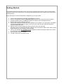
Getting Started
This chapter gives brief instructions how to set up the CR with an R/C receiver or servo motors. Not all
possible scenarios are covered here. It is highly recommended that the user read the entire manual prior
to using the CR.
Begin with step 6 once the CR has been configured by you or the vendor.
1.
2.
3.
4.
5.
6.
7.
8.
9.
Connect the USB cable to CR and to the USB port of your PC
Run the configuration software camremote.exe (file name may contain the version number)
Configure profile Set #1 (or additional profiles) according to your camera(s) and save
Remove CR from the USB port of the PC
Connect the USB cable to CR and to the USB port of your camera if you are going to use USB. If
the SERVO-FINGER method is used, connect the servo cable to CH2. Attach IR cable if IR
control is going to be used.
Manual control: Connect cables from R/C receiver to CH0, CH1 and CH2
Automatic control: Connect the pan servo cable to CH0, the tilt servo cable to CH1 and the power
supply (battery) to CH2 or Battery Terminal PWR
Turn on your camera (use playback mode if USB/PTP method is selected and be sure camera
is configured to PTP mode)
Wait until green LED lit constantly
The CR is now set up and ready to use
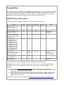
Compatibility
The CR is able to release the shutter with the SERVO-FINGER method on any camera but if the camera
has a built in remote function then there are additional options available for remote control. Currently, the
CR is able to handle several USB/PTP, USB/CHDK, USB/CA1, PORT/E3 and IR supported cameras.
Note USB/PTP and PORT/E3 are supported only in PRO and PRO-OSD versions.
USB/PTP (Only PRO version)
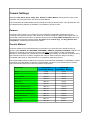
Controllable features of USB/PTP supported cameras are listed in following table:
Camera
Shoot
Zoom
Parameters
Extras
Canon PowerShot A-series:
A510, A520, A640
A60, A70, A75, A85, A95
Ok
Ok
Tv, Av, F, SQ
L, S
Canon PowerShot A310
Ok
NA
TBD
S
Canon PowerShot G-series:
G5, G6, G7, G91, G101
Ok
Ok
Tv, Av, F, SQ
L, S
Canon PowerShot S-series:
S50*, S60, S70, S80, S410*,
S500* S1 IS*, S2 IS*, S3 IS*
SX100*, SX110*
Ok
Ok
Tv, Av, F, SQ
L, S
TBD
TBD
TBD
TBD
Canon dSLR's:
300D, 350D, 400D, 450D,
500D*, 1D*, 5Dmk2, 7D*, 30D*,
40D*, 50D*, 1000D*
Ok
Zoom
Servo on
CH33
Tv, Av, F2, SQ*,
ISO*, WB*
Nikon Coolpix-series:
L4, L5-L18, P6000
OK
TBD
Nikon dSLR's:
D40, D60, all others
OK
NA
Canon IXUS series:
S110 (Digital IXUS v)*
S200 (Digital IXUS v2)*
S230 (Digital IXUS v3)*
S300 (Digital IXUS 300)*
S330 (Digital IXUS 330)*
S400 (Digital IXUS 400)*
S410 (Digital IXUS 430)*
S500 (Digital IXUS 500)*
SD100 (Digital IXUS II)*
SD110 (Digital IXUS IIs)*
Note
RAW mode is
unavailable
1
Manual focus drive is
available
3
CH3 is available only
on CR-2A version
2
Tv, Av, SQ, S to be
supported
* Not tested yet, may work but probably need improved firmware of the CAMremote
Descriptions: (Tv – Shutter speed, Av – Aperture, F – Focus unlock / lock, SQ – Size and quality, L –
Lens open/close control, S – Sleep mode, WB – White balance, NA – Not available, TBD – To be
defined)
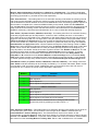
The following cameras have remote control disabled and don't work with CR in USB/PTP mode:
● Canon PowerShot A-series: A410, A420, A430, A450, A460, A530, A540, A550, A560, A570 IS,
A610, A630, A650 IS, A700, A710 IS, A720 IS
● Canon PowerShot S-series: S100, SD10, SD20, SD30, SD40, SD200, SD300, SD400, SD430,
SD450, SD500, SD550, SD600, SD630, SD700 IS, SD750, SD800 IS, SD850 IS, SD870 IS,
SD900, SD950 IS, SD1000
Check the full list from Canon web page, table PowerShot Features Supported by Compatible SDKs.
Note that Canon cameras have remote control limitations in USB/PTP mode and several camera features
are not available. For example startup time is slower compared to normal camera startup, there are
longer pauses between shots (more than 3 sec), there is a longer latency time between shutter release
command and shoot, there are no on-screen display texts/icons on LCD/Video-out (Powershots only), no
short post-view after shot (Powershots only), no manual focus (Powershots only, partial workaround is
available for focus).
USB/CHDK
The CHDK firmware add-on is a third-party software developed for Canon PowerShot cameras. Remote
controllable features are determined by CHDK firmware and user scripts but not by the CR. The CR
sends commands to camera via USB but CHDK scripts instruct the camera to perform the operations.
The following Canon cameras have remote control support added to CHDK firmware and work in
USB/CHDK remote mode:
●
●
●
●
Canon PowerShot A-Series: A450, A460, A470, A530, A540, A550, A560, A570IS, A590IS,
A610, A620, A630, A640, A650IS, A700, A710IS, A720IS, A2000IS
Canon PowerShot G-Series: G7, G9, G11
Canon PowerShot S-Series: S2IS, S3IS, S80, S5IS, SX100IS, SX110IS, SX10IS, SX20IS,
SX200IS
Canon IXUS Series: SD30, SD300 (IXUS40), SD400 (IXUS50), SD450 (IXUS55), SD500
(IXUS700), SD550 (IXUS750), SD600 (IXUS60), SD630 (IXUS65), SD700 (IXUS800IS), SD750
(IXUS75), SD800IS (IXUS850IS), SD850IS (IXUS950IS), SD900 (IXUS900Ti), SD1000
(IXUS70), SD770IS (IXUS85IS), SD790IS (IXUS90IS), SD870IS (IXUS860IS), SD890IS
(IXUS970IS), SD950IS (IXUS960IS), SD1100IS (IXUS80IS) SD780IS (IXUS100IS), SD880IS
(IXUS870IS), SD970IS (IXUS990IS), SD980IS (IXUS200IS), SD990IS (IXUS980IS)
Visit CHDK remote control web page to get latest information about supported cameras.
USB/CA1
The USB/CA1 protocol is developed by Ricoh and works with Ricoh GX100 and GX200 cameras only.
CA1 protocol offers 3 features: wakeup/power-down, focus and release shutter of the camera.
REMOTE PORT/E3 (Only PRO version)
The 3-pin remote control port is available on most of the Canon, Nikon and Pentax dSLR-type cameras
and has 2 controllable aspects: focus and release shutter of the camera. There is a fast continuous
shooting mode available as well.
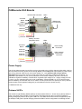
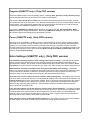
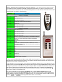
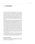
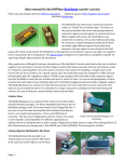
CAMremote-2/2A Boards
Infrared LED Connector
LED's
On-board
Button
Battery
(Regulator Input)
USB/Remote
Port Connector
Channel2
Channel1
Channel0
( ) Signal
(+) Power
(-) Ground
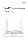
Battery Terminal
(Regulator Input)
On-board
Button
Channel3
Channel2
Channel1
Channel0
LED's
Video Overlay
Connector
USB / Infrared /
Remote Port
Connector
( ) Signal
(+) Power
(-) Ground
Power Supply
The CR can take its power from an R/C receiver connected to any of CR's channels (CH0-CH2, CH3*) or
can be powered from any power source through Battery terminal/Regulator Input (PWR) or power supply
pins of any channels. Note servos can accept usually 4.8...7.2V otherwise the servo(s) will be
damaged! Feed your power source to power pins of the any channels if voltage is less than 5..7V
(depends of specification of your servos) otherwise connect them to Battery Terminal. The CR has
onboard 5V regulator on Battery Terminal which regulates input voltage to 5V. Supply voltage pins are
(+) and (-) on any channels (CH0-CH2, CH3*) and Battery Terminal (PWR). So, if you connect power
source to Battery Terminal then there is no need to connect power source to power pins of any channel
because there will be regulated voltage 5V (or less depends of level of power source).
* CAMremote-2A only
Onboard LED's
The CR has 4 Light Emitting Diodes (LED's) on board where LED's #1...#3 are red (or yellow) and #4 is
green. The LED's show the state of the CR (green LED blinks quickly) when it performs operations.
During photography session when green LED is on, red LED's show code of active configuration profile.
At startup the CR goes to profile changing mode and LEDs of active configuration are blinking several
seconds. Indication codes of the configurations are shown in each configuration tab on software window
(see more info from chapter Configuration Software).
Channels
The CR has 3 or 4* bidirectional channels (CH0 – CH2, CH3*) which receive signals from an R/C receiver
(or any other electronics device including mechanical switches) in order to control the functionality of CR.
In automatic mode (Intervalometer or Panorama modes) the CR drives servo motors which can be
connected to CH0 and CH1. Channel CH2/CH3* is used for servo “finger” if needed (custom functionality
is also possible upon request).
* CAMremote-2A only
A USB Connector
USB Connector is used to connect CR to camera or to PC. Only the red LED #1 is lit (not blinking) when
CR is connected to a PC. Note USB connector is shared with IR connector on CAMremote-2A.
Alternative function of USB Connector is to control the REMOTE PORT/E3 using a special cable.
Infrared LED Connector
Connect the infrared LED cable plug to this connector and mount the infrared LED close to the camera's
IR sensor. If tiny IR plug is used, attach CAMremote-2 board onto camera so that IR LED points to
camera's IR sensor. Use tape or Velcro to attach it. Note IR connector is shared with USB connector on
CAMremote-2A.
On-board Button
An on-board button is used to select the desired profile. A short click of the button switches the CR to
profile selection mode and the onboard LED's start to blink to display the current profile identification.
Pressing the button again selects the next profile and the blinking LED's display the next profile
identification. If the button is not pressed for 3-4 seconds, the currently displayed profile will be selected.
Holding the button down for at least 4 seconds instructs the CR to command the camera to release the
shutter. This is useful to test the readiness of the camera for a photographic session. Note that CR is able
to send this command to camera only when the green LED is lit and the camera is turned on.
If the button is held down at power on, CR goes into bootloader mode (all LED's blink 8 times). The
bootloader mode is useful for recovery if a firmware upgrade has failed and CR is not able to
communicate with the PC.
Functions of the on-board button
Short click
Profile selection mode, on-board LED's start to
blink showing current profile identification
After short click, press the button until the LED's
show the desired profile
Select next profile
3-4 sec click and hold
Shutter release
Hold down at the power on moment
Bootloader mode, LED's blink 8 times
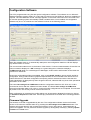
Configuration Software
The CR is programmable using PC with special configuration software. The software runs on Microsoft
Windows operating systems (2000, XP, Vista) and CR requires one free USB port. No driver installation is
required. The “New Hardware Found” message appears on the screen when CR is first connected to the
PC and the operating system automatically installs a suitable driver. Once installed, the configuration
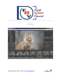
software may be run. A screenshot of the software is shown in the following picture.
When the software starts up, it automatically attempts to read configuration data from CR and displays
any retrieved items on screen.
The communication status bar is on the bottom of the window. If communication between CR and PC has
been successful it displays an “OK” message on a green background, otherwise it displays
“CAMremote I/O error” on a red background. Messages, serial number and firmware version fields are
next items on status bar.
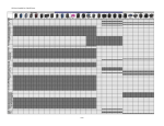
Seven user configurable profiles are available. Click on tabs Set#1...Set#7 to open a specific profile for
configuration. Every profile includes a graphical representation of CR's on-board LEDs. When CR's onboard LED's are lit in the same configuration the specific profile is selected and active. Note that this
profile identification is displayed only when the green LED is lit, otherwise CR may show other operational
information on the LED's.
The button Get settings from CAMremote reads the configuration data from CR. Click on it if CR is
connected to the PC after the software has been started. The button Save settings to CAMremote
stores all configuration data to CR. Click on it when all profile configurations are completed. This will store
all profiles in CR. The CR may now be removed from the PC.
When configuration is completed, the profile settings can be exported to Notepad for printing by clicking
on Profiles to Notepad from File menu. Printed copy would be like a reminder when choosing profiles in
the field.
Firmware Upgrade
The firmware of the CR is upgradeable by the user. The configuration software checks the firmware
version of CR when the software starts or by pressing the Get settings from CAMremote button. The
software will suggest that the user upgrade the firmware if it is an older version. Press Yes button to
perform an upgrade. You can perform a firmware upgrade (or downgrade) manually by selecting Update
Firmware from Tools menu.
Camera Settings
Settings for ISO Speed, Zoom, Image Size, Quality and White Balance are beyond the scope of this
document. They may be found in the camera's User Manual.
The CR software will enable/disable various settings according to selected items. This will helps the user
to understand which features are available or unavailable in specific modes.
Camera
Choose the exact model of your camera from the list because configuration parameters will vary
according to the selected camera. If the camera is not listed, choose the closest model. When use of a
camera with CHDK firmware add-on is desired, select from the list Any (CHDK Compatible). When use
of a simple servo-triggered camera choose Any (Uses servo control only). Use Any (Remote Port
Compatible) if camera with Remote Port are used.
Control Method
Choose a suitable control mode depending on the method you would like CR to interface with your
camera: using USB/PTP, IR, USB/CHDK, USB/CHDK+, USB/CA1, PORT/E3, PORT/E3A or Servo. This
list will vary according to the selected camera model. Note: when USB/PTP mode is selected CR
attempts to communicate with camera before it will be ready for shooting. The red LED #1 blinks at every
3sec intervals until CR is not able to negotiate with camera. Other modes are ready for shooting
immediately after power on because there is no negotiation phase with camera.
The CR generates pulses on USB when performing commands with USB/CHDK or USB/CHDK+ method.
Commands and pulse widths are shown in following table. Use them in your CHDK scripts to detect a
right command and instruct the camera to perform the operation.
Command
Pulse width
(USB/CHDK Method)
Pulse width
(USB/CHDK+ Method)
Shoot
10 ms
15 ms
Focus
65 ms
35 ms
Focus release
125 ms
55 ms
Zoom In
185 ms
75 ms
Zoom Out
255 ms
95 ms
Record video
325 ms
115 ms
Aperture increase (Av+)
385 ms
135 ms
Aperture decrease (Av-)
445 ms
155 ms
Shutter speed increase (Tv+)
505 ms
175 ms
Shutter speed decrease (Tv-)
565 ms
195 ms
Stop video record
625 ms
215 ms
Close lens
685 ms
415 ms
Power Off
745 ms
500 ms
Program (USB/PTP only) (Only PRO version)
Choose a suitable program from list. Setting options, including Auto, Aperture priority, Shutter priority
are not described here but may be found in the camera's User Manual.
The selection 'M' settings (Set on field) uses the camera's last settings which were manually set when
the camera dial was on the 'M' position. This allows the photographer to set the camera settings manually
before starting a new photography session with CR. Note that some cameras have C1 and C2 settings
but those are not accessible in USB/PTP mode and will be ignored.
The selection CAMremote settings allows the CR to use settings (Tv, Av, ISO, Quality/Size, White
Balance) set by the configuration software. Note when CAMremote settings is selected it will overwrite
the camera's last manual settings during photography session.
Focus (USB/PTP only) (Only PRO version)
Manual focus is not available in USB/PTP mode. A workaround is to point the camera toward an object,
command CR to perform focusing, and then lock the focus. Note that focusing always takes time before
shooting so try to keep the need for focusing minimal if fast shooting is important. Choose a suitable
focusing method from the list according to your requirements. Re-focusing can controlled manually by the
user during photography session when choosing Re-focus/lock controllable by Channel0. Read more
info from chapter Device Settings.
Extra Settings (USB/PTP only) (Only PRO version)
Full automatic shooting, ignores manual settings (lens opens at shoot) – This setting uses camera
feature to open lens and shoot picture using automatic shutter speed and aperture parameters and
ignoring all user settings. This is same command Windows sends to camera when user clicks on Take a
new picture link on the Camera Task window (XP, Vista only). After shooting the camera closes the lens.
Wait Channel0 or button event before open lens (green LED blinks when waiting) – This setting
waits for an external signal to be applied to Channel0 or waits for a button click before CR opens the lens.
This is useful when CR and the camera are powered up but there is need to protect the camera lens
during the setup of the photographing system (pole, helicopter/plane/kite lift-off etc).
Open lens only at shoot command (saves camera's battery during idle) – This setting opens the lens
only when shoot command is detected. The CR applies all settings to the camera which are defined in the
Camera Settings frame of the configuration software. Note: it requires a few seconds before the camera
opens the lens, starts up and is able to shoot a photo. This is useful when using long time photography
like astronomy, observing plant growth etc. After shooting the Camera closes the lens and thus the
camera goes into low power mode.
Lens and video off after 3 min idle until user involve (saves camera's battery) – This setting enables
the power save feature of the camera where after 3 minute idle time (no activity on input channels, button
or intervalometer) the camera closes the lens and goes into low power mode. Any interruption from
channels, button or intervalometer will wake the camera up. Note: it requires a few seconds before the
camera opens the lens, starts up and is able to shoot photos.
Keep camera's LCD on at shooting (disables video out) – This setting turns the LCD on and disables
the video signal on the video terminal. This is useful when testing the CR on the bench.
Device Settings
Device settings let the user choose the operating mode of the CR and configure several servo motor
related parameters.
Note that power off, zoom, focus, lens control and Tv/Av (shutter speed/aperture) control are available
only if your camera supports USB/PTP mode. For CHDK-compatible cameras, special CHDK scripts may
be used to control a variety of camera settings and features. More info about CHDK scripts will be
available on the CR web page.
Control Mode
Control Mode setting is used to set how CR is controllable: externally (Manual) by user (or any electronic
device) or internally (Automatic) by CR program. Channels CH0-CH2 of the CR are inputs when selected
value is Manual and CR is waiting commands via Channels. If selected value is Auto then channels of
the CR are outputs in most cases (are able to drive servos). There are several options how CR can be
controlled. More info about these options are listed below. Note not all options which are in list of
configuration software are not described here, several of them are under development.
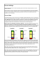
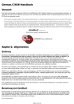
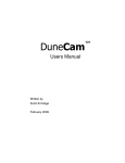
Manual: RC receiver (CH0=Shoot, CH1=Zoom, CH2=Alt) – This setting configures Channel0-2 (CH0CH2) to inputs and shoot, zoom and Tv/Av parameters are externally controllable by RC receiver.
Channels are sensible to pulse width coding signal. Most RC transmitters/receivers are generating pulse
width from 1 milliseconds (0%) to 2 milliseconds (100%) according to position of lever on control panel of
transmitter. Descriptions of lever positions and how CR interprets them are shown in following picture.
Lever positions
Channel0
Focus
Lever positions
Channel1
Lever positions
Channel2
100%
Shoot
100%
Zoom In
100%
Tv / Av
Change
Center
Idle
Center
Idle
Center
Idle
10%
0%
Lens off
0%
Zoom Out
0%
Profile
Change
CH2 is used to define functionality of CH0 and CH1. When CH2 is on idle position or left connected then
CH0 can be used to trigger the shutter, re-focus (optional, depending on Focus setting) and lens on/off
control and CH1 can be used to control the zoom of the camera. Move lever to 100% to shoot the photo.
Keep it on that position to repeat a shooting. Move it to center position to stop shooting. Camera closes
the lens if lever is set to minimum position (0%) and wakes up when moved away from minimum position.
Useful before completing the session to keep camera in safe condition (during descent of the
helicopter/kite/pole/blimp etc).
When CH2 is at maximum position (100%) then CH0 can be used to change shutter speed value and
CH1 can be used to change aperture value. Value increases by one step if lever is set to max position
and decreases when position is set to min. Center position is idle.
When CH2 is at minimum position (0%) then CH0 can be used to change configuration profile. Move CH0
lever to 0% and back to idle position to change profile to previous one. Move CH0 lever to 100% and
back to idle position to change profile to next one. Note: only same type of Control Mode profiles are
available, others are ignored. Use on-board button to change any profile.
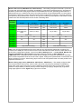
Manual: RC receiver (CH0=Execute, CH1=Function) – This setting configures Channel0-1 (CH0-CH1)
to inputs and CR functionality is manually controllable by general RC transmitter/receiver. Channels are
sensible to pulse width coding signal. Most RC transmitters/receivers are generating pulse width from 1
milliseconds (0%) to 2 milliseconds (100%) according to position of lever/potentiometer on control panel
of transmitter. Channel0 is used to execute function which is selected by Channel1. Use lever control for
CH0 (Execute) and potentiometer control for CH1 (function selection). Descriptions of transmitter controls
positions and how CR interprets them are shown in following table.
Channel1
Position
Channel0 Position
0..20%
21..39%
40..60%
61..80%
81..100%
Not used
-
Focus release
Idle
Auto focus
Shoot
0..10%
-
Focus release
Idle
Auto focus
Shoot
11..20%
Manual focus
drive down (2x
step)
Manual focus drive
down (1x step)
Idle
Manual focus drive Manual focus drive
up (1x step)
up (2x step)
Idle
Zoom in
21..30%
Zoom out
31..40%
Tv-
Tv-
Idle
Tv+
Tv+
41..50%
Av-
Av-
Idle
Av+
Av+
51..60%
-
-
Idle
-
-
61..70%
-
-
Idle
-
-
71..80%
Stop video recording
Idle
Start video recording
Note: User can test transmitter/receiver setup and see how CR interprets transmitter controls by PC.
Connect CR to USB port of the PC and connect control channels from radio receiver to CH0 and CH1 of
the CR. Run configuration software, choose from Device Settings frame -> Control Mode: Manual: RC
receiver (CH0=Execute, CH1=Function) and save settings by clicking on Save Settings to
CAMremote button. Messages (similar to table above) will appear to status bar (bottom line, third field)
which shows interpretation result of CH0 and CH1 signals. Change lever/potentiometer on transmitter and
follow messages on screen. Attach sticky paper close to lever and potentiometer and mark positions and
respective functions to it.
Manual: Rising edge sense (CH0=Shoot, CH1=Zoom+, CH2=Zoom-) – This setting configures CH0CH2 to inputs where shoot (CH0), zoom-in (CH1) and zoom-out (CH2) are externally controllable by
rising edge of the signal. Signal source can be whatever electronic device like microcontroller, motion
detector or simple switch (or button) which provides voltage to input pin(s). Simplest way to generate
rising edge signal is to short Signal and (+) pins for a moment.
Manual: By DuneCam (shutter/zoom/settings via CH0) – This setting configures CH0 to input and
shoot, zoom, lens open/close and Tv/Av settings are externally controllable by DuneCam or any other
programmable electronic system. CH0 is sensible to pulse width coding signal. Pulse width and its related
commands are shown in following table.
Pulse Width
(in microseconds)
Command
2000
Shoot
1900
Lens Close / Sleep
1800
Re-focus / Lock focus
1700
Zoom-In
1600
Zoom-Out
1500
Next Profile
1400
Previous Profile
1300
Shutter speed increase (Tv+)
1200
Shutter speed decrease (Tv-)
1100
Aperture increase (Av+)
1000
Aperture decrease (Av-)
Use scripts to perform Lens close/open, Zoom, Tv/Av and Profile change. Use Shoot command to wake
up the camera if it was commanded to sleep.
Manual: RC4 at CH0 (A=ZoomOut, B=ZoomIn, C=Shoot, D=Pause) – This setting configures CH0 to
input mode and shoot, zoom, pause settings are manually controllable by keyfob-sized radio
transmitter/receiver devices. Meaning of buttons A-D on transmitter can be customized upon request.
Manual: 4/8 Button Radio (CH0=Radio, CH1=Tilt, CH2=Pan) – This setting configures CH0 to accept
commands from radio module and manually control tilt and pan servos. Tilt servo is connected to CH1,
and a pan servo is connected to CH2. Functional descriptions of 4- and 8-button transmitters and how CR
interprets them are shown in following table.
Buttons
Function
4-Button Transmitter
1
Shoot
2
Drive tilt servo up
3
Drive tilt servo down
4
Combined function with other button
4+1
Close lens
4+2
Drive pan servo right
4+3
Drive pan servo left
8-Button Transmitter
1
Drive tilt servo up
2
Drive tilt servo down
3
Drive pan servo right
4
Drive pan servo left
5
Zoom in + (roll or zoom) servo up on IR/CH3 channel*
6
Zoom out + (roll or zoom) servo down on IR/CH3
channel*
7
Shoot
8
Combined or Alternate function: Hold down 6 sec to
change profile and then choose new profile by pressing
on profile number 1-7
8+1
Tv+
8+2
Tv-
8+3
Av+
8+4
Av-
8+5
Power off
8+6
Close lens
8+7
Start/stop video recording
* Zoom can be controlled electronically through USB if camera support it and can be controlled also by
external servo motor through IR port (CR2) or CH3 (CR2A) as well. IR/CH3 channels can drive roll servo
instead of zoom if zoom is not planned to use.
Tilt and Roll/Zoom servo parameters can be defined in Tilt Servo Position frame. Value #1 defines initial
position of the servo and value #2 defines step size of the movement. Value Apply Time is used to define
driving time (continuous or limited time only). For example if #1 is 0° and #2 is 10° then servo makes ±10°
step at every tilt/zoom/roll command (direction is depending of #2 sign). If values #1 and #2 are None
then CR is using internal predefined values. User can test these values on real servos by pressing |>
button. Servo must be connected to CH1.
Pan servo parameters can be defined in Pan Servo frame. Value Starting Position defines initial
position of the servo and value Next ±Position defines step size of the movement. Value Apply Time is
used to define driving time (continuous or limited time only). You can test these values on real servos by
pressing |> CH0 or |> CH2 buttons (depends where servo is connected).
Manual: Switch (CH0=Shoot, CH1=Focus+, CH2=Focus-, CH3=Record) – This setting is dedicated
mostly for DSLR cameras where shooting, manual focus drive and video record/stop can be controlled by
connecting (S) terminal to (-) terminal of CH0-CH3 respectively.
Auto: Intervalometer – This setting sets CR to an automatic shooting mode where the shooting interval
and count are user selectable. Choose the maximum number of shots desired from the Total Shots list
and the desired time interval between shots from the Interval list. Note: the shooting operation requires a
few seconds to complete which causes an additional delay to the interval. Select the value Minimum
from the Interval list if the fastest possible shooting is required. The camera closes the lens and goes into
sleep mode when the shooting counter reaches the maximum value selected from the Total Shots list
(USB/PTP mode only). Hold down the onboard button for 3-4 sec to restart the shooting sequence.
Auto: HoVer ('V'-pattern motion, CH0=Pan, CH1=Tilt) – This setting sets CR to an automatic shooting
mode with programmable pan and tilt positions. A normal or 360° modified pan servo is connected to
CH0, and a tilt servo is connected to CH1. Depending on the camera being used, the user can choose to
trigger the camera using USB, IR, or a finger-servo. The pan and tilt positions are programmable via the
Tilt Servo Positions and Pan Servo items. The CR uses the following sequence when controlling the
servos: tilt to position #1, position #2, position #3, position #4, position #5, then pan using user-selected
Next ±Position and Apply Time values. CR then repeats the sequence until reaching number of Total
Steps value. After reaching this value the CR drives servo to Starting Position (if this value is other than
SR360° which means 360° modified servo is used) and starts panning sequence at the beginning. At
every tilt position, the camera shoots the number of photos chosen in the Number of Shots list. The CR
completes shooting when number of Total Shots (in Intervalometer frame) is reached. To prevent
camera shake due to servo movements, select suitable time values from the lists Delay Before and
Delay After. If IR is selected from the Control Method in Camera Settings frame, use suitable Delay
After value to allow camera to complete the shoot command before next step (usually 3-7 sec depends
on shutter speed and image size). Please read more from Recommended pan and tilt settings below.
Auto/Manual: HoVer ('V'-pattern motion, CH0=Radio, CH1=Tilt, CH2=Pan) – This setting is same as
Auto: HoVer mode but start/stop can be manually controlled by 4- or 8-button transmitter. Radio module
is connected to CH0, a normal or a 360° modified pan servo is connected to CH2, and a tilt servo is
connected to CH1. Features of manual control are listed in table below.
Buttons
Function
4-Button Transmitter
1
Start sequence
2
Pause sequence
3
Pause sequence and power off the camera
8-Button Transmitter
1
Start sequence
2
Pause sequence
5
Pause sequence and power off the camera
6
Pause sequence and close lens of the camera
8
Alternate function: Hold down 6 sec to change profile and then
choose new profile by pressing on profile number 1-7
Auto: Panorama (CH0=Pan) – This setting sets CR to automatic shooting mode where CH0 is driver for
a horizontal (Pan) servo motor. The CH2 will be a servo-finger driver if Servo is selected from the
Control Method in Camera Settings frame. The desired amount of pan servo rotation is user
programmable via the Pan Servo list. After each servo rotation, the camera shoots the number of photos
selected in the Number of Shots list. To prevent camera shake due to servo movements, select suitable
time values from the lists Delay Before and Delay After. Either a 360° modified servo or a Parallax
(Futaba) Continuous Rotation servo should be used. If IR is selected from the Control Method in
Camera Settings frame, use suitable Delay After value to allow camera to complete the shoot command
before next step (usually 3-7 sec depends on shutter speed and image size).
Recommended pan and tilt settings
Use Defaults button to get predefined values of servo settings.
Tilt Servo Positions is used to select desired tilt. There are 5 positions available. Choose None if you
want to skip any position(s). The listed values are in microseconds or degrees (selectable from menu:
Tools->Servo Units). A value of approximately 1 ms will move the tilt servo to one extreme (either horizon
or straight down) and a value of approximately 2 ms will move the servo to the other extreme. A value of
1.5 ms (0°) will move the servo to a center position . These values are rules of thumb, and most servos
are able to rotate more than 180°, so you can experiment with larger or smaller values too. User can test
these values on real servos by pressing |> button. Servo must be connected to CH1.
Pan Servo parameters are used to control a Pan servo position. Normal or a 360° modified servo or a
Parallax (Futaba) Continuous Rotation servo should be used. When a 360° modified servo is used, set
Starting Position value to SR360°. Use the Next ±Position parameter to set the direction of the rotation.
Usually 1.5 ms (0°) is the center point but this may vary depending of the servo. The servo rotor turns left
if the value selected is less than the center value and turns right if the value selected is greater than the
center value. The servo makes a smaller rotation if the value selected is closer to center point. Use the
Apply Time setting to determine how long the servo motor is driving its rotor (only 360°-modified servos).
For example the servo rotates about 45° (depends of servo) if the Next ±Position is set to 1.4 ms (-9°)
and the Apply Time is 400ms. User can test these values on real servos by pressing |> CH0 or |> CH2
buttons (depends where servo is connected).
Pan and Tilt servos will be driven continuously by CR if Apply Time value is Always. This is
recommended setting if camera is too heavy and keeping of servo position fixed is impossible during idle
time. Note continuous driving consumes more current from power source than short time driving.
You may need to experiment with different values to find a suitable combination. Note: You have to
power up any of the channel or PWR terminal from external power supply or battery in order to test
servos. First connect CR to USB port of the PC and after that power up the CR from any channel or PWR
terminal.
Support
CAMremote is continually improving as a result of the feedback and suggestions of users. Ideas for
improvements and requests for new feature are welcome and greatly appreciated. Bug reports will be
investigated and corrected as soon as possible. To report a problem or request a new feature, please
contact us by email at [email protected] or through our web page http://vp-systems.eu -> Contact.
Visit CAMremote’s support page to get updated software and documentation.
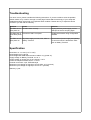
Troubleshooting
If an error occurs, please consider the following instructions. If you are unable to solve the problem,
please contact us by e-mail or through our web page. Please attach screencopy of your setup and
detailed description which help us to replicate same condition. Please don’t try to repair the device
yourself or you will void the warranty.
Problem
Cause
Solution
All LED's are on
after power on
CR didn't start correctly
Unplug CR from power supply or from
USB port of the PC and plug again
All LED's blink 8 Firmware of CR is corrupted
times after power
on
Update the firmware using configuration
software
All LED's are off
after power on
Check wires of power supply and polarity
of connector which is attached to CH0CH2 or Battery Terminal
No power supply on CH0, CH1, CH2 or
Battery Terminal.
Specification
Board size: 31 x 21 mm (1.22” x 0.83”)
Board weight: 3g (0.106 oz)
Board weight with USB and three servo cables: 18 g (0.635 oz)
Supply voltage on Battery Terminal: 3.7-12 V
Supply voltage on power pins of any channel: 3-16 V
Power consumption without servos: 1-15 mA
Channel connectors: 3-pin JR/Futaba style
Maximum input voltage on Signal pin of CH0-CH2: 10 V (survival)
Maximum input voltage on Signal pin of CH3: 5 V (survival)
Warranty 1 year.