1
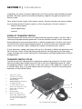
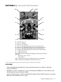
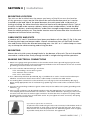
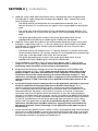
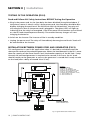
Transfer
Switch
30 Amps
STS-30
Owner's
Manual
Please read this
manual before
operating your
transfer switch
Owner's Manual | Index
Section 1
Introduction........................................................................... 3
Section 2
General information .............................................................. 5
Section 3
Installation ........................................................................... 6
Section 4
Troubleshooting .................................................................. 12
Section 5
Specifications ...................................................................... 14
Section 6
Warranty .......................................................................... 15
DETAILED PRODUCT INFORMATION
For a complete user manual including specifications,
application notes, installation instructions, trouble shooting
and more, please visit the web page for this product on
samlexamerica.com. Product page can be found using the
“search by model” field.
2 | SAMLEX AMERICA INC.
Section 1 | Introduction
Function of a Transfer Switch
In case of failure of the main AC power source like the electric utility power, it is desirable to switch the critical AC loads to a standby / back up AC power source like a generator or an inverter. The switching action should ensure that only one AC power source is
connected to the AC loads at any one time and that the electric utility power and the
generator / inverter output power are never connected in parallel but remain isolated
The electrical loads cannot be connected in parallel with the generator/ inverter and
electric utility power at the same time. This will cause the following damage and safety
hazards:
- The electric utility line voltage is normally "stepped down" by a transformer before
entering the home / RV park / campground. The transformer will work in reverse
when voltage is sent through it in the opposite direction and will "step up" the
voltage fed back into it. If the electric utility power is interrupted (say the feeder
section upstream is switched off by workers for repairs), the generator / inverter
will feed voltage back into the electric utility power lines, this voltage will be
stepped up by the transformer and will electrocute the workers that come into
contact with the utility lines.
- If the electric utility power and the generator / inverter are alive at the same time,
the electric utility power will be fed back into the generator/ inverter and the generator / inverter will get damaged. There is also a potential of fire!
Application of Transfer Switch in Homes
By installing a transfer switch at your breaker box and connecting a generator/inverter
to the transfer switch, you can run selected circuits for appliances such as a furnace, well
pump, sump pump, refrigerator, television, computer, printer or lighting circuit during a
power outage, depending on the capacity of your generator / inverter.
Application of Transfer Switch in
Recreational Vehicles (RVs)
RVs have both a 12 VDC house or domestic system and a 120 VAC system. The DC system
commonly provides power for area lighting, stereo, water pumping and other loads
requiring relatively small amounts of power. The 120 VAC system powers larger loads
like microwave ovens, hot water heaters, washer /dryer, coffee machines, hair dryers,
space heaters, heating and air-conditioning (HVAC) and convenience outlets that supply
power to audio, video and entertainment systems. The domestic refrigerator is commonly supplied by both the 12 VDC and the 120 VAC system and sometimes alternatively by
propane.
Inverters are also used to provide AC power for dry camping where AC shore power
is not available or in cases where gensets are not permitted due to noise restrictions.
Typically, the inverter only supplies AC devices that are the highest priority such as
microwave, entertainment and convenience outlets. It is not practical to run loads like
hot water heaters and HVAC systems from inverters that are ultimately powered from
batteries.
SAMLEX AMERICA INC. | 3
SECTION 1 | Introduction
Frequently, the total AC power requirement of all the system loads exceeds the campground / RV park’s power inlet and consequently, requires the genset to power the
entire system.
Thus, there may be 3 types of AC power sources. Transfer switches are used to configure switching of the AC power sources so that the priority of the AC sources is:
-Electric utility power
- Genset (generator)
-Inverter
Sizing of Transfer Switch
Determining which circuits you will require during a power outage is the first step in
selecting the proper backup generator / inverter and the transfer switch. Since most
home appliances operate intermittently, a 3000 watt generator / inverter and a 30 A
Transfer Switch can provide adequate power to circuits for the most common appliances, such as furnace, lights, refrigerator, freezer, microwave oven, and TV.
If your home has a deep well pump with up to 1 HP motor, a 5000 watt generator and
50 A Transfer Switch will be required to provide the starting capacity for the pump.
Larger wattage units can be selected for simultaneous starting and operation of multiple appliances.
Transfer Switch STS-30
Transfer Switch STS is designed for single phase operating voltage of 120 VAC, 60 Hz
and can handle input/ output current of up to 30 A or an Apparent Power of 3600
VA (Apparent Power = Volts X Amps. In this case: 120 V X 30 = 3600 VA). It consists of
a Transfer Relay (Fig. 2, R1) and a Relay Control PCB (Fig. 2, PCB1) for controlling the
operation of the Transfer Relay.
1.
15A power cord for
connection to inverter.
2.
15A, NEMA5-15P North
American plug
3.
NEMA-20R Duplex receptacle
for battery charger
4.
¾” cable clamp for shore
power cord / generator cord
5.
Cable clamp for inverter
power cord
6.
Grounding lug
7.
Spare knockouts for ¾”
cable clamp. Additional ¾”
& 1” knockouts are provided
on the two other sides (not
shown).
4
2
3
7
6
1
5
Fig. 1 External view and layout
4 | SAMLEX AMERICA INC.
Section 2 | General Information
SW1
LED1
PCB1
T5
T6
T3
T4
R1
T7
T1
-----------
--Fig. 2
T8
T2
R1 - Transfer relay coil
T1 - Line "L", Common
T2 - Neutral "N", Common
T3 - Line "L1", NO (Normally open contact of transfer relay)
T4 - Neutral "N1", NO (Normally open contact of transfer relay)
T5 - Line "L2", NC (Normally closed contact of transfer relay)
T6 - Neutral "N2", NC (Normally closed contact of transfer relay)
T7 - input for relay coil
T8 + input for relay coil
SW1 - DIP Switch for enabling / disabling time delay for transfer to
generator
-- Off: Delay of 20 - 25 sec.
-- On: No delay
LED1 - Green LED - On when transfer relay coil R1 is energized
PCB1 - Printed Circuit Board for transfer relay control
Internal layout of contacts of the transfer relay and the PCB for relay control
Features
- Can be configured for generator / power cord connection or inverter / alternate
source connection
- Multiple ¾” and 1” knockouts (7, Fig. 1) have been provided on all the sides for ease
of routing the input and output cables
- Consists of heavy duty 110 VDC, Double Pole Double Throw (DPDT) relay for switching
both the Line and Neutral. (R1, Fig 2)
SAMLEX AMERICA INC. | 5
SECTION 3 | Installation
- Internal DIP Switch ( SW1, Fig 2) for enabling or disabling delayed transfer
to generator
- Internal LED (LED1, Fig 2) for indicating energized condition of the transfer relay coil
(R1, Fig 2) and for diagnostics
Operation of the Transfer Relay (Please see Fig 2)
Relay R1 is a Double Pole Double Throw (DPDT) relay and is used to switch power from
one source to the other. The relay coil is energized as soon as 110 VDC is fed to terminals
T7 and T8. When the relay coil is de-energized, the common contact terminals T1 and
T2 are connected to the Normally Closed (NC) contact terminals T5 and T6 respectively.
When the relay coil is energized, the common contact terminals T1 and T2 switch over
to the Normally Open (NO) contact terminals T4 and T5.
The relay coil operates at 110 VDC. This voltage is generated and controlled by the circuitry located on PCB1. 120 VAC is tapped from contact terminals T3 and T4, is rectified
and made available to the relay coil terminals T7 and T8 through a time delay circuit.
DIP Switch SW1 located on the PCB1 is used to enable or disable the time delay circuit.
When the Time Delay Circuit is enabled (SW1 in OFF position (1). This is the factory
default preset position), 110 VDC control signal for energizing the relay coil is delayed
by around 20 to 25 sec from the time 120 VAC is made available at the NO contact terminals T3 and T4. When the time delay circuit is disabled (DIP Switch in ON position), the
110 VDC control signal for energizing the relay coil is made available to terminals T7 and
T8 as soon as 120 VAC is made available at the NO terminals T3 and T4.
As soon as the 110 VDC control signal is fed to the relay coil to terminals T7 and T8, the
green LED 1 lights up indicating that the relay coil has energized.
The delay of around 20 to 25 sec is required when the AC load is transferred to the generator. The generator should never be started on load. Also, the generator takes around
20 to 25 sec to stabilize in voltage and frequency.
Safety Instructions
Connections for stand by / backup power to a building / RV system using the transfer
switch must be made by a qualified electrician and must comply with all applicable laws
and electrical codes.
-- Before starting installation, disconnect all live sources or power. Make sure that the
generator is off, the external shore power cord is unplugged, and the inverter, if
any, is shut off.
--
The unit is not weather proof and should be mounted in a cool, dry and protected
environment.
--
To prevent exposure to foreign contaminants, do not mount the transfer switch
in an engine compartment, under kitchen sink drains or water pipes, within the
battery compartment, or in any compartment designed for storage of flammable
liquids such as gasoline.
6 | SAMLEX AMERICA INC.
SECTION 3 | Installation
Mounting location
The unit can be installed near the power cord entry of the RV or near the location
of the generator output on the line side of the main distribution panel, or it can be
installed on the load side of the panel between the main panel and a sub panel, allowing switching for either the entire electrical load or only designated circuits. Typical
locations include under counter cabinets, below closet compartments, inside the bed
pedestal or cabinets, overhead cabinets, under-floor storage compartments accessed
from the vehicle exterior, etc. The chosen location must be accessible after installation is
complete to facilitate future servicing.
Cable entry and exits
A number of ¾” and 1” knockouts have been provided on all the sides (7, Fig 2) for ease
of routing the input and output cables. Choose a knockout that will facilitate installation and service within the selected mounting area. Use 3/4” or 1” cable clamps as necessary to clamp the cables entering and exiting the box.
Mounting
Mount the unit with screws through holes in the bottom of the unit. The unit should be
screwed to a solid surface firmly enough to hold its weight during vehicle operation.
Making electrical connections
1.Attach an 8 gauge earth ground wire to the transfer switch chassis ground lug (6, Fig 2). 4 studs
with serrated lock washers and nuts have been provided on the inner bottom of the case to make
grounding connections from the inner side .
2.The color code for 120 VAC wiring is as follows:
• The "Grounding" wire is bare or green.
• The "Neutral" wire is white.
• The "Line" wire is black.
3. A ¾” cable clamp has been provided (4, Fig. 1). Additional ¾” and 1” knockouts have been provided for convenience. Please ensure that a cable clamp is used for the cable entries.
4. For making firm connections to the terminals (T1 to T6, Fig 2) of the Transfer Relay (R1, Fig 2),
please crimp appropriate size of insulated ring / spade lugs on the ends of the conductors of the
cables.
5.Connect the grounding conductors (green / bare wire) of the cables to the spare grounding studs
marked ( )
6.Two or more conductors can be spliced together using the appropriate size of twist-on type of
cone shaped, plastic insulated wire nut connector - also called "Marrette" (See Fig. 3). The connector twists over the wires to make a tight connection around the wires. A square-cut spring inside
provides tension on the wires to hold them secure. As you tighten the wire connector, the spring
draws tighter around the wires.
Fig.3. Twist-on type of wire nut connector.
To splice the wire leads using the wire nut connector, hold the bare ends of
the wires parallel to each other so that the wire tips are even, then secure
with the wire nut. Use the proper size nut. Manually tighten nuts as tightly
as possible. Verify that all connections are tightened.
SAMLEX AMERICA INC. | 7
SECTION 3 | Installation
Installation Configurations
Preset Configuration - General
This Transfer Switch has been especially pre-wired for ease of connections for setting up
a backup power / UPS (Un-interruptible Power Supply) system comprising of an Inverter,
a battery charger and batteries. A backup power system / UPS can be used in on-grid,
off-grid and RV applications. General overview and features for the pre-wired configuration are given below:
- The primary AC power will be the electric utility power (also called the Shore Power Cord or “Cord” in RVs) or a generator. This is connected to the Normally Open
Contacts T3 and T4. A NEMA-20R Duplex Receptacle (3, Fig. 1) has been provided
on the side of the unit for ease of connecting the NEMA5-15P or NEMA5-20P plug
of a battery charger
- The back-up power will be provided from an inverter. A 15 A power cord (1, Fig 1)
with a 15 A, NEMA5-15P plug (2, Fig. 1) has been provided. This allows very convenient connection to the 15 A, NEMA5-15R receptacle provided on the inverter.
The maximum power of the back up inverter should be less than 1800 VA as the
maximum capacity of the cord provided for the inverter connection is only 15 A.
Preset Configuration - Detailed Information (Please see Fig. 1, 2 and 4)
NEMA5-20R
DUPLEX
RECEPTACLE
ON
LED1
TERMINALS:
T1
T2
T3
T4
T5
T6
T7
T8
SW1
–
BATTERY
+ CHARGER
T5
T6
T7
T5
T1
T2
T4
T3
20A
FUSE
BATTERY SIDE FUSE
FOR CHARGER
+
–
BATTERY
BATTERY
SIDE FUSE
FOR
INVERTER
LINE “L”, COMMON
NEUTRAL “N”, COMMON
LINE “L1”, NO (NORMALLY OPEN)
NEUTRAL “N1”, NO (NORMALLY OPEN)
LINE “L2”, NC (NORMALLY CLOSED)
NEUTRAL “N2”, NC (NORMALLY CLOSED)
– INPUT FOR RELAY COIL
+ INPUT FOR RELAY COIL
INPUT FROM
ELECTRIC UTILITY / SHORE
POWER CORD OR GENERATOR
TO NORMALLY OPEN (NO)
CONTACT TERMINALS T3,T4
INVERTER
+
–
+
–
INPUT FROM INVERTER
TO NORMALLY CLOSED (NC)
CONTACT TERMINALS T5,T6
OUTPUT TO
AC BREAKER
PANEL
MAIN
30
1 2 3 4 5
BRANCH CIRCUITS
30 A MAIN
BREAKER PANEL
Fig.4. 30 A System for alternate source / inverter.
FIG 4 30 A SYSTEM FOR ALTERNATE SOURCE / INVERTER
8 | SAMLEX AMERICA INC.
EXISITING ON-BOARD
CONVERTER
DISCONNECT
THE CONVERTER
+
CONVERTER
TO BATTERY
–
SECTION 3 | Installation
a. Feed the 3 core cable from the electric utility / shore power cord / the generator
through the ¾” cable clamp that has been provided (4, Fig1). Connect the three
cores as follows (Fig 4):
--
The black core to the black piece of wire connected to the NO, Line “L1”
contact terminal T3. Use the twist-on type of wire nut provided for splicing the
ends.
--
The white core to the white piece of wire connected to the NO, Neutral “N1”
contact terminal T4. Use the twist-on type of wire nut provided for splicing the
ends.
--
The green grounding core to one of the spare grounding studs. Use an
appropriate insulated ring or spade lug for making this connection
b. Feed the 3 core cable for output to the main breaker panel by using a convenient
knockout / cable clamp (3/4” or 1”) for the cable entry. Cable clamp has not been
provided for this connection and has to be provided by the user. Connect the 3
cores as follows (Fig 4):
--
The black core to the common Line “L” contact terminal T1 and the white core
to the common Neutral “N” contact terminal T2. Use appropriate insulated ring
/ fork lugs at the bare end of the wires for firm contact.
--
The green grounding core to one of the spare grounding studs. Use an
appropriate ring or spade lug for making this connection
c. Plug the NEMA5-15 plug (2, Fig 1) of the inverter power cord (1, Fig 1) to the
output of the inverter (Fig 4). Please ensure that the inverter is switched off and
the battery input connection to the inverter is disconnected.
d. Plug the external battery charger to one of the receptacles of the NEMA-20R
Duplex receptacle (3, Fig 1; Fig 4). Please ensure that the AC input current of the
battery charger is less than 16A continuous as the receptacle is internally fused
at 20A max. In case the current drawn by the external battery charger is > 16A
continuous, the charger should be wired to a separate circuit connected to the NO
contact terminals T3 and T4 through a fuse applicable to the input current of the
charger.
e. In case the Transfer Switch is being used in an RV application, the built-in converter
of the RV should be disconnected from the AC Breaker Panel (Fig 4). This is
necessary because when the electric utility / shore power cord / the generator
fails / is removed, the panel will be fed by the inverter and if the converter is not
disconnected from the panel, it will result in a battery to inverter to converter
to battery loop that will quickly drain the batteries. In case the external battery
charger is not being used, the converter may be re-wired to the NEMA5-20R Duplex
receptacle (3. Fig 1). As these receptacles are connected to the NO contact terminals
T3 and T4, the converter will always be powered from the electric utility / shore
power cord / the generator. In case the current drawn by the converter is > 16A
continuous, the converter should be wired to a separate circuit connected to the
NO contact terminals T3 and T4 through a fuse applicable to the input current of
the converter.
f. In case the primary power source is electric utility / shore power cord, the time delay
of 20 sec has to be disabled by setting the internal DIP Switch SW1 (Figs 2, 4) to ON
position. In case the primary source is generator, the internal DIP Switch SW1 (Fig 2,
4) should be retained in the preset off condition (1) .
SAMLEX AMERICA INC. | 9
SECTION 3 | Installation
Testing of the operation (Fig 4)
Read and Follow All Safety Instructions Before Testing the Operation
a.Plug in the power cord. As the time delay has been disabled (As explained above, if
the primary source is electric utility / shore power cord, the time delay should be disabled by changing the position of the DIP Switch SW1 to ON position), the relay coil
will energize as soon as the power cord is plugged in. The green LED1 will light up
indicating that the relay has energized. If the main panel circuit breakers are switched
on, the RV loads should operate normally. The external battery charger will start
charging the batteries.
b.Switch on the inverter. The inverter will be in standby condition.
c.Unplug the power cord. The relay will immediately de-energize and the AC loads will
be transferred to the inverter.
Installation between Power Cord and Generator (Fig 5)
This configuration is used in RV application when it is desired to switch between the
shore power cord and the onboard generator. When the load demand in the RV is more
than the capacity of the Shore Power Cord / the breaker capacity of the RV Park / Camp
Ground, the on-board generator is required to be started. In this case, the AC loads
should transfer to the generator as soon as the generator is started and is ready to take
on the load (after a delay of around 20 to 25 sec).
ON
LED1
PCB1
T5
T6
T3
20 A
FUSE
TERMINALS:
T1
T2
T3
T4
T5
T6
T7
T8
SW1
LINE “L”, COMMON
NEUTRAL “N”, COMMON
LINE “L1”, NO (NORMALLY OPEN)
NEUTRAL “N1”, NO (NORMALLY OPEN)
LINE “L2”, NC (NORMALLY CLOSED)
NEUTRAL “N2”, NC (NORMALLY CLOSED)
– INPUT FOR RELAY COIL
+ INPUT FOR RELAY COIL
T4
T7
T8
T1
T2
INPUT FROM SHORE POWER CORD
TO NORMALLY CLOSED (NC)
CONTACT TERMINALS T5,T6
OUTPUT TO
AC BREAKER
PANEL
INPUT FROM GENERATOR
TO NORMALLY OPEN (NO)
CONTACT TERMINALS T3,T4
MAIN
30
1 2 3 4 5
BRANCH CIRCUITS
30 A MAIN
BREAKER PANEL
10 | SAMLEX AMERICA INC.
Fig. 5 Typical Generator / Power Cord
SECTION 3 | Installation
a.Connect the Shore Power Cord leads to the Normally Closed (NC) contacts T-5 and T-6
of the Transfer Relay. The pre-wired 15 A cord (1, Fig1) and NEMA5-15 plug (2, Fig 1)
can be used for 15 A service (If it is required to be connected to a 30 A service, this
cord should be replaced with a 30 A cord).
b.Connect the generator leads to the Normally Open (NO) contacts T3 and T4 of the
Transfer Relay .If convenient, use the knockout and the ¾” cable clamp provided –
marked “Shore” (4, Fig 1). Otherwise, use any other convenient knockout with corresponding cable clamp.
c Connect the Breaker Panel to the Common Contacts T1 and T2 of the Transfer Relay.
d.The time delay circuit should be energized. The DIP switch SW1 (Fig 2) should be in
the “off ” position (marked “1”).
Testing of the operation (Fig 5)
Read and Follow All Safety Instructions Before Testing the Operation
a.Plug in the power cord. If the main panel circuit breakers are switched on, the RV load
should operate normally. Unplug the power cord.
b.Start the generator. There is a pre-programmed 20 to 25 second delay in the transfer
switch. The delay is designed to allow the generator a brief warm-up period. When
the delay completes its cycle the switch should engage and the RV load should operate normally. An audible click should sound as the switch engages.
c.Shut down the generator. As the generator winds down the switch should disengage
without chatter or cycling. An audible click should sound as the switch disengages.
d.Plug in the power cord. Start the generator. After the pre-programmed delay, the
switch should transfer power automatically from the power cord to the generator. Listen for the audible click as the switch transfers. Green LED1 will be lighted indicating
that the relay has energized. Shut down the generator and unplug the power cord.
SAMLEX AMERICA INC. | 11
SECTION 4 | Troubleshooting
Low voltage
Low voltage is harmful to most appliances. Relay based transfer switches are also affected by low voltage; if the voltage level drops lower than the holding voltage of the
coil, the relay contacts will “chatter”. Sustained contact chattering may cause damage.
General low voltage
Low voltage can be caused by low voltage conditions such as in an RV park with
inadequate wiring for crowded camper conditions where everyone’s electricity suffers
(brownout). In this case, a voltmeter will be helpful and will show a low voltage reading from the park receptacle, even before the RV is plugged in. When you experience
general low voltage conditions, remember, that brownouts can be harmful to most
appliances. A better alternative might be to utilize the generator until park voltage
conditions improve.
Localized low voltage
Low voltage conditions can be caused by specific situations such as an additional cord
which is too long and too small for the load. Do not attempt to extend the RV power
cord by using a 16 gauge 100 foot extension cord, or any cord not rated for an RV-size
load. A localized low voltage condition will result when a load is turned on which is
larger than that which the cord is designed for. As soon as the RV tries to draw more
current than the amount for which the cord is rated, the voltage will fall within the
length of the cord, and the RV will experience low voltage. This is especially noticeable
during inrush current situations such as an air conditioner start-up.
Time Delay for Generator
As already explained earlier, once a generator is started, it should not be loaded immediately. The time delay is necessary during generator start-up so that the generator
does not have to start under load; the delay is not necessary for electric utility power /
Shore Power Cord or inverter. Therefore, in transfer switch operation where the Transfer
Switch is controlling an AC source other than a generator, the time delay should be
disabled and DIP Switch SW1 should be set to (ON) position. This will allow instantaneous switching.
Another time for disabling the delay is during diagnostic and troubleshooting efforts;
if disabling the delay causes the switch to work when it otherwise won’t, then the
time delay circuit has malfunctioned and the control board PCB1 will be required to be
replaced. To disable the time delay, the DIP Switch SW1 should be set to (ON) position.
When time delay is disabled, the transfer will be instantaneous.
12 | SAMLEX AMERICA INC.
SECTION 4 | Troubleshooting
Failed time delay circuit
It is possible for a voltage spike, etc. to cause the time delay module to fail: if this happens the switch will no longer transfer. If the AC input to the control board PCB1 is
available and the LED does not light after 20 to 25 seconds, the time delay function in
the module has failed, and the module will be required to be replaced. To verify this, try
setting the time delay switch on the PCB1 to disabled position (ON); the switch should
transfer with no delay. Note that this position will allow emergency operation until the
module can be replaced; however there will not be a 20 - 25 second delay for generator
start-up. All repairs should begin by unplugging and replacing PCB1 for relay control
first. However, if the LED1 is on and the switch is not working, then PCB1 for relay control is functioning properly and the switch has other problems, such as a failed relay and
the entire switch will be required to be replaced.
SAMLEX AMERICA INC. | 13
SECTION 5 | Specifications
ModelSTS-30
Input / output voltage
120 VAC, 60 Hz
Input / output current
30A*
Battery charger receptacle
NEMA5-20R Duplex Receptacle
20A max.
16A continuous
Fused at 20A
Knockoutsfor 1” and ¾”
Maximum operating time of the relay
25 msec
Delay time for generator warm up
20 sec + / - 5 sec
Enabling / disabling of delay time
Yes. With DIP switch SW1
• Delay enabled: OFF (1)
(This is the default factory
setting)
• Delay disabled: ON
Operating temperature0 - 40o C / 32o F to 104o F
Dimensions W X D X H (with max protrusions)
in
8.4 x 9.0 x 3.2
mm
213.4 x 228.6 x 81.3
Weightlbs
4.4
kgs
2.0
!
*A 15A cord with NEMA5-15P plug has been provided for convenience
of connection to an inverter / generator with continuous current of up
to 12A. For full 30 A capacity, replace this cord with 30 A rated cord and
appropriate plug/termination
NOTE: Specifications are subject to change without notice
14 | SAMLEX AMERICA INC.
SECTION 6 | Warranty
2 Year limited warranty
STS-30 Transfer Switch manufactured by Samlex America, Inc. (the “Warrantor“) is
warranted to be free from defects in workmanship and materials under normal use and
service. The warranty period is 2 years for the United States and Canada, and is in effect
from the date of purchase by the user (the “Purchaser“).
Warranty outside of the United States and Canada is limited to 6 months. For a warranty
claim, the Purchaser should contact the place of purchase to obtain a Return Authorization Number.
The defective part or unit should be returned at the Purchaser’s expense to the authorized location. A written statement describing the nature of the defect, the date of purchase, the place of purchase, and the Purchaser’s name, address and telephone number
should also be included.
If upon the Warrantor’s examination, the defect proves to be the result of defective
material or workmanship, the equipment will be repaired or replaced at the Warrantor’s option without charge, and returned to the Purchaser at the Warrantor’s expense.
(Contiguous US and Canada only)
No refund of the purchase price will be granted to the Purchaser, unless the Warrantor
is unable to remedy the defect after having a reasonable number of opportunities to do
so. Warranty service shall be performed only by the Warrantor. Any attempt to remedy
the defect by anyone other than the Warrantor shall render this warranty void. There
shall be no warranty for defects or damages caused by faulty installation or hook-up,
abuse or misuse of the equipment including exposure to excessive heat, salt or fresh
water spray, or water immersion.
No other express warranty is hereby given and there are no warranties which extend
beyond those described herein. This warranty is expressly in lieu of any other expressed
or implied warranties, including any implied warranty of merchantability, fitness for the
ordinary purposes for which such goods are used, or fitness for a particular purpose, or
any other obligations on the part of the Warrantor or its employees and representatives.
There shall be no responsibility or liability whatsoever on the part of the Warrantor or
its employees and representatives for injury to any persons, or damage to person or
persons, or damage to property, or loss of income or profit, or any other consequential
or resulting damage which may be claimed to have been incurred through the use or
sale of the equipment, including any possible failure of malfunction of the equipment,
or part thereof. The Warrantor assumes no liability for incidental or consequential damages of any kind.
Samlex America Inc. (the “Warrantor”)
www.samlexamerica.com
SAMLEX AMERICA INC. | 15
Contact
Information
Toll Free Numbers
Ph: 800 561 5885
Fax: 888 814 5210
Local Numbers
Ph: 604 525 3836
Fax: 604 525 5221
Website
www.samlexamerica.com
USA Shipping Warehouse
Kent WA
Canadian Shipping Warehouse
Delta BC
Email purchase orders to
[email protected]
11001-STS-30-1112