1
engineering
mannesmann
Rexroth
ECODRIVE03
Drive For General Automation
With Fieldbus-Interface
Functional Description: FGP-03VRS
7=78)1
DOK-ECODR3-FGP-03VRS**-FK02-EN-P
Rexroth
Indramat
About this Documentation
Title
Type of Documentation
Document Typecode
Internal File Reference
ECODRIVE03 FGP-03VRS
ECODRIVE03 Drive For General Automation With Fieldbus-Interface
Functional Description: FGP-03VRS
DOK-ECODRV3-FGP-03VRS**-FK02-EN-PDOK-ECODR3-FGP03VRS**-FK02-EN-P
• Box 73-03V-EN
• Based on: FGP-03VRS
• Document Number: 120-1000-B318-02/EN
Purpose of Documentation
The following documentation describes the functions of the firmware
FWA-ECODR3-FGP-03VRS.
This documentation serves:
• for Description of all functional features
Record of Revisions
Copyright
Description
Release
Date
Notes
DOK-ECODR3-FGP-03VRS**-FK02-EN-P
02.00
first release
2000 Rexroth Indramat GmbH
Copying this document, giving it to others and the use or communication
of the contents thereof without express authority, are forbidden. Offenders
are liable for the payment of damages. All rights are reserved in the event
of the grant of a patent or the registration of a utility model or design (DIN
34-1).
Validity
Published by
All rights are reserved with respect to the content of this documentation
and the availability of the product.
Rexroth Indramat GmbH
Bgm.-Dr.-Nebel-Str. 2 • D-97816 Lohr a. Main
Telephone 09352/40-0 • Tx 689421 • Fax 09352/40-4885
http://www.rexroth.com/indramat
Dept. ECD (TH/JR)
Note
This document has been printed on chlorine-free bleached paper..
DOK-ECODR3-FGP-03VRS**-FK02-EN-P
ECODRIVE03 FGP-03VRS
About this Documentation
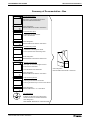
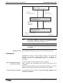
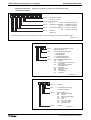
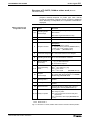
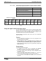
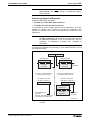
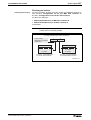
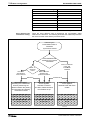
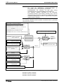
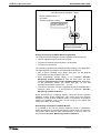
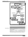
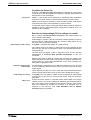
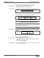
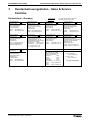
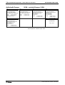
Summary of Documentation - Box
Functional Description:
Description of all implemented Function
based on SERCOS Parameters
FK
Order designation:
DOK-ECODR3-FGP-03VRS**-FK02-EN-P
282801
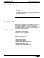
Parameter Description:
A description of all parameters
used in the firmware
PA
Order designation:
DOK-ECODR3-FGP-03VRS**-PA01-EN-P
282801
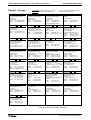
Troubleshooting Guide:
-Explanation of the diagnostic states
-How to proceed when eliminating faults
WA
Order designation:
DOK-ECODR3-FGP-03VRS**-WA01-EN-P
282801
Firmware Version Notes:
Description of new and changed functions
in terms of the derivatives:
FV
-FWA-ECODR3-FGP-02VRS-MS
Order designation:
DOK-ECODR3-FGP-03VRS**-FV01-EN-P
282801
Project Planning Manual:
-Planning control cabinet construction
-Planning the electric layout in the control cabinet
PR
Order designation:
DOK-ECODR3-DKC**.3****-PRxx-EN-P
282801
CD: DRIVEHELP
Win3.1 and
Win95&NT
epart
V
282411
01
rsion:
number:
(6-:),)04
Collection of Windows help systems which
contain documents on firmware derivatives
Order designation:
DOK-GENERL-DRIVEHELP**-GExx-MS-D0600
DOK-ECODR3-FGP-03VRS**-FK02-EN-P
Order designation
DOK-ECODR3-FGP-03VRS**-7302-EN-P
About this Documentation
ECODRIVE03 FGP-03VRS
Notes
DOK-ECODR3-FGP-03VRS**-FK02-EN-P
ECODRIVE03 FGP-03VRS
Contents I
Contents
1
System Overview
1-1
1.1
ECODRIVE03 - the Universal Drive Solution for Automation ........................................................ 1-1
1.2
ECODRIVE03 - a Drive Family ...................................................................................................... 1-1
1.3
Drive Controllers and Motors ......................................................................................................... 1-2
1.4
Function Overview: FWA-ECODR3-FGP-03VRS-MS ................................................................... 1-3
Command Communications Interface ..................................................................................... 1-3
Supported Profile Types .......................................................................................................... 1-3
Supported Types of Motors...................................................................................................... 1-3
Supported Measuring Systems................................................................................................ 1-4
Firmware Functions ................................................................................................................. 1-5
2
3
Important directions for use
2-1
2.1
Introduction..................................................................................................................................... 2-1
2.2
Inappropriate use ........................................................................................................................... 2-2
Safety Instructions for Electric Servo Drives and Controls
3-1
3.1
Introduction..................................................................................................................................... 3-1
3.2
Explanations................................................................................................................................... 3-1
3.3
Hazards by inappropriate use ........................................................................................................ 3-2
3.4
General Information ....................................................................................................................... 3-3
3.5
Protection against contact with electrical parts .............................................................................. 3-4
3.6
Protection by protective low voltage (PELV) against electrical shock ........................................... 3-6
3.7
Protection against dangerous movements..................................................................................... 3-6
3.8
Protection against magnetic and electromagnetic fields during operations and mounting............ 3-8
3.9
Protection against contact with hot parts ....................................................................................... 3-9
3.10 Protection during handling and installation .................................................................................... 3-9
3.11 Battery safety ............................................................................................................................... 3-10
3.12 Protection against pressurized Systems...................................................................................... 3-10
4
General Instructions for Installation
4.1
4-1
Definition of Terms, Introduction .................................................................................................... 4-1
Parameter ................................................................................................................................ 4-1
Data Storage ............................................................................................................................ 4-2
Password ................................................................................................................................. 4-5
Commands............................................................................................................................... 4-6
Operating Modes ..................................................................................................................... 4-8
Warnings .................................................................................................................................. 4-9
Error ......................................................................................................................................... 4-9
DOK-ECODR3-FGP-03VRS**-FK02-EN-P
II Contents
ECODRIVE03 FGP-03VRS
IDN List of Parameters........................................................................................................... 4-10
4.2
Parametrization Mode - Operating Mode..................................................................................... 4-12
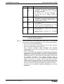
Checks in the Transition Commands..................................................................................... 4-13
4.3
Commissioning Guidelines........................................................................................................... 4-16
4.4
Diagnostic Configurations ............................................................................................................ 4-22
Overview of Diagnostic Configurations.................................................................................. 4-22
Drive-Internal Diagnostics...................................................................................................... 4-22
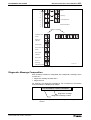
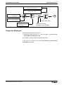
Diagnostic Message Composition ......................................................................................... 4-23
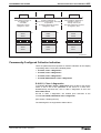
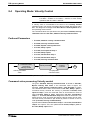
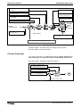
Permanently-Configured Collective Indication....................................................................... 4-25
4.5
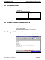
Language Selection ..................................................................................................................... 4-29
4.6
Firmware Update with the Dolfi Program ..................................................................................... 4-29
Error Message in the Firmware Loader ................................................................................. 4-29
Additional Problems when Loading Firmware ....................................................................... 4-32
5
Command Communication via Fieldbus
5.1
5-1
Bus-Independent Features............................................................................................................. 5-1
Profile ....................................................................................................................................... 5-1
Pertinent Parameters ............................................................................................................... 5-1
Object mapping........................................................................................................................ 5-2
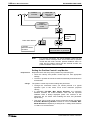
Setting the Slave Address........................................................................................................ 5-3
Drive Parametrization via Fieldbus .......................................................................................... 5-4
5.2
Command Communications with PROFIBUS-DP.......................................................................... 5-9
General Information ................................................................................................................. 5-9
Function Overview ................................................................................................................. 5-10
PROFIBUS Interface.............................................................................................................. 5-10
Setting a Slave Address and Transmission Rates ................................................................ 5-10
Parameter Channel in the DP ................................................................................................ 5-11
Object Directory PROFIBUS Specific .................................................................................... 5-20
Unit master file for DKC03.3 .................................................................................................. 5-20
Configuration of the PROFIBUS-DP Slave............................................................................ 5-20
Length of the process data channel PD in ECODRIVE 03.................................................... 5-21
Configuration via SET_PRM Service of PROFIBUS-DP ....................................................... 5-22
Diagnostic LEDs for PROFIBUS............................................................................................ 5-22
Assigning PROFIBUS Plug-In Connector X30 ...................................................................... 5-23
5.3
Command Communications with INTERBUS-S .......................................................................... 5-23
General Information ............................................................................................................... 5-23
Functional Overview .............................................................................................................. 5-23
INTERBUS-S Interface .......................................................................................................... 5-24
Setting Slave Addresses and Transmission Rates (bus-specific) ......................................... 5-24
PCP services.......................................................................................................................... 5-24
Object Directory INTERBUS-specific..................................................................................... 5-25
Configuration of INTERBUS Slave ........................................................................................ 5-26
Length of process data channel in the ECODRIVE 03.......................................................... 5-31
Diagnostic LEDs for INTERBUS ............................................................................................ 5-33
Assignment INTERBUS-S - connectors X40 / X41................................................................ 5-33
5.4
Command communications with CANopen ................................................................................. 5-33
DOK-ECODR3-FGP-03VRS**-FK02-EN-P
ECODRIVE03 FGP-03VRS
Contents III
General Information ............................................................................................................... 5-33
Functional Overview .............................................................................................................. 5-34
CANopen Interface ................................................................................................................ 5-34
Setting the Slave Address and Transmission Rates (bus-specific) ....................................... 5-34
SDO Services ........................................................................................................................ 5-35
Electronic Data Sheet for DKC05.3 ....................................................................................... 5-35
Object Directory CANopen specific ....................................................................................... 5-35
Configuration of CANopen Slave........................................................................................... 5-36
Number and length of PDO in ECODRIVE 03....................................................................... 5-37
Diagnoses LED for CANopen ................................................................................................ 5-37
Assignment of CANopen Connectors X50............................................................................. 5-38
5.5
Command communications with DeviceNet ................................................................................ 5-39
General Information ............................................................................................................... 5-39
Functional Overview .............................................................................................................. 5-39
DeviceNet Interface ............................................................................................................... 5-40
Setting the Slave Address and Transmission Rates (bus-specific) ....................................... 5-40
Explicit Message .................................................................................................................... 5-40
Electronic Data Sheet for DKC06.3 ....................................................................................... 5-40
Object Directory DeviceNet specific ...................................................................................... 5-41
Configuration of DeviceNet Slave.......................................................................................... 5-42
Number and length of Polled I/O in DKC06.3 ........................................................................ 5-43
Diagnose-LED for DeviceNet................................................................................................. 5-43
6
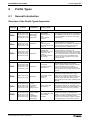
Profile Types
6.1
6-1
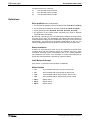
General Introduction....................................................................................................................... 6-1
Overview of the Profile Types Supported ................................................................................ 6-1
Definitions ................................................................................................................................ 6-2
Allocation to Drive-Internal Modes ........................................................................................... 6-3
6.2
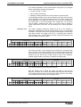
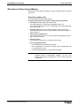
I/O Mode......................................................................................................................................... 6-4
Basic I/O mode function........................................................................................................... 6-4
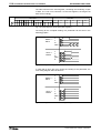
Status machine in I/O mode (Fieldbus control and status word) ............................................. 6-5
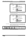
I/O Mode-Default Setting ......................................................................................................... 6-8
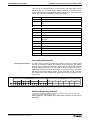
I/O mode with cam ( P-0-4084= 0xFF81 ) ............................................................................... 6-8
I/O mode freely expandable ( P-0-4084= 0xFF82) .................................................................. 6-9
6.3
Rexroth Indramat specific profile types.......................................................................................... 6-9
Basic function of Rexroth Indramat Profile .............................................................................. 6-9
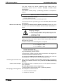
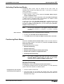
"Rexroth Indramat status machine" of the drives..................................................................... 6-9
Drive-internal interpolation ( P-0-4084= 0xFF91) .................................................................. 6-13
Cyclic Position Control (P-0-4084= 0xFF92) ......................................................................... 6-14
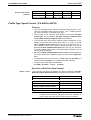
Profile Type, Speed Control ( P-0-4084= 0xFF93) ................................................................ 6-15
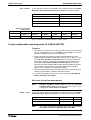
Freely configurable operating mode (P-0-4084=0xFFFE) ..................................................... 6-16
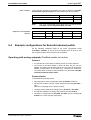
6.4
Example configurations for Rexroth Indramat profile................................................................... 6-17
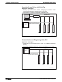
Operating with analog setpoints (Fieldbus master not active)............................................... 6-17
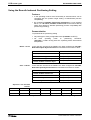
Using the Rexroth Indramat Positioning Setting .................................................................... 6-18
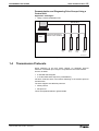
Using the multiplex channel in positioning block mode ......................................................... 6-19
Using the signal control and status words ............................................................................. 6-20
DOK-ECODR3-FGP-03VRS**-FK02-EN-P
IV Contents
ECODRIVE03 FGP-03VRS
Cam mode with real master axis ........................................................................................... 6-21
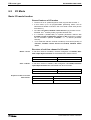
6.5
Multiplex Channel......................................................................................................................... 6-23
Overview ................................................................................................................................ 6-23
Pertinent Parameters ............................................................................................................. 6-23
Functional Principle Multiplex Channel.................................................................................. 6-23
Diagnostic Messages............................................................................................................. 6-26
7
Motor Configuration
7.1
7-1
Characteristics of the Different Motor Types.................................................................................. 7-1
Motor Feedback-Data Memory ................................................................................................ 7-2
Linear-Rotational...................................................................................................................... 7-2
Synchronous-Asynchronous .................................................................................................... 7-3
Temperature Monitoring........................................................................................................... 7-3
Load Default Feature ............................................................................................................... 7-4
7.2
Setting the Motor Type................................................................................................................... 7-4
Automatic Setting of the Motor Type for Motors with Feedback Memory................................ 7-4
Setting of the Motor Type through P-0-4014, Motor Type ....................................................... 7-5
7.3
Asynchronous Motors .................................................................................................................... 7-5
Basics for the Asynchronous Motor ......................................................................................... 7-5
Torque Evaluation.................................................................................................................... 7-6
User-defined Settings for the Asynchronous Motor ................................................................. 7-7
7.4
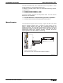
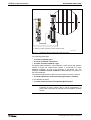
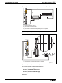
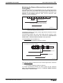
Synchronous Motors ...................................................................................................................... 7-9
Starting up Synchronous Kit Motors ...................................................................................... 7-11
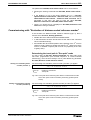
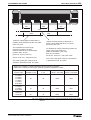
Determining commutation offset ............................................................................................ 7-11
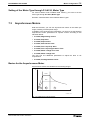
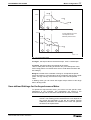
Fieldweakening range for synchronous motors ..................................................................... 7-18
7.5
Motor Holding Brake .................................................................................................................... 7-19
Pertinent Parameters ............................................................................................................. 7-19
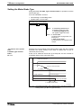
Setting the Motor Brake Type ................................................................................................ 7-20
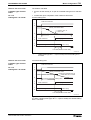
Setting the Motor Brake Integral Action Time ........................................................................ 7-22
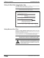
Setting Maximum Decel Time................................................................................................ 7-22
Command Release motor holding brake ............................................................................... 7-23
Monitoring the Motor Holding Brake ...................................................................................... 7-23
Connecting the Motor Holding Brake..................................................................................... 7-24
8
Operating Modes
8-1
8.1
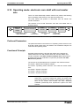
Setting the Operating Mode Parameters ....................................................................................... 8-1
8.2
Determining/detecting the active mode.......................................................................................... 8-1
8.3
Operating Mode: Torque Control ................................................................................................... 8-2
Pertinent Parameters ............................................................................................................... 8-2
Torque Control ......................................................................................................................... 8-2
Diagnostic Messages............................................................................................................... 8-3
8.4
Operating Mode: Velocity Control .................................................................................................. 8-4
Pertinent Parameters ............................................................................................................... 8-4
Command value processing Velocity control........................................................................... 8-4
Velocity Controller .................................................................................................................... 8-5
Current Controller .................................................................................................................... 8-6
DOK-ECODR3-FGP-03VRS**-FK02-EN-P
ECODRIVE03 FGP-03VRS
Contents V
Diagnostic Messages............................................................................................................... 8-7
8.5
Operating Mode: Position Control.................................................................................................. 8-7
Command value processing: Position Control......................................................................... 8-8
Position Controller.................................................................................................................... 8-9
Position Command Value Monitoring .................................................................................... 8-10
Setting Position Command Value Monitoring ........................................................................ 8-10
8.6
Operating Mode: Drive Internal Interpolation ............................................................................... 8-11
Pertinent Parameters ............................................................................................................. 8-11
Functional Principle................................................................................................................ 8-11
Monitoring and Diagnosing .................................................................................................... 8-13
Status messages ................................................................................................................... 8-14
8.7
Operating Mode: Drive Controlled Positioning............................................................................. 8-15
Pertinent Parameter............................................................................................................... 8-16
Functional Principle................................................................................................................ 8-16
Acknowledging command value latch.................................................................................... 8-19
Monitoring and Diagnoses ..................................................................................................... 8-21
Status messages ................................................................................................................... 8-21
8.8
Positioning Block Mode................................................................................................................ 8-22
Pertinent Parameters ............................................................................................................. 8-23
How it works........................................................................................................................... 8-23
Activating Positioning Blocks ................................................................................................. 8-25
Positioning Block Modes........................................................................................................ 8-25
Parametrization notes for positioning blocks ......................................................................... 8-41
Acknowledge positioning block selected ............................................................................... 8-43
Status Messages in "Positioning Block Mode" ...................................................................... 8-45
Diagnostic messages............................................................................................................. 8-45
Hardware Connections .......................................................................................................... 8-45
8.9
Operating Mode: Jogging............................................................................................................. 8-45
Pertinent Parameters ............................................................................................................. 8-45
How it works........................................................................................................................... 8-46
Diagnostic Messages............................................................................................................. 8-47
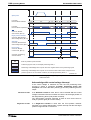
8.10 Operating mode: velocity synchronization with virtual master axis.............................................. 8-47
Pertinent Parameters ............................................................................................................. 8-47
Command Value Preparation for Velocity Synchronization with Virtual Master Axis ............ 8-47
8.11 Operating mode: velocity synchronisation with real master axis ................................................. 8-49
Pertinent Parameters ............................................................................................................. 8-49
Functional Principle................................................................................................................ 8-50
8.12 Operating mode: phase synchronisation with virtual master axis................................................ 8-50
Pertinent Parameters ............................................................................................................. 8-51
Command value preparation with phase synchronisation with virtual master axis ............... 8-51
8.13 Operating mode: phase synchronization with real master axis ................................................... 8-56
Pertinent Parameters ............................................................................................................. 8-56
Functional Principle................................................................................................................ 8-57
8.14 Operating mode: electronic cam shaft with virtual master axis.................................................... 8-57
Pertinent Parameters ............................................................................................................. 8-58
Command Value Preparation for Electronic Cam.................................................................. 8-58
DOK-ECODR3-FGP-03VRS**-FK02-EN-P
VI Contents
ECODRIVE03 FGP-03VRS
8.15 Operating mode: electronic cam shaft with real master axis ....................................................... 8-61
Pertinent Parameters ............................................................................................................. 8-61
Functional Principle................................................................................................................ 8-61
9
Basic Drive Functions
9.1
9-1
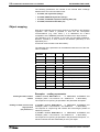
Physical Values Display Format .................................................................................................... 9-1
Adjustable Scaling for Position, Velocity, and Acceleration Data ............................................ 9-1
Display Format of Position Data .............................................................................................. 9-3
Velocity Data Display Format .................................................................................................. 9-4
Acceleration Data Display Format ........................................................................................... 9-4
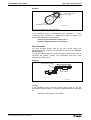
Command Polarities and Actual Value Polarities .................................................................... 9-5
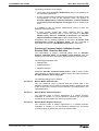
Mechanical Transmission Elements ........................................................................................ 9-6
Modulo Feature........................................................................................................................ 9-8
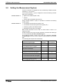
9.2
Setting the Measurement System................................................................................................ 9-10
Motor Encoder ....................................................................................................................... 9-11
Optional encoder.................................................................................................................... 9-14
Actual Feedback Values of Non-Absolute Measurement Systems After Initialization........... 9-19
Drive-internal format of position data..................................................................................... 9-20
9.3
Supplementary Settings for Absolute Measuring Systems.......................................................... 9-24
Encoder Types and Relevant Interfaces................................................................................ 9-24
Absolute encoder range and absolute encoder evaluation ................................................... 9-25
Absolute Encoder Monitoring................................................................................................. 9-26
Modulo Evaluation of Absolute Measuring Systems ............................................................. 9-27
Actual position values of absolute measuring systems after initialization ............................. 9-27
9.4
Drive Limitations........................................................................................................................... 9-28
Current Limit .......................................................................................................................... 9-28
Torque Limit ........................................................................................................................... 9-32
Limiting Velocity ..................................................................................................................... 9-35
Travel Range Limits ............................................................................................................... 9-36
9.5
Master Axis Feedback Analysis ................................................................................................... 9-41
The Functional Principle of Master Axis Feedback Analysis ................................................. 9-41
Parameterizing the Master Axis Feedback ............................................................................ 9-41
Referencing the master axis encoder .................................................................................... 9-43
9.6
Drive Error Reaction..................................................................................................................... 9-44
Best Possible Deceleration .................................................................................................... 9-44
Power off on error .................................................................................................................. 9-50
NC Response in Error Situation............................................................................................. 9-53
Emergency stop feature......................................................................................................... 9-53
9.7
Control Loop Settings................................................................................................................... 9-55
General Information for Control Loop Settings ...................................................................... 9-55
Load Default........................................................................................................................... 9-57
Setting the Current Controller ................................................................................................ 9-58
Setting the Velocity Controller................................................................................................ 9-59
Velocity Control Loop Monitoring ........................................................................................... 9-63
Setting the position controller................................................................................................. 9-64
Position Control Loop Monitoring........................................................................................... 9-65
DOK-ECODR3-FGP-03VRS**-FK02-EN-P
ECODRIVE03 FGP-03VRS
Contents VII
Setting the Acceleration Feed Forward ................................................................................. 9-67
Setting the Velocity Mix Factor .............................................................................................. 9-68
9.8
Automatic Control Loop Settings ................................................................................................. 9-69
General Comments................................................................................................................ 9-69
Prerequisites for starting the automatic control loop settings ................................................ 9-69
Conducting Automatic Control Loop Settings ........................................................................ 9-72
Chronological Sequence of Automatic Control Loop Settings............................................... 9-74
Results of Automatic Control Loop Settings .......................................................................... 9-76
9.9
Drive Halt...................................................................................................................................... 9-77
Pertinent Parameters ............................................................................................................. 9-77
The Functional Principle of Drive Halt ................................................................................... 9-78
Connecting the drive halt input .............................................................................................. 9-79
9.10 Drive-Controlled Homing.............................................................................................................. 9-79
Pertinent Parameter............................................................................................................... 9-80
Setting the referencing parameters ....................................................................................... 9-80
Overview of the Type and Allocation of Reference Marks of Non-Absolute Measuring Systems9-81
Functional Principle of Drive-Controlled Referencing in Non-Absolute Measuring Systems 9-82
Functional Principle of Drive-Guided Referencing with Absolute Measuring Systems ......... 9-83
Sequence control "Drive-Controlled Homing"........................................................................ 9-84
Commissioning with "Evaluation of reference marker/home switch edge"............................ 9-87
Commissioning with "Evaluation of distance-coded reference marker" ................................ 9-93
Functions of the Control During "Drive-Controlled Homing".................................................. 9-98
Possible Error Messages During "Drive-Controlled Homing" ................................................ 9-98
Configuration of the Home switch.......................................................................................... 9-99
Connection of the Home switch ............................................................................................. 9-99
9.11 Setting the Absolute Dimension................................................................................................. 9-100
Pertinent Parameters ........................................................................................................... 9-100
Functional Principle.............................................................................................................. 9-100
Actual Position Value after Setting the absolute dimension ................................................ 9-105
Actual position value of absolute encoders after power on ................................................. 9-105
Diagnostic messages........................................................................................................... 9-105
Hardware Connections ........................................................................................................ 9-105
10 Optional Drive Functions
10-1
10.1 Configurable Signal Status Word................................................................................................. 10-1
Pertinent Parameters ............................................................................................................. 10-1
Configuration of the Signal Status Word................................................................................ 10-1
Diagnostic / Error Messages.................................................................................................. 10-2
10.2 Configurable Signal Control Word ............................................................................................... 10-3
Involved Parameters .............................................................................................................. 10-3
Configuring the Signal Control Word ..................................................................................... 10-3
Diagnostic / Error Messages.................................................................................................. 10-5
10.3 Analog Output .............................................................................................................................. 10-5
Possible output functions ....................................................................................................... 10-5
Direct analog outputs ............................................................................................................. 10-6
Analog output of existing parameters .................................................................................... 10-6
DOK-ECODR3-FGP-03VRS**-FK02-EN-P
VIII Contents
ECODRIVE03 FGP-03VRS
Outputting pre-set signals ...................................................................................................... 10-6
Bit and byte outputs of the data memory ............................................................................... 10-8
Terminal assignment - analog output .................................................................................... 10-8
10.4 Analog Inputs ............................................................................................................................... 10-9
Pertinent Parameters ............................................................................................................. 10-9
Functional principle of the analog inputs ............................................................................... 10-9
Analog Inputs - Connection.................................................................................................. 10-10
10.5 Digital Output ............................................................................................................................. 10-11
Pertinent Parameters ........................................................................................................... 10-11
Functional Principle.............................................................................................................. 10-11
Hardware Requirements ...................................................................................................... 10-12
10.6 Oscilloscope Feature ................................................................................................................. 10-12
Main Functions of the Oscilloscope Feature........................................................................ 10-13
Parameterizing the Oscilloscope Feature............................................................................ 10-13
10.7 Probe Input Feature ................................................................................................................... 10-19
Pertinent Parameters for the Probe Analysis....................................................................... 10-19
Main Function of the Probe Analysis ................................................................................... 10-20
Signal Edge Selection for the Probe Inputs ......................................................................... 10-21
Signal Selection for the Probe Inputs .................................................................................. 10-22
Connecting the Probe Inputs ............................................................................................... 10-23
10.8 Positive stop drive procedure..................................................................................................... 10-23
10.9 Command - detect marker position............................................................................................ 10-24
Functional principle of command detect marker position .................................................... 10-24
10.10Command Parking Axis.............................................................................................................. 10-25
Pertinent Parameters ........................................................................................................... 10-25
Functional principle .............................................................................................................. 10-25
10.11Programmable Limit Switch ....................................................................................................... 10-26
Pertinent Parameters ........................................................................................................... 10-26
Function diagram for the Programmable Limit Switch......................................................... 10-26
Parameterizing the Programmable Limit Switch................................................................. 10-28
10.12Encoder Emulation..................................................................................................................... 10-29
Pertinent Parameters ........................................................................................................... 10-29
Activating Encoder Emulation .............................................................................................. 10-30
Functional principle: Incremental Encoder Emulation ......................................................... 10-30
Diagnostic Messages with Incremental Encoder Emulation................................................ 10-32
Functional Principle: Absolute Encoder Emulation .............................................................. 10-32
10.13Measuring wheel operation mode.............................................................................................. 10-34
Pertinent Parameters ........................................................................................................... 10-35
The Functional Principle ...................................................................................................... 10-35
Diagnostic Messages........................................................................................................... 10-37
11 Glossar
11-1
12 Index
12-1
DOK-ECODR3-FGP-03VRS**-FK02-EN-P
System Overview 1-1
ECODRIVE03 FGP-03VRS
1
System Overview
1.1
ECODRIVE03 - the Universal Drive Solution for
Automation
The universal automation system ECODRIVE03 is an especially costeffective solution for drive and control tasks.
The servo drive system ECODRIVE03 features:
• a very broad implementation range
• extensively integrated functionalities
• a highly favorable price/performance ratio
Further features of ECODRIVE03 are its easy assembly and installation,
extreme machine accessing and the elimination of system components.
ECODRIVE03 can be used to implement numerous drive tasks in the
most varying of applications. Typical applications are:
• machine tools
• printing and paper processing machines
• handling systems
• packaging and food processing machines
• handling and assembly systems
1.2
ECODRIVE03 - a Drive Family
FWA-ECODR3-FGP-0xVRS-MS
In addition to the here documented firmware FWA-ECODR3-FGP03VRS-MS drive for general automation with fieldbus interfaces, there are
also two additional application-related firmware variants.
FWA-ECODR3-SMT-0xVRS-MS
• drive for machine tool applications with SERCOS, analog and parallel
interface
FWA-ECODR3-SGP-0xVRS-MS
• drive for general automation with SERCOS, analog and parallel
interface
DOK-ECODR3-FGP-03VRS**-FK02-EN-P
1-2 System Overview
1.3
ECODRIVE03 FGP-03VRS
Drive Controllers and Motors
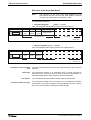
Available controllers
The drive controller family of the ECODRIVE03 generation is at present
made up of eight different units. These differentiate primarily in terms of
which interface is used command communications.
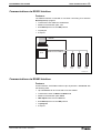
• DKC01.3
Parallel interface
• DKC11.3
Analog interface
• DKC21.3
Parallel interface 2
• DKC02.3
SERCOS interface
• DKC03.3
Profibus-DP interface
• DKC04.3
InterBus interface
• DKC05.3
CANopen interface
• DKC06.3
DeviceNet interface
Each of these drive controllers is, in turn, available in a 40 A, 100 A or a
200 A version.
Supported motor types
With ECODRIVE03 firmware it is possible to operate
• synchronous motors for standard applications up to 48 Nm.
• synchronous motors for increased demands of up to 64 Nm.
• asynchronous motors for main spindle applications
• asynchronous kit motors
• linear synchronous and asynchronous motors
DOK-ECODR3-FGP-03VRS**-FK02-EN-P
System Overview 1-3
ECODRIVE03 FGP-03VRS
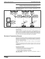
1.4
Function Overview: FWA-ECODR3-FGP-03VRS-MS
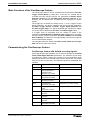
Command Communications Interface
• Profibus-DP interface
• CANopen interface
• InterBus interface
• Analog interface
• DeviceNet interface
Supported Profile Types
• I/O mode with block acknowledge (functionally compatible with
DKC3.1)
• I/O mode with cam status
• I/O mode free expandable + expandable real time data channel
• drive-internal interpolation
• cyclical position control
• velocity control
• free configurable mode (without profile interpreter)
Supported Types of Motors
• MKD
• 2AD
• 1MB
• LAF
• MKE
• MBS
• MHD
• ADF
• MBW
• LAR
• LSF
DOK-ECODR3-FGP-03VRS**-FK02-EN-P
1-4 System Overview
ECODRIVE03 FGP-03VRS
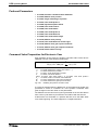
Supported Measuring Systems
• HSF/LSF
• resolver
• sine encoder with 1Vss signals
• encoder with EnDat-Interface
• resolver without feedback data memory
• resolver without feedback data memory with incremental sine encoder
• gearwheel encoder with 1Vss signals
• Hall encoder + square-wave encoder
• Hall encoder + sine encoder
Which combination is possible, is outlined in section: "Setting the
Measurement System"
DOK-ECODR3-FGP-03VRS**-FK02-EN-P
System Overview 1-5
ECODRIVE03 FGP-03VRS
Firmware Functions
• Extensive diagnostics options
• Basic parameter block that can be activated for a defined setting of the
drive parameters to default values.
• Customer passwords
• List of password-protected data
• Error memory and operating hour counter
• Supports five (5) languages for parameter names and units and
diagnoses (S-0-0095)
• German
• English
• French
• Spanish
• Italian
• Settable drive-internal position resolution
• Evaluation of option (load-side) encoder for position and/or velocity
control
• Evaluates absolute measuring system with setting of absolute
dimension
• Modulo function
• Parametrizable torque limit
• Current limit
• Velocity limit
• Travel range limit:
• via travel range limit switch and/or
• position limit values
• Drive-side error reactions:
• error reaction "return limit"
• best possible standstill "velocity command to zero"
• best possible standstill "Torque free"
• best possible standstill "velocity command to zero with ramp and
filter
• power shutdown with fault
• NC reaction with fault
• E-Stop function
• Control loop settings
• base load function
• acceleration precontrol
• velocity mix factor
• velocity precontrol
• automatic control loop settings
• Velocity control loop monitor
• Position control loop monitor
• Drive halt
DOK-ECODR3-FGP-03VRS**-FK02-EN-P
1-6 System Overview
ECODRIVE03 FGP-03VRS
• Command "Drive-controlled homing"
• Command "Set Absolute Measuring"
• Analog output
• Analog input
• Oscilloscope function
• Probe function
• Command "Parking Axis"
• Command "Detect marker position"
• Command "Positive stop drive procedure"
• Command "Measuring wheel operation mode"
• Dynamic cam switch group
• Encoder emulation
• absolute encoder emulation (SSI format)
• incremental encoder emulation
DOK-ECODR3-FGP-03VRS**-FK02-EN-P
Important directions for use 2-1
ECODRIVE03 FGP-03VRS
2
Important directions for use
2.1
Introduction
Rexroth Indramat products represent state-of-the-art developments and
manufacturing. They are tested prior to delivery to ensure operating safety
and reliability.
The products may only be used in the manner that is defined as
appropriate. If they are used in an inappropriate manner, then situations
can develop that may lead to property damage or injury to personnel.
Note:
Rexroth Indramat, as manufacturer, is not liable for any
damages resulting from inappropriate use. In such cases, the
guarantee and the right to payment of damages resulting from
inappropriate use are forfeited. The user alone carries all
responsibility of the risks.
Before using Rexroth Indramat products, make sure that all the prerequisites for an appropriate use of the products are satisfied:
• Personnel that in any way, shape or form uses our products must first
read and understand the relevant safety instructions and be familiar
with appropriate use.
• If the product takes the form of hardware, then they must remain in
their original state, in other words, no structural changes are permitted.
It is not permitted to decompile software products or alter source
codes.
• Do not mount damaged or faulty products or use them in operation.
• Make sure that the products have been installed in the manner
described in the relevant documentation.
DOK-ECODR3-FGP-03VRS**-FK02-EN-P
2-2 Important directions for use
2.2
ECODRIVE03 FGP-03VRS
Inappropriate use
The use of the firmware and the drive controllers outside of applications
other than specified in the system overview or under operating conditions
other than those specified in the project planning manual and not with the
use of the specified technical data is defined as “inappropriate use”.
Drive controllers may not be used if
•
they are subject to operating conditions that do not meet the above
specified ambient conditions. This includes, for example, operation
under water, in the case of extreme temperature fluctuations or
extremely high maximum temperatures or if
•
Rexroth Indramat has not specifically released them for that intended
purpose. Please note the specifications outlined in the general safety
instructions!
DOK-ECODR3-FGP-03VRS**-FK02-EN-P
ECODRIVE03 FGP-03VRS
Safety Instructions for Electric Servo Drives and Controls 3-1
3
Safety Instructions for Electric Servo Drives and
Controls
3.1
Introduction
Read these instructions before the equipment is used and eliminate the
risk of personal injury or property damage. Follow these safety
instructions at all times.
Do not attempt to install, use or service this equipment without first
reading all documentation provided with the product. Read and
understand these safety instructions and all user documentation of the
equipment prior to working with the equipment at any time. If you do not
have the user documentation for your equipment contact your local
Rexroth Indramat representative to send this documentation immediately
to the person or persons responsible for the safe operation of this
equipment.
If the product is resold, rented or transferred or passed on to others, then
these safety instructions must be delivered with the product.
WARNING
3.2
Inappropriate use of this equipment, failure to
follow the safety instructions in this document
or tampering with the product, including
disabling of safety devices, may result in
product damage, personal injury, severe
electrical shock or death!
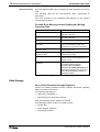
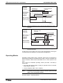
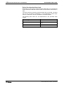
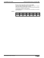
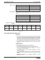
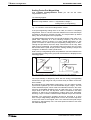
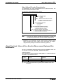
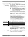
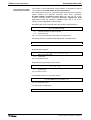
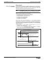
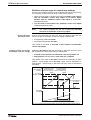
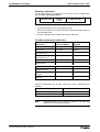
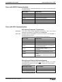
Explanations
The safety warnings in this documentation describe individual degrees of
hazard seriousness in compliance with ANSI:
Warning symbol with signal
word
Degree of hazard seriousness
The degree of hazard seriousness
describes the consequences resulting
from non-compliance with the safety
guidelines.
Bodily harm or product damage will occur.
DANGER
Death or severe bodily harm may occur.
WARNING
Death or severe bodily harm may occur.
CAUTION
Fig. 3-1: Classes of danger with ANSI
DOK-ECODR3-FGP-03VRS**-FK02-EN-P
3-2 Safety Instructions for Electric Servo Drives and Controls
3.3
ECODRIVE03 FGP-03VRS
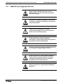
Hazards by inappropriate use
High voltage and high discharge current!
Danger to life, risk of severe electrical shock
and risk of injury!
DANGER
Dangerous movements! Danger to life and risk
of injury or equipment damage by unintentional
motor movements!
DANGER
High electrical voltage due to wrong
connections! Danger to life, severe electrical
shock and severe bodily injury!
WARNING
Health hazard for persons with heart
pacemakers, metal implants and hearing aids in
proximity to electrical equipment!
WARNING
Surface of machine housing could be extremely
hot! Danger of injury! Danger of burns!
CAUTION
CAUTION
Risk of injury due to inappropriate handling!
Bodily injury caused by crushing, shearing,
cutting and mechanical shock or improper
handling of pressurized systems!
Risk of injury due to inappropriate handling of
batteries!
CAUTION
DOK-ECODR3-FGP-03VRS**-FK02-EN-P
ECODRIVE03 FGP-03VRS
3.4
Safety Instructions for Electric Servo Drives and Controls 3-3
General Information
• Rexroth Indramat GmbH is not liable for damages resulting from
failure to observe the warnings given in these documentation.
• Order operating, maintenance and safety instructions in your language
before starting up the machine. If you find that due to a translation
error you can not completely understand the documentation for your
product, please ask your supplier to clarify.
• Proper and correct transport, storage, assembly and installation as
well as care in operation and maintenance are prerequisites for
optimal and safe operation of this equipment.
• Trained and qualified personnel in electrical equipment:
Only trained and qualified personnel may work on this equipment or
within its proximity. Personnel are qualified if they have sufficient
knowledge of the assembly, installation and operation of the product
as well as an understanding of all warnings and precautionary
measures noted in these instructions.
Furthermore, they should be trained, instructed and qualified to switch
electrical circuits and equipment on and off, to ground them and to
mark them according to the requirements of safe work practices and
common sense. They must have adequate safety equipment and be
trained in first aid.
• Only use spare parts and accessories approved by the manufacturer.
• Follow all safety regulations and requirements for the specific
application as practiced in the country of use.
• The equipment is designed for installation on commercial machinery.
European countries: see directive 89/392/EEC (machine guideline).
• The ambient conditions given in the product documentation must be
observed.
• Use only safety features that are clearly and explicitly approved in the
Project Planning manual.
For example, the following areas of use are not allowed: Construction
cranes, Elevators used for people or freight, Devices and vehicles to
transport people, Medical applications, Refinery plants, the transport
of hazardous goods, Radioactive or nuclear applications, Applications
sensitive to high frequency, mining, food processing, Control of
protection equipment (also in a machine).
• Start-up is only permitted once it is sure that the machine, in which the
product is installed, complies with the requirements of national safety
regulations and safety specifications of the application.
• Operation is only permitted if the national EMC regulations for the
application are met.
The instructions for installation in accordance with EMC requirements
can be found in the INDRAMAT document "EMC in Drive and Control
Systems”.
The machine builder is responsible for compliance with the limiting
values as prescribed in the national regulations and specific EMC
regulations for the application.
European countries: see Directive 89/336/EEC (EMC Guideline).
U.S.A.: See National Electrical Codes (NEC), National Electrical
Manufacturers Association (NEMA), and local building codes. The user of
this equipment must consult the above noted items at all times.
• Technical data, connections and operational conditions are specified in
the product documentation and must be followed at all times.
DOK-ECODR3-FGP-03VRS**-FK02-EN-P
3-4 Safety Instructions for Electric Servo Drives and Controls
3.5
ECODRIVE03 FGP-03VRS
Protection against contact with electrical parts
Note:
This section refers to equipment with voltages above 50 Volts.
Making contact with parts conducting voltages above 50 Volts could be
dangerous to personnel and cause an electrical shock. When operating
electrical equipment, it is unavoidable that some parts of the unit conduct
dangerous voltages.
High electrical voltage! Danger to life, severe
electrical shock and severe bodily injury!
DANGER
⇒ Only those trained and qualified to work with or on
electrical equipment are permitted to operate,
maintain or repair this equipment.
⇒ Follow general construction and safety regulations
when working on electrical installations.
⇒ Before switching on power the ground wire must be
permanently connected to all electrical units according to the connection diagram.
⇒ Do not operate electrical equipment at any time if the
ground wire is not permanently connected, even for
brief measurements or tests.
⇒ Before working with electrical parts with voltage
potentials higher than 50 V, the equipment must be
disconnected from the mains voltage or power
supply.
⇒ The following should be observed with electrical
drives, power supplies, and filter components:
Wait five (5) minutes after switching off power to
allow capacitors to discharge before beginning work.
Measure the voltage on the capacitors before
beginning work to make sure that the equipment is
safe to touch.
⇒ Never touch the electrical connection points of a
component while power is turned on.
⇒ Install the covers and guards provided with the
equipment properly before switching the equipment
on. Prevent contact with live parts at any time.
⇒ A residual-current-operated protective device (r.c.d.)
must not be used on an electric drive! Indirect
contact must be prevented by other means, for
example, by an overcurrent protective device.
⇒ Equipment that is built into machines must be
secured against direct contact. Use appropriate
housings, for example a control cabinet.
European countries: according to EN 50178/1998,
section 5.3.2.3.
U.S.A: See National Electrical Codes (NEC), National
Electrical Manufacturers Association (NEMA) and local
building codes. The user of this equipment must observe
the above noted instructions at all times.
DOK-ECODR3-FGP-03VRS**-FK02-EN-P
ECODRIVE03 FGP-03VRS
Safety Instructions for Electric Servo Drives and Controls 3-5
To be observed with electrical drives, power supplies, and filter
components:
High electrical voltage! High leakage current!
Danger to life, danger of injury and bodily harm
from electrical shock!
DANGER
⇒ Before switching on power for electrical units, all
housings and motors must be permanently grounded
according to the connection diagram. This applies
even for brief tests.
⇒ Leakage current exceeds 3.5 mA. Therefore the
electrical equipment and units must always be firmly
connected to the supply network.
⇒ Use a copper conductor with at least 10 mm² cross
section over its entire course for this protective
connection!
⇒ Prior to startups, even for brief tests, always connect
the protective conductor or connect with ground wire.
High voltage levels can occur on the housing that
could lead to severe electrical shock and personal
injury.
European countries: EN 50178/1998, section 5.3.2.1.
USA: See National Electrical Codes (NEC), National
Electrical Manufacturers Association (NEMA), and local
building codes. The user of this equipment must maintain
the above noted instructions at all times.
DOK-ECODR3-FGP-03VRS**-FK02-EN-P
3-6 Safety Instructions for Electric Servo Drives and Controls
3.6
ECODRIVE03 FGP-03VRS
Protection by protective low voltage (PELV) against
electrical shock
All connections and terminals with voltages between 5 and 50 Volts on
INDRAMAT products are protective low voltages designed in accordance
with the following standards on contact safety:
• International: IEC 364-4-411.1.5
• EU countries: see EN 50178/1998, section 5.2.8.1.
High electrical voltage due to wrong
connections! Danger to life, severe electrical
shock and severe bodily injury!
WARNING
3.7
⇒ Only equipment, electrical components and cables of
the protective low voltage type (PELV = Protective
Extra Low Voltage)
may be connected to all
terminals and clamps with 0 to 50 Volts.
⇒ Only safely isolated voltages and electrical circuits
may be connected. Safe isolation is achieved, for
example, with an isolating transformer, an optoelectronic coupler or when battery-operated.
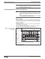
Protection against dangerous movements
Dangerous movements can be caused by faulty control or the connected
motors. These causes are be various such as:
• unclean or wrong wiring of cable connections
• inappropriate or wrong operation of equipment
• malfunction of sensors, encoders and monitoring circuits
• defective components
• software errors
Dangerous movements can occur immediately after equipment is
switched on or even after an unspecified time of trouble-free operation.
The monitors in the drive components make faulty operation almost
impossible. Regarding personnel safety, especially the danger of bodily
harm and property damage, this alone should not be relied upon to
ensure complete safety. Until the built-in monitors become active and
effective, it must be assumed in any case that some faulty drive
movements will occur. The extent of these faulty drive movements
depends upon the type of control and the state of operation.
DOK-ECODR3-FGP-03VRS**-FK02-EN-P
ECODRIVE03 FGP-03VRS
Safety Instructions for Electric Servo Drives and Controls 3-7
Dangerous movements! Danger to life and risk
of injury or equipment damage!
DANGER
⇒ Personnel protection must be secured for the above
listed reason by means of superordinate monitors or
measures.
These are instituted in accordance with the specific
situation of the facility and a danger and fault
analysis conducted by the manufacturer of the
facility. All the safety regulations that apply to this
facility are included therein. By switching off,
circumventing or if safety devices have simply not
been activated, then random machine movements or
other types of faults can occur.
Avoiding accidents, injury or property damage:
⇒ Keep free and clear of the machine’s range of
motion and moving parts. Prevent people from
accidentally entering the machine’s range of
movement:
- use protective fences
- use protective railings
- install protective coverings
- install light curtains or light barriers
⇒ Fences must be strong enough to withstand
maximum possible momentum.
⇒ Mount the emergency stop switch (E-stop) in the
immediate reach of the operator. Verify that the
emergency stop works before startup. Don’t operate
the machine if the emergency stop is not working.
⇒ Isolate the drive power connection by means of an
emergency stop circuit or use a start-inhibit system
to prevent unintentional start-up.
⇒ Make sure that the drives are brought to standstill
before accessing or entering the danger zone.
⇒ Secure vertical axes against falling or slipping after
switching off the motor power by, for example:
- Mechanically securing the vertical axes
- Adding an external brake / clamping mechanism
- Balancing and thus compensating for the vertical
axes mass and the gravitational force
The standard equipment motor brake or an external
brake controlled directly by the servo drive are not
sufficient to guarantee the safety of personnel!
DOK-ECODR3-FGP-03VRS**-FK02-EN-P
3-8 Safety Instructions for Electric Servo Drives and Controls
ECODRIVE03 FGP-03VRS
⇒ Disconnect electrical power to the equipment using a
master switch and secure the switch against
reconnection for:
- maintenance and repair work
- cleaning of equipment
- long periods of discontinued equipment use
⇒ Avoid operating high-frequency, remote control and
radio equipment near electronics circuits and supply
leads. If use of such equipment cannot be avoided,
verify the system and the plant for possible
malfunctions at all possible positions of normal use
before the first start-up. If necessary, perform a
special electromagnetic compatibility (EMC) test on
the plant.
3.8
Protection against magnetic and electromagnetic fields
during operations and mounting
Magnetic and electromagnetic fields generated by current-carrying
conductors and permanent magnets in motors represent a serious health
hazard to persons with heart pacemakers, metal implants and hearing
aids.
Health hazard for persons with heart
pacemakers, metal implants and hearing aids in
proximity to electrical equipment!
WARNING
⇒ Persons with pacemakers, metal implants and
hearing aids are not permitted to enter following
areas:
- Areas in which electrical equipment and parts are
mounted, being operated or started up.
- Areas in which parts of motors with permanent
magnets are being stored, operated, repaired or
mounted.
⇒ If it is necessary for a person with a pacemaker to
enter such an area, then a physician must be consulted prior to doing so. Pacemaker, that are already
implanted or will be implanted in the future, have a
considerable deviation in their resistance to
interference. Due to the unpredictable behavior there
are no rules with general validity.
⇒ Persons with hearing aids, metal implants or metal
pieces must consult a doctor before they enter the
areas described above. Otherwise health hazards
will occur.
DOK-ECODR3-FGP-03VRS**-FK02-EN-P
ECODRIVE03 FGP-03VRS
3.9
Safety Instructions for Electric Servo Drives and Controls 3-9
Protection against contact with hot parts
Housing surfaces could be extremely hot!
Danger of injury! Danger of burns!
CAUTION
⇒ Do not touch surfaces near the source of heat!
Danger of burns!
⇒ Wait ten (10) minutes before you access any hot
unit. Allow the unit to cool down.
⇒ Do not touch hot parts of the equipment, such as
housings, heatsinks or resistors. Danger of burns!
3.10 Protection during handling and installation
Under certain conditions unappropriate handling and installation of parts
and components may cause injuries.
Risk of injury through incorrect handling!
Bodily harm caused by crushing, shearing,
cutting and mechanical shock!
CAUTION
⇒ Observe general instructions and safety regulations
during handling installation.
⇒ Use only appropriate lifting or moving equipment.
⇒ Take precautions to avoid pinching and crushing.
⇒ Use only appropriate tools. If specified by the product
documentation, special tools must be used.
⇒ Use lifting devices and tools correctly and safely.
⇒ Wear appropriate protective clothing, e.g. safety
glasses, safety shoes and safety gloves.
⇒ Never stay under suspended loads.
⇒ Clean up liquids from the floor immediately to
prevent personnel from slipping.
DOK-ECODR3-FGP-03VRS**-FK02-EN-P
3-10 Safety Instructions for Electric Servo Drives and Controls
ECODRIVE03 FGP-03VRS
3.11 Battery safety
Batteries contain reactive chemicals in a solid housing. Inappropriate
handling may result in injuries or equipment damage.
Risk of injury through incorrect handling!
CAUTION
⇒ Do not attempt to reactivate discharged batteries by
heating or other methods (danger of explosion and
corrosion).
⇒ Never charge batteries (danger from leakage and
explosion).
⇒ Never throw batteries into a fire.
⇒ Do not dismantle batteries.
⇒ Handle with care. Incorrect extraction or installation
of a battery can damage equipment.
Note:
Environmental protection and disposal! The batteries
contained in the product should be considered as hazardous
material for land, air and sea transport in the sense of the legal
requirements (danger of explosion). Dispose batteries
separately from other refuse. Observe the legal requirements
given in the country of installation.
3.12 Protection against pressurized Systems
Certain Motors (ADS, ADM, 1MB etc.) and drives, corresponding to the
information in the Project Planning manual, must be provided with and
remain under a forced load such as compressed air, hydraulic oil, cooling
fluid or coolant. In these cases, improper handling of the supply of the
pressurized systems or connections of the fluid or air under pressure can
lead to injuries or accidents.
Danger of injury when pressurized systems are
handled by untrained personnel!
CAUTION
Note:
⇒ Do not attempt to disassemble, to open or to cut a
pressurized system.
⇒ Observe the operation restrictions of the respective
manufacturer.
⇒ Before the disassembly of pressurized systems,
lower pressure and drain off the fluid or gas.
⇒ Use suitable protective clothing (for example
protective eyewear, safety shoes and gloves)
⇒ Remove any fluid that has leaked out onto the floor
immediately.
Environmental protection and disposal! The fluids used in the
operation of the pressurized system equipment is not
environmentally compatible. Fluid that is damaging to the
environment must be disposed of separate from normal waste.
Observe the national specifications of the country of
installation.
DOK-ECODR3-FGP-03VRS**-FK02-EN-P
General Instructions for Installation 4-1
ECODRIVE03 FGP-03VRS
4
General Instructions for Installation
4.1
Definition of Terms, Introduction
It is helpful to explain the terms used in this document so that they will be
better understood.
Parameter
Communication with the drive occurs (with a few exceptions) with the
help of parameters. They can be used for
• Setting the configuration
• parametrizing the control/drive settings
• Accessing control/drive functions and commands
• Cyclical or acyclical (depending on requirements) transmission of
command and actual values
Note:
The Data Status
All of the drive’s operating data are identified by ID numbers.
Each parameter is provided with a data status, which can also be read. It
serves the following purposes:
• Identifying the validity/invalidity of the parameter
• Contains the command acknowledgement if the parameter acts as a
command
(see also Commands)
Parameter structure
There are seven different data block elements for each parameter. These
can be read/write accessed either via a user data interface by a higherranking control or a parametrization surface.
Element No.:
Designation:
Remarks:
1
ID Number
Parameter identification
2
Name
can be changed in language
selection
3
Attribute
contains data length, type and
decimal places
4
Unit
can be changed in language
selection
5
Minimum Input Value
contains the minimum input
value of the operating data
6
Maximum Input Value
contains the maximum input
value of the operating data
7
Fig. 4-1:
DOK-ECODR3-FGP-03VRS**-FK02-EN-P
Operating Data
actual parameter value
Data blocks or parameter structure
4-2 General Instructions for Installation
Write Accessibility
ECODRIVE03 FGP-03VRS
Only the operating data can be changed; all other elements can only be
read.
The operating data can be write-protected either continuously or
temporarily.
The write accessing of the operating data depends on the relevant
communications phase.
Possible Error Messages when Reading and Writing
Operating Data
Error:
Reason:
0x7002, data transmitted too short
Less bytes than the parameter is long
are sent to the drive
0x7003, data transmitted too long
More bytes than the parameter is long
are sent to the drive
0x7004, Data not changeable
The operating data is write-protected
0x7005, Data currently writeprotected
The operating data cannot be written to
in this communication phase (see
Supplement A: Parameter description)
0x7006, Data smaller than
minimum value
The operating data is smaller than its
minimal input value
0x7007, Data larger than
maximum value
The operating data is larger than its
maximum input value
0x7008, Data is not correct
The value could not be accepted as
written because internal tests lead to a
negative result
0x7009, data write protected with
password
The parameter cannot be write
accessed as the customer
password was activated in
parameter S-0-0267, Password. All
parameters listed in S-0-0192, IDNlist of backup operation data are
therefore locked.
Fig. 4-2:
Error messages while reading/writing operating data
Data Storage
Non-volatile Parameter Storage Registers
Various non-volatile parameter storage registers that buffer operating
data are contained in the drive.
The operating data apply to:
• setting the configuration or
• parametrizing the control drive settings
Each time operating data is written to it is stored.
The following modules contain non-volatile memory:
• Control drive
• Motor feedback (optional)
• Programming module
DOK-ECODR3-FGP-03VRS**-FK02-EN-P
General Instructions for Installation 4-3
ECODRIVE03 FGP-03VRS
Parameters Stored in the Digital
Drive
All operating data that apply only to the drive controller and that cannot be
changed by the user are stored in the digital drive.
This consists of the following parameters:
• S-0-0110, Amplifier peak current
• S-0-0140, Controller type
• P-0-0190, Operating hours control section
• P-0-0191, Operating hours power section
• P-0-0192, Error recorder, diagnosis number
• P-0-0193, Error recorder, operating hours control section
• P-0-0520, Hardware code
• P-0-4000, Current-zero-trim phase U
• P-0-4001, Current-zero-trim phase V
• P-0-4002, Current-amplify-trim phase U
• P-0-4003, Current-amplify-trim phase V
• P-0-4024, Test status
• P-0-4035, Trim-current
• P-0-4053, Intermediate DC bus voltage gain adjust
• P-0-4054, Resolver input offset
• P-0-4055, Resolver input, amplitude adjust
• P-0-4058, Amplifier type data
• P-0-4059, Braking resistor data
• P-0-4061, Mains voltage gain adjust
• P-0-4088, Serial number
• P-0-4089, Production index
Parameter Storage in Motor Feedback
All motor-dependent parameters are stored in the motor feedback with
MHD, MKD and MKE motors.
Additionally, parameters for the "Load Default" function and the position
encoder are stored here.
All parameters stored in the motor feedback data memory are there with
both parameter block number 0 and 7.
In parameter block number 7 (e.g., S-7-0100) the original data without
write access are stored in the motor feedback data memory. These are
copied after powering up into the parameters of parameter block number
0 (e.g., S-0-0100). Parameter block with number 0 is stored in the
programming module.
Note:
DOK-ECODR3-FGP-03VRS**-FK02-EN-P
The parameters of parameter block number 0 take effect.
4-4 General Instructions for Installation
Parameters Stored in DSM
Programming Module
ECODRIVE03 FGP-03VRS
All application parameters are stored in the programming module (control
loop, mechanical system, interface parameters and so on).
All ID numbers backed up in this module are listed in parameter
S-0-0192, IDN-list of backup operation data.
If the programming module is exchanged then these application
parameters must be read out before hand so that they can be written into
the new module after the exchange.
Note:
By switching the programming module when devices are
exchanged, the characteristics (firmware and parameter) of
the device that has been exchanged can be easily transferred
to the new device.
Data Saving
Back-up & Restore-
To save the data of the axis, all important and changeable parameters of
the axis are stored in the list S-0-0192, IDN-List of backup operation
data. By saving the parameters listed there with the control or
parametrization surface, you can obtain a complete data backup of this
axis after the first set-up (Back-up & restore function).
Note:
Parameter S-0-0269, Parameter buffer mode is insignificant
as of version FGP-02VRS as all the parameters are backed
up from that point on in a NOVRAM.
Basic parameter block
The drive parameters are fixed at delivery at the factory. By executing the
command P-0-4094, C800 Command Base-parameter load it is
possible to reproduce this state at any time. The basic parameter block is
constructed so that
• all optional drive functions are deactivated
• limit values for position are deactivated
• limit values for torque/force are set to high values
• and limit values for velocity and acceleration are set to lower values
Velocity control is the mode set.
Note:
The basic parameter block does not guarantee a matching of
the drive to the machine as well as, in some cases, to the
motor connected and the measuring systems. The relevant
settings must be made when first starting up the axis.
(See also: "Basic Drive Functions" and "Commissioning Guidelines".)
DOK-ECODR3-FGP-03VRS**-FK02-EN-P
General Instructions for Installation 4-5
ECODRIVE03 FGP-03VRS
Running the "load basic parameter block" function
automatically
The drive firmware is on the programming module. In the event of a firmware exchange (with a different number of buffered parameters), the drive
controller will detect this the next time the machine is switched on. In this
case, the message "PL" appears on the 7-segment display. By pressing
the "S1" key, the basic parameter block is activated.
Note:
Any previous parameter settings are lost with the replacement
of the firmware followed by "load base parameter block". If this
is to be prevented, then the parameters must be stored prior to
an exchange and must be reloaded after exchange and load
base parameter block.
Note:
As long as the drive displays "PL" and the command is active,
then communications via the serial interface (with DriveTop) is
not possible.
Password
The affected parameters are stored in S-0-0279, IDN-list of passwordprotected operation data. To secure these parameters against
unwanted or non-authorized changes, the customer password can be
activated.
By editing S-0-0279, IDN-list of password-protected operation data the
user can select the parameter which are to be protected with a password.
Note:
Accessing the password
Allowable symbols and length
The default value of S-0-0279, IDN-list of passwordprotected operation data corresponds to the contents of
S-0-0192, IDN-list of backup operation data.
The password is accessed with parameter S-0-0267, Password.
The password has to have:
• at least 3 symbols
• no more than ten symbols
• can only use the letters a - z and A - Z
• and the numbers 0 to 9.
3 different password states are
possible
The password function can have three different states. Depending on the
sequence of symbols entered for S-0-0267 the current password status
can be changed.
The following illustrates possible password states and the symbol
sequence for parameter S-0-0267.
DOK-ECODR3-FGP-03VRS**-FK02-EN-P
4-6 General Instructions for Installation
ECODRIVE03 FGP-03VRS
No customer password active
writing to parameter
contents S-0-0267: "007"(defaults)
Input string:
007_Kpassw_Kpassw
Input string:
Kpassw_007_007
Customer password active and open
writing to parameter,
contents S-0-0267: "$$$"
Input:
any string
without space
or switch off
Input:
customer password
Customer password active and closed
parameter write protected
contents S-0-0267: "***"
Kpassw.:customer password
_: space
Master password
FS0212f1.fh7
Fig. 4-3:
Possible password states
Note:
If the user’s password is activated and unlocked (content
of S-0-0267= "$$$"), then the drive is locked after switching
the machine off (contents of S-0-0267= "***").
Note:
As long as the drive displays "PL" and the command is active,
then communications via the serial interface (with DriveTop) is
not possible.
Rexroth Indramat retains the rights to the master password function.
Commands
Commands are used to control complex functions in the drive. For
example, the functions "Drive-Controlled Homing Procedure" or
"Transition Check for Communication Phase 4" are defined as
commands.
Each command that is started
must also be cleared.
A primary control can start, interrupt or erase a command.
Each command has a parameter with which the command can be
controlled.
While a command is being executed, the diagnostic message "Cx" or "dx"
appears in the H1 display, where x is the number of the command.
list of all procedure commands
All commands used are stored in parameter S-0-0025, IDN-list of all
procedure commands.
DOK-ECODR3-FGP-03VRS**-FK02-EN-P
General Instructions for Installation 4-7
ECODRIVE03 FGP-03VRS
Command Types
There are 3 command types.
• Drive-Controlled Command
- Eventually leads to an automatic drive operation or motion
- Can be started only when controller enable is set
- Deactivates the active operating mode during its operation
• Monitor Command
- Activates or deactivates monitors or features in the control drive
• Management Command
- executes management tasks; is not interruptable
Command Input and Acknowledgement
Control and monitoring of command execution occurs via the command
input and command acknowledgement. The command input tells the drive
if the command should be started, interrupted or ended. The commanded
value is the operating data of the applicable parameter. The command
input value can be:
• not set and not enabled (0)
• interrupted (1)
• set and enabled (3)
In the acknowledgement, the drive informs about the extent to which a
command has been executed. This is then displayed in the data status of
the command parameter.
See also capter: "Parameter".
Note:
data status
The command status can be obtained by conducting a write
error on parameter element 1 (data status).
The condition can be:
• not set and not enabled (0)
• in process (7)
• error, command execution not possible (0xF)
• command execution interrupted (5)
• command properly executed (3)
Change Bit Command
The Change Bit Command in the Drive Status Word helps the control
recognize a change in the command acknowledgement by the drive. The
bit is set by the drive if the command acknowledgement changes from the
condition in process (7) to the condition error, command execution not
possible (0xF) or command properly executed (3). The bit is cleared if the
master clears the input (0).
The control system will recognize if the drive sets the Command Change
Bit command. It can read the corresponding data status of the command
or the command itself, which was set sometime but has not been cleared.
The control system will recognize from this if the command ended with or
without an error in the drive. Afterwards this command should be cleared
by the control.
DOK-ECODR3-FGP-03VRS**-FK02-EN-P
4-8 General Instructions for Installation
Date of
command
parameter
= handcap
ECODRIVE03 FGP-03VRS
3
0
Beginning of
the command
Command finished
Handicap
t
Data status of
t abt. 64msec
the command
Command at work
parameter
7
=acknowCommand finished without error
3
ledgment
Command cleared
0
t
Sbit command
t ca. 64msec
change in drive
status message
1
t
Sv5021d1.fh5
Fig. 4-4:
Date of
command
parameter
= handcap
Input, acknowledgement and Command Change Bit during proper
execution
Beginning of the
command
3
0
Data status of OxF
the command
parameter
7
=acknow3
ledgment
0
Sbit command
change in drive
status message
1
Command cleared
Command at work
t ca. 64msec
t
Command finished
Handicap
t
t ca. 64msec
t
Sv5022d1.fh5
Fig. 4-5:
Input, acknowledgement and Command Change Bit during
erroneous execution
A delay time of up to 64ms can occur in the drive between receiving the
command input and setting the command acknowledgement.
Operating Modes
Operating modes define which command values will be processed in
which format, leading to the desired drive motion. They do not define how
these command values will be transmitted from a control system to the
drive.
One of the four selectable operating modes (S-0-0032…S-0-0035) is
active when:
• the control and power supply is ready for operation and the controller
enable signal is positive.
• The drive displays "AF" in the H1 display.
Note:
All implemented operating modes are stored in parameter S-00292, List of all operation modes.
See also chapter: "Operating Modes"
DOK-ECODR3-FGP-03VRS**-FK02-EN-P
General Instructions for Installation 4-9
ECODRIVE03 FGP-03VRS
Warnings
Warnings do not cause
automatic shutdowns
Exception: fatal wanings
Many areas are monitored in connection with operating modes and
parameter settings. A warning will be generated if a state is detected that
allows proper operation for the time being, but will eventually generate an
error and thereby lead to a shutdown of the drive if this state continues.
Warning Classes
The warning class is evident
from the diagnostic message
Warnings can be separated into 2 classes. They are differentiated by
whether the drive executes an automatic reaction when the warning
appears.
Warning Class:
Diagnostic
Message:
With drive response
E8xx
Drive Response:
reacts on its own specifically
in terms of any occurring
warnings
Without drive response
E2xx
-Fig. 4-6:
Breakdown of the Warning Classes
Note:
Warnings cannot be cleared externally. They pend until the
conditions that lead to the warning are no longer present.
Error
Many areas are monitored in connection with operating modes and
parameter settings. An error message is generated if a condition is
encountered which no longer allows proper operation
Error Classes
Errors are separated into four different drive’s error response. The error
class is evident from the diagnostic message:
Error Class:
Diagnostic
Message:
Drive Response:
Fatal
F8xx
Torque free switching
Travel range
F6xx
Velocity command value switched to
zero
Interface
F4xx
In accordance with best possible
deceleration
Non-fatal
F2xx
In accordance with best possible
deceleration
Fig. 4-7: Error class divisions
Drive’s Error Response
If an error state is detected in the drive, the drive’s error response will
automatically be executed as long as the drive is in control. The H1
display flashes Fx / xx. The drive’s reaction to interface and non-fatal
errors can be parameterized with P-0-0119, Best possible deceleration.
The drive switches to torque-free operation at the end of each error
reaction.
DOK-ECODR3-FGP-03VRS**-FK02-EN-P
4-10 General Instructions for Installation
ECODRIVE03 FGP-03VRS
Clearing Errors
Errors are not automatically cleared; they are cleared externally by:
• Initiating the command S-0-0099, C500 Reset class 1 diagnostic or
• pressing the "S1" key or
• positiv edge at the input "clear error".
If the error state is still present, then the error will be immediately detected
again.
Clearing Errors When Controller Enable Is Set
If an error is discovered while operating with set controller enable, the
drive will execute an error response. The drive automatically deactivates
itself at the end of each error response; in other words, the power stage is
switched off and the drive switches from an energized to a de-energized
state.
To reactivate the drive:
• clear the error
AND
• enter a 0-1 edge bit into the controller enable
Note:
Error memory
In fieldbus drives the state machine must first be initialised.
Error memory and operating hour counter
Once errors are cleared, they are stored in an error memory. The last 19
errors are stored there and the times they occurred.
Errors caused by a shutdown of the control voltage (e.g., F870 +24Volt
DC error ) are not stored in the error memory.
operating hour
Simultaneously, there is an operating hour counter for control and power
sections of the drive controller. This function has the following
parameters:
• P-0-0190, Operating hours control section
• P-0-0191, Operating hours power section
• P-0-0192, Error recorder diagnosis number
• P-0-0193, Error recorder, operating hours control section
IDN List of Parameters
There are parameters in the drive that, in turn, contain ID numbers of
drive parameters. These support the handling of the drive parameters
with parametrization programs (e.g., DriveTop).
S-0-0017, IDN-list of all operation data
The ID numbers of all parameters in the drive are in this parameter. This
list supports, for example, the parametrization program in the menu of
which "All drive parameters" the information as to which ID number is in
this drive firmware is stored.
DOK-ECODR3-FGP-03VRS**-FK02-EN-P
ECODRIVE03 FGP-03VRS
General Instructions for Installation 4-11
S-0-0192, IDN-list of backup operation data
In parameter S-0-0192, IDN-list of backup operation data the ID
numbers of all those parameters are stored, that are stored in the
programming module. These are the parameters that are needed for a
proper operation of the drive. The control or the parametrization program
uses this ID number list to secure a copy of the drive parameters.
S-0-0021, IDN-list of invalid op. data for comm. Ph. 2
In the data of these ID lists, the drive enters the ID numbers out of
parameter S-0-0018, IDN-list of operation data for CP2 which are
recognized as invalid in command S-0-0127, C100 Communication
phase 3 transition check. Parameters are recognized as invalid if:
• their checksums, that are stored together with the operating data in a
resident memory (programming module, amplifier or motor feedback
data memory), do not fit to the operating data,
• their operating data is outside of the minimum/maximum input range
or
• their operating data has violated the plausibility rules.
In any event, the parameters entered upon negative acknowledgement of
command S-0-0127, C100 Communication phase 3 transition check in
S-0-0021, IDN-list of invalid op. data for comm. Ph. 2 must be
corrected.
S-0-0022, IDN-list of invalid op. data for comm. Ph. 3
The drive enters the ID numbers out of parameter S-0-0019, IDN-list of
operation data for CP3 into the data of this ID list, which were detected
in command S-0-0128, C200 Communication phase 4 transition check
as invalid. Parameters are detected as invalid if:
• their checksum, stored together with the operating data in a resident
memory (programming module, amplifier or motor feedback data
memory) do not match the operating data,
• their operating data are outside of the minimum/maximum input limits
or
• their operating data has violated the plausibility rules.
In any event, the parameters entered upon negative acknowledgement of
command S-0-0128, C100 Communication phase 4 transition check in
S-0-0022, IDN-list of invalid op. data for comm. Ph. 3 must be
corrected.
S-0-0018, IDN-list of operation data for CP2
The ID numbers that were checked for validity in command S-0-0127,
C100 Communication phase 3 transition check are stored in S-0-0018,
IDN-list of operation data for CP2.
S-0-0019, IDN-list of operation data for CP3
The ID numbers that were checked for validity in command S-0-0128,
C200 Communication phase 4 transition check are stored in S-0-0019,
IDN-list of operation data for CP3.
S-0-0025, IDN-list of all procedure commands
The ID numbers of all the commands in the drive are stored in this
parameter.
DOK-ECODR3-FGP-03VRS**-FK02-EN-P
4-12 General Instructions for Installation
4.2
ECODRIVE03 FGP-03VRS
Parametrization Mode - Operating Mode
Note:
A drive controller with fieldbus interface immediately switches
into operating mode when switched on.
The switch from parametrization to operating mode is controlled by start
and end commands
• S-0-0127, C100 Communication phase 3 transition check
• S-0-0128, C200 Communication phase 4 transition check
• P-0-4023, C400 Communication phase 2 transition
It is necessary to trigger the transition command P-0-4023, C400
Communication phase 2 transition to get into parametrization mode.
Note:
In order to be able to switch between the parametrization
mode and operating mode, it is only possible to start a
transition command, if the drive is not in control mode or
command communications is not active.
The current status of command communications is in parameter
P-0-4086, Command communication status.
If the drive reaches phase 4 without an error, then the message (H1) "bb"
appears on the 7-segment display on the front of the drive amplifier. The
corresponding diagnosis is: A013 Ready for power on
operating
mode
communication phase 4
communications
phase 4 transition
S-0-0128
parametrization
modus
communication phase 3
communications
phase 3 transition
S-0-0127
switching from
phase 4 to 2
P-0-4023
communication phase 2
Fig. 4-8:
The communications phases
Note:
The evaluation of the measuring systems as well as the
processing of the encoder emulation’s only takes place in
operating mode. Switching from operating mode into
parametrization mode means that these functions are no
longer active. The switch into operating mode always starts a
new initialization of all the functions within the drive.
DOK-ECODR3-FGP-03VRS**-FK02-EN-P
General Instructions for Installation 4-13
ECODRIVE03 FGP-03VRS
Checks in the Transition Commands
To switch from communication phases 2 to 3 and 3 to 4, it is necessary to
activate transition checks in the drive first. This includes a number of
checks and parameter conversions.
Note:
The reasons for and assistance with transition command
errors are specified in the diagnostics description.
S-0-0127, C100 Communication phase 3 transition check
The timing of command communications is checked in transition
command C1. These checks are irrelevant for those units without
command communications. (Examples of command communications are
SERCOS, Profibus and so on.)
The following checks are conducted in the C1 command.
Checking the telegram
configuration of the command
communications
This checks as to whether the parameters selected for the configurable
data block in the master data telegram or drive data telegram may be
configured or not. It also checks whether the allowable length of the
configurable data blocks has been retained or not.
The following command errors can occur, in this case: :
• C104 Config. IDN for MDT not configurable
• C105 Configurated length > max. length for MDT
• C106 Config. IDN for AT not configurable
• C107 Configurated length > max. length for AT
Checking validity of
communications parameters
If the checksum of one of the parameters needed to progress into phase
3 is faulty, then command error:
• C101 Invalid communication parameter (S-0-0021)
is generated. The ID no. of the faulty parameters are listed in:
• S-0-0021, IDN-list of invalid op. data for comm. phase 2
They are made valid by writing into them.
Extreme value check of the
communications parameters
If an error occurs during the extreme value check of those parameters
relevant to the command communications, then command error
• C102 Limit error communication parameter (S-0-0021)
is generated. The ID numbers of the faulty parameters are listed in
• S-0-0021, IDN-list of invalid op. data for comm. phase 2
and must then be corrected.
Checking plausibility and
maintaining the marginal
conditions for command
communications
Checking the timing parameters for command communications in terms
of plausibility and maintaining marginal conditions.
The following command errors can occur:
• C112 TNcyc (S-0-0001) or TScyc (S-0-0002) error
• C113 Relation TNcyc (S-0-0001) to TScyc (S-0-0002) error
• C114 T4 > TScyc (S-0-0002) - T4min (S-0-0005)
DOK-ECODR3-FGP-03VRS**-FK02-EN-P
4-14 General Instructions for Installation
ECODRIVE03 FGP-03VRS
S-0-0128, C200 Communication phase 4 transition check
During this command, the following checks are run.
Checking P-0-4014 for
plausibility
If in parameter P-0-4014, Motor type 1 (MHD) or 5 (MKD/MKE) are
selected and the motor feedback data memory has not found that type,
then command error
• C204 Motor type P-0-4014 incorrect
is generated.
Checking validity
If the checksum of one of the parameters needed to progress into phase
4 is faulty, then command error:
• C201 Invalid parameter(s) (->S-0-0022)
is generated. The ID number of the faulty parameters are listed in
• S-0-0022, IDN list of invalid op. data for comm. phase 3
and are made valid by writing into.
Reading the controller memory
The drive controller reads the non-volatile memory, e.g., EEPROM, of the
drive controller operating data. If an error occurs during this process, then
command error:
• C212 Invalid amplifier data (->S-0-0022) appears.
The ID number of the faulty parameter is written in
• S-0-0022, IDN-list of invalid op. data for comm. phase 3.
Checking whether optional
encoder is needed
If operating mode parameters S-0-0032..35 or referencing parameter
S-0-0147 bit3 dictates that a second encoder is required but a "0" is
entered in parameter P-0-0075, Feedback type 2 then the faulty
parameter(s) is listed in:
• S-0-0022, IDN-list of invalid op. data for comm. phase 3
Command error
• C210 Feedback 2 required (->S-0-0022) appears.
Checking whether motor
encoder is available
Check whether a motor encoder is available (P-0-0074, Feedback type 1
= 0) and no "2" is entered in function parameter P-0-0185, Function of
encoder 2 for load-side motor encoder. If this is the case, then command
error
• C236 Feedback 1 required (P-0-0074)
is generated.
Checking motor encoder
settings
If the encoder parametrized in parameter P-0-0074, Feedback type 1 is
not available, or its data cannot be read, then this error message is
generated
• C217 Feedback1 data reading error
DOK-ECODR3-FGP-03VRS**-FK02-EN-P
General Instructions for Installation 4-15
ECODRIVE03 FGP-03VRS
Checking optional encoder
settings
If the encoder interface selected in parameter P-0-0075, Feedback
type 2 is already occupied by the motor encoder, then this error message
is generated:
• C234 Encoder combination not possible
generated.
If a second encoder with feedback data memory is used but its data
cannot be read, then error message
• C218 error when reading data of encoder 2
is generated. If parameter P-0-0185, Function Encoder 2 "load-side
motor encoder" is selected, but there is no rotary asynchronous motor,
then error message
• C235 Load-side motor encoder only with asynchronous motor
is generated.
Reading out feedback data
memory
The parameters stored in the memory of motors with feedback data
memory are read. If an error occurs during this process, then command
error
• C211 Invalid feedback data (->S-0-0022) is generated.
Checking maximum travel range
Check whether an internal position resolution has been set via parameter
S-0-0278, Maximum travel range which guarantees the correct
commutation of the motor. If not, then this command error appears:
• C223 Input value for max. range too high.
Checking scaling
Check internal ability to illustrate conversion factors from display format to
an internal one and vice versa for scaling-dependent data. If an error
occurs, then one of the following command errors can be generated:
• C213 Position data scaling error
• C214 Velocity data scaling error
• C215 Acceleration data scaling error
• C216 Torque/force data scaling error
Checking all parameters for
extreme values and possible bit
combinations
All parameters are checked for maintaining extreme values or permissible
bit combinations. If an error occurs, then command error
• C202 Parameter limit error (->S-0-0022)
is generated. The ID number o the faulty parameter is listed in
• S-0-0022, IDN-list of invalid op. data for comm. phase 3
and must be corrected.
Checking modulo range
Checking whether an activated modulo scaling of the position from
parameter S-0-0103, Modulo value is possible. If it is not, then command
error
• C227 Modulo range error
is generated.
Checking the conversion of
internal formats
The physical values of parameters (input format with decimal places and
units) are converted to internal formats. This conversion is monitored. If
incongruencies are detected during this process, then command error
• C203 Parameter calculation error (->S-0-0022)
is generated. The ID number of the faulty parameter is listed in
• S-0-0022, IDN-list of invalid op. data for comm. phase 3
and must be corrected.
DOK-ECODR3-FGP-03VRS**-FK02-EN-P
4-16 General Instructions for Installation
Checking encoder initialization
ECODRIVE03 FGP-03VRS
Encoder initialization is listed. Errors can occur depending on encoder
type (e.g., index length wrong in DSF feedback). Then one of the
following command error
• C220 Feedback 1 initializing error
• C221 Feedback 2 initializing error
is generated.
Absolute encoder monitoring
If the actual position of an absolute encoder is outside of the range of the
current actual position prior to the last shutdown, +/- P-0-0097, Absolute
encoder monitoring window, then error
• F276 Absolute encoder outside of monitoring window
is generated. The acknowledgement of the transition command is not
faulty in this case but rather the error must be cleared by executing
command S-0-0099, C500 Reset class 1 diagnostics.
(Also see section: "Clearing Errors").
4.3
Commissioning Guidelines
For commissioning drive controllers, the parametrization interface
DriveTop can be used.
The procedures for commissioning a drive controller with DriveTop entail
11 steps (IBS-1..11).
The sequence is illustrated below.
DOK-ECODR3-FGP-03VRS**-FK02-EN-P
General Instructions for Installation 4-17
ECODRIVE03 FGP-03VRS
Initial start-up, Establishing the initial state using command P-0-4094, C800
Load base parameters command
Velocity and acceleration values limited to small values / Position and torque limits
not active / Operating mode - velocity control / All optional functions are deactivated
IBS-1, Motor configuration
MDD/MKD/MHD
motor
no
Set motor type / motor-dependent parameters (from data
sheet) / temperature monitoring / possible asynchronous
parameters / possible motor holding brake
yes
IBS-2, Setting of the fieldbus communication
Choice of P-0-4084, Profile type and
P-0-4083, length of parameter channel in DP
IBS-3, Pre-setting mechanical system of axia dn the measuring system
Gears, feed rate constant and maximum travel range / illustrative formats for position,
velocity, acceleration / motor measuring system / possible external measuring system
IBS-4, Setting Error Reations and Emergency Stops
Best possible deceleration / NC reaction / power off with fault / Emergency-stop
function
IBS-5, Pre-setting control loop
Automatic loop tuning / by loading base values / using data sheet
Motor encoder can move axis
IBS-6, Check mechanical system of axis and meauring system
Gears, feed rate constant / polarity of position, velocity and acceleration / motor
measuring system / possible external measuring system
IBS-7, Position, Velocity and Torque Limitations
Position limit values and travel range limit switch / velocity limit values / torque limit
values
IBS8, Possible optimizing the control loop
Velocity and position control loop / possible acceleration pre-control
IBS-9, Establishing the absolute referenc dimension
Set absolute dimension or use drive-controlled referencing
IBS-10, Other settings
Drive halt / Status messages / Optional drive functions
IBS-11, Checking Drive Dimensions
Torque/force check / Weight compensation / Regenerated energy
End of Initial Start-Up
Fig. 4-9:Commissioning guidelines
DOK-ECODR3-FGP-03VRS**-FK02-EN-P
FD5027f1.FLO
4-18 General Instructions for Installation
ECODRIVE03 FGP-03VRS
IBS-1, Motor configuration
motor without data memory
These guidelines are needed in the case where the motor used does not
have a motor feedback memory. It is necessary with these motors to
enter:
• the parameters for motor features (peak current, maximum velocity,
etc.) using the data sheet or with DriveTop using data from the motor
data bank.
• the parameters for the motor temperature warning and off thresholds
must be parametrized as well
• and given a motor holding brake, these parameters must be properly
set also.
motor with data memory
Those motors with data memory such as
• MHD, MKD,MKE-motors
are recognized by the drive and motor parameters are automatically set.
(See also chapter: "Setting the Motor Type".)
IBS-2, Setting up fieldbus communication
P-0-4084, Profile type must be set up in this step to be able to select the
operating mode wanted and its relevant profile interpreter (including
status machine).
To ensure the functioning of the related modes (S-0-0032 to S-0-0035),
the following is necessary:
• operating mode-specific settings (e.g., positioning block data in
positioning block mode)
• mode-relevant limit value settings
• command value filter settings that may be necessary
• definition of the operating modes available.
Note:
In the case of command communications using a Profibus it is
also possible in this step to define a parameter channel in the
real time channel P-0-4083, Length of parameter channel.
For CANbus it is necessary to also set the P-0-4079, Fieldbus
baudrate here.
(See also section: "Profile Types".)
IBS-3, Presetting the axis mechanics and measuring
systems
In this step, the parameters needed for determining and processing
position, velocity and acceleration data are set. These include the
following parameters for the following settings:
• mechanical gear ratio between motor and load as well as any existing
feedrate constants of the drive of linear slides
• scaling settings for showing position, velocity and acceleration
parameters of the drive. This sets, for example, whether the data is
motor shaft or load related and which LSB valence these have, e.g.,
position data with 0.001 degrees or 0.0001 inches and so on.
• Interfaces, rotational directions and the resoluton of the motor
encoder, and where available, optional encoders.
DOK-ECODR3-FGP-03VRS**-FK02-EN-P
General Instructions for Installation 4-19
ECODRIVE03 FGP-03VRS
(See also chapter :
-"Physical Values Display Format"mat"
-"Mechanical Transmission Elements" and
-"Setting the Measurement System").
IBS-4, Setting the error reactions and E-stop
In this step, the reaction of the drive in the event of an error is set as well
as the triggering of the drive’s own E-stop input. The following
parametrizations must be performed:
• type and mode of error reactions in drive
• selection whether NC reaction in error case should happen
• selection whether and if so when, the power supply is switched off and
whether a package reaction is to be conducted
• Configuration of the E-stop input
(See also chapter:
"Drive Error Reaction")
IBS-5, Pre-setting Control Loop
The parameters for current, velocity and position control loops are set in
this step. This is done either by:
• Execute command P-0-0162, D900 Command Automatic control
loop adjust
During the execution of the command, the setting for the velocity
controller and the position controller is determined as well as the load
inertia.
or
• Execute command S-0-0262, C700 Command basic load or
• by inputting the controller values specified in the data sheet.
Setting the control loop in this way ensures a good level of quality for most
applications. Should additional optimization of the control loop parameters
become necessary (velocity and position control loop parameters,
compensation functions and precontrol), then use commissioning step
no. 8.
(See also chapter:
"Control Loop Settings".)
IBS-6, Checking axis mechanics and measuring system
The presettings made in IBS 3 are checked here and modified, if
necessary. This means that the axis must be moved by jogging. The
following checks must be made:
• check the rotational direction of the motor encoder. With non-inverted
position polarity (S-0-0055, Position polarities = 0), the values in
parameter S-0-0051, Position feedback 1 value should have a rising
order with a clockwise rotation of the motor. (This check need not be
performed in MHD and MKD motors. If this is not the case, then bit 2
in S-0-0277, Position feedback 1 type must be inverted.
• By moving the axes and examining the position feedback value of the
motor encoder in parameter S-0-0051, Position feedback 1 value it
can be checked whether a distance is correctly displayed in this
process. If not, then the settings for mechanical gear ratio, feedrate
constants and encoder resolution must be checked.
DOK-ECODR3-FGP-03VRS**-FK02-EN-P
4-20 General Instructions for Installation
ECODRIVE03 FGP-03VRS
• Given a second encoder, by moving the axis and examining the
position feedback value of the external encoder in parameter
S-0-0053, Position feedback 2 value it can be checked whether a
distance is correctly displayed in this process. S-0-0051, Position
feedback 1 value and S-0-0053, Position feedback 2 value should
run parallel when jogging a specific path. If not, then check the
settings in P-0-0075, Feedback type 2, S-0-0117, Feedback 2
Resolution, S-0-0115, Position feedback 2 type and P-0-0185,
Function of encoder 2.
(See also chapter :
-"Physical Values Display Format"
-"Mechanical Transmission Elements" and
-"Setting the Measurement System").
IBS-7, Limits for position, velocity and torque
The limits for the travel range are conducted by setting
• position limits values and/or
• travel range limit switches
as well as the limit values for the axis velocity and maximum drive
torque/force are parametrized also.
(See also chapter:
-"Torque Limit",
-"Travel Range Limits" and
-"Limiting Velocity".)
IBS-8, Optimizing the control loop
This step is only necessary if the settings for velocity and position control
loops in IBS 4 did not achieve the needed quality. As such, optimize the
control behavior as follows:
• modify the parameter for velocity and position control loops
• possibly activate the acceleration pre-control
• possibly activate the velocity mixture and
• possibly activate the notch filter.
(See also chapter:
"Control Loop Settings".)
IBS-9, Establishing absolute reference measuring
Here the absolute reference measuring is set in terms of the machine
zero point of the position feedback value from motor encoder and possibly
optional encoder. At first the position feedback values show any value, not
machine zero point related values. By conducting
• setting absolute measuring (with absolute encoders) or
• drive-controlled homing
the coordinate systems of the position encoder and the coordinate system
of the machine are made congruent.
(See also chapter:
-"Drive-Controlled Homing" and
-"Setting the Absolute Dimension")
DOK-ECODR3-FGP-03VRS**-FK02-EN-P
General Instructions for Installation 4-21
ECODRIVE03 FGP-03VRS
IBS-10, Other settings
Here
• drive halt function is parametrized,
• the language selected,
• general status message settings and
• the optional drive function settings are conducted.
(See also chapter:
-"Drive Halt"
-"S-0-0013, Class 3 diagnostics"
-"S-0-0182, Manufacturer class 3 diagnostics"
-"Optional Drive Functions"
-"Language Selection"
IBS-11,Controlling drive dimensions
The power-related drive checks are conducted here. It is checked
whether the continuous and peak power of drive amplifier and motor meet
the requirements. The following checks are conducted for this purpose:
• generated torque/force of motor is checked. At a constant speed 60%
and in rapid traverse 75% of the continuous torque at standstill of the
motor should not be exceeded
• during the acceleration phase 80% of the maximum torque of the
motor/controller combination may not be exceeded
• the thermal load of the drive amplifier should equal a maximum of 80%
(See also chapter:
"Current Limit")
With vertical axis, the weight compensation must be set so that the
current consumption with upwards and downwards motions of the axes
have the same minimum value.
Check the regenerated peak power and regenerated continuous power.
DOK-ECODR3-FGP-03VRS**-FK02-EN-P
4-22 General Instructions for Installation
4.4
ECODRIVE03 FGP-03VRS
Diagnostic Configurations
Overview of Diagnostic Configurations
The diagnostics are configured into 2 groups:
• options for recognizing the current operating states of the prioritydependent, drive-internal generation of diagnoses
• collective messages for diverse status messages
Additionally, there are parameters for all important operating data that can
be transmitted both via the command communications (SERCOS,
Profibus, ...) as well as the parametrization interface (RS-232/485 in the
ASCII protocol or SIS serial Rexroth Indramat protocol).
Drive-Internal Diagnostics
The current operating condition of the drive depends on:
• any present errors
• any present warnings
• commands executed
• the signal "Drive Halt"
• the execution of an error reaction
• the automatic drive check or self-adjustment
• the active operating mode
Whether the drive is in preparation for operation or in parameter mode
also is displayed.
The current operating condition can be determined from
• the 2-part seven-segment display (H1 display)
• the diagnostic parameter S-0-0095, Diagnostic Message
• the parameter S-0-0390, Diagnostic Message Number
• the parameter P-0-0009, Error Message Number
• the parameter S-0-0375, List of diagnostic numbers
The current diagnostic message with the highest priority is always shown
in the
• H1 display,
• S-0-0095, Diagnostic Message and
• S-0-0390, Diagnostic Message Number.
The parameter P-0-0009, Error Message Number will contain a value
unequal to 0 if an error is present.
The last displayed diagnostic numbers are displayed in chronological
order in parameter S-0-0375, List of diagnostic numbers.
An overview of all diagnostic messages can be found in the diagnostic
description (Troubleshooting Guide).
DOK-ECODR3-FGP-03VRS**-FK02-EN-P
General Instructions for Installation 4-23
ECODRIVE03 FGP-03VRS
Error
P
R
Warning
I
O
Command error
R
I
T
Command active
Y
Ready to operate ?
yes
no
Operation lock
active
Communicationphase
Ready to
operate
Drive ready
Drive automatic
check
Drive error
reaction
Drive Halt
Drive is
following
operating mode
Da0001f1.fh7
Fig. 4-10: Priority-dependent diagnostic formation on the H1 display
Diagnostic Message Composition
Each operating condition is designated with a diagnostic message, which
consists of a
• diagnostic message number and a
• diagnostic text
For example, the diagnostic message for the non-fatal error "Excessive
Control Deviation" is displayed as follows.
F228 Excessive Control Deviation
Diagnostic message
Diagnostic message number
Fig. 4-11: Diagnostic message composition with a diagnostic message number
and text
DOK-ECODR3-FGP-03VRS**-FK02-EN-P
4-24 General Instructions for Installation
ECODRIVE03 FGP-03VRS
The H1 display alternates "F2" and "28". The diagnostic message number
appears in hexadecimal format in the parameter S-0-0390, Diagnostic
Message Number. In this example, this would be (0x)F228. The
diagnostic message number and the diagnostic text are contained as a
string F228 Excessive deviation in the parameter S-0-0095, Diagnostic
Message. The parameter P-0-009, Error message number contains
228 (dec).
H1-Display
The diagnostic number appears on the two-part seven-segment display.
The form of the display emerges from the graphic "Priority-Dependent
Display of the Diagnostic Message".
With the help of this display, it is possible to quickly determine the current
operating status without using a communication interface.
The operating mode cannot be seen on the H1-Display.
If the drive follows the operating mode and no command was activated,
then the symbol AF appears on the display.
Diagnostic Message
The diagnostic message contains the diagnostic number followed by the
diagnostic text, as shown in the example, Excessive Control Deviation.
It can be read with the parameter S-0-0095, Diagnostic Message and
directly displays the operation status on an operator interface.
The diagnostic message language can be changed.
Diagnostic Message Number
The diagnostic message number contains only the diagnostic number
without the text. It can be read with the parameter S-0-0390, Diagnostic
Message Number.
Error Number
The error number contains only the error number without the diagnostic
text. It can be read with the parameter P-0-0009, Error Message
Number and can indicate an error condition without a language barrier.
This parameter contains a value unequal to 0 if an error is present in the
drive.
An error is formed from the bottom 3 digits of the diagnostic number. For
example, the error F228 Excessive deviation with the diagnostic
message number "(0x)F228" would produce the error number "228."
List of diagnostic numbers
The 50 previously displayed diagnostic numbers are displayed in
chronological order in parameter S-0-0375, List of diagnostic numbers.
Every change in contents of S-0-0390, Diagnostic message number
means that the old contents are transferred into S-0-0375, List of
diagnostic numbers. If S-0-0375, List of diagnostic numbers is read,
then the last replaced diagnostic number appears in the first element; the
diagnostic number displayed penultimately is displayed in the second
element and so on.
The following illustration explains the relationship between S-0-0375, List
of diagnostic numbers and S-0-0390, Diagnostic message number
with the use of an example.
DOK-ECODR3-FGP-03VRS**-FK02-EN-P
General Instructions for Installation 4-25
ECODRIVE03 FGP-03VRS
S-0-0390, Diagnostic numbers
0xA013
drive ready for power on,
H1- Display „bb”
S-0-0390,
Diagnostic number
changes to „A013”
XXXX
50.
0xA012
0xA101
Power is switched on,
power and control section are ready
for operation
S-0-0390, Diagnostic number
changes to „A012”
time
Drive enable is switched on,
operation mode e.g.
velocity control „AF”
S-0-0390, Diagnostic number
changes to „A101”
XXXX
50.
XXXX
50.
XXXX
XXXX
XXXX
XXXX
XXXX
XXXX
XXXX
XXXX
XXXX
XXXX
XXXX
XXXX
XXXX
XXXX
XXXX
XXXX
2.
XXXX
2.
A013
2.
XXXX
1.
A013
1.
A012
1.
S-0-0375
S-0-0375
S-0-0375
Tb0208f1.fh7
Fig. 4-12: Example for generating S-0-0375, List of diagnostic numbers
Permanently-Configured Collective Indication
There are parameters that represent a collective indication for the display
of operating states. These are individually listed
• S-0-0011, Class 1 diagnostics
• S-0-0012, Class 2 diagnostics
• S-0-0013, Class 3 diagnostics
• S-0-0182, Manufacturer class 3 diagnostics
S-0-0011, Class 1 diagnostics
In parameter S-0-0011, Class 1 diagnostics there are bits for the various
errors. A bit is set in this parameter in the event of a drive error.
Simultaneously, bit Drive lock, error in class 1 diagnostics is set in the
drive status word.
All bits in class 1 diagnostics, are cleared upon execution of the
command S-0-0099, C500 Reset class 1 diagnostic.
(See section: "Clearing Errors")
The following bits are supported in status class 1.
DOK-ECODR3-FGP-03VRS**-FK02-EN-P
4-26 General Instructions for Installation
ECODRIVE03 FGP-03VRS
S-0-0011, Class 1 diagnostics
Bit 1 : Excess amplifier temperature switching off
Bit 2 : Excess motor temperature switching off
(see also S-0-0204)
Bit 4 : Control voltage error
Bit 5 : Feedback error
Bit 9 : Under-running voltage error
Bit 11: Excessive control deviation
Bit 12 : Communication error
Bit 13 : Position limit has been exceeded
Bit 15 : Manufacturer error
Fig. 4-13: S-0-0011, Class 1 diagnostics
S-0-0012, Class 2 diagnostics
Toggeling a bit is signalled
with a change bit in the drive
status word
There are bits for various warnings in this parameter. In the event of a
warning, a bit is set in this parameter. Simultaneously, bit Change bit
class 2 diagnostics is set in the drive status word. This change bit is
cleared by reading S-0-0012, Class 2 diagnostics. Via parameter
S-0-0097, Mask class 2 diagnostic warnings can be masked in terms of
their effect on the change bit.
The following bits are supported in class 2 diagnostics.
Bit 0: Overload warning
Bit 1: Amplifier over-temperature
Bit 2: Motor over-temperature warning
Bit 3: Cooling error warning
Bit 4: reserved
Positioning velocity > nlimit
Bit 5:
Bit 6:
Bit 7:
Bit 8:
Bit 9:
reserved
reserved
reserved
reserved
Bit 10: reserved
Bit 11: reserved
Bit 12: reserved
Bit 13: Target position outside of position limits
Bit 14: reserved
Bit 15: Manufacturer warning
Fig. 4-14:
S-0-0012, Class 2 diagnostics
Each of these messages is stored in turn in its own parameter (S-00310..S-0-0323).
DOK-ECODR3-FGP-03VRS**-FK02-EN-P
General Instructions for Installation 4-27
ECODRIVE03 FGP-03VRS
S-0-0013, Class 3 diagnostics
Various messages about operating states are stored here . If the state of
a message changes, then a bit is set here as well in drive status word
(Change bit class 3 diagnostics). This change bit is cleared again by
reading S-0-0013, Class 3 diagnostics. Via parameter S-0-0098, Mask
class 3 diagnostic warnings can be masked in terms of their effect on
the change bit.
The following bits are supported in class 3 diagnostics.
S-0-0013, Class 3 diagnostics
Bit 0 : velocity feedback value =
velocity command value
|S-0-0040-S-0-0036-S-0-0037| ≤ S-0-0157
Bit 1: | Feedback velocity | <
Standstill window (S-0-0124)
|S-0-0040| < S-0-0124
Bit 2 : | velocity feedback value | <
velocity threshold
|S-0-0040| < S-0-0125
Bit 4:
Bit 6:
|Md| ≥ |MdLIMIT (S-0-0092)
In position
| Following error (S-0-0189) | <
Position window (S-0-0057)
Bit 12: Target position reached
Internal position command value = target position
(S-0-0258)
Fig. 4-15: Structure of S-0-0013, Class 3 diagnostics
Each of these messages is stored in turn in its own parameter (S-00330..S-0-0342).
Change bit of class 2 and 3 diagnostics in the drive
status word
If the state of a bit changes in S-0-0012, Class 2 diagnostics or S-00013, Class 3 diagnostics then the change bit status class 2 or 3 is set
in the drive status word. A read access to both parameter clears this
change bit. By setting the change bit as a result of a bit toggle in S-0-0012
or S-0-0013 it is possible to mask with the help of parameter S-0-0097,
Mask class 2 diagnostic or S-0-0098, Mask class 3 diagnostic.
S-0-0012, Class 2 Diagnostics
=1
S-0-0012 at last read access
&
S-0-0097, Masked Class 2
unequal to 0 ?
Yes
Bit change set in drive status message
Fig. 4-16: Generating the change bit of class 2 diagnostics
DOK-ECODR3-FGP-03VRS**-FK02-EN-P
4-28 General Instructions for Installation
ECODRIVE03 FGP-03VRS
S-0-0182, Manufacturer class 3 diagnostics
In parameter S-0-0182, Manufacturer class 3 diagnostics various
messages about the operating states are stored there as well. If the state
of a message changes, then this is not signalled with a change bit.
The following bits are supported in manufacturer’s class 3 diagnostics.
S-0-0182, Manufacturer Class 3 Diagnostics
Bit 1 : |actual velocity| < S-0-0124,
standstill window
Bit 2 : reserved
Bit 3 : reserved
Bit 6 : IZP
| S-0-0258, target pos. - act. pos. | < S-0-0057, pos. window
&&
|S-0-0189,lag error| < S-0-0057, pos. window
&&
|S-0-0040, act. velocity| < S-0-0124, standstill window
Bit 7 : Message 90% LOAD
Amplifier generating 90 % of present maximum torque
Bit 8 : IN_SYNCHRONISATION
Main operating mode with position control
|synch. pos.com.val. + Xadditive (S-0-0048)
- Xact(S-0-0051 or S-0-053)|
< S-0-0228, synchronously running position
Main operating mode velocity synchronization
|synchr. velo. com. val. + vel. comm. val. add. - act. vel. value|
< S-0-0183, synch. running window velocity
Bit 9 : synchronization completed
Bit 10 : IN_TARGET POSITION
| S-0-0258, target position - S-0-0051/53 act.pos.val.1/2 |
< S-0-0057, pos. window
Bit 11 : AHQ
drive halt && |act.vel.| < S-0-0124
Bit 12 : End position
| S-0-0258, target pos. - act. pos. | < S-0-0057, pos. window
&&
End of following block sequence has been reached
( only relevant in "Positioning block mode".)
Fig. 4-17: Structure of S-0-0182, Manufacturer class 3 diagnostics
DOK-ECODR3-FGP-03VRS**-FK02-EN-P
General Instructions for Installation 4-29
ECODRIVE03 FGP-03VRS
4.5
Language Selection
With the parameter S-0-0265, Language Selection you can switch
between several languages for
• Parameter names and units
• Diagnostic texts
The following languages are implemented:
Value of S-0-0265:
0
German
1
English
2
French
3
Spanish
4
Fig. 4-18: Language Selection
4.6
Language:
Italian
Firmware Update with the Dolfi Program
With the help of the Dolfi program it has become possible to conduct
firmware updates for a drive controler via the serial interface.
The program can be ordered from Indramat with item number:
-SWA-DOL*PC-INB-01VRS-MS-C1,44-COPY
or material number 279804.
This includes an extensive description of the program as well.
Error Message in the Firmware Loader
If a firmware update is conducted with a serial interface (using the SIS
protocol), then the drive can generate error messages.
Dolfi and the display on the drive read as follows:
Fig. 4-19:
DOK-ECODR3-FGP-03VRS**-FK02-EN-P
Example: An illustration of how an error firmware was cleared
4-30 General Instructions for Installation
ECODRIVE03 FGP-03VRS
The table below lists the error messages:
SIS error
message
7 segment
display
0x9002
dL / 00
Firmware was cleared
0x9003
-
Loading into phase 3 not allowed
0x9004
-
Loading into phase 4 not allowed
0x9102
dL / 03
Firmware was cleared
0x9103
-
Restart in phase 3 not allowed
0x9104
-
Restart in phase 4 not allowed
0x9200
dL / 06
Read error
0x9400
dL / 07
Timeout during reset
0x9402
dL / 0F
Address range not within flash storage
0x940A
dL / 08
Reset only in loader possible
0x960A
-
Programming only possible in loader
0x96E0
dL / 0b
Error during flash verification
Error message:
0x96E1
dL / 0C
Timeout when programming flash
0x96FF
dL / 09
Error when writing into RAM
0x9701
dL / 0d
Addition checksum faulty
0x9702
Fig. 4-20:
dL / 0E
CRC32 checksum faulty
SIS error of firmware loader
Note:
While the firmware is being updated, the display of the drive
reads "dL".
0x9002 (dL / 00) Firmware was cleared
Description:
a) Programming the module FBC bootkernel or FIL firmware loader.
Firmware FIL is running, or the bootkernel must be replaced. To
do so, the command "Drive firmware shutdown“ must be sent,
i.e., the control must go from the FIL module to the FGP, SGP or
SMT module. During the transition it is checked whether the
checksum of the FGP, SGP or SMT is correct to ensure that the
module was correctly programmed and can be called up. This
checksum check went wrong.
b) Modules FGP, SGP or SMT must be programmed.
Firmware FGP, SGP or SMT must be replaced. To do so, the
command "Shutdown, Loader“ must be sent. This means that the
control must change from module FGP, SGP or SMT into module
FIL: During the transition it is checked whether the addition
checksum of the FIL module is correct or not to ensure that the
module was correctly programmed and can be conducted. This
checksum check went wrong.
Clearing the errors:
On a)
Prior to programming the FIL it is necessary to program modules
FGP, SGP or SMT.
On b)
Prior to programming FGP, SGP or SMT it is necessary to
program FIL.
DOK-ECODR3-FGP-03VRS**-FK02-EN-P
General Instructions for Installation 4-31
ECODRIVE03 FGP-03VRS
0x9003 Loading into phase 3 not allowed
Description:
Clearing errors:
The drive is in phase 3. A change to the firmware loader is necessary
because the firmware is to be replaced. This can only be done in phase 2.
Switch the drive into phase 2.
0x9004 Loading into phase 4 not allowed
Description:
Clearing errors:
The drive is in phase 4. A change to the firmware loader is necessary
because the firmware is to be replaced. This can only be done in phase 2.
Switch the drive into phase 2.
0x9102 (dL / 03) Firmware was cleared
Description:
Clearing errors:
The drive firmware is to be restarted after the firmware was replaced. The
programming of modules FGP, SGP or SMT was incomplete (addition
checksum check went wrong).
Modules FGP, SGP or SMT must be reprogrammed.
0x9103 Restart in phase 3 not allowed
Description:
Clearing errors:
The drive is in phase 3 and the drive firmware must be restarted. This can
only be done in phase 2.
Switch the drive into phase 2.
0x9104 Restart in phase 4 not allowed
Description:
Clearing errors:
The drive is in phase 4 and the drive firmware must be restarted. This can
only be done in phase 2.
Switch the drive into phase 2.
0x9200 (dL / 06) Read error
Description:
A memory module is to be read. An error occurred while making the
attempt.
Clearing errors:
Check address range in the *.ibf file. If it is alright, i.e., a memory module
is actually at that address, then the error can only be cleared by replacing
the firmware module ESF02.1.
0x9400 (dL / 07) Timeout during reset
Description:
Clearing errors:
An error occurred while trying to reset a flash.
Repeat the reset command. If the error continues to appear, then it can
only be cleared by replacing firmware module ESF02.1.
0x9402 (dL / 0F) Address range not in flash
Description:
Clearing errors:
An address range not in the flash must be cleared.
Correct address range in the SIS or check the range in the *.ibf file.
0x940A Reset only possible in loader
Description:
Clearing errors:
DOK-ECODR3-FGP-03VRS**-FK02-EN-P
Drive firmware is running and the flash is to be cleared.
Change into firmware loader.
4-32 General Instructions for Installation
ECODRIVE03 FGP-03VRS
0x96E0 (dL / 0b) Error when verifying the flash
Description:
An error occurred during the programming process. A memory cell in the
flash could not be write accessed.
Clearing errors:
The flash must be cleared prior to the programming command. If the error
continues, then the firmware module ESF02.1 must be replaced.
0x96E1 (dL / 0C) Timeout when programming the flash
Description:
An error occurred during programming. A memory cell in the flash could
not be write accessed.
Clearing errors:
Programming command repeated. If the error continues, then the
firmware module ESF02.1 must be replaced.
0x96FF (dL / 09) Error when write accessing the RAM
Description:
An error occurred during programming. A memory cell in the flash could
not be write accessed.
Clearing errors:
Check whether the target address is actually in the RAM. If the error
continues, then the firmware module ESF02.1 must be replaced.
0x9701 (dL / 0d) Wrong checksum
Description:
Clearing errors:
The programmed checksum is checked at the end of the updating of the
firmware module. This check went wrong.
Reprogram the module, check the checksum of the source file (*.ibf).
0x9702 (dL / 0e) CRC32 checksum faulty
Description:
Clearing errors:
The programmed CRC32 checksum is checked at the end of the updating
of the firmware module. This check went wrong.
Reprogram the module, check the checksum of the source file (*.ibf).
Additional Problems when Loading Firmware
The programming of a module was terminated
Problems on the serial interface can lead to the termination of a
transmission.
In the event that the loading procedure of the FBC module was
terminated, then do not switch the unit off. This module is responsible for
starting the firmware and therefore absolutely necessary.
A module that has not been completely programmed can simply be
reprogrammed (open ibf file, press transmit button, in the "Send" window,
select Module single and by skipping, find the right module. Now press
the send button).
After the unit is switched on, the display reads dL
The last programming procedure with Dolfi was not correctly completed.
To leave the firmware loader on one or all of the modules of an *.ibf file
must be programmed with Dolfi. The drive firmware is started by pressing
the separate button.
DOK-ECODR3-FGP-03VRS**-FK02-EN-P
General Instructions for Installation 4-33
ECODRIVE03 FGP-03VRS
Dolfi can be used to establish a connection
a) A baud rate other than Dolfi was set in parameter P-0-4021.
P-0-4021, Baud Rate RS-232/485:
Baud rate [Baud]
Setting in parameter P-0-4021
9600
0
19200
1
It is advisable to set parameter P-0-4021 to 0 for "Connecting process“
(=9600 Baud). The baud rate for the download can be set to a different
value in Dolfi.
If the programming of a module was terminated, e.g., due to interference
at a serial interface, then the baud rate for the download is still set in a
DKC. For Dolfi to be able to re-establish a connection, it is necessary to
set the connect rate to the same value with which the most recent
download occurred.
If the unit was switched back on and if the display reads dL, then a baud
rate of 9,600 is always set.
b) The receiver and unit address is not identical with the address set at
the controller via switches S2 and S3.
Dolfi can not open the ibf file
Dolfi signals "Wrong ibf format“ when opening the ibf file.
The ibf file was generated with a different release and the ibf format has
changed.
To open the file the correct Dolfi version must be used. This can be
obtained from the manufacturer.
Dolfi signals timeout
Timeout messages appear while the ibf files are being transmitted.
Interference at the serial connections could be the problem or the
deactivated COM interface FIFO.
This can be activated as follows:
Windows 95:
Start → Settings → System control → System → Unit manager →
Connections (COM and LPT) → COM connections (COMx) →
Connection settings → Expanded
→ Activate FIFO, Use standard setting
Windows NT:
Start → Settings → System control → Connections → COMx → Settings
→ Expanded
→ Activate FIFO
DOK-ECODR3-FGP-03VRS**-FK02-EN-P
4-34 General Instructions for Installation
ECODRIVE03 FGP-03VRS
Select the download baud rate
Depending on the length of serial interface cable there is a physical limit
for the maximum baud rate at which serial communications runs without a
fault.
The factory sets the maximum download baud rate at 19.2 kBd. The baud
rate can be increased considerably in some applications which helps
achieve a reduction in the time needed for a firmware update.
The following baud rates can be implemented at the specified cable
lengths.
Cable length / m
max. baud rate / kBd
2
115.2
5
57.6
10
57.6
15
38.4
Fig. 4-21: Maximum baud rate as dependent on the cable length
DOK-ECODR3-FGP-03VRS**-FK02-EN-P
Command Communication via Fieldbus 5-1
ECODRIVE03 FGP-03VRS
5
Command Communication via Fieldbus
5.1
Bus-Independent Features
Profile
For drive technology that uses a fieldbus system it was necessary to
develop definitions for both process objects and status machines.
Familiar are, for example, the DriveCom profile 22 of the INTERBUS
Club, the ProfiDrive profile of the PROFIBUS User Organization and the
Drive Profile DS402 for CANopen protocols. These profiles control only a
small part of the necessary functions of a drive. The additional and
especially valuable functions continue to remain manufacturer-specific.
Rexroth Indramat offers the user advanced drive functions with a simpleto-use interface. This is the case, for example, with the referencing and
jogging functions in DriveCom which have been defined as an
independent operating mode. These take the form (as defined in
ProfiDrive as well) of a bit in the control word, thus offering the user a
considerably more comfortable interface.
Long years of experience has lead to an optimized drive interface which is
implemented so as to be fieldbus independent. The DriveCom and
ProfiDrive functionalities, will, however, remain covered and only the
position of the relevant bits in the control word and status word might
change. Additionally, all the operating modes defined in the drive will be
accessible via the fieldbus.
(see also chapter "Profile Types")
Pertinent Parameters
The following parameters are relevant to external communications via a
fieldbus:
• P-0-4073, CANopen event mask
• P-0-4074, Fieldbus data format
• P-0-4075, Fieldbus watchdog time
• P-0-4076, Fieldbus container object
• P-0-4077, Fieldbus control word
• P-0-4078, Fieldbus status word
• P-0-4079, Fieldbus baudrate
• P-0-4080, Real-time input object structure
• P-0-4081, Real-time output object structure
• P-0-4082, Length of real-time data channel In
• P-0-4083, Length of parameter channel in DP
• P-0-4084, profile type
• P-0-4085, Fieldbus version
• P-0-4087, Length of real-time data channel Out
DOK-ECODR3-FGP-03VRS**-FK02-EN-P
5-2 Command Communication via Fieldbus
ECODRIVE03 FGP-03VRS
The following parameters are relevant to the internal data exchange
between drive and communications card:
• S-0-0001, NC Cycle time (TNcyc)
• S-0-0002, SERCOS Cycle time (Tscyc)
• S-0-0007, Feedback acquisition starting time (T4)
• S-0-0008, Command valid time (T3)
Object mapping
Each drive parameter has an object number as specified in the following
regulation. This makes it possible to best use the bus-specific
communications (e.g., PCP, SDO,...). It is addressed via a direct
computation of the SERCOS parameter number into an object number.
The allocation of an ID number to an index and sub-index (DKC03.3,
DKC04.3, DKC05.3) or class, instance and attribute (DKC06.3) is unit
dependent (see "
Command communications with DeviceNet").
The elements of the parameter can be addressed with the use of the subindex or attribute:
Sub-index/
attribute
Data type
Access
Description
0
UINT8
R
1
UINT16
R/W
2
visible String
R
Name
3
UINT16
R
Attribute
4
visible String
R
Unit
5
R
Minimum input value
6
R
Maximum input value
Highest sub-index (CANopen only)
ID number
7
2..32Byte
R/W
Operating data (as sub-index 10)
8
UINT16
R
Maximum length of list (elements)
9
UINT16
R/W
actual list length (elements)
10
2..32Byte
R/W
operating data (as sub-index 7)
11...137
2...32Byte
R
continuation of data with lists
Fig. 5-1: Definition of sub-index / attributes
Examples: reading a parameter
Reading S-0-0057, Position
window
ÅIndex = 0x2039, Sub-index=10
in PROFIBUS, INTERBUS and
CANopen, (class = 101, instance = 57 attribute=10
in DeviceNet)
The response is 4 byte long as specified in the parameter description.
Reading P-0-4006, Process block
target position
(list parameters !)
a) ÅIndex = 0x3FA6, Sub-index=9
in PROFIBUS, INTERBUS and
CANopen, (class = 133, instance = 181 attribute=9
in DeviceNet)
The response is 2 bytes long and contains the actual length (number of
elements) of the list.
b) ÅIndex = 0x3FA6, Sub-index=10 in PROFIBUS, INTERBUS and
CANopen, (class = 133, instance = 181 attribute=10
in DeviceNet)
The response is 4 byte long as specified in the parameter description, i.e.,
maximum 8 elements are transmitted per every four bytes.
DOK-ECODR3-FGP-03VRS**-FK02-EN-P
Command Communication via Fieldbus 5-3
ECODRIVE03 FGP-03VRS
Examples: Writing a parameter
Writing S-0-0057, Positioning
window
ÅIndex = 0x2039, Sub-index=10
in PROFIBUS, INTERBUS and
CANopen, (class = 101, instance = 57 attribute=10
in DeviceNet)
With a value of 4 bytes as per parameter description.
Writing P-0-4006, Process block
target position
(list parameters !)
a) ÅIndex = 0x3FA6, Sub-index = 9 in PROFIBUS, INTERBUS and
CANopen, (class = 133, instance = 181 attribute=10
in DeviceNet)
With a value of 2 bytes long which equals the actual length of the list
(number of elements).
b) ÅIndex = 0x3FA6, Sub-index=10 in PROFIBUS, INTERBUS and
CANopen, (class = 133, instance = 181 attribute=10
in DeviceNet)
With the first two data bytes specifying a list offset (list element) and the
following list elements of four bytes each as per parameter description.
No
Note:
The number of valid user data within a telegram results
automatically from the length specified in the PK control word.
Up to 112 bytes can be transmitted within a telegram frame
(distributed over several communication cycles).
Setting the Slave Address
The address is set on the inserted firmware module.
State at delivery:
Default address: 99
H1
S1
S2
8
7
8
3
5
6
5
6
3
7
1
2
8
0
Switch S2
4
4
9
7
1
3
7
0
2
1
2
4
5
Switch S3
0
3
9
9
2
8
1
6
0
5
9
4
S3
Barcode
The address of ECODRIVE03 is set to 99 at delivery.
6
Set drive address: 91
FP5032F1.FH7
Fig. 5-2:
DOK-ECODR3-FGP-03VRS**-FK02-EN-P
Setting the slave address on the firmware module
5-4 Command Communication via Fieldbus
Programmable addresses
ECODRIVE03 FGP-03VRS
The ECODRIVE03 controller supports slave addresses: 1...99 (decimal).
Depending from the field bus type, however, there are the following
restrictions:
PROFIBUS-DP:
2 .. 99
DeviceNet:
1 .. 64
CANopen:
1 .. 99
INTERBUS-S: INTERBUS addresses are automatically set by the
master.
Note:
Slave address must be set
before switching on!
The slave address 0 does not exist and may not be used in
any applications.
The ECODRIVE03 address is read while booting up the drive controller
out of the parametrization mode into the operating mode and used to
parametrize the fieldbus connection.
This means that a change in a slave address does not become effective
until the drive controller has powered up.
Drive Parametrization via Fieldbus
Simple fieldbus overlapping parameter access with
object assignment (e.g., index, sub-index)
A parametrization of the drive requires the transmission of numerous
parameters and lists that are retained in accordance with the SERCOS
specification.
Parametrization is possible via:
• a serial interface (e.g., DriveTop) or
• the relevant parameter channel of the fieldbus (e.g., PCP). All
parameters of Group 0 (S-0-xxxx, P-0-xxxx) can be R/W with object
access.
Version FGP03VRS simplified parameter communication by introducing
fieldbus overlapping objects.
Note:
For detailed information see the relevant section.
Backwards-compatible parameter accessing
For backwards compatibility to the present fieldbus versions (FGP01VRS
and FGP02VRS) the data exchange objects and the option of
parametrization as per SIS telegram definition remain available. This is
why the structure and definition of an SIS telegram is briefly discussed
below.
Four data exchange objects with varying lengths are made available.
These are only accessible via the acyclical services "Read" and "Write" of
the relevant fieldbus.
Object 5E70
16 bytes
R/W
Object 5E71
32 bytes
R/W
Object 5E72
64 bytes
R/W
Object 5E73
128 bytes
R/W
DOK-ECODR3-FGP-03VRS**-FK02-EN-P
Command Communication via Fieldbus 5-5
ECODRIVE03 FGP-03VRS
Rexroth Indramat SIS protocol
Reading and writing a parameter complies with the rules set forth in the
Rexroth Indramat SIS protocol.
Reading a parameter
A parameter of a drive cannot be directly read but rather a specific
sequence must be maintained:
1. Read request of a SERCOS parameter in SIS format ->Write
2. Read out of requested parameter in SIS format
or error message (reaction telegram).
Writing a parameter
->Read
Writing a parameter also requires a specific sequence:
1. Write request of a SERCOS parameter in SIS format->Write
2. Read out reaction telegram Å read (confirm or error message).
Note:
Structure of an SIS command
telegram
The complete coding rules for the SIS protocol are specified in
Attachment A: "Serial Communication - SIS-protocol".
Every SIS command telegram is made up of:
• 7 bytes telegram header + start symbol
• 5 bytes user data header
• n bytes user data
Telegram header
User data header
User data (max. 115 bytes)
Byte
Name
Definition
1
STZ
start symbol (0x02)
2
CS
checksum (not relevant with fieldbus!)
3
DatL
data length (incl. user data header) in bytes
4
DatlW
repeat DatL
5
Cntrl
control byte
6
Dienst
ECODRIVE services
7
AdrS
address of sender
8
AdrE
address of receiver
Fig. 5-3:
Telegram header of the command telegram
Byte
Name
Definition
9
Ctrl - Byte
control byte in user data header
10
drive addr.
address ECODRIVE
11
ParaTyp
parameter type
12
ParaNumL
parameter number low byte
13
ParaNumH
parameter number high byte
Fig. 5-4:
User data header of the command telegram
Byte
Name
Definition
14
user data
user data, bytes (Intel format)
15
user data
user data, bytes (Intel format)
Fig. 5-5:
User data of the command telegram
Note:
DOK-ECODR3-FGP-03VRS**-FK02-EN-P
The number of user data is determined by the data exchange
object used.
5-6 Command Communication via Fieldbus
Coding the control and
parameter information
Parameter type
ECODRIVE03 FGP-03VRS
Coding the parameter number and the parameter type.
Parameter number
Bit 0-11:
Parameter number
(0*0001...0*FFF)
Bit 12-14: Parameter set
(0...7)
0000
Bit 15:
Parameter type* 0001
0010
Bit 0-2:
Parameter type* 0100
1000
Bit 3-7:
Reserve
(always 0)
S-Parameter (drive)
P-Parameter (drive)
not used in the drive
not used in the drive
not used in the drive
*) Parameter type uses bit 15 in "Parameter number" and three further bits in the byte "Parameter type"
Bl0001f1.fh7
Fig. 5-6:
Bytes 11-13 in the user data header
Control byte in telegramm header
Bit 0-2:
Bit 3:
Bit 4:
Bit 5-7:
number of sub-addresses in the
address block (0...7)
number of actual telegramm
0 = not supported
1 = additional byte
0 = command telegramm
1 = response telegramm
state of response telegramm
000
no error
001
transmission request is still
in process
010
transmission cannot be
processed now
011
reserved
100
warning pending
101
reserved
110
error pending
111
reserved
Bl0002f1.fh7
Fig. 5-7:
Control byte (Byte 5) in the telegram header
Control byte user data header
Fig. 5-8:
Bit 0-1:
reserved
Bit 2:
0 = transmission running
1 = last transmission
Bit 3-5:
element (Bit 3...5)
000 channel not active
001 ident-nr.
010 name (of parameter)
011
attribute
100 unity
101 min. input value
110
max. input value
111
operation data
Bit 6-7:
reserved
Bl0003f1.fh7
Control byte (Byte9) in the user data header
DOK-ECODR3-FGP-03VRS**-FK02-EN-P
Command Communication via Fieldbus 5-7
ECODRIVE03 FGP-03VRS
Structure of a status byte in a
reaction telegram
The status byte supplies the results of a transmission in the form of a
code.
Transmission status
Code numbers
transmission without error
0x00
protocol error
0xF0... 0xFF
execution error
0x01.... 0xEF
Fig. 5-9: Transmission status in a reaction telegram
The following status information are presently in available:
Protocol error
Code
Error description
Invalid service
0xF0
The requested service is not
specified or is not supported by the
participant addressed.
general protocol violation
0xF1
The command telegram cannot be
evaluated (e.g., telegram length
wrong).
Fig. 5-10: Protocol error in the reaction telegram
Execution error
Code
Error description
parameter processing error
0x01
An error occurred while R/W a
parameter.
phase transition error
0x02
The specified target phase was not
reached.
Fig. 5-11: Execution error in the reaction telegram
Structure of the SIS reaction
telegram
After sending a command telegram via a data exchange object, the drive
makes a reaction telegram available. This telegram can be read with a
read service via a data exchange object.
The SIS reaction telegram either contains data to be read or a diagnosis.
To find out which, it is necessary to interpret the SIS telegram.
The structure of an SIS telegram is as follows:
Telegram header
Byte
Name
Definition
1
STZ
start symbol (0x02)
2
CS
checksum (not relevant with fieldbus!)
3
DatL
data length (incl. user data header) in bytes
4
DatlW
repeat DatL
5
Cntrl
control byte
6
Service
ECODRIVE services
7
AdrS
address of sender
8
AdrE
address of receiver
Fig. 5-12: Telegram header in the reaction telegram
User data header
Byte
Name
Definition
9
Status
status byte in the user data header
10
Ctrl - Byte
control byte
11
AdrS
address of sender (unit address ECODRIVE)
Fig. 5-13:User data header in the reaction telegram
DOK-ECODR3-FGP-03VRS**-FK02-EN-P
5-8 Command Communication via Fieldbus
User data (max. 117 bytes)*
ECODRIVE03 FGP-03VRS
Byte
Name
Definition
14
user data
user date, bytes (Intel format)
15
user data
user date, bytes (Intel format)
Fig. 5-14: User data in the reaction telegram
Using the data exchange object
The choice of a suitable data exchange object is exclusively determined
by the field length of the data that is to be transmitted.
The field length must span the entire SIS telegram!
The structure of this protocol permits data block splitting so that even lists
with more than 117 bytes + header can be transmitted.
Example : Reading a parameter
1. Sending a read request
An SIS telegram is to be used to read the data of SERCOS parameter
P-0-4082, Length of real-time data channel In.
Telegram header
Byte
Name
Definition
Code
1
STZ
start symbol (0x02)
02
2
CS
checksum
xx
3
DatL
data length (incl. user data header) in
bytes
05
4
DatlW
repeat DatL
05
5
Cntrl
control byte (command telegram)
00
6
Dienst
ECODRIVE services
80
7
AdrS
address of sender *
00
8
AdrE
address of receiver *
05
Fig. 5-15: Telegram header in the command telegram (read P-0-4082)
*)
sender address: here master address
receiver address: here slave address
User data header
Byte
Name
Definition
Code
9
Ctrl - Byte
control byte in user data header
3C**
10
drive addr.
address ECODRIVE
05
11
ParaTyp
parameter type
00
12
ParaNumL
parameter number low byte
F2*
13
ParaNumH
parameter number high byte
8F*
Fig. 5-16: User data header in the command telegram (read P-0-4082)
*)
0x8FF2
=
Bit 15 = 1
FF2 = 4082 Dec. -> P-0-4082
**)
operating data, final transmission
->
parameter
DOK-ECODR3-FGP-03VRS**-FK02-EN-P
Command Communication via Fieldbus 5-9
ECODRIVE03 FGP-03VRS
2. Reading a reaction telegram
By reading a reaction telegram via a data exchange object the data are
transmitted in SIS format to the master.
Telegram header
Byte
Name
Definition
Code
1
STZ
start symbol (0x02)
02
2
CS
checksum
xx
3
DatL
data length (incl. user data header)
in bytes
05
4
DatlW
repeat DatL
05
5
Cntrl
control byte (reaction telegram)
10
6
Service
ECODRIVE services
80
7
AdrS
address of sender
05
8
AdrE
address of receiver
00
Fig. 5-17: Telegram header in the reaction telegram (read P-0-4082)
User data header
Byte
Name
Definition
Code
9
Status
status byte in the user data header
00
10
Ctrl bytes
control byte
3C
11
AdrS
address of sender
(unit address ECODRIVE)
05
Fig. 5-18:User data header in the reaction telegram (read P-0-4082)
User data
Byte
Name
Definition
Code
14
user data
low byte P-0-4032
0C
15
user data
high byte P-0-4082
0D
Fig. 5-19:User data in the reaction telegram (read P-0-4082)
Note:
5.2
The actual results, i.e., the contents of the parameter
P-0-4082, are in bytes 14+15.
Command Communications with PROFIBUS-DP
General Information
The drive controller ECODRIVE 03 has a PROFIBUS command
communications module which supports the PROFIBUS-DP protocol.
It is possible with this module to transmit real time data via the process
data channel. A master that only supports PROFIBUS-DP suffices.
Optional parameter channel
The drive can be parametrized via the optional parameter channel in the
cyclical channel.
Note:
DOK-ECODR3-FGP-03VRS**-FK02-EN-P
To help simplify the introduction into fieldbus communications,
Rexroth Indramat make function modules available for the S7.
The principles used there are easily applicable to other
fieldbus masters as well.
5-10 Command Communication via Fieldbus
ECODRIVE03 FGP-03VRS
Function Overview
The PROFIBUS command communications module has the following
features:
• The command module supports interfaces in accordance with
EN50170, vol. 2. Line types A and B as per EN50170, vol. 2, are also
supported.
• All data rates as per EN50170, vol. 2, up to 12 Mbps if only
PROFIBUS DP is used.
• Configurable process data channel up to 18 bytes in both data
directions, additionally optional up to 14 bytes for the parameter
channel.
• Backwards compatible to PROFIBUS functions of the DKC3.1.
• Process data channel monitored (watchdog function).
• LEDs on the front panel of the command communications module for
easy diagnoses of bus functions and important communications
relationships between drive and fieldbus.
• Upload/download function for all drive parameters including lists.
Direct or via 4 arrays of 16 to 128 bytes data length with parameter
channel are possible (Rexroth Indramat SIS protocol).
• Support of Set-param service by PROFIBUS-DP for easy start ups.
PROFIBUS Interface
• To ensure EN standards for EMC safety, the PROFIBUS interface is
completely galvanically decoupled.
• As per EN50170, vol. 2, the module has a 9-pin D-subminiature plug-in
connector for coupling a PROFIBUS.
• To switch through BUS signals to the other bus participants, Rexroth
Indramat plug-in connector INS 0450 is available.
Note:
The BUS coupling as spur is directly in the plug-in connector
INS 0450. Given transmission rates of >500kbit this particular
plug-in connector must be used. No further spurs or additional
plug-in connectors are allowed.
• To maintain the BUS functions it is necessary that the unit into which
the connector with bus connection is inserted, is always in operation.
Setting a Slave Address and Transmission Rates
Note:
Slave addresses 0 and 1 are reserved and may only be used
for slave applications.
The transmission rate is set in the master and automatically
recognized in the slave.
DOK-ECODR3-FGP-03VRS**-FK02-EN-P
Command Communication via Fieldbus 5-11
ECODRIVE03 FGP-03VRS
Parameter Channel in the DP
As it must be possible to parametrize the drive via the fieldbus, a
configurable parameter channel has been implemented in the cyclical
data of the ECODRIVE03. Its size has been set to max. 14 byte.
Definition of Terms
Cyclical data channel
The fieldbus makes data containers available in which cyclical user data
is transported. This is defined as the cyclical data channel.
This cyclical data channel is broken down into
• a process data channel (real time channel) and
• an (optional) parameter channel.
Process data channel
The real time channel (Process data channel) contains permanently
programmed information. Thus the receiver can directly interpret this
information.
Parameter channel
Parameters in general can be transported in the parameter channel. To
read parameters, however, the PLC must first receive a read request in
writing. This is why the parameter channel has no "Real time features".
The cyclical data channel can be configured via the following parameters:
I/O
mode Interpolation
Parameter
Definition
P-0-4082
Length of real-time data channel In
(SlaveÅMaster) in bytes
2
24
P-0-4087
Length of real-time data channel Out
(SlaveÅMaster) in bytes
2
24
P-0-4083
Length of parameter channel in DP
0
12
Fig. 5-20: Parameters to configure the cyclical data channel
Parameter channel
Process data channel
real time data channel
P-0-4082, Lenght of real time data channel: In or
P-0-4087, Lenght of real time data channel: Out
Fp5059f1.FH7
Fig. 5-21: Structure of the cyclical channel
Note:
DOK-ECODR3-FGP-03VRS**-FK02-EN-P
The parameter channel is always at the start of the cyclical
data channel. The length of the parameter channel and the
length of the process data channel used to exchange real time
data represent the entire length of the cyclical data channel.
5-12 Command Communication via Fieldbus
ECODRIVE03 FGP-03VRS
Handling of the "new" parameter channel
In firmware version FGP03VRS the parameter channel has been
expanded and its use simplified. This chapter describes its structure and
functionalities.
Arrangements of the bits in the
control and status word
The control word is send in direction from the master to the slave. It is 16
bit wide and the single bits have the following meaning:
control word
Bit 0 - 3: Format
Bit 4 – 7: Length
Bit 8: Toggle
Bit 9: not used
Bit 10: Last Bit
Bit 11: not used
Bit 12: R/W Bit
Bit 13: not used
Bit 14: not used
Bit 15: C1 Bit
Fig. 5-22: Arrangement of bits in the control word
The single bits have the following meaning:
Format:
These bits describe the usage and meaning of the data in the
parameter channel. At the moment, only one format is defined.
Length:
These four bits specify the length of the valid data without the
control word in the parameter channel. The data in the rest of
the parameter channel is undefined.
Toggle:
This bit toggles with every new sent data. It is used for a
handshake between master and slave. The master is only
allowed to send this bit, when the toggle bit in the status word
has the same level as the toggle bit he sent in the control
word.
L:
Last bit. This bit is set when the last fragment of a data block
is sent. This tells the slave that the transmitted data segment
is complete.
R/W:
Read/Write; Read = 1, indicates that the master wants to read
data.
C1:
This bit is used to distinguish between the "old" and "new"
handling of the parameter channel. For the "new" handling, it
must be fixed to 1.
Note:
Not used bits must be set to 0.
DOK-ECODR3-FGP-03VRS**-FK02-EN-P
Command Communication via Fieldbus 5-13
ECODRIVE03 FGP-03VRS
Status word
The status word is in direction from the slave to the master. It is 16 bit
wide and the single bits have the following meaning:
Bit 0 - 3: Format
Bit 4 – 7: Length
Bit 8: Toggle
Bit 9: not used
Bit 10: Last Bit
Bit 11: not used
Bit 12: R/W Bit
Bit 13: not used
Bit 14: not used
Bit 15: C1 Bit
Fig. 5-23: Arrangement of bits in the status word
The single bits have the following meaning:
Format:
These bits describe the usage and meaning of the following
data in the parameter channel. At the moment, only one
format is defined.
Length:
These four bits specify the length of the valid data without the
status word in bytes. The data in the rest of the parameter
channel is undefined.
Toggle:
This bit toggles with every new sent data. It is used for a
handshake between master and slave. The slave recognises
new data, when the toggle bit he receives (control word) is
different from the toggle bit in the status word.
L:
Last bit. This bit is set when the last fragment of a data block
is sent.
R/W:
Read/Write; Read = 1, indicates that the master wants to read
data.
Error bit:
This bit indicates an error that occurred within the slave. The
reason for the error is coded in the following data.
C1:
This bit is used to distinguish between the "old" and "new"
handling of the parameter channel. For the "new" handling, it
must be fixed to 1
Note:
Not used bits must be set to 0.
Communication between master and slave
A general way to describe the different communication relationships can
be seen in the following graphics, here the two used services of the
parameter channel
• Read Request
• Write Request
are shown from the master side.
DOK-ECODR3-FGP-03VRS**-FK02-EN-P
5-14 Command Communication via Fieldbus
ECODRIVE03 FGP-03VRS
Master
Slave
Read
Response
Read
Request
Read
Confirmation
Read
Indication
Fieldbus
Fig. 5-24: Master wants to read data
Master
Slave
Write
Response
Write
Request
Write
Confirmation
Write
Indication
Fieldbus
Fig. 5-25: Master wants to write data
Hereby, the request and the indication as well as the response and the
confirmation contain the same data, the difference is just the point of
view. (master or slave)
The first word is the control word, if a service request is sent from the
master to slave. If a service request is sent from slave to master the first
word is called status word. These words control the handshake for
parameter channel (PK).
When the transmitted data is longer than the length of the PK, the data
have to be fragmented. The necessary information for the fragmentation
is hereby also contained in the control/status word. The general usage of
the PROFIBUS DP channel can be seen in the following picture (Length
of PK: 3 words, length of process data channel: 3 words). The complete
length of the transferred data can be up to 128 bytes. It depends on the
used format, if further limitations exist.
Word 63 of PK
Word 64 of PK
...
Status / Control
word
...
Word 3 of PK
Word 4 of PK
Word 1 of PK
Word 2 of PK
Word 1 of
process data
Parameter channel PK
Word 2 of
process data
Word 3 of
process data
process data channel
Cyclic channel
Fig. 5-26: Contents of the PROFIBUS DP channel
The transmitted data is highly dependant on the used format. At the
moment, only one format is defined for the "new" parameter channel. It is
called "Format 3" and has the format code 1100b in the format nibble of
the control / status word.
DOK-ECODR3-FGP-03VRS**-FK02-EN-P
Command Communication via Fieldbus 5-15
ECODRIVE03 FGP-03VRS
For a further explanation of the communication using the PK, an example
will be used with the following assumptions:
• Format is format 3: 1100b
• PK is in total 4 words long
• Reading or writing will be done to index 0x2001, sub-index 0x02
In the following example, we are less interested in the user data, but more
in the handling of the control and status word. The control / status word
will be displayed in its single bits, while the rest of the PK is displayed in
the single bytes. In this documentation the capital letter "X" had been
used to display undefined data, while "d" had been used to display a
certain value that is not known. The first example is to read a parameter
value.
The master indicates reading by setting the R bit. In this example a
parameter is addressed by its index and sub-index, hence, no further data
is needed. The length is set to four, giving the valid length in the following
user data in bytes. The toggle bit is set to 1, assuming that it had the
value 0 before. The L bit is set because all the necessary information had
been sent within one block of data.
Reading a value
Control word
C1
M
1
R
0
0
1
L
0
1
T
0
1
User data
Length
0
1
0
Format
0
1
1
0
0
Index (HB)
Index (LB)
0x20
0x01
Subindex
Data
Data
0x02
X
X
0x00
Fig. 5-27: Read request by the master
The slave will return a read response that contains the necessary data
(here 10 bytes). The length had been set to 6 and the toggle bit has the
same level as from the master defined. Also the last bit had not been set,
because only the first 6 byte of data could be sent in this fragment.
Another fragment will be necessary to send the remaining data.
Status word
C1
S
1
0
E
R
0
1
L
0
0
T
0
1
User data
Length
0
1
1
Format
0
1
1
0
0
Data
Data
Data
Data
Data
Data
d
d
d
d
d
d
Fig. 5-28: Read response by the slave (first fragment)
Now the master has to toggle the toggle bit again to get the next
fragment. The R/W- and L-bit, as well as the length and the user data are
of no interest and will not be checked by the slave. However, the master
should set these bits as shown in the graphic below.
Control word
C1
M
1
R
0
0
1
L
0
1
T
0
0
User data
Length
0
0
0
Format
0
1
1
0
0
Index (HB)
Index (LB)
X
X
X
Subindex
Data
Data
X
X
X
Fig. 5-29: Read request for the next fragment by the master
DOK-ECODR3-FGP-03VRS**-FK02-EN-P
5-16 Command Communication via Fieldbus
ECODRIVE03 FGP-03VRS
The slave will return the next fragment, containing the remaining 4 bytes
of data. The L-bit is set, because it is the last fragment, the length had
been set accordingly.
Staus word
C1
S
1
0
E
R
0
1
L
0
1
T
0
0
User data
Length
0
1
0
Format
0
1
1
0
0
Data
Data
Data
Data
Data
Data
d
d
d
d
X
X
Fig. 5-30: Read response by the slave (last fragment)
The timing for the complete reading of a parameter can be seen in the
following graphic:
Master ->
Slave
Slave ->
Master
T
L
R
Data
T
L
R
Data
E
Fig. 5-31: Timing for reading
In case that an error will occur during the reading of the parameter, the
error timing diagram will look like this:
Master ->
Slave
Slave ->
Master
T
L
R
Data
T
L
R
Data
E
Fig. 5-32: Timing for an occurred error during reading
DOK-ECODR3-FGP-03VRS**-FK02-EN-P
Command Communication via Fieldbus 5-17
ECODRIVE03 FGP-03VRS
For writing a value an example will be used with the following
assumptions:
Writing a value
• Format is format 3: 1100b
• PK is in total 4 words long
• Reading and writing will be done to index 0x3FBE (P-0-4030, Jog
velocity), sub-index 0x07
The master indicates writing with the R bit set to zero. Index and subindex must be provided as well as the data which should be written. In this
example we assume that the data are 4 bytes long. The PK is too short
for all the data, hence the L bit is not set, more data will follow. The toggle
bits had been set to another level from the previous state.
Control word
C1
M
1
R
0
0
0
L
0
0
T
0
0
User data
Length
0
1
1
Format
0
1
1
0
0
Index (HB)
Index (LB)
0x3F
0xBE
0x00
Subindex
Data
Data
0x07
d
d
Fig. 5-33: Write request by the master (fragment 1)
The slave will return a read response that contains no user data. This
response just indicates the master, that the previous sent message had
been recognised and new data can be sent. The status word is just a
copy of the control word, just the length and the L-bit will be updated.
However, the master should not check the L-, R- and the length.
Status word
C1
S
1
0
E
R
0
0
L
0
1
T
0
0
User data
Length
0
0
0
Format
0
1
1
0
0
Data
Data
Data
Data
Data
Data
X
X
X
X
X
X
Fig. 5-34: Write response by the slave
Now the master has to sent the rest of the data in the next write request.
Again, the toggle bit must be toggled, the length is updated and the L bit
must be set, because this is the last fragment.
Control word
C1
M
1
R
0
0
0
L
0
1
T
0
1
User data
Length
0
0
1
Format
0
1
1
0
0
Data
Data
Data
Data
Data
Data
d
d
X
X
X
X
Fig. 5-35: Write request by the master (fragment 2)
The slave has now received all information and can process the master’s
request. As an acknowledge to the master, write response will be sent
back to the master. It contains only the status word.
Status word
C1
S
1
0
E
R
0
0
L
0
1
T
0
1
User data
Length
0
0
0
Format
0
1
1
0
0
Data
Data
Data
Data
Data
Data
X
X
X
X
X
X
Fig. 5-36: Write response by the slave
DOK-ECODR3-FGP-03VRS**-FK02-EN-P
5-18 Command Communication via Fieldbus
ECODRIVE03 FGP-03VRS
The timing for the complete writing of a parameter can be seen in the
following graphic:
T
L
R
Data
Master ->
Slave
T
L
R
Data
E
Slave ->
Master
Fig. 5-37: Timing for writing
In case that an error will occur during the writing of the parameter, the
error timing diagram will look like this:
Master ->
Slave
Slave ->
Master
T
L
R
Data
T
L
R
Data
E
Fig. 5-38: Timing for an occurred error during writing
In case that the slave has detected an error, it will generate an error
message. It contains the error code as a 16 bit value. From the error
code, the user can examine the cause of the error. The error message
has the following arrangement for format 3:
Error messages
Status word
C1
S
1
0
E
R
1
d
L
0
1
T
0
d
User data
Length
0
1
1
Format
0
1
1
0
0
Error
code
Data
Data
Data
Data
d
d
X
X
X
X
Fig. 5-39: Error response message of slave
DOK-ECODR3-FGP-03VRS**-FK02-EN-P
Command Communication via Fieldbus 5-19
ECODRIVE03 FGP-03VRS
The error bit is set and the R and T bit will have the same value as the
master’s sent bits. The error code is either a SIS error or an internal error
code. The definition and explanation of the internal error codes are listed
below. SIS errors are explained in a different chapter.
Error code
Description
0x0085
The sum of all fragments that had been collected is too long
0x0088
Error occurred during communication between drive and fieldbus
card
0x008A
Given index does not exist
0x008B
Format is not known
0x008C
The valid length in the control word is longer than the PK
0x008D
Communication is not possible, PK is too short (<= 2 byte)
0x0090
While collecting several fragments, the format has changed.
0x0095
When reading an index, data are sent in addition to index and
sub-index.
0x0096
The internal SIS communication returned an error.
0x009A
This function is not implemented
0x009B
The PK is already in use by the "old" PK
0x009C
Given sub-index does not exist
0x009D
Sub-index is write protected.
0x00F0
Timeout during communication between drive and fieldbus card
Fig. 5-40: Error codes
Cancelling data transfer
In some cases it might be useful to be able to cancel an existing data
transfer (in example: reading list elements and in between the master
wants to stop the slave to send data). Indicating to the slave that it should
stop all actions and wait for a new read or write command is done by
setting the format bit to 0xF and the length, L- and R-bit to zero. The slave
will change its internal state to expect a new command. The R-, L-bit and
the length will not be checked, but should be set by the master in the
shown way.
Cancelling data transfer
Control word
C1
M
1
R
0
0
0
L
0
1
T
0
d
User data
Length
0
0
0
Format
0
1
1
1
1
Data
Data
Data
Data
Data
Data
X
X
X
X
X
X
Fig. 5-41: Cancelling transmission within fragmentation
Data handling using format 3
The previous chapter described the usage of the parameter channel itself. In the chapters:
"Object Directory PROFIBUS Specific" and "
Object mapping", the handling of the data within the data unit of the PK is
described.
DOK-ECODR3-FGP-03VRS**-FK02-EN-P
5-20 Command Communication via Fieldbus
ECODRIVE03 FGP-03VRS
Object Directory PROFIBUS Specific
There is no object directory defined in the PROFIBUS-DP. The acyclic
accessing of drive parameters is only possible via the parameter channel.
To make acyclic parameter accessing as simple as possible (without SIS
telegram), an introduction to and assignment of objects (index and subindex) to drive parameters was conducted.
Object definition
The data of an object is accessed as follows:
• Index
• Sub-index
Generating laws for the object
index:
•
Index = 0 x 2000 + IDN(S − 0 − XXXX)
S parameters
•
Index = 0 x3000 + IDN(P − 0 − XXXX)
P parameters
Generating laws for the object
sub-index:
(Also see "Bus-Independent Features")
Example 1:
accessing data of S-0-0051
Index = 0 x 2000 + IDN(S − 0 − 0051) = 0 x 2000 + 51 = 0 x2033
Sub-index = 7 (or 10), as accessing of data is wanted
Example 2:
accessing of data of P-0-0051
Index = 0 x3000 + IDN(P − 0 − 0051) = 0 x3000 + 51 = 0 x3033
Sub-index = 7 (or 10), as data accessing if wanted
Unit master file for DKC03.3
Every PROFIBUS-DP unit must have a master file (*.GSD) in which the
data is stored that is needed to operate the unit on the BUS. This file is
needed for each subscriber at the time when the Bus master is
configured.
Unit master file for ECODRIVE03
The unit master file for the ECODRIVE03 is an ASCII-file named
ECO3100D.GSx, whereby "x" defines the language version (d = language
independent, g = German)
The master file also contains the
ID number
100D hex
assigned by the PNO and needed for an ECODRIVE03.
Note:
The GSD file is stored at installation of DriveTop in directory
"Indramat\ Device Data Sheets".
Configuration of the PROFIBUS-DP Slave
Configuration of the process data channel
For the user, the PROFIBUS command communications module
represents an intelligent PROFIBUS module which can be configured
according to the process requirements.
The process data are configured independently of the fieldbus type.
The setting in P-0-4084, Profile type basically pre-determines the
process data channel (real-time channel) setting.
DOK-ECODR3-FGP-03VRS**-FK02-EN-P
Command Communication via Fieldbus 5-21
ECODRIVE03 FGP-03VRS
Note:
The configuration of profile types P-0-4084 = 0xFFFE (free
configurable) or 0xFF82 (free expandable) is left to the user.
See also chapter: "Profile types"
Parametrization via the fieldbus is possible and the drive parameters can
be write accessed via the parameter channel.
This configuration option, however, requires that the master implement
the parameter channel. For S7 there are available PLC modules that
make conversion a lot simpler.
Note:
P-0-4080, Real-time input object
structure
It applies to both the process input data and output data that
changes in word length must always lead to modifications in
the data stored in the master that were intended for the slave.
This is why length changes in the DP channel do not become
effective until the drive has been switched on again or with
phase switching from parametrization into operating modes.
The structure and thus the number of words and their assignment with
objects (indices) for the process input data are illustrated in this
parameter.
The master can use this configuration to inform itself about the situation
of the individual real time data on the bus.
P-0-4081, Real-time output
object structure
The structure of the process output (master Å slave) data is stored in this
parameter. Thus it is possible via this parameter channel to read the
current structure and thus the assignment at the BUS.
Note:
Data direction
Up to 18 words in both data directions can be configured at the
BUS. Note here, that P-0-4077, Fieldbus control word and
P-0-4078, Fieldbus status word are always configured first.
• Data direction input
The data direction input is the data transmission direction from slave to
master.
• Data direction output
This data direction specifies data transmission from master to slave.
Length of the process data channel PD in ECODRIVE 03
The parameter channel (optional) and the process data channel in which
the real time data of the drive controller are transmitted, are allocated
within the cyclical channel.
The PROFIBUS slave circuit permits a flexible configuration of the
process data channel.
The length of the process data channel depends on the profile type which
has been set. User-specific expansions of the process data channel can
mean that individual drive controllers will have varying process data
channel lengths, depending on the data direction.
Note:
The available profile types are described in the chapter "Profile
Types".
The data types of the process data channel can only be words or double
words, not bytes. Length is specified in bytes for the sake of compatibility
to other bus systems.
DOK-ECODR3-FGP-03VRS**-FK02-EN-P
5-22 Command Communication via Fieldbus
Length of the PD channel
ECODRIVE03 FGP-03VRS
The length of the process data channels can range between 1 to 9 words
or 2 to 18 bytes in either direction.
Setting the length of the PD channel in ECODRIVE 03
The length of the PD channel is specified in the contents of the
configuration lists in P-0-4080 or P-0-4081 and can be read in parameters
• P-0-4082, Length of real-time data channel In (Slave Å Master)
• P-0-4087, Length of real-time data channel Out (Master Å Slave)
The setting becomes effective when the controller runs-up into operating
mode. This is why it must be pre programmed.
Note:
Note that a change in the length of the process data channel
also needs a change in the master configuration. The set
length of the data channel must agree with the length in the
master.
Configuration via SET_PRM Service of PROFIBUS-DP
When setting up a ’series produced’ machine, for example, it makes
sense to parametrize the drive from the fieldbus master. The master can,
via service SET_PRM, basically parametrize the slave so that data length
on the bus and in the operating mode of the drive are fixed. The user data
of the SET_PRM service are generally set menu-driven via the
configuration tool of the DP master with the help of the GSD file. These
data (User_Prm_data) are documented below:
P-0-4083
Length PC
HB
LB
Word 1
P-0-4084
Profile type
HB
LB
Word 2
Number of
elements of
configuration list
n in bytes
P-0-4081 P-0-4080
Word 3
P-0-4081, Real-time output
object structure
HB1
LB1
HB2
Word 4
LB2
Word 5
P-0-4080, Real-time input
object structure
...
...
HBn
LBn
Word n
HBn+1
LBn+1
Word n+1
...
...
Fig. 5-42: Assignment in User_Prm_data
Diagnostic LEDs for PROFIBUS
There are four LEDs on the front of the fieldbus module used in fieldbus
interface diagnoses. These signal the synchronization state between
fieldbus interface and drive as well as the bus activity for cyclical data
exchange.
LED
designation
LED state
Definition
H30
ON
cyclical process data channel active
H31
Impulse
Parameter access
H32/H33
alt. flashing
fieldbus module and drive synchronized
H32/H33
steady flashing
fieldbus module and drive not
synchronized
All LEDs
flashing regularly severe error on fieldbus module; switch
unit off and on
Fig. 5-43: Diagnostic LEDs for PROFIBUS X30
DOK-ECODR3-FGP-03VRS**-FK02-EN-P
Command Communication via Fieldbus 5-23
ECODRIVE03 FGP-03VRS
Assigning PROFIBUS Plug-In Connector X30
(See signal assignment X30.PROFIBUS connection in project planning
manual).
5.3
Command Communications with INTERBUS-S
General Information
The ECODRIVE03 uses an INTERBUS command communications
module that supports protocol
INTERBUS-S with PCP channel, ver. PCP 2.0.
This module makes it possible to transmit both real time data via the
process data channel and parameter and data via objects of the PCP, if
the master supports PCP communication.
PCP channel use optional
To achieve the highest possible flexibility within the system, all process
data can be reached via objects which can be allocated to the process
data channel as real time data and are thus also cyclically transmittable.
It is also possible to transmit process data via the acyclical channel by
using the INTERBUS PCP. However, objects (see also P-0-4081) defined
in the real time channel cannot be write accessed by the master via the
PCP.
Note:
The use of a master circuit that supports PCP 2.0 (G4) is
recommended.
Functional Overview
The INTERBUS-S command module has the following features:
• INTERBUS-S real time channel and PCP 2.0 (G4) channel are
supported.
• Configurable process data channel up to 18 words in both data
directions. The configuration can be read/write via PCP object 6000
and 6001 or parameter P-0-4080 or P-0-4081 of the drive.
• Process data channel monitored (watchdog function).
• LED diagnosis field on front panel of command module to simplify
diagnoses of BUS functions and the most important communications
between drive and fieldbus.
• Direct accessing of drive parameters via PCP service R/W.
• Upload/download function for all parameters of the drive including lists
of four arrays of 16 to 128 byte data lengths serviced with PCP
(Rexroth Indramat SIS protocol).
DOK-ECODR3-FGP-03VRS**-FK02-EN-P
5-24 Command Communication via Fieldbus
ECODRIVE03 FGP-03VRS
INTERBUS-S Interface
The command communications module supports the INTERBUS-S
remote bus interface
Baudrate
The baudrate of the INTERBUS is exclusively 500 Kbit.
• To ensure EN standards for EMC safety, the INTERBUS interface is
completely galvanically decoupled.
• As per DIN 19258, sec. 2, the command module has two 9-pin Dsubminiature plug-in connectors for coupling onto the INTERBUS
remove bus (incoming and outgoing lines).
• Due to signal coupling (repeater function) and to maintain the BUS
function, the module must always be operational.
The diagnosis of the most important BUS functions can be read out on
the LEDs on the front of the module.
Setting Slave Addresses and Transmission Rates (bus-specific)
Note:
It is not possible to set either the slave address or the
baudrate with INTERBUS!
The baudrate is and must remain 500kBaud. As a result of the ring
structure of the INTERBUS, both position and slave address within the
ring are fixed. This address is also used with the PCP as CR address
(Communication Reference) .
PCP services
ECODRIVE 03 supports PCP 2.0 version of the Phoenix contact with a 1
word PCP length. Optionally a four-word length can be also be set via
P-0-4083.
The use of a master circuit of the G4 group is recommended. However, a
G3 master can also be used without restrictions.
Note:
The following services are
supported:
If the master does not support PCP communications then set
P-0-4083, Length of parameter channel in DP (PCP-channel
width of slave) = 2 in drive. This enlarges the cyclic channel by
two bytes. It was specifically prevented, however, that the PCP
channel could be switched off by inputting P-0-4083=0 as then
the PC free start ups could no always be ensured.
• Initiate
establish connection
• Abort
terminate connection
• Reject
reject unallowed services
• Identify
read manufacturer name, type, version
• Status
read unit/user status
• Get-OV
read object directory
• Read
read variable
• Write
write variable
Additional data and services are listed in the literature of the specific
master circuit.
DOK-ECODR3-FGP-03VRS**-FK02-EN-P
Command Communication via Fieldbus 5-25
ECODRIVE03 FGP-03VRS
Object Directory INTERBUS-specific
Index
Data type
Object type Access
PD
Object description
6000
PDB
Record
R
no
P-0-4080, Real-time
input object structure
6001
PDB
Record
R
no
P-0-4081, Real-time
output object structure
6002
Boolean
Variable
R/W
no
Process output data
released
6003
u16
Variable
R/W
no
Process data monitoring
time
Fig. 5-44: Object directory for INTERBUS
Also, all drive parameters are available via the PCP service R/W (to the
extent allowed). The assignment of objects (index and sub-index) on drive
parameters is described below.
Object definition:
The data of an object is accessed via
• Index
• Sub-index
Generating law for object index:
Generating law for object subindex:
•
Index = 0 x2000 + IDN(S − 0 − xxxx)
S parameters
•
Index = 0 x3000 + IDN(P − 0 − xxxx)
P parameters
(see also "Bus-Independent Features")
Example 1:
accessing data of S-0-0051
Index = 0 x 2000 + IDN(S − 0 − 0051) = 0 x 2000 + 51 = 0 x2033
attribute = 7, as data accessing is wanted
Example 2:
accessing data of P-0-0051
Index = 0 x3000 + IDN(P − 0 − 0051) = 0 x3000 + 51 = 0 x3033
attribute = 7, as data accessing is wanted
DOK-ECODR3-FGP-03VRS**-FK02-EN-P
5-26 Command Communication via Fieldbus
ECODRIVE03 FGP-03VRS
Configuration of INTERBUS Slave
Configuration of the PCP-channel in the Master
Needed settings in the master
The max. object length ("Message Length") must be set to 240 bytes. To
do this, the description of the slaves, in the master, must be changed.
Note:
Using the CMD Tool from Phoenix Contact, this takes place in
the context menu of the slave in "Description ÅParameter
channel Åtelegram length send and receive".
Configuration of process data channel
The INTERBUS command communications module makes available to
the user an intelligent INTERBUS module that can be configured to meet
process demands in the process data section.
The process data is configured independent of the fieldbus type. Usually,
the setting of parameter P-0-4084, profile type suffices.
The fieldbus can also be used to parametrize by writing the drive
parameters over the PCP channel with the SERCOS parameters relevant
objects (for assignment see previous section).
The state of this parameter can be read via this object. Further, the
INTERBUS-S object 6000/6001, defined in profile 12 (sensor/actuator),
can be read via the PCP channel.
However this configuration option requires that the master supports the
PCP services.
Note:
P-0-4080, Real-time input object
structure
(Object 6000)
It applies to both the process input data and output data that
changes in word length must always lead to modifications in
the data stored in the master that were intended for the slave.
This is why length changes are not effective until the drive is
switched on again. Switching from parametrization into
operating does, however, not change the configuration.
Instead, a reconfiguration request is sent to the master to tell
him that the configuration will change with the next bus reset.
This makes a PC free configuration possible.
The structure and therefore the number of words and their assignment
with objects (indices) for the process input data is illustrated in this
parameter.
The user can read the existing structure via the PCP read service.
The master can use this configuration to obtain information about the
position of the individual objects in the BUS.
P-0-4081, Real-time output
object structure
(Object 6001)
Data direction
The structure of the process output data is stored here. This means that
the current structure and BUS assignment can be read out on the PCP.
• Data direction input
This means slave to master.
• Data direction output
This means master to slave.
DOK-ECODR3-FGP-03VRS**-FK02-EN-P
Command Communication via Fieldbus 5-27
ECODRIVE03 FGP-03VRS
Process data input description Object 6000
The process data input description is stored in object 6000. The default
configuration example illustrates the structure of this object.
Basic structure:
• The structure of the process data description is fixed in profile 12 of
the INTERBUS.
• The length of object 6000 is fixed by the maximum number of words
on the BUS.
• The BUS length is entered in bytes (hexadecimal) in the first byte of
object 6000.
• The entries for each byte on the bus follow this in rising order. For
each byte, an object number (index) must be entered and an additional
byte for any sub-index held ready. This byte is always zero!
• If an object is made up of several bytes (standard for ECODRIVE 03 is
a word structure of at least two bytes), then the entry for the object
number is only for the first byte. The object number for the rest of the
bytes is always zero.
Example:
Word 1
Word 2
Word 3
Word 4
Word 5
Word 6
Data-Out
6040
607A H
607A L
6081 H
6081 L
5FF1
Data –IN
6041
6064 H
6064 L
606C H
606C L
5FF6
Fig. 5-45: Default configuration in profile type "Interpolation"
DOK-ECODR3-FGP-03VRS**-FK02-EN-P
5-28 Command Communication via Fieldbus
ECODRIVE03 FGP-03VRS
Byte no.
Value
Definition
1
0x0C
bus length PD in Byte
2
0x60
1 byte on bus; 6041
3
0x41
1 byte on bus; 6041
4
0x00
sub-index for object 6041 (always 00)
5
0x00
2
nd
byte on bus; still for object 6041(word)
nd
byte on bus; still to object 6041
st
st
6
0x00
2
7
0x00
sub-index for object 6041 (always 00)
8
0x60
3 byte on bus; 6064 H
9
0x64
3 byte on bus; 6064 H
10
0x00
sub-index for object 6064 (always 00)
11
0x00
4 byte on bus; still to object 6064 H (D word)
12
0x00
4 byte on bus; still to object 6064 H (D word)
13
0x00
Sub-index for object 6064 (always 00)
14
0x00
5 byte on bus; still to object 6064 L (D word)
15
0x00
5 byte on bus; still to object 6064 L (D word)
16
0x00
sub-index for object 6064 (always 00)
17
0x00
6 byte on bus; still to object 6064 L (D word)
18
0x00
6 byte on bus; still to object 6064 L (D word)
19
0x00
sub-index for object 6064
20
0x60
7 byte on bus; object 606C H
21
0x6C
7 byte on bus; object 606C H
22
0x00
sub-index for object 606C
23
0x00
8 byte on bus; still object 606C (D word)
24
0x00
8 byte on bus; still object (D word)
25
0x00
sub-index for object 606C
26
0x00
9 bytes on BUS; still to object 606C L (D word)
27
0x00
9 bytes on BUS; still to object 606C L (D word)
28
0x00
Sub-index for object 606C
29
0x00
10 byte on bus; still to object 606C L
30
0x00
10 byte on bus; still to object 606C L
31
0x00
sub-index for object 606C
32
0x5F
11 byte on bus; object 5FF6 (word)
33
0xF1
11 byte on bus; object 5FF6 (word)
34
0x00
sub-index for object 5FF6
35
0x00
12 byte on bus; still to object 5FF6
36
0x00
12 byte on bus; still to object 5FF6
37
0x00
sub-index for object 5FF6
rd
rd
th
th
th
th
th
th
th
th
th
th
th
th
th
th
th
th
th
th
Fig. 5-46: Object 6000 Process input data
DOK-ECODR3-FGP-03VRS**-FK02-EN-P
Command Communication via Fieldbus 5-29
ECODRIVE03 FGP-03VRS
Process data output description object 6001
The process data output description is stored in object 6001. It contains
position and number of output words on the BUS.
The structure corresponds complete to the process input data description
in object 6000, but with the relevant objects.
The description relates to the following default configuration for the profile
type "Interpolation".
Example:
Word 1
Word 2
Word 3
Word 4
Word 5
Word 6
Data-Out
6040
607A H
607A L
6081 H
6081 L
5FF1
Data –IN
6041
6064 H
6064 L
606C H
606C L
5FF6
Fig. 5-47: Default configuration in profile type "Interpolation"
DOK-ECODR3-FGP-03VRS**-FK02-EN-P
5-30 Command Communication via Fieldbus
ECODRIVE03 FGP-03VRS
Byte no.
Value
Definition
1
0x0C
Bus length PD in Byte
2
0x60
1 byte on bus; 6040
3
0x40
1 byte on bus; 6040
4
0x00
Sub-index for object 6040 ( always 00)
5
0x00
2
nd
byte on bus; still to object 6040 (Word)
nd
byte on bus; still to object 6040
st
st
6
0x00
2
7
0x00
Sub-index for object 6040 (always 00)
8
0x60
3 byte on bus; 607A H
9
0x64
3 byte on bus; 607A H
10
0x00
Sub-index for object 607A (always 00)
11
0x00
4 byte on bus; still to object 607A H (D word)
12
0x00
4 byte on bus; still to object 607A H (D word)
13
0x00
Sub-index for object 607A (always 00)
14
0x00
5 byte on bus; still to object 607A L (D word)
15
0x00
5 byte on bus; still to object 607A L (D word)
16
0x00
Sub-index for object 607A (always 00)
17
0x00
6 byte on bus; still to object 607A (D word)
18
0x00
6 byte on bus; still to object 607A (D word)
19
0x00
Sub-index for object 607A
20
0x60
7 byte on bus; Object 6081 H
21
0x6C
7 byte on bus; Object 081 H
22
0x00
Sub-index for object 6081
23
0x00
8 byte on bus; still object 6081 H (D word)
24
0x00
8 byte on bus; still object 6081 H (D word)
25
0x00
Sub-index for object 6081
26
0x00
9 Byte am BUS; still to object6081 L (D word)
27
0x00
9 Byte am BUS; still to object6081 L (D word)
28
0x00
Sub-index for object 6081
29
0x00
10 byte on bus; still to object 6081 L
30
0x00
10 byte on bus; still to object 6081 L
31
0x00
Sub-index for object 6081
32
0x5F
11 byte on bus; Object 5FF1 (Word; Dummy)
33
0xF1
11 byte on bus; Object 5FF1 (Word; Dummy)
34
0x00
Sub-index for object 5FF1
35
0x00
12 byte on bus; still to object 5FF1
36
0x00
12 byte on bus; still to object5FF1
37
0x00
Sub-index for object 5FF1
rd
rd
th
th
th
th
th
th
th
th
th
th
th
th
th
th
th
th
th
th
Fig. 5-48: Object 6000 process output data
DOK-ECODR3-FGP-03VRS**-FK02-EN-P
Command Communication via Fieldbus 5-31
ECODRIVE03 FGP-03VRS
Length of process data channel in the ECODRIVE 03
The INTERBUS slave circuits permits a flexible configuration of the
process data channel. The entire cyclical data channel for input and
output data is defined as the process data channel. Within the process
data channel both the parameter channel (optional) and the real time
channel in which the drive’s cyclical data are transmitted, are located.
The length of the process data channel depends on what is set in
P-0-4084, profile type. In the freely configurable profile types (P-0-4084 =
0xFFFE) user-specific expansions of the process data channel can mean
that drive controllers are operated with different lengths of the process
data channel for the I/O directions.
Note:
Dummy bytes (P-0-4076) are automatically added in this case
to make the lengths equal.
The process data channel can only have words or double words not bytes
as a data type. The lengths are fixed in bytes in terms of the compatibility
to other bus systems.
Length of the PD channel
The length of the process data channel must equal
1... 9 words or 2...18 bytes
in both directions with the same lengths.
Setting the length of the PD channel in the ECODRIVE 03
The length of the PD channel corresponds to the contents of the
configuration lists in P-0-4080 or P-0-4081 and can be read out of
parameters
• P-0-4082, Length of real-time data channel In
• P-0-4087, Length of real-time data channel Out
The setting is accepted when the drive controller is run up into operating
mode.
Note:
Any change in the length of the process data also means a
change in the configuration of the master. The length of the
process data channel must agree with the projected length in
the master.
With INTERBUS it applies:
P-0-4082 = P-0-4087!
The length set in the SERCOS parameters P-0-4082 or P-0-4087 is
accepted directly by the INTERBUS slave circuit into objects 6000 and
6001 so that it is also possible to read out the configuration via the PCP.
DOK-ECODR3-FGP-03VRS**-FK02-EN-P
5-32 Command Communication via Fieldbus
ID Code
ECODRIVE03 FGP-03VRS
the ID code of the INTERBUS interface depends on profile type
(P-0-4084) and width of PCP channel set (compare P-0-4083).
PCP-channel width
(P-0-4083) in Bytes
Length cyclic
channel (P-04082)
ID code
INTERBUS length code
2
4
0xF3
0x02
2
6
0xF3
0x03
2
8
0xF3
0x04
2
10
0xF3
0x05
2
12
0xF3
0x0E
2
14
0xF3
0x0F
2
16
0xF3
0x06
2
18
0xF3
0x07
8
10
0xF1
0x05
8
12
0xF1
0x0E
8
14
0xF1
0x0F
8
16
0xF1
0x06
8
18
0xF1
0x07
8
20
0xF1
0x15
8
22
0xF1
not possible
8
24
0xF1
0x16
Fig. 5-49: Overview of ID codes in the INTERBUS-S
Note:
If a four word PCP is set, then neither an 18 nor a 14 byte
length in the real-time channel is possible (P-0-4082 and P-04087).
Note:
For cyclic channel lengths (P-0-4082) of 12, 14, 20 and 24
bytes the master needs a firmware version starting with 3.2.
DOK-ECODR3-FGP-03VRS**-FK02-EN-P
Command Communication via Fieldbus 5-33
ECODRIVE03 FGP-03VRS
Diagnostic LEDs for INTERBUS
The LEDs on the INTERBUS of the DKC04.3 meet the requirements for
an INTERBUS certification.
LED designation
LED status
Definition
Remote Check
H40/RC
green
command cable OK
Bus Active
H41/BA
green
data exchange active
Transmit/Receive
H42/TR
green
PCP transmission active
Remote Bus Disable
H43/RD
red
continuing remote bus segments off
H44
green flashing
(1 Hz)
Communication fieldbus drive OK
H44
red flashing (1 Hz)
communication fieldbus drive not synchronous
Module status
H44
red
Initialization failed. Module defective.
Reconfiguration
H44
as "Module status"
but 2 Hz
as long as reconfiguration request is pending in
slave, the LED flashes at twice the rate
Operating LED
H45/UL
green
voltage source OK
Severe fieldbus
module error
H40, H42, H42, H44
H45
red flashing
red
severe error on fieldbus module, switch unit off
and on again.
Fig. 5-50: Diagnostic LED for INTERBUS
Assignment INTERBUS-S - connectors X40 / X41
(See
signal
assignment
X40 / X41,
INTERBUS
Incoming / Outgoing Interface in project planning manual).
5.4
Interface,
Command communications with CANopen
General Information
A CANopen communications module is available for use by an
ECODRIVE03. It supports protocol
• CANopen per DS301 version 3.0
PDO and SDO
With this module it is possible to transmit both real time data via the so
called process data objects (PDO) and parameters and data via the
Service data objects (SDO) of the CANopen services.
Note:
The real time data are always transmitted with PDO.
To achieve the greatest possible system flexibility, all data can be
reached via objects. These objects can be allocated as real time data to
the process data channel and thus also be cyclically transmitted. The
option of transmitting via an acyclical channel with SDO is also possible,
but the master may not write access any of the objects (see also
P-0-4081) defined in the real time channel.
DOK-ECODR3-FGP-03VRS**-FK02-EN-P
5-34 Command Communication via Fieldbus
ECODRIVE03 FGP-03VRS
Functional Overview
The CANopen command communication module has the following
features:
• Simple configuration due to the use of predefined connection set and
boot-up per DS301
• The baudrates specified by CANopen (per DS301) of 20, 50, 100, 125,
250, 500 kbps and 1 Mbps, except for 800 kbps, are supported.
• Freely configurable process data channel but not with up to 9 words in
both data directions via SERCOS parameters of the drive.
• Downwardly compatible to PROFIBUS functions of ECODRIVE01
possible with profile selection (I/O mode).
• Monitoring of the process data channel (watchdog function)
• Diagnostic LEDs on the front of the module for simple diagnoses of
BUS functions and important communications relationships between
drive and fieldbus.
• All parameters of drive can be read direct via SDO and written to also
(if this is allowed).
• Upload/download function for all parameters of the drive lists including
four arrays of 16 to 128 byte data length with SDO services possible
(Rexroth Indramat SIS protocol).
• Event controlled transmission of real time data can be switched off
(default = not event controlled)
CANopen Interface
The command communication module supports
CANopen specification per DS301
• To ensure EN standards for EMC safety, the CANopen interface is
completely galvanically decoupled.
• As per DS301 the command communications module has a 9 pin Dsubminiature connector to couple to the bus. Assignment corresponds
to DS301.
Setting the Slave Address and Transmission Rates (bus-specific)
Adressing the CANopen slave
Prioritization
The address determines the priority of the slave message whereby the
lowest address has the highest priority. Generally, the master has the
highest priority and thus the lowest address.
Predefined Connection Set
Each CANopen subscriber on the bus must send those messages that
are allocated to him. As per Predefined Connection Set of DS301a buswide unequivocal address of the slave is thus necessary. This address is
set on the inserted firmware module.
Note:
As per CANopen an address in the range of 1..127 can be set.
With a DKC05.3 it is only possible to set addresses up to 99
maximum. Address 0 not allowed.
DOK-ECODR3-FGP-03VRS**-FK02-EN-P
Command Communication via Fieldbus 5-35
ECODRIVE03 FGP-03VRS
SDO Services
DKC05.3 supports the messages defined in Predefined Connection Set
of CANopen DS301:
This defines the following message identifiers(COB-ID):
COB ID
Definition
0x000
NMT, Master → DKC05.3
0x080
SYNC, Master → DKC05.3
0x080 + address
EMCY, DKC05.3 → Master
0x180 + address
PDO1, DKC05.3 → Master
0x200 + address
PDO1, Master → DKC05.3
0x280 + address
PDO2, DKC05.3 → Master
0x300 + address
PDO2, Master → DKC05.3
0x380 + address
PDO3, DKC05.3 → Master
0x400 + address
PDO3, Master → DKC05.3
0x580 + address
SDO, DKC05.3 → Master
0x600 + address
SDO, Master → DKC05.3
Fig. 5-51: Message identifier (COB-ID)
For further information about services, see the literature of the master
circuit.
Electronic Data Sheet for DKC05.3
For each CANopen unit there must be an EDS file (*.EDS) in which the
data needed to operate the unit on the BUS are stored. This file is needed
for the configuration of the BUS master for each participant.
File name:
The EDS file for an ECODRIVE03 is an ASCII file designated with
DKC05P3.EDS
All the objects in the unit are described in this EDS file.
Note:
The EDS file is stored at installation of DriveTop in directory
"Indramat\ Device Data Sheets".
Object Directory CANopen specific
The communications objects defined by CANopen in DS301 are made
available here.
All drive parameters can be read/write via SDO (service data object).
To make acyclic accessing easy, the objects (index and sub-index) were
allocated to drive parameters. This is described below:
Object definition
The data of an object is accessed via
• Index
• Sub-index
DOK-ECODR3-FGP-03VRS**-FK02-EN-P
5-36 Command Communication via Fieldbus
Generating law for object index:
Generating law for object subindex:
ECODRIVE03 FGP-03VRS
•
Index = 0 x2000 + IDN(S − 0 − xxxx)
S parameters
•
Index = 0 x3000 + IDN(P − 0 − xxxx)
P parameters
(See also "Bus-Independent Features)
Example 1:
accessing data of S-0-0051
Index = 0 x 2000 + IDN(S − 0 − 0051) = 0 x 2000 + 51 = 0 x2033
attribute = 7 (or 10), as data accessing is wanted
Example 2:
accessing data of P-0-0051
Index = 0 x3000 + IDN(P − 0 − 0051) = 0 x3000 + 51 = 0 x3033
attribute = 7 (or 10), as data accessing is wanted
Configuration of CANopen Slave
Configuration of the process data channel (PDO)
The process data are configured independent of the fieldbus type.
With the CANopen command communication module the user has at his
disposal an intelligent module configured to correspond to process
demands.
The setting in P-0-4084, profile type generally also configures the
process data channel (real time data channel).
Note:
Profile types P-0-4084 = 0xFFFE or 0xFF82 are an exception.
The user can configure this profile type.
see also "Profile types".
Parametrization can use the fieldbus in which the drive parameters can
be write accessed using the data exchange objects via the SDO.
The values of this parameters can also be read via the data exchange
objects. Alternately, it is possible to read via the SDO, the in DS301
defined PDO mapping objects 1600/1A00.
The configuration entered in parameters P-0-4080 and P-0-4081 is
accepted in operating mode when the drive is run up.
P-0-4080, Real-time input object
structure
PDO mapping objects 1A00,
1A01, ...
The structure of the PDO sent from slave to master is described here as
well as the length and assignment of the PDO with objects (indices) for
the process input data.
The user can read out any existing structures via the SDO read services.
The master can use this configuration to know which object is transmitted
into which PDO at which location.
Note:
Up to 32 PDO can be configured with 8 byte length in both
data directions.
DOK-ECODR3-FGP-03VRS**-FK02-EN-P
Command Communication via Fieldbus 5-37
ECODRIVE03 FGP-03VRS
P-0-4081, Real-time output
object structure
PDO mapping objects 1600,
1601, ...
The structure of the process output data is stored here (master→slave).
The current structure can be read out here via SDO along with the
assignment of the PDO.
Note:
Data direction
It applies to both the process input data and output data that
changes in word length must always lead to modifications in
the data stored in the master that were intended for the slave.
This means that PDO changes are not accepted until the drive
is switched off or the phase switched from parametrization to
operating mode.
• Data direction input
This means slave to master.
• Data direction output
This means master to slave.
Number and length of PDO in ECODRIVE 03
The CANopen slave circuit permits a flexible configuration of the process
data channel. The process data channel in CANopen is broken down into
PDO process data objects.
Length and number of PDOs depend on what is set in P-0-4084, profile
type. It is also possible with the freely-configurable profile types
(P-0-4084 = 0xFFFE) to make user-specific expansions in the process
data channel meaning that the drives can operate with different PDO
configurations.
Since all data of the drive are at least two bytes long a PDO can only
contain a word or a double word, not bytes as data types. The lengths are
fixed by the compatibility to other bus systems in bytes.
The configuration of length is generally automatic and determined by the
profile type.
Note:
Length of the PD channel
P-0-4082, P-0-4084
A double word may never be divided into 2 PDOs.
The length of the process data channel can presently equal (max. 3 PDO)
2...18 bytes
for both directions separately.
The transmission is data consistent over the entire length.
Diagnoses LED for CANopen
For fieldbus interface diagnoses there are six LEDs on the front of the
fieldbus module. These signal the state of synchronization between
fieldbus interface and drive as well as bus activity for cyclical data
exchange.
Each LED can accept any of the four states, namely, red, green, orange
and off .
When running up the CANopen module, the LEDs are automatically
tested which can be seen by the glowing the various colours.
DOK-ECODR3-FGP-03VRS**-FK02-EN-P
5-38 Command Communication via Fieldbus
ECODRIVE03 FGP-03VRS
LED definition when module in operation:
Initialization
operating LED
LED design
LED state
Definition
H50
red
Initializing failed, module defective
green
module OK
red
Operating error (Bus off).
H51
Too many errors on bus detected.
Possible causes:
Õ wrong baudrate
Õ cable defective
green
operation OK
SDO query
H52
green (impulse)
an SDO was received
SYNC
H53
green
SYNC news is being received
The LED is green each time a SYNC
arrives for 200ms. In the otherwise high
frequency, the LED is continuously
illuminated.
internal
synchronization
H54
(Alive LED)
off
no SYNC being received
red flashing
no synchronization of fieldbus module
with drive
green flashing
Synchronization of fieldbus modules
with drive established
PDO data
H55
green
PDO real time transmission active. The
green LED is switched on for 20 ms with
each PDO. Generally, it is always lit up
at these high frequencies.
Severe fieldbus
module error
All LEDs
flashing regularly
Severe error on fieldbus module. Unit
must be switched off and on.
Fig. 5-52: Diagnoses for LED for CANopen
Assignment of CANopen Connectors X50
The 9-pin D-subminiature connector meets CANopen standard DS102
and has the following signal assignment:
(See signal assignment X50 in project planning manual).
DOK-ECODR3-FGP-03VRS**-FK02-EN-P
Command Communication via Fieldbus 5-39
ECODRIVE03 FGP-03VRS
5.5
Command communications with DeviceNet
General Information
The ECODRIVE03 has a DeviceNet command communications module
available to it which supports protocol
• DeviceNet per ODVA version 2.0.
With this module, both real time data can be transmitted via so-called
Polled I/Os as well as drive parameters via an Explicit Message of the
DeviceNet.
Note:
The real time data are always transmitted with polled I/Os.
To achieve the greatest possible system flexibility, all data can be
reached via objects. In DeviceNet these objects can be addressed via
class, instance and attribute. Some of these objects can be assigned as
real time data to the polled I/Os and thus cyclically transmitted. The option
of transmitting via Explicit Message is also given, but no object defined by
the master may be transmitted in the real-time channel (P-0-4081,
Process data channel output) via Explicit Message.
Functional Overview
The DeviceNet command communication module has the following
features:
• DeviceNet General Device per specification ODVA 2.0.
• Easy configuration by using Group 2 only Server.
• Support of all data rates: 125, 250 and 500 kbps.
• Free configurable process data channel up to 9 words in data
directions via the SERCOS parameters P-0-4080 and P-0-4081 of the
drive.
• Supplementary similar functions in comparison to other command
communications modules of the ECODRIVE03.
• Monitoring of process data channel (Watchdog function).
• LED diagnostic field in front panel of command communications
module for easy diagnoses of BUS functions and the most important
communications relationship between drive and fieldbus.
• All parameters of the drive are directly write accessible via Explicit
Message and (if allowed) can be write accessed also.
• Upload/download function for all drive parameters including lists over
four arrays of 16 to 128 byte data lengths with Explicit Message
services possible (Rexroth Indramat -SIS protocol).
• Open Pluggable Connector corresponds to ODVA Spec. 2.0.
DOK-ECODR3-FGP-03VRS**-FK02-EN-P
5-40 Command Communication via Fieldbus
ECODRIVE03 FGP-03VRS
DeviceNet Interface
The command communication module supports
DeviceNet specification per ODVA 2.0
• To ensure standard EMC safety, DeviceNet interface completely
galvanically separated.
• As per ODVA specification 2.0, communications module has a
Phoenix Combicon plug (Open Pluggable Connector) to connect to
bus.
Setting the Slave Address and Transmission Rates (bus-specific)
Addressing the DeviceNet slave
The address determines priority of messages from slave, whereby the
lowest address has highest priority. Generally, the master has highest
priority and thus the lowest address.
MacId
Each DeviceNet participant must send to the bus messages clearly
allocated to him. Per DeviceNet specification this requires a bus-wide
address (MacId) for the slave. This address is set on the inserted
firmware module.
Note:
Per ODVA 2.0 addresses ranging from 1 to 63 can be set. In
DKC06.3 addresses up to maximum 99 can be set. Invalid
addresses are treated as if they were address 63.
Explicit Message
The DKC06.3 is a Group 2 only server and supports acyclic data
exchange via Explicit Message (see object directory).
For further information about services, see the literature of the master
circuit.
Electronic Data Sheet for DKC06.3
For each DeviceNet unit there must be an EDS file (*.EDS) in which the
data needed to operate the unit on the BUS are stored. This file is needed
for the configuration of the BUS master for each participant.
File name:
The EDS file for an ECODRIVE03 is an ASCII file designated with
DKC05P3.EDS
All the objects in the unit are described in this EDS file.
Note:
The EDS file is stored at installation of DriveTop in directory
"Indramat\ Device Data Sheets".
DOK-ECODR3-FGP-03VRS**-FK02-EN-P
Command Communication via Fieldbus 5-41
ECODRIVE03 FGP-03VRS
Object Directory DeviceNet specific
The communications objects as defined by DeviceNet in ODVA
specification 2.0 are made available.
The imaging of SERCOS parameters on objects (class, instance and
attribute) of all drive parameters (Parameter block 0 ) that can be R/W via
Explicit Message. They are addressed via a direct conversion of the
SERCOS parameter number in the object with:
• class
• instance
• and attribute
Generating law for object class:
S parameters are imaged in classes 101 to 117 :
•
class = 101 + [IDN(S − 0 − xxxx) − 1]/255
S parameters
P parameters are imaged in classes 133 to 164 :
•
class = 118 + [IDN(P − 0 − xxxx)− 1]/255
with S − 0 − xxxx or P-0-xxxx:
P parameters
parameter ID number
Generating law for object instance:
•
Instance = IDN(S − 0 − xxxx)− [(class − 101)⋅ 255]
S
parameters
•
Instance = IDN(P − 0 − xxxx) − [(class − 118 )⋅ 255]
P
parameters
with S − 0 − xxxx or P − 0 − xxxx :
parameter ID number
Generating law for object attribute: with the attribute it is possible to
address the parameter elements:
The assignment of attributes is described in the fieldbus section.
Example 1:
accessing data of S-0-0051
class = 101 + [IDN(S − 0 − 0051) − 1]/255 = 101 + 50/255 = 101
Instance = IDN(S − 0 − 0051) − [(class − 101)⋅ 255] = 51 − 0 ⋅ 255 = 51
attribute = 7 (or 10) as data can be accessed
Example 2:
accessing data of P-0-0051
class = 118 + [IDN(S − 0 − 0051) − 1]/255 = 118 + 50/255 = 118
Instance = IDN(P − 0 − 0051) − [(class − 118 )⋅ 255] = 51 − 0 ⋅ 255 = 51
attribute = 7 (or 10) as data can be accessed
Data exchange objects
The data exchange objects support the access of parameter blocks >0
(feedback memory, gearbox stages).
DOK-ECODR3-FGP-03VRS**-FK02-EN-P
5-42 Command Communication via Fieldbus
ECODRIVE03 FGP-03VRS
The assembly object
The data of the polled I/O are exchanged via the assembly object
instance 1 = output object
and
instance 2 = Input Object.
Attribute 3 contains the drive objects configured in the real time channel.
Additionally, attributes 1+2 can be read out per ODVA Spec. 2.0 with the
help of the configuration of the assembly object using a DeviceNet
diagnostics tool.
attribute 1: UINT16
number of data objects in assembly
attribute 2: ARRAY of STRUCT list of data objects in assembly
Structure definition:
UINT16
size of object in bits
UINT16
size of object description in bytes
ARRAY of BYTE
symbolic object path class/instance/attribute
Configuration of DeviceNet Slave
Configuration of the process data channel (Polled I/O)
The process data (Polled I/O) are configured independent of the fieldbus
type.
The setting of P-0-4084, Profile type often includes a configuration of the
polled I/O (real time data channel).
Note:
The profile types P-0-4084 = 0xFFFE or 0xFF82 is an
exception in this case. In this case the user sets the profile
type of the configuration.
Also see section “Profile Type”.
It is possible to parametrize via the fieldbus also by writing the drive
parameters using Explicit Message.
The programmed values of this parameter can also be read via Explicit
Message. The assignment of the polled I/O can also read via attribute 2 of
the relevant Assembly Objects per ODVA spec. 2.0 via Explicit Message.
The configurations entered in the parameter is assumed in operating
mode when the drive runs up.
P-0-4080, Process data input description
Input Assembly Class 4, Instance 2, attribute 1+2
In this object, the structure of the data sent from slave to master is
descripted in the polled I/O as well as the assignment with objects
(Class/Instance/Attribute) for the process input data.
The user can read the existing structure via the read service of Explicit
Message.
The master can use this configuration in order to understand which object
is being transmitted at which position of the polled I/O.
DOK-ECODR3-FGP-03VRS**-FK02-EN-P
Command Communication via Fieldbus 5-43
ECODRIVE03 FGP-03VRS
P-0-4081, Process data output description
Output Assembly Class 4, Instance 1, attribute 1+2
The structure of the polled I/O from master to slave is stored in this
object. Thus the current structure and the assignment of the polled I/O
can be read via Explicit Message Read.
Note:
Data direction
Both for the process input data and output data it applies that
changes in the data length always require a modification of the
data stored in the master for the slave. Thus any changes in
these values are not effective until the drive has been switched
off and on or after phase transition from parametrization into
operating modes.
• Data direction input
The data direction input is the data transmission from slave to master.
• Data direction output
This is direction from master to slave.
Note:
Up to 18 bytes of data (including fieldbus control word, fieldbus
status word) can be configured per data direction.
Number and length of Polled I/O in DKC06.3
The DeviceNet slave connection permits a flexible configuration of the
polled I/O.
The length of polled I/O depends on what was set in P-0-4084, Profile
type. Additionally, in free configurable profile types (P-0-4084 = 0xFFFE
or 0xFF82) user-specific expansions of the process data channel can
mean that the drive controllers are run with differently polled I/Os.
As all data of the drive controller are at least two bytes in size, the polled
I/O can only contains words or double words, not bytes as data types. The
length specification is in bytes because of compatibility to other bus
systems.
The configuration of length is generally automatic and specified by the
operating mode.
Length of PD-channel
P-0-4082, P-0-4087
The length of the process data channel is present 2...18 bytes for each
direction and must be entered separately.
The transmission is data consistent over the entire length.
Diagnose-LED for DeviceNet
To diagnose fieldbus interfaces, there are 6 LEDs on the front side of the
DeviceNet module. these LEDs signal the status of synchronization
between fieldbus interface and drive as wll as bus activity for the cyclic
exchange of data.
Each LED can use the four states "off", "red", "green" and "orange".
During run up of DeviceNet module, the LEDs are tested. This takes the
form of a running light in the colours red, green and orange.
DOK-ECODR3-FGP-03VRS**-FK02-EN-P
5-44 Command Communication via Fieldbus
ECODRIVE03 FGP-03VRS
LED definition in module operation:
LED design
not assigned
H60
Module status
H61/MS
LED state
Definition
red
fatal error, replace card
red flashing
error can be cleared
green flashing
configuration error
green
ready OK
Explicit Message
query
H62
green (impulse)
in R/W via Explicit Message
Network status
H63/NS
off
not online
green flashing
online, but no connection to master
green
online master connected
red flashing
in I/O connection monitoring time
exceeded
red
critical connection error (doubled MACID or Bus-Off
red flashing
no synchronization of fieldbus module
with drive
green flashing
synchronization of fieldbus module with
drive established
off
no I/O connection
green
I/O connection OK, outputs valid and
input active
green flashing
outputs inactive (not sent by master)
red flashing
in I/O connection, monitoring time
exceeded
flashing regularly
Severe fieldbus module failure, switch
unit off and on.
internal
synchronization
H64
(Alive LED)
I/O status
Severe fieldbus
module failure
H65/IO
all LEDs
Fig. 5-53: Diagnosis LED for DeviceNet
DOK-ECODR3-FGP-03VRS**-FK02-EN-P
Profile Types 6-1
ECODRIVE03 FGP-03VRS
6
Profile Types
6.1
General Introduction
Overview of the Profile Types Supported
P-0-4084,
Profile type
Drive
controller
Function
compatibility
Fieldbus or drive
operating mode
Description
I/O profile types
FF80h
DKC03.3-xxx-7-FW
DKC04.3-xxx-7-FW
DKC05.3-xxx-7-FW
DKC06.3-xxx-7-FW
FF81h
DKC03.3-xxx-7-FW
DKC04.3-xxx-7-FW
DKC05.3-xxx-7-FW
DKC06.3-xxx-7-FW
FF82h
DKC03.3-xxx-7-FW
DKC04.3-xxx-7-FW
DKC05.3-xxx-7-FW
DKC06.3-xxx-7-FW
PDP03VRS
(2)
FGP01VRS
(3)
FGP02VRS
I/O mode with block
acknowledge
(Positioning block
mode
lag error free with
encoder 1)
This profile type makes functional compatibility to
control (DKC3.1) possible with up 64 positioning
block via the fieldbus. 16 bits each for I/O data
are transmitted.
FGP02VRS
I/O mode with cam
status
(Positioning block
mode lag error free with
encoder 1)
This profile type makes it possible, as with
P-0-4084=0xFF80, to control up to 64
positioning blocks via the fieldbus. But instead of
the travel block acknowledge, the first 8 cam
status bits are stored in the status word.
FGP02VRS
I/O mode free
expandable (pos. block
mode lag free with
encoder 1
+ expandable real time
data channel)
This profile type makes it possible, as with
P-0-4084=0xFF80, to control up to 64
positioning blocks via the fieldbus. But in addition
to control and status words, more real time data
can be configured in lists P-0-4080 and P-0-4081.
The function of the bits in the fieldbus status
words can be freely configured via the config.
signal status word.
(1)
Rexroth Indramat – specific profile types
FF91h
DKC03.3-xxx-7-FW
DKC04.3-xxx-7-FW
DKC05.3-xxx-7-FW
DKC06.3-xxx-7-FW
FGP02VRS
drive internal
interpolation (lag free
with encoder 1)
This profile type makes cyclic settings of freely
selectable target positions and velocities
possible. All real time data needed for execution
are pre-configured in lists P-0-4080 and
P-0-4081. Control and status words have the
same structure as in free config. operating mode
(0xFFFE)
cyclic position control
(lag free with
encoder 1)
This profile needs clock-synchronous and cyclic
transmission of position setpoints in „cyclic
position control“ modes. All real time data
needed are pre-configured in lists P-0-4080 and
P-0-4081. Control and status words have the
same structure as in free config. operating mode
(0xFFFE).
This profile makes cyclic setting of velocity
setpoints in „velocity control“ mode possible. All
real time data needs are pre-configured in lists
P-0-4080 and P-0-4081. Control and status words
have same structure as free config. operating
mode (0xFFFE).
FF92h
DKC04.3-xxx-7-FW
DKC05.3-xxx-7-FW
FGP02VRS
FF93h
DKC03.3-xxx-7-FW
DKC04.3-xxx-7-FW
DKC05.3-xxx-7-FW
DKC06.3-xxx-7-FW
Function
compatible to
profile type
velocity control 2
velocity control (with
filter and ramp)
FFFEh
DKC03.3-xxx-7-FW
DKC04.3-xxx-7-FW
DKC05.3-xxx-7-FW
DKC06.3-xxx-7-FW
FGP02VRS
(makes possible
function
compatibility to
profile position
target setting)
This profile allows free configuring of real time
data as well as selection of operating mode
Free configurable mode
possible, i.e. access to all drive functions! Control
(without profile
and status word have an Indramat-specific
interpreter)
structure. This choice is also suited for operation
with analog setpoints in commissioning phase.
Fig. 6-1: Supported profile types: FWA-ECODR3-FGP-03VRS
DOK-ECODR3-FGP-03VRS**-FK02-EN-P
6-2 Profile Types
ECODRIVE03 FGP-03VRS
Complete designations of firmware:
(1)
FWA-ECODRV-PDP-03VRS-MS
(2)
FWA-ECODR3-FGP-01VRS-MS
(3)
FWA-ECODR3-FGP-02VRS-MS
Definitions
Drive profilesA drive profile defines
• the structure of fieldbus control and status words (P-0-4077, P-0-4078)
• the structure and contents of real time channel (P-0-4080, P-0-4081)
• active operating mode (S-0-0032, S-0-0033, S-0-0034, S-0-0035)
• the behavior of any present status machines (I/O mode or Rexroth
Indramat status machines).
By selecting a profile type, the commissioning of fieldbus drives becomes
very easy for the user. The advantage of a profile is that the selection of
all the important settings for the desired drive functions can be performed
automatically. As profile types are defined independent of the bus, the
porting of applications from one fieldbus to the next also becomes easy.
Status machines
A state (e.g., drive halt, drive error and so on) represents a specific drive
condition which can be exited by means of a defined event (e.g., drive
command, operating mode commutations and so on). State transitions
are assigned to the events. The interaction of control and status bits as
well as the state transitions is defined as a status machine.
Intel/ Motorola format
(see section: "Command communication via fieldbus")
Abbreviations
• i16:
16 bit variable with sign(1 word) in Intel format
• i32:
32 bit variable with sign(2 words) in Intel format
• u16:
16 bit variable without sign(1 word) in Intel format
• u32:
32 bit variable without sign(2 words) in Intel format
• ZKL1:
Status class 1
• ZKL2:
Status class 2
• ZKL3:
Status class 3
DOK-ECODR3-FGP-03VRS**-FK02-EN-P
Profile Types 6-3
ECODRIVE03 FGP-03VRS
Allocation to Drive-Internal Modes
By setting a profile type (P-0-4084) the main operating mode in the drive
is also set!
Operating modes used
The following relationship exists between
P-0-4084, Profile type and S-0-0032, Primary mode of operation:
• I/O mode with 16 bit status and control word
(P-0-4084=0xFF80 Å functionally compatible to DKC3.1! )
This means that the drive is run in “Positioning block mode without lag
error with encoder 1”!
• Position control with cyclic position setpoint ( DKC4.3, DKC5.3)
This means the drive is run in “Cyclic position control without lag error
with encoder 1"!
• Drive-internal interpolation
This means that the drive is run in “Drive internal interpolation without
lag error with encoder 1".
• Velocity control
This means the drive is run in “Velocity control mode”.
• Free configurable modes
• no profile-dependent settings and checks
• free configuration of real time channel using configuration lists
P-0-4080 and P-0-4081
• makes analog operation for initial start up possible
Note:
DOK-ECODR3-FGP-03VRS**-FK02-EN-P
st
In all settings except free configurable mode, the 1 auxiliary
operating mode is automatically “jogging”. To use it, the
st
auxiliary operating mode (generally 1 aux. mode) must also
be selected.
6-4 Profile Types
6.2
ECODRIVE03 FGP-03VRS
I/O Mode
Basic I/O mode function
General features of I/O modes
• The drive is run in “positioning block mode, lag free with encoder 1”.
• In this mode, up to 64 programmable positioning blocks can be
selected and started via 6 bits in the 16 bit wide control word (known
from DKC3.1).
• Via 2 bits in P-0-4077, fieldbus control word the jog function can be
st
activated. As 1 auxiliary mode, jog mode has been set!
• In a DKC03.3 (Profibus-DP) an optional parameter channel with
P-0-4083, Length of parameter channel in DP (maximum 6 words)
can be activated. (Default: P-0-4083 = 0 Å without parameter
channel).
•
In I/O mode the real time channel is made up of one word (16 bits), of
P-0-4077, Fieldbus control word and P-0-4078, Fieldbus status
word.
Structure of real time channel in I/O mode
Master Å Slave
Slave Å Master
Sequence of data in real time
data channel:
In real time channel of fieldbus, the data configured in P-0-4081, Realtime output object structure are transmitted from master to drive:
Parameter
Format
P-0-4077, Fieldbus control word
I16 -> (1 word)
In real time channel of fieldbus, data configured in P-0-4080, Real-time
input object structure are transmitted from drive to master.
Parameter
Format
P-0-4078, Fieldbus status word
I16 -> (1 word)
Word1
Master Å Slave
P-0-4077, Fieldbus control word
Slave Å Master
P-0-4078, Fieldbus status word
Fig. 6-2: Contents of real time channel in I/O mode
DOK-ECODR3-FGP-03VRS**-FK02-EN-P
Profile Types 6-5
ECODRIVE03 FGP-03VRS
Status machine in I/O mode (Fieldbus control and status word)
Structure of P-0-4077, Fieldbus control word (P-0-4084 =
0xFF8X)
Note:
The structure of P-0-4077, Fieldbus control word is identical
in all three possible I/O modes (P-0-4084 = 0xFF80, 0xFF81
and 0xFF82).
Bit
Assignment
Description
0
drive enable
1: drive enable
0: drive lockout
(S-0-0134, Bit14)
1
drive start
1: drive start
0: drive halt
(S-0-0134, Bit13)
2
drive-controlled to
zero (referencing)
1: command "C6" start
0: command "C6" end
(S-0-0148 = 11b)
(S-0-0148 = 0b)
3
strobe
0>1: travel block change (S-0-0346)
4
positioning with
limited velocity
1: limited velocity with
S-0-0259, Positioning Velocity as
limit
5
reset error
(F-Reset)
1: reset error command "C5" start
(S-0-0099, C500 Reset class 1 diagnostic)
0: command "C5" end
6
Jog +
1: jog forward
(P-0-4056, Bit0)
with P-0-4030, Jog velocity
7
Jog -
1: jog backwards
(P-0-4056, Bit1)
with P-0-4030, Jog velocity
8-13
travel block select
P-0-4026, Process block selection
(Bit 0 – Bit6)
14-15
not assigned
Fig. 6-3: Structure of P-0-4077, fieldbus control word in I/O mode
Structure of P-0-4078, fieldbus status word (P-0-4084
=0xFF8X)
DOK-ECODR3-FGP-03VRS**-FK02-EN-P
•
Structure of P-0-4078, Fieldbus status word is in all three I/O
modes (P-0-4084 = 0xFF80, 0xFF81 and 0xFF82) the same as
S-0-0144, Signal status word. Here, the structure of S-0-0144 (and
P-0-4078) with P-0-4084 = 0xFF80 and P-0-4084=0xFF81 is
permanently pre-configured.
•
Only in freely expandable I/O mode (P-0-4084=0xFF82) can the
structure be selected via configuration list S-0-0026, Configuration
list signal status word and S-0-0328, Assign list signal status
word.
•
The profile types for P-0-4084=0xFF80 (I/O mode with block
acknowledge) and P-0-4084=0xFF81 (I/O mode with cam status) are
only different in terms of the definition of bits 0 and 1 and from bit 8 to
bit 15. (see structure of P-0-4078).
6-6 Profile Types
Profile type
ECODRIVE03 FGP-03VRS
Bit
Assignment
Description
0
active mode
(in 0xFF80)
1: jog
0: positioning
1
point of removal (WSP)
(in 0xFF80)
1: to the right of point of removal
0: to the left of WSP
(P-0-0135, Bit0)
0
warning
(in 0xFF81)
1: active
0: not active
(S-0-0135, Bit12)
1
E-Stop-Status
(in 0xFF81)
1: active
0: not active
(P-0-0223, Bit0)
2
In reference
1: drive homed
(S-0-0403, Bit0)
3
In motion
1: In motion
(S-0-0013, Bit1)
4
In Position
1: drive within positioning window
& no following block
(S-0-0182, Bit12)
5
Error-Flag
1: no error
0: error
(S-0-0135, Bit13)
6
ready to operate Display bb
1: ready
(S-0-0135, Bit14)
7
power
1: power is on
(S-0-0135, Bit15)
P-0-4084=0xFF80
P-0-4084=0xFF81
P-0-4084=0xFF80
or
P-0-4084=0xFF81
8 - 13
travel block acknowledge
14-15
not assigned
8-15
cam status
P-0-4084=0xFF80
P-0-4084=0xFF81
Display Ab
Fig. 6-4:
P-0-4051, Process block acquittance
(Bit 0 – Bit5)
P-0-0135, Status position switch
(Bit 0 – Bit7)
Structure of P-0-4078, fieldbus status word in I/O mode in profile type
P-0-4084=0xFF80 and 0xFF81
DOK-ECODR3-FGP-03VRS**-FK02-EN-P
Profile Types 6-7
ECODRIVE03 FGP-03VRS
How control and status bits work together (status
machine)
homing (C6)
status word=
yyyy.yyyy.111x.xxx0
Jogging (JF Jb)
status word=
yyyy.yyyy.111x.xxx1
1
00
.x
01
xx
x0
01 r .
y. e xx
yy od y.10
.y
yy
yy
.y
yy
yy
yy
drive error
(Fxxx)
status word=
yyyy.yyyy.000x.x011
*)
yyyy.yyyy.01xx.x001*)
oder
yyyy.yyyy.10xx-x001
yyyy.yyyy.00xx.x011*)
y
.y
yy
yy
yyyy.yyyy.00xx.x111*)
0
.0
yy
yyyy.yyyy.00xx.x001*)
xx
*)
11
0
.x
yyyy.yyyy.001x.xx00*)
drive halt (AH)
status word =
yyyy.yyyy.111x.xxx0
yyyy.yyyy.xxxx.x0001*)
yyyy.yyyy.xxxx.x011*)
drive operation
(AF)
status word =
yyy.yyyy.111x.xxx0
yyyy.yyyy.xxxx.x011*)
clear error
(C5)
yyyy.yyyy.xxxx.x000*)
yyyy.yyyy.xxxx.x000*)
yyyy.yyyy.xxxx.x001*)
control and power
sections ready (Ab)
status word =
yyyy.yyyy.101x.xxx0
power ON
Attention:
Once operating power is switched on the drive
automatically goes from parametrization into operating
mode
Check all drive parametrizations (plausibility, validity)
encoder initialization, computation of conversion
factors,...
Input all write-accessed parameter including the
configuration parameter for control communications
(e.g., profile selection, parameter channel...)
control section ready (bb)
status word =
yyyy.yyyy.011x.xxx0
S-0-0128, C200 Communication
phase 4 transition check (C2)
S-0-0127, C100 Communication
phase 3 transition check (C1)
parametrization mode
(P2)
status word =
yyyy.yyyy.001x.xxx0
P-0-4023,
transition to
communications
phase 2 (C4)
control voltage ON
Self-test, hardware initialization, parameter and motor
initialization
initialization mode
yy = positioning block selection or acknowledge bits
*) = control word
Fig. 6-5: Structure of status machine in I/O mode
DOK-ECODR3-FGP-03VRS**-FK02-EN-P
Fd5032f1.fh7
6-8 Profile Types
ECODRIVE03 FGP-03VRS
Note:
The data for the fieldbus status word refer to the I/O mode with
block acknowledge (P-0-4084=0xFF80). In the other two types
(0xFF81 and 0xFF82) only in bit 0, 1 and bit 8–15 have a
different definition.
I/O Mode-Default Setting
Features of the I/O mode default setting
• Fixed length of real-time channel of 2 bytes. This also fixes the length
of the cyclic data channel (P-0-4082 = P-0-4087 = 2 + P-0-4083)!
• Bits 0 to 5 of P-0-4051, Process block acquittance are copied on to
bits 8-13 of P-0-4078, Fieldbus status word (also see "Fig. 6-4:
Structure of P-0-4078, fieldbus status word in I/O mode")
• In the real time channel only P-0-4077, Fieldbus control word and
P-0-4078, fieldbus status word are transmitted.
• The structure of P-0-4077, fieldbus control word (also see "Fig. 6-3:
Structure of P-0-4077, fieldbus control word in I/O mode") is identical
to the structure in the I/O mode with cam status (P-0-4084, Profile
type = 0xFF81)!
Note:
With this profile selection, the functional compatibility to the
drive controllers DKC3.1 is established! Controls that process
the real time data in Motorola format have the high and low
bytes swapped in comparison with the DKC3.1!
I/O mode with cam ( P-0-4084= 0xFF81 )
Features of the I/O mode with cams
• Fixed length of real time channel of 2 bytes. The length of the cyclic
data channel thus follows (P-0-4082 = P-0-4087 = 2 + P-0-4083)!
• Bits 0..7 of P-0-0135, Status position switch are copied to bits 8-15
of P-0-4078, Fieldbus status word
• Along with bits 8–15, bit 0 and bit 1 of P-0-4078, Fieldbus status
word also have a different meaning from the backwards compatible
profile type (P-0-4084 = 0xFF80) (also see "Fig. 6-4: Structure of P-04078, fieldbus status word in I/O mode")!
• In the real time channel only P-0-4077, Fieldbus control word and P0-4078, Fieldbus status word are transmitted.
• The structure of P-0-4077, Fieldbus control word (also see "Fig. 6-3:
Structure of P-0-4077, fieldbus control word in I/O mode") is identical
to the structure in I/O mode with block acknowledgement (P-0-4084,
Profile type = 0xFF80)!
DOK-ECODR3-FGP-03VRS**-FK02-EN-P
Profile Types 6-9
ECODRIVE03 FGP-03VRS
I/O mode freely expandable ( P-0-4084= 0xFF82)
Features of the freely expandable I/O mode
• The user can freely expand the length of cyclic data channel P-0-4082
or P-0-4087 up to a maximum of 9 words. In addition to the fieldbus
control and status words, additional real time data can be configured
via configuration lists P-0-4080, Real-time input object structure and
P-0-4081, Real-time output object structure.
• The structure of P-0-4077, Fieldbus control word (also see "Fig. 6-3:
Structure of P-0-4077, fieldbus control word in I/O mode") is identical
to the structure in I/O mode with block acknowledgement (P-0-4084 =
0xFF80).
• The contents of P-0-4078, Fieldbus status word is the same as that
in S-0-0144, Signal status word, and can be freely parametrized via
configuration lists S-0-0026, Configuration list signal status word
and S-0-0328, Assign list signal status word.
6.3
Rexroth Indramat specific profile types
Basic function of Rexroth Indramat Profile
To use the numerous and extensive functions of a Rexroth Indramat
fieldbus drive it is necessary, in addition to the backwards compatible I/O
mode of the DKC3.1 to define further profiles. This necessitates a new
structure for P-0-4077, Fieldbus control word and P-0-4078, Fieldbus
status word.
A differentiation must in this case be made between:
• Fixed pre-defined profiles (0xFF91Ådrive-internal interpolation,
0xFF93Åvelocity control and 0xFF92Åcyclic position control)
• and a completely free, configurable profile type (P-0-4084 = 0xFFFE)
Each fieldbus drive of Rexroth Indramat, regardless of the command
communications interface, is equipped with a uniform “status machine”.
This includes a complete structure of the P-0-4077, fieldbus control
word and P-0-4078, fieldbus status word. The interaction and the
definition of the individual bits is described in the following section.
"Rexroth Indramat status machine" of the drives
To explain how the individual bits work together, it is necessary to first
explain the structure of the fieldbus control and status words.
Note:
DOK-ECODR3-FGP-03VRS**-FK02-EN-P
Parameters S-0-0134, Master control word and S-0-0135,
Drive status word are only used for drive diagnostics. The
actual control and status information is contained in P-0-4077,
Fieldbus control word and P-0-4078, Fieldbus status word.
These are always part of the real time channel.
6-10 Profile Types
ECODRIVE03 FGP-03VRS
Structure of P-0-4077, fieldbus control word (Rexroth
Indramat Profile)
Bit
Name
Definition
0
Setpoint acceptance
a bit change indicates (S-0-0346, Bit0)
– a pos. block activated
– or position setting accepted
1
operating mode set
0->1: change to operating mode
1->0: change to parametrization mode
2
drive to zero point
0->1: reference command "C6" start
(S-0-0148 =11b)
1->0: reference command "C6" end
(S-0-0148 = 0b)
3
absolute / relative
(only effective when
used with S-0-0282,
Positioning
command value)
0: S-0-0282, Positioning command value
is processed as abs. target pos. in drive
1: S-0-0282, Positioning command value
is processed as rel. travel path in drive
(S-0-0393, Bit3)
4
Immediate block
change
(only effective when
used with S-0-0282,
Positioning
command value)
0: S-0-0282, Positioning command value
not activated until target position is
reached
1: S-0-0282, Positioning command value
is immediately accepted after setpoint
acceptance is toggled
(S-0-0393, Bit4)
5
error delete
0->1: clear error command "C5" start
1->0: command "C5" end
6
jog forward
1: jog forward
7
jog backwards
1: jog backwards
4056, Bit1=1)
setpoint operating
mode
00:
01:
10:
11:
10,11
reserved
--
12
IPOSYNC
Interpolator cycle (only in cycl. pos. control)
toggles when new setpoint is transmitted
13
drive halt
1->0: Edge causes standstill of drive
(S-0-0134, Bit 13)
14
drive enable
1->0: Edge causes immediate torque to zero
(S-0-0134, Bit 14)
15
drive ON
1->0: Edge causes best possible standstill
as per P-0-0119 (S-0-0134, bit 15)
8, 9
(P-0-4056, Bit0=1)
(P-0-
main mode
(S-0-0134, Bit 8,9)
st
1 auxiliary mode (e.g., jog)
nd
2 auxiliary mode
rd
3 auxiliary mode
Fig. 6-6: Structure of P-0-4077, fieldbus control word in Rexroth Indramat profiles
DOK-ECODR3-FGP-03VRS**-FK02-EN-P
Profile Types 6-11
ECODRIVE03 FGP-03VRS
Structure of P-0-4078, fieldbus status word (Rexroth
Indramat-Profiles)
Note:
Status word for freely
configurable modes
The definition of bit4 in P-0-4077, Fieldbus control word
(setpoint reached) depends on profile type. With velocity
control the information “Setpoint velocity reached” is displayed
there. Whereby, in interpolation, the “In position” information is
displayed.
Bit
Name
0,1
operating modeacknowledge
Definition
10: Phase4 (operating mode)
01: Phase3
00: Phase 2 (parametrization mode)
2
In-reference
1: drive homed
(S-0-0403, Bit0)
3
In standstill
1: drive stands
(S-0-0013, Bit1)
4
Setpoint reached
1: target position reached (S-0-0182, Bit10)
Exceptions:
-Profile type velocity control:
1: setpoint velocity reached (S-0-0013, Bit 0)
- Profile type cyclic position control
1: In position
(S-0-0013, Bit 6)
5
command change bit
1: if command status has changed
0: if command status has not changed
6
operating mode-error
1: error in transition command
0: no error in transition command
7
Status setpoint
processing
1: drive does not follow setpoint
(e.g., if drive halt active)
0: drive follows setpoint
8, 9
actual operating
mode
00:
01:
10:
11:
10
Setpoint
acknowledge
the drive acknowledges by toggling the bit
(S-0-0419, Bit0) the acceptance of S-0-0282,
Positioning command value
11
Message ZKL3
the bit is set when a status class 3 message is
present
12
warning ZKL2
the bit is set when a status class 2 warning is
present
13
drive error ZKL1
the bit is set when a status class 1 error is
pending (drive locked) S-0-0135, Bit 13)
14, 15 ready to operate
main mode
st
1 aux. mode (e.g., jog)
nd
2 aux. mode
rd
3 aux. mode
(S-0-0135, Bit 8,9)
00: not ready for power
01: ready for power
10: control and power sections ready and
torque free
11: in operation, with torque (S-0-0135, bits
14,15)
ZKL1: Status class 1
ZKL2: Status class 2
ZKL3: Status class 3
Fig. 6-7: Structure P-0-4078, fieldbus status word in Rexroth Indramat profiles
DOK-ECODR3-FGP-03VRS**-FK02-EN-P
6-12 Profile Types
ECODRIVE03 FGP-03VRS
Interaction of Control and Status Bits (status machine)
110x.xx00.00xx.x01x*)
)
*)
1
1x 10x
.
.x
xy xxy
y
y.
xx .xx
xx xx
.x .x0
11
1x
x
*
drive error
(Fxxx)
status word=
0110.xxyy.100x.xxxx
x
01
.x
1x )
xx
x0 1x*
10
x.
1. er x x0
x0 od 1.01 xx.
.x
0
00
1x
xx 0.
11
x. xx0
1
.
11 1x
11
111x.xx01.10xx.x01x*)
oder
111x.xx01.01xx.x01x
homing (C6)
status word=
110x.xxyy.1xxx.xx10
11
Jogging (JF Jb)
status word =
110x.xx01.xxxx.xx10
111x.xxyy.xxxx.x01x*)
111x.xxyy.xxxx.x11x*)
xxxx.xxyy.xx1x.xxxx*)
*)
drive halt (AH)
status word =
110x.xxyy.10xx.xx10
110x.xxYY.xxxx.xx1x*)
111x.xxYY.xxxx.xx1x*)
)
110x.xxYY.xxxx.xx1x*)
110x.xxYY.xxxx.xx0x*)
Error with phase
transition
(C402)
status word =
11xx.xxyy.X1xx.xx10
3rd auxiliary mode
(yy=11)
2nd auxiliary mode
(yy=10)
1st auxiliary mode
main operating mode (yy=01)
(yy=00)
drive operation (AF)
status word =
110x.xxyy.10xx.xx10
clear error
(C5)
x*
x0
x.x 1x111x.xxYY.xxxx.xx1x*)
x
x
0
Y.x x.x
xY .xxx
x
000x.xxYY.xxxx.xx1x*)
.
0x YY
11 x.xx
1
11
control and power
sections ready (Ab)
)
000x.xxYY.xxxx.x01x*
status word =
100x.xxyy.10xx.xx10
)
*
110x.xxYY.xxxx.x01x
power ON
control section ready (bb)
status word =
010x.xxyy.10xx.xx10
000x.xxyy.xxxx.xx0x*)
Check all drive parametrizations (plausibility,
validity) encoder initialization, computation of
conversion factors,...
S-0-0128, C200 Communication
phase 4 transition check (C2)
Inputting all write-accessed parameters except
for configuration parameters for control
communications
communication phase 3 (P3)
status word=
00xx.xxyy.1Xxx.xx01
PLL initialization
check control communications configuration
(timing, configuration lists,...)
S-0-0127, transition check,
communication phase 3 (C1)
Attention:
Once operating power is switched on the drive
automatically goes from parametrization into operating
mode
Input all write-accessed parameter including the
configuration parameter for control communications
(e.g., profile selection, parameter channel and so on)
Self-test, hardware initialization, parameter and motor
initialization
yy = operation mode selection or status bits
*) = control word
P-0-4023,
transition to
communications
phase 2 (C4)
000x.xxYY.xxxx.xx1x*)
parametrization mode (P2)
status word =
00xx.xxyy.1xxx.xx00
000x.xxYY.xxxx.xx0x*)
initialization mode
control voltage ON
Fd5033f1.fh7
Fig. 6-8: Rexroth Indramat status machine (phase transition via fieldbus)
DOK-ECODR3-FGP-03VRS**-FK02-EN-P
Profile Types 6-13
ECODRIVE03 FGP-03VRS
Drive-internal interpolation ( P-0-4084= 0xFF91)
Features
• The main operating mode “drive-internal interpolation lag-free with
encoder 1" is set. Also see: "operating mode drive-internal
interpolation". The first auxiliary mode is set to jog.
• The entire contents of the real time data channel is set with P-0-4084,
Profile type. Via the fieldbus, parameters S-0-0258, Target position
and S-0-0259, Positioning Velocity and S-0-0051, Position
feedback 1 value and S-0-0040, Velocity feedback value are
cyclical transmitted.
• In this profile type, the Rexroth Indramat specific definitions for
fieldbus control and status words apply (also see section: Rexroth
Indramat status machine" of the drives). Bits 0, 3, 4 and 12 in
P-0-4077, Fieldbus control word, and bit10 in P-0-4078, Fieldbus
status word are not relevant in this profile type.
• Length of cyclic data channel fixed with:
P-0-4082 = P-0-4087 = 12 Byte [+ P-0-4083]
• The optional parameter channel can be expanded in Profibus-DP with
P-0-4083, Length of parameter channel in DP to 6 words! (Default:
P-0-4083 = 0 Å without parameter channel) !
Note:
To use the functional expansion (transition absolute/relative)
of the drive-internal interpolation, it is necessary to change into
freely configurable mode (P-0-4084 = 0xFFFE). Then in the list
P-0-4081 replace S-0-0258, Target position with S-0-0282,
Positioning command value!
Structure of the Real Time Data Channel
Master Å Slave
Slave Å Master
DOK-ECODR3-FGP-03VRS**-FK02-EN-P
In the real time channel of the fieldbus, the travel block data configured in
P-0-4081, Real-time output object structure are transmitted from the
master to the drive.
Parameter
Format
P-0-4077, Fieldbus control word
i16 -> (1 word)
S-0-0258, Target position
i32 -> (2 words)
S-0-0259, Positioning Velocity
i32 -> (2 words)
P-0-4076, Fieldbus container object
i16 -> (1 word)
In the real time channel of the fieldbus, the travel blocks configured in
P-0-4080, Real-time input object structure are transmitted from the
drive to the master:
Parameter
Format
P-0-4078, Fieldbus status word
i16 -> (1 word)
S-0-0051, Position feedback 1 value
i32 -> (2 words)
S-0-0040, Velocity feedback value
i32 -> (2 words)
S-0-0390, Diagnostic message number
u16-> (1 word)
6-14 Profile Types
ECODRIVE03 FGP-03VRS
Sequence in real time data
channel:
word1
word2
word3
word4
word5
word6
MasterÅ Slave
P-0-4077
S-0-0258,H
S-0-0258,L
S-0-0259,H
S-0-0259,L
P-0-4076
Slave ÅMaster
P-0-4078
S-0-0051,H
S-0-0051,L
S-0-0040,H
S-0-0040,L
S-0-0390
Fig. 6-9: Contents of real time channel in profile type interpolation
Cyclic Position Control (P-0-4084= 0xFF92)
Features
• In the main operating mode, “cyclic position control with encoder 1" is
st
set. The 1 auxiliary mode is jog!
• The entire contents of the real time data channel is fixed with the
setting in P-0-4084, Profile type. Parameters S-0-0047, Position
command value and S-0-0051, Position feedback 1 value are
cyclically transmitted via the fieldbus. The position setpoint processing
in the drive is synchronised using a software PLL to the
synchronization telegram (SYNC pulse) of the fieldbus.
• In this profile type, the Rexroth Indramat specific definitions of the
fieldbus control and status word apply. Bits 0, 3 and 4 in P-0-4077,
Fieldbus control word (also see "Fig. 6-6: Structure of P-0-4077,
fieldbus control word in Rexroth Indramat profiles"), as well as bit10 in
P-0-4078, Fieldbus status word (also see "Fig. 6-7: Structure P-04078, fieldbus status word in Rexroth Indramat profiles") are not
relevant in this profile type.
• Bit 4 in P-0-4078, Fieldbus status word (setpoint reached) signals in
this profile type that the drive is IN position (S-0-0013, Bit 6).
• Length of the cyclic data channel is fixed with:
P-0-4082 = P-0-4087 = 8 bytes + P-0-4083
Structure of the Real Time Data Channel
Master Å Slave
In the real time channel of the fieldbus, the data configured in P-0-4081,
Real-time output object structure are transmitted from master to drive.
Parameter
Slave Å Master
Format
P-0-4077, Fieldbus control word
i16 -> (1 word)
S-0-0047, Position command value
i32 -> (2 words)
P-0-4076, Fieldbus container object
i16 (1 word)
In the real time channel of the fieldbus, the data configured in P-0-4080,
Real-time input object structure are transmitted from drive to master.
Parameter
Format
P-0-4078, Fieldbus status word
i16 -> (1 word)
S-0-0051, Position feedback 1 value
i32 -> (2 words)
S-0-0390, Diagnosis message number
u16-> (1 word)
DOK-ECODR3-FGP-03VRS**-FK02-EN-P
Profile Types 6-15
ECODRIVE03 FGP-03VRS
Real time data channel
sequence:
Master Å Slave
Word1
Word2
Word3
P-0-4077
S-0-0047,H
S-0-0047,L
P-0-4078 S-0-0051,H
S-0-0051,L
Slave Å Master
Fig. 6-10: Contents of real time channel in cyclic position control
Word4
P-0-4076
S-0-0390
Profile Type, Speed Control ( P-0-4084= 0xFF93)
Features
• The main operating mode "Velocity control with filter and ramp" is set.
st
(Also see: "Operating mode velocity control"). The 1 auxiliary mode is
jog. (Also see section: "operating mode: jog")
• The contents of the real time data channel is fixed with P-0-4084,
Profile type. Via the fieldbus, S-0-0036, Velocity command value
and S-0-0040, Velocity feedback value are transmitted.
• In this profile type the Rexroth Indramat specific definitions for the
fieldbus control and status words apply. Bits 0, 3, 4 and 12 in P-04077, Fieldbus control word (also see "Fig. 6-6: Structure of P-04077, fieldbus control word in Rexroth Indramat profiles"), as well as
Bit10 in P-0-4078, Fieldbus status word (also see "Fig. 6-7: Structure
P-0-4078, fieldbus status word in Rexroth Indramat profiles") are not
relevant in this profile type.
• Bit 4 in P-0-4078, Fieldbus status word (setpoint reached) signals in
this profile type that the setpoint speed has been reached(S-0-0013,
Bit 0).
• the parameter channel can be set in Profibus-DP with P-0-4083 to 6
words! (Default: P-0-4083 = 0 Å without parameter channel)!
• Length of cyclic data channel is fixed with:
P-0-4082 = P-0-4087 = 12 Byte + P-0-4083
Structure of Real Time Data Channel
Master Å Slave
In the real time channel of the fieldbus, the data configured in P-0-4081,
Real-time output object structure are transmitted from master to drive:
Parameter
Format
P-0-4077, Fieldbus control word
i16 -> (1 word)
S-0-0036, Velocity command value
i32 -> (2 words)
P-0-4076, Fieldbus container object
i16 -> (1 word)
P-0-4076, Fieldbus container object
i16 -> (1 word)
P-0-4076, Fieldbus container object
i16 -> (1 word)
Note:
DOK-ECODR3-FGP-03VRS**-FK02-EN-P
Filling-out with P-0-4076, Fieldbus container object is only
necessary with Interbus-S (because of the bus structure), in
order to keep the length of the real time channel constant.
6-16 Profile Types
Slave Å Master
ECODRIVE03 FGP-03VRS
In the real time channel of the fieldbus, the configured data in P-0-4080,
Real-time input object structure are transmitted from drive to master.
Parameter
Format
P-0-4078, Fieldbus status word
i16 -> (1 word)
S-0-0040, Velocity feedback value
i32 -> (2 words)
S-0-0390, Diagnostic message number
u16-> (1 word)
S-0-0051, Position feedback 1 value
i32 -> (2 words)
Sequence in real time
data channel:
word1
word2
word3
word4
word5
word6
Master Å Slave
P-0-4077
S-0-0036,H
S-0-0036,L
P-0-4076
P-0-4076
P-0-4076
Slave Å Master
P-0-4078
S-0-0040,H
S-0-0040,L
S-0-0390
S-0-0051,H
S-0-0051,L
Fig. 6-11: Structure of real time channel in velocity control
Freely configurable operating mode (P-0-4084=0xFFFE)
Features
• The structure (content) of the real time data channel must be defined
via the configuration lists in P-0-4080 and P-0-4081. No profiledependent settings and checks are carried out!
• In this profile type the Rexroth Indramat specific definitions for the
fieldbus control and status words apply. Some bits (e.g., Bit 0, 3, 4 and
12 in P-0-4077, Fieldbus control word (also see "Fig. 6-6: Structure
of P-0-4077, fieldbus control word in Rexroth Indramat profiles"), as
well as Bit10 in P-0-4078, Fieldbus status word (also see "Fig. 6-7:
Structure P-0-4078, fieldbus status word in Rexroth Indramat profiles")
can, of course, only be used in conjunction with specific operating
modes. This is clarified in the following examples.
• This profile type enables the use of the entire drive functionalities (e.g.,
velocity synchronization, multiplex channel and more).
• The main and auxiliary modes can be freely selected via S-0-0032, S0-0033, S-0-0034 and S-0-0035.
Structure of real time data channel
Note:
Master Å Slave
P-0-4077, Fieldbus control word as well as P-0-4078,
st
Fieldbus status word must always assume 1 place in the
configuration list P-0-4080 and P-0-4081!
In the real time channel of the fieldbus the data configured in P-0-4081,
Real-time output object structure are transmitted from master to drive.
Parameter
Format
Object
P-0-4077, Fieldbus control word
i16 -> (1 word)
6040
Optional setpoints
Note:
:
The cyclic configurable setpoints are in the list parameter
S-0-0188, List of the configurable data in the MDT.
DOK-ECODR3-FGP-03VRS**-FK02-EN-P
Profile Types 6-17
ECODRIVE03 FGP-03VRS
Slave Å Master
In the real time channel of the fieldbus, the data configured in P-0-4080,
Process data input description are transmitted from drive to master:
Parameter
Format
Object
P-0-4078, fieldbus status word
i16 -> (1 word)
6041
optional actual values
Note:
Sequence in real time data
channel:
:
The cyclic configurable actual values are in the list parameter
S-0-0187, List of configurable data in the AT.
word1
word2
...
Master Å Slave
P-0-4077
setpoint1
...
Slave Å Master
P-0-4078
actual value1
...
word n
Fig. 6-12: Contents of real time channel in freely configurable mode
6.4
Example configurations for Rexroth Indramat profile
All the following examples relate to the freely configurable mode
(P-0-4084 = 0xFFFE), as this is the most flexible mode in which to use
the complete range of drive functions via the fieldbus.
Operating with analog setpoints (Fieldbus master not active)
Features
• It is possible to run the drive via analog velocity or torque setpoints.
• The control of the drive enable or drive halt does not run over the
fieldbus, but rather over hardware inputs (X1 pin3, pin4) as long as the
fieldbus communication is not active (e.g., removed bus connector).
The status of the command communications is in parameter P-0-4086,
Command communication status.
Parametrization
To parametrize the analog mode
• set profile type to freely configurable mode (P-0-4084 = 0xFFFE)
• set the main mode to velocity control with filter and ramp (S-0-0032 =
10b)
(Also see: "operating mode: velocity control")
• configure velocity setpoint at analog input 1 (P-0-0213 = S-0-0036)
• the relevant evaluation of analog input must be set via P-0-0214
• all entries in configuration list P-0-4080, P-0-4081, must be cleared (S0-0036 may not be cyclically configured!).
DOK-ECODR3-FGP-03VRS**-FK02-EN-P
6-18 Profile Types
ECODRIVE03 FGP-03VRS
Using the Rexroth Indramat Positioning Setting
Features
• In this operating mode a drive functionality is achieved which can be
compared with the position target setting of DRIVECOM (function
compatibility).
• By configuring S-0-0282, Positioning command as a cyclic setpoint
bits 0, 3, 4 in P-0-4077, Fieldbus control word can be used to directly
switch from relative to absolute positioning (function compatibility with
position target setting).
Parametrization
To parametrize the positioning setting
• set profile type to freely configurable mode (P-0-4084 = 0xFFFE)
• set
main
operating
mode
to
“positioning
command”
(S-0-0032 = 10 0001 1011b) (Also see: "operating mode: drive-internal
interpolation"
Master Å Slave
Slave Å Master
In the real time channel of the fieldbus, the data configured in P-0-4081,
Real-time output object structure are transmitted from master to drive.
Parameter
Format
P-0-4077, Fieldbus control word
I16 -> (1 word)
S-0-0282, Positioning command
I32 -> (2 words)
S-0-0259, Positioning Velocity
I32 -> (2 words)
P-0-4076, Fieldbus container object
I16 -> (1 word)
In the real time channel of the fieldbus, the data configured in P-0-4080,
Real-time input object structure are transmitted from drive to master.
Parameter
Format
P-0-4078, Fieldbus status word
I16 -> (1 word)
S-0-0051, Position feedback 1 value
I32 -> (2 words)
S-0-0040, Velocity feedback value
I32 -> (2 words)
S-0-0390, Diagnostic message number
U16-> (1 word)
Sequence in real time data
channel:
word1
word2
word3
word4
word5
word6
MasterÅ Slave P-0-4077
S-0-0282,H
S-0-0282,L
S-0-0259,H
S-0-0259,L
P-0-4076
Slave ÅMaster P-0-4078
S-0-0051,H
S-0-0051,L
S-0-0040,H
S-0-0040,L
S-0-0390
Fig. 6-13: Contents of real time channel in Indramat positioning setting
DOK-ECODR3-FGP-03VRS**-FK02-EN-P
Profile Types 6-19
ECODRIVE03 FGP-03VRS
Using the multiplex channel in positioning block mode
By using the multiplex channel, the number of cyclically transmitted data
bytes can be increased. This means that the use of this option always
makes sense if the real time channel does not suffice for the pending
task.
Also see section: "Multiplex channel".
Features
• By using the multiplex channel, the number of cyclically transmitted
real time data can be increased.
• Since S-0-0362, List index, MDT data container A is also configured,
single elements in list parameters (P-0-4006, P-0-4007 and P-0-4009)
can also be changed via the real time channel (multiplex channel).
• By evaluating S-0-0368, Addressing for data container A and S-00362, List index, MDT data container A in the master, a check
(handshake) for the multiplex channel can be implemented.
Note:
The multiplexed real time data are processed in the drive as is
the rest of the real time data, i.e., the values are not buffered!
Parametrization
To use the multiplex channel, the following parametrization is necessary:
• set profile type to freely configurable mode (P-0-4084 = 0xFFFE)
• set parameter S-0-0032, Primary mode of operation e.g., to
"positioning block mode, lag free with encoder 1"
• The configuration lists of the multiplex channel S-0-0370, S-0-0371
can be parametrized as follows:
S-0-0370, Configuration list MDT
data container
S-0-0371, Configuration list AT
data container
Contents of S-0-0370
Index
P-0-4006, Process block target position
0
P-0-4007, Process block velocity
1
P-0-4008, Process block acceleration
2
Contents of S-0-0371
Index
P-0-4006, Process block target position
0
P-0-4007, Process block velocity
1
P-0-4008, Process block acceleration
2
S-0-0040, Velocity feedback value
3
The configuration lists P-0-4080, P-0-4081 can be parametrized as
follows:
Master Å Slave
DOK-ECODR3-FGP-03VRS**-FK02-EN-P
Parameter
Format
P-0-4077, Fieldbus control word
I16 -> (1 word)
P-0-4026, Process block selection
I16 -> (1 word)
S-0-0368, Addressing for data container A
I16 -> (1 word)
S-0-0362, List index, MDT data container A
I16 -> (1 word)
S-0-0360, MDT Data container A
I32 -> (2 words)
6-20 Profile Types
ECODRIVE03 FGP-03VRS
Slave Å Master
In the real time channel of the fieldbus, the data configured in P-0-4080,
Real-time input object structure are transmitted from drive to master.
Parameter
Format
P-0-4078, Fieldbus status word
I16 -> (1 word)
P-0-4051, Process block acquittance
I16 -> (1 word)
S-0-0051, Position feedback 1 value
I32 -> (2 words)
S-0-0364, AT Data container A
I32 -> (2 words)
S-0-0368, Addressing for data container A
I16 -> (1 word)
S-0-0362, List index, MDT data container A
I16 -> (1 word)
Sequence in real time data
channel:
word1
word2
word3
word4
word5
word6
MasterÅ
Slave
P-0-4077
P-0-4026
S-0-0368
S-0-0362
S-0-0360,L
S-0-0360,H
Slave Å
Master
P-0-4078
P-0-4051
S-0-0051,H S-0-0051,L
S-0-0368,L
S-0-0362,L
word7
word8
S-0-0364,L
S-0-0364,H
word9
Fig. 6-14: Contents of real time channel in positioning block mode with multiplex
channel
Using the signal control and status words
By using S-0-0145, Signal control word and S-0-0144, Signal status
word the user has the option to configure control and status bits in the
drive himself, which are also transmitted along with the fieldbus control
and fieldbus status word in real time via the fieldbus.
Also see section "Configurable signal control word" and "Configurable
signal status word".
Features
• By using S-0-0144 and S-0-0145 16 more freely configurable control
and status bits become available.
• Makes possible the start of commands which are entered in list
S-0-0399, IDN list of configurable data in the signal control word
via a bit in the signal control word (compare with signal control word).
• Makes possible the reading of any bit in any parameter (compare with
signal status word).
Parametrization
The following settings are needed:
• To configure the bit strips, use the configuration lists S-0-0026,
S-0-0328 (for S-0-0144) and S-0-0027, S-0-0329 (for S-0-0145).
• To use the function, select profile type “freely configurable mode"
(P-0-4084 = 0xFFFE).
• Parameter S-0-0032, Primary mode of operation e.g., can be set to
"drive-internal positioning setting, lag error free with encoder 1".
• The configuration lists P-0-4080 and P-0-4081 must be parametrized
as follows:
DOK-ECODR3-FGP-03VRS**-FK02-EN-P
Profile Types 6-21
ECODRIVE03 FGP-03VRS
Master Å Slave
Slave Å Master
Parameter
Format
P-0-4077, Fieldbus control word
I16 -> (1 word)
S-0-0282, Positioning command
I32 -> (2 words)
S-0-0259, Positioning Velocity
I32 -> (2 words)
S-0-0145, Signal control word
I16 -> (1 word)
In the real time channel of the fieldbus, the travel block data configured in
P-0-4080, Real-time input object structure are transmitted from drive to
master.
Parameter
Format
P-0-4078, Fieldbus status word
I16 -> (1 word)
S-0-0051, Position feedback 1 value
I32 -> (2 words)
S-0-0040, Velocity feedback value
I32 -> (2 words)
S-0-0390, Diagnostic message number
I16-> (1 word)
S-0-0144, Signal status word
I16 -> (1 word)
Sequence in real time data
channel:
word1
word2
word3
word4
word5
word6
word7
MasterÅ
Slave
P-0-4077
S-0-0282,H
S-0-0282,L
S-0-0259,H
S-0-0259,L
S-0-0145
P-0-4076
Slave Å
Master
P-0-4078
S-0-0051,H
S-0-0051,L
S-0-0040,H
S-0-0040,L
S-0-0390
S-0-0144
Fig. 6-15: Contents of real time channel in interpolation with signal control and
status words
Cam mode with real master axis
Features
• In this operating mode the drive itself generates the position setpoints
out of a per cent value table dependent on the position of the master
axis encoder. These table values are multiplied by the so-called hub
and then become the synchronous position setpoint. The drive controls
the actual position value based on this synchronous position setpoint.
• By emulating the actual position value of a master drive axis, a master
axis coupling between a “Master drive" and a slave drive can be
realized.
Parametrization
To parametrize the cam function with real master axis
• set P-0-4084, Profile type =0xFFFE (freely configurable mode)
• parameter S-0-0032, Primary mode of operation must be set to
“cam, lag error free with encoder 1"
• for an optional encoder, select for example., P-0-0075 = 5, for relative
master axis encoder
• use S-0-0145, Signal control word and S-0-0144, Signal status
word, to transmit the mode-specific control and status bits in a cyclical
manner
• parametrize configuration lists
(suggested values):
DOK-ECODR3-FGP-03VRS**-FK02-EN-P
P-0-4080, P-0-4081
as
follows
6-22 Profile Types
ECODRIVE03 FGP-03VRS
Master Å Slave
Slave Å Master
In the real time channel of the fieldbus, the data configured in P-0-4081,
Process data output descriptions are transmitted from master to drive.
Parameter
Format
P-0-4077, Fieldbus control word
I16 -> (1 word)
S-0-0145, Signal control word
I16 -> (1 word)
S-0-0048, Position command value additional
I32 -> (2 words)
P-0-0156, Master drive gear input revolutions
I16 -> (1 words)
P-0-0157, Master drive gear output revolutions
I16 -> (1 words)
P-0-0093, Cam shaft distance
I32 -> (2 words)
In the real time channel of the fieldbus, the real time data configured in
P-0-4080, Process data input description are transmitted from drive to
master.
Parameter
Format
P-0-4078, Fieldbus status word
I16 -> (1 word)
S-0-0144, Signal status word
I16 -> (1 word)
S-0-0051, Position feedback 1 value
I32 -> (2 words)
S-0-0040, Velocity feedback value
I32 -> (2 words)
S-0-0390, Diagnostic message number
I16-> (1 word)
Sequence in real time data
channel:
word1
word2
word3
word4
word5
word6
MasterÅ
Slave
P-0-4077
S-0-0145
P-0-0156
P-0-0157
S-0-0048,H S-0-0048,H P-0-01
Slave Å
Master
P-0-4078
S-0-0144
S-0-0051,H S-0-0051,L S-0-0040
S-0-0040
word7
word8
P-0-4076
S-0-0390
Fig. 6-16: Contents of the real time channel in the cam with real master axis
DOK-ECODR3-FGP-03VRS**-FK02-EN-P
Profile Types 6-23
ECODRIVE03 FGP-03VRS
6.5
Multiplex Channel
Overview
The multiplex channel makes it possible to update a limited cyclical data
channel. This also enables cyclical list element accessing with index
changes.
Note:
To be able to use the mechanism it is necessary to use
command communications via SERCOS or Profibus and
configure the multiplex parameter in the cyclical telegrams.
The use of the multiplex channel is only possible with a "freelyconfigurable operating mode" (P-0-4084 = 0XFFFE).
With the help of the multiplex channel it is possible:
• to cyclically exchange more parameter contents despite limited
maximum number of transmittable bytes in the master data telegram
and drive telegram.
• to access individual list elements using both indices S-0-0362 and
S-0-0366.
• by incrementing index S-0-0368 to transmit in each cycle the
multiplexed data with a cycle time of Tscyc * number of multiplex data.
• to structure the index in terms of the operating mode and thus to
transmit only those parameters needed for the activated mode.
Pertinent Parameters
The following parameters are used:
• S-0-0360, MDT Data container A
• S-0-0362, List index, MDT data container A
• S-0-0364, AT Data container A
• S-0-0366, List index, AT data container A
• S-0-0368, Addressing for data container A
• S-0-0370, Configuration list for the MDT data container
• S-0-0371, Configuration list for the AT data container
Functional Principle Multiplex Channel
Configuration
S-0-0370, Configuration list for
the MDT data container
The IDNs are entered in parameter S-0-0370, Configuration list for the
MDT data container which are dependent on the index in S-0-0368,
Addressing for data container A, low byte, and transmitted to S-0-0360,
MDT Data container A. Write accessing S-0-0370 is only possible in
communications phase 2.
S-0-0371, Configuration list for
the AT data container
The IDNs are entered in parameter S-0-0371, Configuration list for the
AT data container A that are dependent on indices in S-0-0368,
Addressing for data container A, (high byte), and transmitted to
S-0-0364, AT Data container A. Write accessing S-0-0371 is only
possible in communications phase 2.
DOK-ECODR3-FGP-03VRS**-FK02-EN-P
6-24 Profile Types
ECODRIVE03 FGP-03VRS
Note:
A maximum of 32 IDNs can be configured in S-0-0371.
Addressing the Data Container
S-0-0368, Addressing data
container A
Parameter S-0-0368, Addressing for data container A contains indices
for the selection of the parameters transmitted in the data container.
The graph below illustrates the configuration lists with the maximum
number of elements (32).
S-0-0368, Addressing for data container A
1
Addressing AT
0
Addressing MDT
31
31
S-0-0053
1
S-0-0048
1
S-0-0051
0
S-0-0047
0
S-0-0371 Configuration list
for the AT data container
S-0-0370 Configuration list
for the MDT data container
Tb0205f2.fh7
Fig. 6-1: Functional principle of addressing data container A
Note:
Only bits 0..5 (for MDT) and bits 8..13 (for AT) are used for
addressing with parameter S-0-0368. The other bits are cut
off.
This is why no value exceeding 31 can be used for
addressing.
Note:
Parameter S-0-0368, Addressing for data container A can,
depending on requirements, be configured in MDT, write
accessed via the required data channel or some other
interface.
Using the Data Container
S-0-0360, MDT Data container A
In parameter S-0-0360, MDT Data container A the master transmits the
data which will be written to the target parameter in the drive.
The target parameter is that parameter addressed via S-0-0368 in the
configuration list (S-0-0370).
Note:
S-0-0364, AT Data Container A
Parameter S-0-0360 is not write accessible via the required
data channel. The display format is hexadecimal without
decimal places.
The drive copies the data of the source parameter into parameter
S-0-0364, AT Data container A.
The source parameter is that parameter addressed via S-0-0368 in the
configuration list (S-0-0370).
DOK-ECODR3-FGP-03VRS**-FK02-EN-P
Profile Types 6-25
ECODRIVE03 FGP-03VRS
Note:
Parameter S-0-0364 is not write accessible via the required
data channel. The display format is hexadecimal without
decimal places.
Processing Single List Elements
Using both addressing parameters
• S-0-0362, List index, MDT data container A
• S-0-0366, List index, AT data container A
it is possible to access single elements of list parameters. It is thus
possible to cyclically and by element write into list parameters. The
element to be written into or read of a list parameter is written into both
parameters.
Note:
The parameters become effective if in S-0-0368, Addressing
for data container A a list parameter has been addressed. If
the addressed parameter is not a list parameter, then the
evaluation of parameters S-0-0362 and S-0-0366 is
terminated.
The following illustrates the processing of a list element with the use of
the multiplex channel.
S-0-0368, Addressing for data container A
0
1
Addressing MDT
Addressing AT
31
31
S-0-0040
1
P-0-4006
S-0-0051
0
S-0-0047
S-0-0371, Configuration list
of the AT data container
list1 prameter
0
S-0-0370, Configuration list
of the MDT data container
S-0-0366, List index,
AT data container A
S-0-0362, List index,
MDT data container A
X
1
List addressing AT,
don’t care,
because „Addressing AT” has
not selected any parameter
element n
n-1
element n-1
n-2
element 2
element 1
1
0 list addressing MDT
P-0-4006
Tb0206f2.fh7
Fig. 6-2: Processing list elements with the multiplex channel, here for the MDT
container
DOK-ECODR3-FGP-03VRS**-FK02-EN-P
6-26 Profile Types
ECODRIVE03 FGP-03VRS
Diagnostic Messages
In conjunction with the multiplex channel, various checks are conducted:
Checking the Configured IDN Order
Checks in transition command
The temporal sequence of the processing of cyclical MDT data in the
drive has an order specified with which the configured IDNs are entered in
parameter S-0-0024, Config. list of the master data telegram.
If both the parameter S-0-0360, MDT Data container A and S-0-0368,
Addressing for data container A are configured in the MDT, then the
MDT data container will only be properly processed if the addressing was
previously processed.
To maintain the correct order when configuring the MDT, the drive checks
in command S-0-0127, C100 Communication phase 3 transition check
whether the IDN S-0-0368 is configured before S-0-0360. If not, then the
drive generates a command error message.
• C118, MDT order for configuration faulty
Checking the Configuration Lists
It must be ensured that the ID numbers in the configuration lists can be
cyclically configured.
This is why it is checked in command S-0-0127, C100 Communication
phase 3 transition check, whether ID numbers in S-0-0187, List of
configurable data in the AT or S-0-0188, List of configurable data in
the MDT are contained in the list.
The following errors are possible:
If list S-0-0370, Configuration list for the MDT data container has one
or more IDNs which are not available are not in S-0-0188 ,List of
configurable data in the MDT then error message
• C104 Configured ID number for MDT not configurable
is generated.
If list S-0-0371, Configuration list for the AT data container contains
one ore more IDNs that are not available or not in S-0-0187, List of
configurable data in the AT then error message:
• C106 Configurated ID numbers for AT not configurable
is generated.
Checking for Existing ID Numbers
Checking the input
When inputting S-0-0370 and S-0-0371 the following checks are
conducted:
• It is checked whether the entered IDN is available. If not, then the data
channel error message "0x1001, ID number not available” is
generated.
• It is checked whether the entered IDN in parameter S-0-0188, List of
configurable data in the MDT is available. If not, then the data
channel error message "0x7008, Data not correct” is generated.
DOK-ECODR3-FGP-03VRS**-FK02-EN-P
Profile Types 6-27
ECODRIVE03 FGP-03VRS
Checking the Indices
Checking while running
The drive monitors whether the index shows non-initialized locations in
lists S-0-0370, Configuration list for the MDT data container or
S-0-0371, Configuration list for the AT data container.
If it does, then warnings:
• E408 Invalid addressing of MDT data container A
• E409 Invalid addressing of AT data container A
is generated.
Note:
The warnings can only occur if the lists has fewer ID number
entries than is maximally possible.
S-0-0368, Addressing for data container A
E409, Invalid
addressing of AT-data
container A
1
0
31
S-0-0051
31
1
S-0-0048
1
0
S-0-0047
0
S-0-0371, Configuration list
for the AT data container
S-0-0370, Configurationlist
for the MDT data container
Tb0207f1.fh7
Fig. 6-3: Invalid addressing of MDT data container A
DOK-ECODR3-FGP-03VRS**-FK02-EN-P
6-28 Profile Types
ECODRIVE03 FGP-03VRS
Notes
DOK-ECODR3-FGP-03VRS**-FK02-EN-P
Motor Configuration 7-1
ECODRIVE03 FGP-03VRS
7
Motor Configuration
7.1
Characteristics of the Different Motor Types
You can use the following motor types.
MKD
MHD
2AD
ADF
1MB
MBW
MKE
LAR
MBS
LSF
LAF
The individual motor types differ in the following points:
• Availability of data memory in the motor feedback for all motorspecific
parameters
• Synchronous motor - Asynchronous motor
• Linear motor - rotational motor
• Temperature check can be changed or not.
• Basic load (load default) is possible when a Feedback-Data Memory is
present.
• Motor encoder interface setting can be changed or one setting only
• Start of commutation offset setting command possible or not
• Motor temperature sensor with PTC or NTC features
The individual motor types have the following characteristics
Motor type
Motor
feedback
data memory
Sync./Async.
MHD/MKD/MKE
yes
synchronous
Temp. check
Motorencoder
interface
Load
default
Temp.
Sensor
fixed
fixed (1)
possible
PTC
2AD/ADF
no
asynchronous
param.
param.
no
NTC
1MB
no
asynchronous
param.
param.
no
NTC
LAF/LAR
no
asynchronous
param.
param.
no
PTC
LSF
no
synchronous
param.
param.
no
PTC
asynchronous
param.
param.
no
PTC
synchronous
param.
param.
Fig. 7-1: Characteristics of the Motor Types part 1
no
PTC
2AD with PTC
no
MBS
no
see also parameter description: P-0-4014, Motor type
DOK-ECODR3-FGP-03VRS**-FK02-EN-P
7-2 Motor Configuration
ECODRIVE03 FGP-03VRS
Motor Feedback-Data Memory
The motor feedback data
memory contains all motorrelated parameters
For MHD, MKD and MKE motors, a motor feedback-data memory is
provided, in which all motor-dependent parameters are stored. The drive
controller recognizes this automatically and reads those parameters after
turning on the device from the data memory with the command S-0-0128,
C200 Communication phase 4 transition check.
The data memory contains values for the following parameters:
• S-0-0109, Motor peak current
• S-0-0111, Motor current at standstill
• S-0-0113, Maximum motor speed (nmax)
• S-0-0141, Motor type
• P-0-0018, Number of Pole Pairs/Pole Pair
• P-0-0051, Torque/Force constant
• P-0-0510, Moment of inertia of the rotor
• P-0-0511, Brake current
Note:
Motor types without motor feedback memory necessitate that
these parameters are input at the initial start-up using the data
sheet.
Linear-Rotational
Units are
motordependent
Depending on whether a linear or rotary motor is being used, changes in
the units and the number of decimal places of the parameters will be
made. The following table displays the differences in scaling of these
parameters:
ID number:
Rotational:
Linear:
S-0-0100
0,1 As/rad
0,1As/m
S-0-0113
0,0001 RPM
0,0001 mm/min
S-0-0116
Cycles/Rev.
0.00001 mm
P-0-0018
Pole pairs
0,1mm
P-0-0051
Nm/A
N/A
S-0-0348
mAs²/rad
Fig. 7-2: Scaling in Linear or Rotary Motors
mAs²/mm
The selected motor type also affects the scaling of the position data.
For example, it is impossible to set rotary motor settings for linear motors
and linear motor settings for rotary motors. This would generate the
command error C213 Position data scaling error during a phase
progression.
DOK-ECODR3-FGP-03VRS**-FK02-EN-P
Motor Configuration 7-3
ECODRIVE03 FGP-03VRS
Synchronous-Asynchronous
Specific parameters are used only for synchronous motors, others only for
asynchronous motors.
There are differences in the use and review of the parameters in the
command S-0-0128, C200 Communication phase 4 transition check.
They are:
Synchronous:
• P-0-4004, Magnetizing current is set to 0 if need be
• P-0-0508, Commutation offset is checked for validity
• P-0-4047, Motor inductance is initialized.
Asynchronous:
• P-0-4004, Magnetizing current is initialized
• P-0-0508, Commutation offset is not checked
Temperature Monitoring
The switch-off limit for the
motor temperature check is
fixed at one point for MHD-,
MKD, MKE motors.
The following parameters are used to monitor the motor temperature :
S-0-0201, Motor warning temperature
S-0-0204, Motor shutdown temperature
For MHD, MKD and MKE motors, the parameter default values are:
S-0-0201, Motor warning temperature = 145,0°C
S-0-0204, Motor shutdown temperature = 155,0°C
Those default values can be used to help set the parameters for all other
motor types. However, you must ensure that the switch-off limit is not set
higher than the maximum permissible temperature of the motor.
The maximum input value for S-0-0201, Motor warning temperature is
S-0-0204, Motor shutdown temperature.
If the temperature of the motor exceeds the value in S-0-0201, Motor
warning temperature, the warning message E251 Motor overtemp.
prewarning is generated.
If the temperature rises to the motor switch-off temperature, the error
message F219 Motor overtemp. shutdown is displayed.
The minimum input value for S-0-0204, Motor shutdown temperature is
S-0-0201, Motor warning temperature.
Note:
To display the motor temperature, the parameter S-0-0383,
Motor Temperature is used.
The drive controller checks for proper functioning of the motor
temperature monitoring system. If discrepancies occur (temperature
drops below –10° celsius), the warning E221 Warning Motor temp.
surveillance defective will be displayed for 30 seconds. After that, the
error message F221 Error Motor temp. surveillance defective is
generated.
DOK-ECODR3-FGP-03VRS**-FK02-EN-P
7-4 Motor Configuration
ECODRIVE03 FGP-03VRS
Load Default Feature
MHD, MKD and MKE motors have a data memory in their feedbacks. The
data memory contains a set of default control parameters in addition to all
motor-dependent parameters.
These parameters are activated with the load default feature.
(See also "Load Default Feature")
7.2
Setting the Motor Type
The setting of the motor type is done either:
• it depends on the used motor type.
• automatically by reading the motor feedback memory or
• through the input of the parameter P-0-4014, Motor type.
The motor type should be set before start up because the motor type
affects the drive functions:
See also Chapter: "Characteristics of the Different Motor Types"
Automatic Setting of the Motor Type for Motors with Feedback Memory
MHD, MKD and MKE motors have a motor feedback data memory, in
which the motor type is stored (along with other information). The drive
controller recognizes these motor types automatically and the following is
executed:
• the value of the parameter P-0-4014, Motor type is set to its proper
value and will be write-protected.
• the value of the parameter P-0-0074, Feedback 1 type is set to the
defined value for the corresponding motor type.
• all bits except bit 6 (for absolute/not-absolute) are set to "0" in the
parameter S-0-0277, Position feedback 1 type.
• all motor-dependent parameters are read out of the motor feedback
data storage (see "Motor Feedback-Data Memory"). The parameter in
the motor feedback memory are set with parameter block number 7.
These are retrieved and copied into the relevant parameters with
parameter block number 0.
• the value of S-0-0201, Motor warning temperature will be set to
145,0°C, and the S-0-0204, Motor shutdown temperature will be set
to 155,0°C.
• The value of P-0-0525, Type of motor brake is set to "0". The value
of P-0-0526, Brake control delay is set to 150 ms.
This procedure is followed right after switching on as in the command
S-0-0128, C200 Communication phase 4 transition check. The
command error message, C204 Motor type P-0-4014 incorrect, will be
generated in case an MHD, MKD and MKE motor is selected in P-0-4014,
Motor type but the corresponding character sequence cannot be found in
the motor feedback data memory.
DOK-ECODR3-FGP-03VRS**-FK02-EN-P
Motor Configuration 7-5
ECODRIVE03 FGP-03VRS
Setting of the Motor Type through P-0-4014, Motor Type
For motors without motor feedback data memory, you have to set the
motor type through P-0-4014, Motor type.
See also: "Characteristics of the Different Motor Types"
7.3
Asynchronous Motors
With the Firmware, you can use asynchronous motors in the entire rpm
range, including constant power range.
In addition to the general motor parameters, you have to set the following
asynchronous motor parameters for specific motors according to the
Indramat default:
• P-0-4004, Magnetizing current
• P-0-4012, Slip factor
• P-0-0530, Slip Increase
• P-0-0531, Stall Current Limit
• P-0-0533, Flux Loop Prop. Gain
• P-0-0534, Flux Loop Integral Action Time
• P-0-0535, Motor voltage at no load
• P-0-0536, Motor voltage max.
The user has one additional parameters to adjust the drive to his
requirements.
• P-0-0532, Premagnetization factor
Basics for the Asynchronous Motor
Asynchronous motors are divided in three working ranges.
P
Pmax
PS1
1
2
n1
3
n2
n
Sv5025f 1.fh7
Fig. 7-3: Subsections of Work Ranges
DOK-ECODR3-FGP-03VRS**-FK02-EN-P
7-6 Motor Configuration
ECODRIVE03 FGP-03VRS
Range 1:
The Basic RPM Range is defined by a constant torque and a fixed
torque/force constant (parameter P-0-0051). In idle, the programmed
magnetization current flows. The motor voltage is less than the maximum
control output voltage. The corner RPM n1 is directly proportional to the
DC bus voltage.
Range 2:
Range of Constant Power. The motor voltage is constant; the idle
voltage and the corresponding magnetization and torque constants fall
with increasing velocity. The slip is increased correspondingly.
The adjustment of magnetization current and slip is executed
automatically by the vector control. The voltage is decreased during idle
to the motor idle voltage (P-0-0535), and when fully in use it is increased
to the maximum motor voltage (P-0-0536).
Range 3:
Range of decreasing Peak Power. The motor works at the stability limit;
through the vector control, the current is maintained at an efficient and
stable level. According to the parameter "current stability limit," the peak
current will be decreased enough so that the maximum power cannot be
exceeded. An increase in current would lead only to wasted power and
reduced output power. The peak power in range 3 is proportional to the
square of the DC bus voltage. It is ensured that the maximum power
always is reached for each DC bus voltage without parameter adjustment.
The power in range 3 cannot be extended through the use of more
powerful controllers.
Torque Evaluation
100% torque refers to the motor’s nominal torque according to the ID
plate. Since the peak torque of asynchronous motors is limited to 2.5
times of the nominal value, you can reach torques up to 250%.
The significance of the torque values changes in the field-weakening
range since the torque in the controller is set equal to the torqueproducing current Iq. The torque, however, is the product of Iq and air gap
induction, which decreases in the field-weakening range.
The assignment of the torque values in the different velocity ranges is
displayed in the following picture:
DOK-ECODR3-FGP-03VRS**-FK02-EN-P
Motor Configuration 7-7
ECODRIVE03 FGP-03VRS
P
160
Pmax
100
100
Pn
<100
1
2
n1
3
n
n2
M
In this case160 per cent
corresponds to the
effective peak current
160
160
Mmax
<160
100
100
1
2
<100
3
n
Sv5026f 1.fh5
Fig. 7-4: Torque assignment
In range 1, the torque value is the actual torque. 100% = rated torque.
In range 2, the torque value corresponds to the power.
100% = rated power according to selection list. (The rated power of the
motor rating plate is not relevant here since it could relate to another DC
bus voltage.)
Range 3 is similar to the evaluation of range 2, except that the preset
torque decreases in correspondence to the increasing velocity of the peak
power. For high velocity, the maximum torque value can drop below
100%.
In braking mode, you can reach 50% higher torque values in this range
than in driving mode.
User-defined Settings for the Asynchronous Motor
To operate an asynchronous motor, you have to set the specific motor
parameters in the controller. The Parameters are stored in the
Parameterstorage and are therefore transferable to another controller.
Note:
DOK-ECODR3-FGP-03VRS**-FK02-EN-P
Motor-specific parameters are used by all controls in the same
manner. The resulting power characteristics curve depends on
the current and especially on the DC bus voltage. Several
additional parameters are available so the user can optimize
the drive to his requirements.
7-8 Motor Configuration
ECODRIVE03 FGP-03VRS
Scaling Factor Pre-Magnetizing
With P-0-0532, Premagnetization factor you can set the active
magnetization current.
The following applies:
Effective magnetization current = magnetization voltage •
scaling factor pre-magnetizing
Fig. 7-5: Calculation of the Effective Magnetization Current
If the pre-magnetizing scaling factor is at 100%, the motor is completely
magnetized. There is a linear connection between set current and torque
according to the torque constant P-0-0051. The torque builds up without
delay. The drive has perfect servo properties.
The disadvantages are the high iron loss and the higher noise under no or
partial load, especially at 4 kHz switching frequency, when the full
magnetization current is flowing. For main spindle applications, it has
proven successful to reduce the pre-magnetizing scaling factor to 50%.
Through this procedure, the motor stays cooler and is not as noisy, while
peak power is maintained. The extended start control time (only for jumps
that exceed half the peak torque) and the missing linearity of torque and
voltage do not distort the main spindle drives.
With a 50% pre-magnetizing factor the qualitative connection between the
pre-magnetizing scaling factor (pmf) and drive behavior is displayed in the
following graphic:
Md
Md
100
pmf
100
pmf
50
pmf
50
pmf
lq
t
Dg5005f1.fh7
Fig. 7-6: Connection of pre-magnetizing scaling factor and drive behavior
The torque buildup is delayed by about 200 ms during pre-magnetizing
because the air gap range can only increase slowly in relation to the rotor
time constant.
By reducing the pre-magnetizing scaling factor, you can achieve a better
synchronous operation (in the one-thousandth degree range). This will
reduce distorted torques, which result from saturation effects in the motor
and from unavoidable deviations from an ideal sine form. To keep the
torque linear in this case, the slip factor must be increased in the same
measure at which the pre-magnetizing scaling factor was decreased.
Warning: Torque constant, continual torque and peak torque are reduced!
Example: The synchronous operation should be improved in a servo
drive. The pre-magnetizing scaling factor is set to 40%, and the slip factor
is set to 2.5 times of the original value. The continuous and peak torque
decrease to approximately 40%. The base speed increases to 2.5 times
the rated base speed.
DOK-ECODR3-FGP-03VRS**-FK02-EN-P
Motor Configuration 7-9
ECODRIVE03 FGP-03VRS
7.4
Synchronous Motors
With this drive firmware it is possible to run Rexroth Indramat housing
motors
• MHD
• MKD and MKE motors
plus rotary and linear synchronous kit motors MBS and LSF. Indramat
housing motors have stator, rotor, bearings and feedback built into the
housing. They are equipped with a motor feedback data memory in which
• motor parameters
• motor feedback parameters
• synchronous motor-specific parameters and
• default control parameters
Automatic detection and
parameterization of Rexroth
Indramat housing motors (MHD
and MKD motors)
DOK-ECODR3-FGP-03VRS**-FK02-EN-P
are stored. These motors are recognized by the firmware and the correct
setting for them is automatic. The compensation between the physical
rotor position and the position supplied by the feedback is set at the
factory in these motors. The offset results are stored in parameter
P-7-0508, Commutation offset in the motor feedback memory
(synchronous motor parameter). Rexroth Indramat housing motors are
configured ready for operation at the factory meaning that they can be run
without having to make any motor settings.
7-10 Motor Configuration
ECODRIVE03 FGP-03VRS
0RWRULQVWDODWLRQ
1HZPRWRU
ILUVWLQVWDODWLRQ
H[FKDQJHPRWRU
IRUDQHZPRWRURIWKH
VDPHW\SH
motortype
motortype
IUDPHOHVVPRWRU
VWDQGDUG
KRXVHGPRWRU
ZLWK
LQWHJUDWHGIHHGEDFN
,QSXWPRWRUSDUDPHWHUV
)RU,QGUDPDWPRWRUVXVHWKH
'ULYH7RSGDWDEDVHRWKHUZLVH
VXSSOLHUGDWDVKHHW
VWDQGDUG
KRXVHGPRWRU
ZLWK
LQWHJUDWHGIHHGEDFN
IUDPHOHVVPRWRU
IHHGEDFN
GHYLFH
DEVROXWH
VHWXS
IHHWEDFNGHYLFH
LQFUHPHQWDO
LQSXW
FRPPXWDWLRQRIIVHW
LQSXWIHHGEDFN
GHYLFHVHQVHRI
GLUHFWLRQ
LQSXW
FRPPXWDWLRQRIIVHW
PRWRUUHDG\VHWXS
LQVWDOODWLRQFRPSOHWH
PRWRUUHDG\VHWXS
LQVWDOODWLRQFRPSOHWH
)GIIOR
Fig. 7-7: Overview of starting up the motor
DOK-ECODR3-FGP-03VRS**-FK02-EN-P
Motor Configuration 7-11
ECODRIVE03 FGP-03VRS
Starting up Synchronous Kit Motors
Synchronous kit motors necessitate the additional setting of the following
prior to start up:
• motor parameters must be input
• the motor encoder programmed (see section: "Motor Encoder"“).
• the rotational motion of the motor encoder must be set
(see section: "Command Polarities and Actual Value Polarities")
• Commutation offsets.must be determined.
The motor parameters can be input via the motor data bank in the start up
program DriveTop.
The commutation offset is determined with command P-0-0524, D300
Commutation adjustment command. This is done automatically in
drives with an incremental motor encoder after the drive enable is applied.
(See also capter: "Determining commutation offset").
Determining commutation offset
A condition for a constant torque through the complete motor rotation of a
synchronous machine is the permanent offset setting between stator
current vector and the rotor flow vector. If the angle between these two
vectors γ = 90°, then the machine generates maximum torque. The
synchronous machine is operated in this state.
To set the stator current vector see the information about absolute rotor
positions. The difference between the motor position encoder (rotor raw
position) and that of the absolute rotor position (in terms of the stator) is
called the commutation offset. Once the offset is determined, the value is
stored in parameter P-0-0508, Commutation offset.
When determining the offset at start up the difference is made between
absolute and incremental measuring systems used as motor encoder.
Motor with absolute measuring
system:
The motor has a motor encoder which makes the absolute rotor position
known.
In this case it is necessary
• with the initial start up of the axis
• or after the measuring system has been replaced
to determine the commutation offset one time.
WARNING
Motor with incremental
measuring system:
Setting the motor encoder:
Fault in motor control and moving parts
⇒ Commutation offset must be determined every time
the mechanical reference between motor feedback
and motor has changed. This is the case, for
example, when the encoder or the motor have been
exchanged.
The motor is equipped with an incremental measuring system.
Rotor position is unknown every time the control voltage is switched on.
Commutation offset must be determined with every transition into
operating mode (e.g., after control voltage is switched on).
This is automatic when the drive enable is applied.
With the help of P-0-0074, Feedback 1 type the measuring system type
is parameterized. The following illustrates whether it is an absolute or
incremental system.
DOK-ECODR3-FGP-03VRS**-FK02-EN-P
7-12 Motor Configuration
ECODRIVE03 FGP-03VRS
Value of P-0-0074, Feedback 1 type
Absolute rotor information
1
Yes
2
No
3
No
5
No
8
Yes
9
No
10
Yes
11
Yes
Fig. 7-8: Absolute rotor information as dependent on encoder type
How to determine the
commutation setting:
There are three different ways to determine the commutation offset
outlined in the firmware. The following illustrates the relationship between
the motor encoder used and the procedure used.
Determing the
commutation offset of
frameless
synchronous motors
yes
linear- or
rotational
motor?
LSF-motor
with absolute
linear measure
motorfeedback with
absolute rotor position
information
linear or rotational
motor with
incremental
feedback
MBS-motor with
absolute rotor
position information
alternative
at initial set up
application type 1:
determing the commutation
offset by measuring the
relation between the primary
and secondary and starting
command P-0-0524
application type 2:
current applied,
start with command
P-0-0524, D300 command
commutation set up
application type 3 (*1):
current applied,
automatic start after drive
enable
only at initial set up or
feedback device exchange
only at initial set up or
feedback device exchange
after every switch on
no drive enable
no motor movement
with drive enable
motor moves
with drive enable motor
moves
Fd5029f1.flo
Fig. 7-9: Determining commutation offset in synchronous motors
DOK-ECODR3-FGP-03VRS**-FK02-EN-P
Motor Configuration 7-13
ECODRIVE03 FGP-03VRS
(*1)
DANGER
Application no. 3 (synchronous motors with incremental
encoder) may not be used in conjunction with the
following applications:
-vertical axis without weight compensation („Hanging
axes“)
-or a jammed or blocked axis.
⇒ This application may only be used after the drive
developer has been consulted and given
permission!
Pre-requisites:
To successfully conduct this procedure, the following conditions must
first be met:
• The rotational direction of the encoder must be set first:
• for rotary motors:
If the motor moves clockwise (looking onto motor drive shaft), then
the value in parameter S-0-0051, Position feedback 1 value must
be increasing.
• for linear motors:
If the primary part is moving to the direction of the front where the
power cable of the motor branches off (see Fig. 7-11:
Overview
determining commutation offset with an LSF) then the value in
parameter S-0-0051, Position feedback 1 value must be
increasing.
The position polarity in S-0-0055, Position polarities may not be
inverted in this case. If the value moves in the wrong direction, then the
motional direction of the motor encoder has to be inverted. Bit 3 of
S-0-0277, Position feedback 1 type is used for this purpose.
Also see section: "Command Polarities and Actual Value Polarities" or
"Motor Encoder"“.
• The current and velocity control loop parameters must also have
default settings or must be parameterized in a sensible way
Application 1: Measuring the reference between primary
and secondary parts (linear motors)
Overview:
Determining commutation offset in linear synchronous motors (LSF) with
absolute encoder systems can be determined by measuring the distance
between the front of the primary part and the set screw of the motor
secondary.
Note:
Parameters involved:
Commutation offset is determined without axis motions.
• P-0-0508, Commutation offset
• P-0-0523, Commutation, probe value
• P-0-0524, D300 Commutation adjustment command
DOK-ECODR3-FGP-03VRS**-FK02-EN-P
7-14 Motor Configuration
Additional pre-requisites:
ECODRIVE03 FGP-03VRS
To successfully execute a command, the following additional conditions
must be satisfied:
• The power cables of the motor must be correctly attached (correct
rotation of the three phases).
• The drive must be in state A013 Ready for power on.
• A suitable primary part constant Kmx value must have been
determined.
Sequence:
Once the listed conditions have been met, then the value for parameter
P-0-0523, Commutation, probe value is entered using the following
formula:
P − 0 − 0523 = d − K mx
P-0-0523:Value determined for parameter P-0-0523
d:
Measured value of distance between front of primary part and the
secondary set screw
Kmx: Primary constant value
Fig. 7-10: Determining the value or commutation offset setting with linear servo
motor (LSF).
Note:
The distance is measured from the end which the motor power
cable is not attached.
power connection
distance to be measured between primary
and mounting screws on secondary part
north pole
(marked)
secondary part
primary
Ek5021f1.fh7
Fig. 7-11:
Overview determining commutation offset with an LSF
After the value has been entered, it is necessary to start command
P-0-0524, D300 Commutation adjustment command. The
commutation offset is computed at this time.
Note:
If the drive is in control at the time the command is started
(i.e., drive enable is set and drive is in torque control mode),
then the commutation offset is determined with current flow
procedure (Application 2). (See „Alternative“ in Fig.:
Determining commutation offset in synchronous motors).
The command must be reset to 0 at completion.
DOK-ECODR3-FGP-03VRS**-FK02-EN-P
Motor Configuration 7-15
ECODRIVE03 FGP-03VRS
Application 2: Current flow procedure, start using
command P-0-0524, D300 Commutation adjustment
command
The machine can be damaged if the procedure
is performed incorrectly
⇒ Restrictions noted in section: "
DANGER
Used:
Parameters involved:
Current flow procedure restrictions (Application 2 and 3)"
must be taken into account.
This procedure is used in the following situations:
•
The commutation procedure must be completed only once, at first
start up or when the encoder is exchanged on rotary synchronous
motors with motor encoders containing absolute rotor position
information.
•
With linear motors with absolute encoder systems at initial start up as
alternative to Application 1.
•
With linear or rotary synchronous motors with incremental encoders
this procedure should be used at initial start up of axis. In this case,
parameters P-0-0560, Commutation adjustment current and
P-0-0562, Commutation adjustment periodic time are determined
and stored in the drive. With each new start of the axis, the
commutation must be determined if synchronous motors with
incremental encoders are used. Application 3 is used to do this. As
start values for the third procedure, the parameter values determined
at the initial start up for P-0-0560 and P-0-0562 are used.
• P-0-0508, Commutation offset
• P-0-0524, D300 Commutation adjustment command
• P-0-0560, Commutation adjustment current
• P-0-0562, Commutation adjustment periodic time
The following encoder types are available as motor encoders with
absolute rotor position information:
Values for P-0-0074,
feedback 1 type with
kit motors
Motor encoder interface
1
digital servo feedback (DSF) or resolver
with feedback data memory
8
Heidenhain encoder with EnDat-Interface
10
Resolver without feedback data memory
11
Fig. 7-12:
*)
Resolver + incremental encoder with sine
*)
signals without feedback data memory
Possible motor encoders for synchronous kit motors
Also see parameter description: P-0-0074, Feedback 1 type
Note:
DOK-ECODR3-FGP-03VRS**-FK02-EN-P
*)
There is no feedback memory with this type of encoder. This
is why the commutation offset is stored in parameter
P-0-0508, Commutation offset in the programming module.
Upon replacement of the module the value of parameter
P-0-0508, Commutation offset has to be re-entered or the
parameter from the old module must be saved and loaded into
new module.
7-16 Motor Configuration
ECODRIVE03 FGP-03VRS
More pre-requisites:
To execute this command, the drive must be in state A012 Control and
power sections ready for operation. The 7-segment display reads „Ab“
in this case.
Sequence:
To determine commutation offset the control sets command P-0-0524,
D300 Commutation adjustment command. Upon completion of the
command, the drive enable is shut off internally. To start the drive again,
though, the control must complete the command and set the drive enable
again.
The precise sequence is identical to the description in: "
Application 3: Current flow procedure, Automatic Sequence after applying
drive enable".
Application 3: Current flow procedure, Automatic
Sequence after applying drive enable
The machine can be damaged if the procedure
is performed incorrectly used
⇒ Take the restrictions listed in section: "„
DANGER
Use with:
Parameters involved:
Current flow procedure restrictions (Application 2 and 3)"
into account.
This procedure is automatically conducted in linear and rotary
synchronous motors with incremental encoders systems whenever the
unit is started up.
• P-0-0508, Commutation offset
• P-0-0524, D300 Commutation adjustment command
• P-0-0560, Commutation adjustment current
• P-0-0562, Commutation adjustment periodic time
Sequence
The commutation offset only has to be re-determined if the motor encoder
has been re-initialized. This is conducted while switching from
parameterization into operating mode. The automatic commutation
determined after applying drive enable thus only takes place if the drive
power is turned off and switched back on again or if the drive was
switched into parameterization mode.
After setting the drive enable, the motor moves rapidly for about 2
seconds to the left and right. The determined commutation offset is stored
in parameter P-0-0508, Commutation offset.
If commutation offset has been successfully determined, the drive
switches into the parameterized operation mode Diagnosis „AF“ is
displayed. The drive simultaneously signals in parameter S-0-0135, Drive
status word status „In operation under torque“.
Note:
Maximum motion equals
Linear motor:
+/- 1 pole width
Rotary motor:
+/- 360 degrees / number of pole pairs
The drive starts the setting of the commutation offset with the values
stored in parameters P-0-0560, Commutation adjustment current and
P-0-0562, Commutation adjustment periodic time. If commutation
offset cannot be determined with these values, then they are changed and
a new attempt is started. This means that first P-0-0560, Commutation
adjustment current is increased to twice the motor standstill current.
Then P-0-0562, Commutation adjustment periodic time is increased to
128 milliseconds.
DOK-ECODR3-FGP-03VRS**-FK02-EN-P
Motor Configuration 7-17
ECODRIVE03 FGP-03VRS
Note:
Initial start up
By changing the parameter values, the time that the drive
needs for the commutation setting can increase considerable
(up to two minutes).
This is why an initial start up is recommended. The values described
above for P-0-0560, Commutation adjustment current and P-0-0562,
Commutation adjustment periodic time are determined and stored in
the parameter module. These are then available as start values for setting
the commutation offset which is started after transition into operating
mode. This means that the drive saves the time needed to determine the
best parameter for the commutation setting.
Conducting the initial start up:
1. Switch drive into operating mode and power on.
2. Execute command P-0-0524, D300 Commutation adjustment
command.
The drive runs the commutation setting. At the end, the determined
values are stored in the parameter memory in parameters P-0-0560,
Commutation adjustment current and P-0-0562, Commutation
adjustment periodic time. They can be used as start values for
commutation settings in the future.
Current flow procedure restrictions (Application 2 and 3)
Restrictions when using holding
brakes or clamps
For the procedure it is necessary to ensure that the axis can move freely
after drive enable is set by the control. If a holding brake or clamp is used,
then it must be opened before the control sets the drive enable. This is
guaranteed to occur if the holding brake is connected to the controller.
The machine can be damaged if the procedure
is performed incorrectly.
Procedure not to be used with
DANGER
⇒ „Hanging axes“
⇒ Permanently clamped or blocked axes
Restrictions with axes with dead
stops
Note the following with axes with dead stops:
The machine can be damaged if the procedure
is performed incorrectly.
DANGER
Peculiarities of Gantry axes
⇒ Make sure that the axis is not at the dead stop when
the drive enable is set.
Gantry axes require that the commutation is determined for each
individual drive. This means that Gantry axes must be mechanically
constructed so that each drive can run the arrangement.
If commutation is not yet known (after going from parameter mode into
operating mode) then only one drive can generate the drive enable. The
second or other axes must be torque free.
If the commutation setting of the first drive is over then it has to go torque
free before the second drive of the axis (with commutation setting still
applicable) sets the drive enable.
DOK-ECODR3-FGP-03VRS**-FK02-EN-P
7-18 Motor Configuration
ECODRIVE03 FGP-03VRS
Diagnoses
In conjunction with the commutation setting, the following diagnoses can
occur:
• D300 Command adjust commutation
The commutation setting command is set. Determining commutation
offset is running or has been executed.
• D311 Commutation offset could not be determined.
Or
• F811 Commutation offset could not be determined.
Commutation offset has not been determined because:
-
encoder rotational direction was wrong
-
axis mechanically blocked
-
brake closed
-
axis at dead stop
• D301 Drive not ready for commutation command
At command start (Application 2) the drive must be in torque control. If
not, then this error is generated.
• D312 Motion range exceeded during commutation
Or
• F812 Motion range exceeded during commutation
The axis has moved more than one pole width or 360° / number of pole
pairs because:
-
Parameter for commutation setting is too big
-
mechanical motion generated from outside
-
velocity controller incorrectly parameterized
Fieldweakening range for synchronous motors
The working range of synchronous motors is limited in conventional mode
on converters by the converter voltage. The motor reaches maximum
speed once its no-load voltage has reached the converter voltage.
With a fieldweakening range for synchronous motors it has become
possible to operate motors outside of this limitation.
If fieldweakening is to be used with synchronous motors then the following
parameters must be set motor-specifically as stated in the Indramat
specifications:
• P-0-4004, Magnetizing current
• P-0-0531, Stall current factor
• P-0-0533, Flux loop prop. gain
• P-0-0534, Flux loop integral action time
• P-0-0535, Motor voltage at no load
• P-0-0536, Motor voltage max.
• P-0-0532, Premagnetization factor
• P-0-0538, Motor function parameter 1
DOK-ECODR3-FGP-03VRS**-FK02-EN-P
Motor Configuration 7-19
ECODRIVE03 FGP-03VRS
Note:
The motor must be suited for operating in the fieldweakening
range.
The fieldweakening function for synchronous motors is activated with
parameter P-0-0538, Motor function parameter 1.
7.5
Motor Holding Brake
A motor holding brake can be mounted via a potential-free contact built
into the drive controller . It prevents unwanted axis movements when the
drive enable signal is off. (e.g. for a vertical axis without a counterweight)
Note:
The holding brake for Rexroth Indramat motor types MHD and
MKD is not a working brake. It wears down after about 20,000
motor revolutions if the brake is closed.
Dangerous movements! Danger to personnel
from falling or dropping axes!
DANGER
⇒ The standard equipment motor brake or an external
brake controlled directly by the servo drive are not
sufficient to guarantee the safety of personnel!
⇒ Personnel safety must be acquired with higherranking procedures:
Dangerous areas should be blocked off with fences
or grids.
Secure vertical axes against falling or slipping after
switching off the motor power by, for example:
- Mechanically securing the vertical axes
- Adding an external brake / clamping mechanism
- Balancing and thus compensating for the vertical
axes mass and the gravitational force
Pertinent Parameters
To set the motor holding brake, use parameters
• P-0-0126, Maximum braking time
• P-0-0525, Type of motor brake
• P-0-0526, Brake control delay
• P-0-0538, Motor function parameter 1
• P-0-0540, Torque of brake
• P-0-0541, B200 Brake check command
• P-0-0542, B100 Command Release motor holding brake
The parameters for the motor
holding brake are
automatically set in motors
with motor feedback data
memory
DOK-ECODR3-FGP-03VRS**-FK02-EN-P
Parameters P-0-0525 and P-0-0526 are automatically set in MHD, MKD
and MKE motors. For all other motor types, the values which must be
entered are specified in the data sheet of the motor or the motor brake.
Parameter P-0-0126 must be parametrized to meet machine
requirements.
7-20 Motor Configuration
ECODRIVE03 FGP-03VRS
Setting the Motor Brake Type
Using parameter P-0-0525, Type of motor brake it is possible to set the
motor brake type.
It must be identified in terms of:
• self-releasing or self-holding brake
• spindle brake or servo brake
P-0-0525, Type of motor brake
Bit 0 : 0 - electrically released brake
0V applied engages the brake.
1 - electrically engaged brake
24V applied engages the brake.
Bit 1 : 0 - Servo brake
The brake will be engaged after max.
braking time.
1 - Main spindle brake
The brake will only be engaged below
10 Rpm.
Fig. 7-13:
The behavior with a spindle
brake
P-0-0525, Type of motor
brake
bit 1 = 1
Setting the motor brake type
Activating the motor holding brake always takes place with drive enable
removed if the actual velocity of the motor is smaller than 10 rpm or
10mm/min (linear motor).
At the end of maximum decel time (P-0-0126) the set error reaction is
completed and the drive goes torque free.
start error reaction
1
0
velocity command value
n= 10min-1
0
1
0
1
0
brake released
break engaged
power stage enabled
power stage disabled
t / ms
P-0-0526, brake delay
Sv5078f1.fh5
Fig. 7-14:
Chronological diagram with command value to zero and P-0-0525,
Holding brake type, Bit 1 = 1 (Spindle brake)
DOK-ECODR3-FGP-03VRS**-FK02-EN-P
Motor Configuration 7-21
ECODRIVE03 FGP-03VRS
Behavior with servo brake
The brake is activated:
P-0-0525, Type of motor
brake
• as soon as the velocity of 10 rpm is exceeded during an error reaction
or
bit 1 = 0
• no later than upon completion of the maximum decel time.
braking time < P-0-0126
Correct braking time
start error reaction
1
0
velocity command value
v = 10mm / min or
n =10U / min
0
1
0
1
0
P-0-0126, Maximum braking time
brake released
brake engaged
power stage
brake delay
t / ms
P-0-0526, Brake control delay
Sv5082f1.fh5
Fig. 7-15: Chronological diagram with command value to zero and P-0-0525,
Holding brake type, Bit 1 = 0 (Servo brake) and actual braking time <
P-0-0126
Behavior with servo brake
Incorrect braking time
P-0-0525, Type of motor
brake
bit 1 = 0
braking time > P-0-0126
start error reaction
1
0
velocity command value
cancel error reaction due to
small value in P-0-0126
0
1
0
1
0
P-0-0126, Maximum braking time
brake released
power stage
brake engaged
brake delay
t / ms
P-0-0526, Brake control delay
Sv5122f1.fh7
Fig. 7-16:
Chronological diagram with command value to zero and
P-0-0525, Holding brake type, Bit 1 = 0 (Servo brake) and actual braking
time > P-0-0126
DOK-ECODR3-FGP-03VRS**-FK02-EN-P
7-22 Motor Configuration
ECODRIVE03 FGP-03VRS
Setting the Motor Brake Integral Action Time
In P-0-0526, Brake control delay it is necessary to set the time that the
motor brake control needs to actually apply the brake.
Note:
1
0
A standard value for the direct connection of holding brakes of
Rexroth Indramat motors equals 150msec.
Activating the
motor brake
Motor brake
becomes
effective
1
0
1
End stage
release
0
P-0-0526, Brake control delay
0
50
100
150
200 t / ms
Sv5027f1.fh5
Fig. 7-17: Setting motor brake integral action time
Setting Maximum Decel Time
Parameter P-0-0126, Maximum braking time supports decel time
monitoring and activation of the motor holding brake if the theoretical
decel time is exceeded due to an error.
The motor holding brake is activated if the time since the start of the error
reaction exceeds the time set in P-0-0126, Maximum braking time.
Note:
The value in P-0-0126, Maximum braking time must be set so
that the drive can come to a standstill with the greatest
possible moment of inertia and force from maximum speed.
If the value in P-0-0126, Maximum braking time is too
small, then the error reaction is terminated and the motor
holding brake activated at a speed greater than 10 UPM.
This will damage the brake if permitted to continue over
ATTENTION extended periods of time!
DOK-ECODR3-FGP-03VRS**-FK02-EN-P
Motor Configuration 7-23
ECODRIVE03 FGP-03VRS
Command Release motor holding brake
The open holding brake command as specified in P-0-0542, B100
Command Release motor holding brake is used to release the holding
brake if the drive enable has been switched off.
First, the command must be enabled using bit 9 in the P-0-0538, Motor
function parameter 1.
The motor holding brake is opened upon activation of the command.
Upon completion of the command, the brake is again applied. Given an
active command to switch drive enable on and off, then the brake is again
closed.
Releasing the holding brake on a vertical axis may lead
to unwanted motion.
ATTENTION
Monitoring the Motor Holding Brake
The holding brake monitor can be executed each time the drive enable is
switched off or on or by executing command "Brake monitor". An
automatic check necessitates that bit 10 is set in motor function
parameter (P-0-0538, Motor function parameter 1).
Automatic Checks
Applying drive enable
When applying the drive enable, the opening of the brake is checked.
This means that the drive is run at maximum decel nominal torque.
If it is possible to move the motor at nominal brake torque, then the brake
has opened as it should.
If the motor cannot be moved, then the brake is closed. Error F269 Error
when releasing the motor holding brake is generated.
Removing drive enable
When switching drive enable off, the holding torque of the brake is
checked. This means that the nominal brake torque is applied to the
motor with the brake closed.
If no movement is possible, then the brake is in order.
If the motor moves during the check, then warning E269 Brake torque
too low is generated.
The warning remains pending until the monitor recognizes one of the
brakes as alright.
DOK-ECODR3-FGP-03VRS**-FK02-EN-P
7-24 Motor Configuration
ECODRIVE03 FGP-03VRS
Command brake monitor
With the activation of the command, it is first checked whether the motor
can be moved with a torque that is smaller than the nominal brake torque.
If this is not possible, then the motor holding brake is closed.
Error F269 Error with motor brake release is generated.
If movement is possible, then the nominal brake torque is generated by
the motor with closed brake.
If the motor does not move, then the brake is functional. With movement,
the attempt is made to again achieve the holding torque of the brake by
looping in the brake. After this procedure, the holding torque is again
checked. If nominal torque is again not achieved, then command error
B203 Brake torque too low is generated.
A monitoring of the holding brake generates axis
movements.
ATTENTION
Connecting the Motor Holding Brake
See relevant Project Planning Manual for details.
DOK-ECODR3-FGP-03VRS**-FK02-EN-P
Operating Modes 8-1
ECODRIVE03 FGP-03VRS
8
Operating Modes
8.1
Setting the Operating Mode Parameters
To program operating modes use parameters:
• S-0-0032, Primary Mode of Operation
• S-0-0033, Secondary Operating Mode 1
• S-0-0034, Secondary Operating Mode 2
• S-0-0035, Secondary Operating Mode 3
Automatic programming of
operating mode parameters by
selecting a profile type
Main and auxiliary modes are automatically set depending on the value in
P-0-4084, Profile type. Only if profile type "free programmable operating
mode" (P-0-4084, Profile type = 0xFFFE), can parameters S-0-0032..35
be freely programmed.
(see also chapter: "Profile Types")
Note:
8.2
The parameter description offers an overview of possible input
values for the above listed parameters.
Determining/detecting the active mode
The selection of active operating modes depends on how parameter
P-0-4084, Profile type has been programmed.
If profile types:
Activation dependent on
operating mode and profile
types set
•
I/O mode with block acknowledge (P-0-4084 = 0xFF80),
•
I/O mode with cam status (P-0-4084 = 0xFF81) or
•
I/O mode freely expandable (P-0-4084 = 0xFF82)
are set, then there is only the choice of positioning block mode ( =
Primary Mode of Operation) and jog mode ( = Secondary Operating Mode
1). The selection is specified via bits 6 (jog positive) and 7 (jog negative)
in P-0-4077, Fieldbus control word.
If profile types
•
drive-internal interpolation (P-0-4084 = 0xFF91),
•
cyclic position control with encoder 1 (P-0-4084 = 0xFF92),
•
velocity control (P-0-4084 = 0xFF93) or
•
freely configurable operating mode (P-0-4084 = 0xFFFE)
are set, then transition between primary and 3 secondary operating
modes is possible without restrictions. The switch is set in bits 8 and 9
(command mode) in P-0-4077, Fieldbus control word. In this case, the
actually active modes are displayed in bits 8 and 9 in P-0-4078, Fieldbus
status word.
Note:
If 0 is entered in one of the operating mode parameters and
that operating mode is activated, then the error F207
Switching to a non-initialized operation mode will be
generated.
The fieldbus control word is always the first word to be transmitted in the
real time channel.
DOK-ECODR3-FGP-03VRS**-FK02-EN-P
8-2 Operating Modes
8.3
ECODRIVE03 FGP-03VRS
Operating Mode: Torque Control
Note:
With FGP firmware this is only possible in conjunction with
analog operations. (P-0-4084 = 0xFFFE).
In the operating mode torque control the drive is given a torque
command value. The diagnostic message reads A100 Drive in TORQUE
control when this operating mode is active.
The command value is set in parameter S-0-0080, Torque/Force
command.
Torque/power
control
M
Torque/power
command value
Fig. 8-1: Block diagram of torque control
Pertinent Parameters
• S-0-0080, Torque/Force command
• P-0-4046, Active peak current
• P-0-0176, Torque/Force command smoothing time constant
Torque Control
The command value in S-0-0080, Torque/Force command is limited with
the effective peak current P-0-4046, Active peak current. This current is
based on the current and torque limits.
(See section: "Current Limit" and "Torque Control").
st
The limited torque command value is filtered through a 1 order filter. The
time constant of the filter is set in parameter P-0-0176, Torque/Force
command smoothing time constant.
After limiting and filtering, the effective torque-generating command value
is generated. It is the command value for the effective current control.
Using „Analog output of predefined signals“ the effective command
current can be output as an analog value.
DOK-ECODR3-FGP-03VRS**-FK02-EN-P
Operating Modes 8-3
ECODRIVE03 FGP-03VRS
S-0-0107, Current loop
integral action time 1
S-0-0106, Current loop
proportional gain 1
S-0-0080, Torque/Force
command
M
P-0-4046, Active
Peak Current
Actual current value
P-0-176 Torque/Force
command smoothing
time constant
Torque/force creating
Command current IqCOMM
Fig. 8-2: Torque control
Diagnostic Messages
Operating mode-specific monitors are
• Monitoring actual velocity for a 1.125 fold value of parameter S-00091, Bipolar velocity limit value.
(See section: "Limiting to Bipolar Velocity Limit Value").
If this value is exceeded, then error F879 Velocity limit S-0-0091
exceeded is generated.
DOK-ECODR3-FGP-03VRS**-FK02-EN-P
8-4 Operating Modes
8.4
ECODRIVE03 FGP-03VRS
Operating Mode: Velocity Control
Note:
This operating mode is activated with the selection of profile
P-0-4084 = 0x0003 or P-0-4084 = 0xFF93 or with analog
operations with P-0-4084 = 0xFFFE
A velocity value is commanded to the drive in the Velocity Control
operating mode. The velocity command value is limited with ramps and a
filter. The diagnostic message reads A101 Drive in Velocity Mode when
this operating mode is active.
The command values are specified in the parameters S-0-0036, Velocity
command value and S-0-0037, Additive velocity command value.
Pertinent Parameters
• S-0-0037, Additive velocity command value
• S-0-0036, Velocity command value
• S-0-0091, Bipolar velocity limit value
• P-0-1201, Ramp 1 pitch
• P-0-1202, Final speed of ramp 1
• P-0-1203, Ramp 2 pitch
• P-0-1211, Deceleration ramp 1
• P-0-1213, Deceleration ramp 2
• P-0-1222, Velocity command filter
Command value
processing
Velocity control
Velocity command
value
Velocity controller
Current
controller
M
Torque/power
command value
Fig. 8-3: Velocity control block diagram
Command value processing Velocity control
The given S-0-0036, Velocity command value is limited to S-0-0091,
Bipolar velocity limit value. If the command value is higher, the
message E263 Velocity command value > limit S-0-0091 is shown.
The command value is then accel limited via P-0-1201, Ramp 1 pitch. If
command velocity exceeds the velocity in parameter P-0-1202, Final
speed of ramp 1, then the command value is accel limited in terms of
value P-0-1203, Ramp 2 pitch. Parameters P-0-1211, Deceleration
ramp 1 or . P-0-1213, Deceleration ramp 2 are used for the decels. This
means that for accel and decel procedures various ramps can be used.
The limit velocity command is jerk limited by means of a filter of the 1st
order (P-0-1222, Velocity command filter).
If parameters P-0-1211, Deceleration ramp 1 or P-0-1213, Deceleration
ramp 2 are equal to zero, then parameters P-0-1201, Ramp 1 pitch or
P-0-1203, Ramp 2 pitch used.
DOK-ECODR3-FGP-03VRS**-FK02-EN-P
Operating Modes 8-5
ECODRIVE03 FGP-03VRS
E263 Velocity command value >
limit S-0-0091
S-0-0036,
Velocity command
value
Velocity command
is active
P-0-1201,
Ramp 1 pitch
P-0-1222, Velocity
command filter
P-0-1202,
Final speed of ramp 1
P-0-1203,
Ramp 2 pitch
P-0-1213,
Deceleration ramp 2
P-0-1211,
Deceleration ramp 1
Fig. 8-4:
Command value processing: Velocity Controller
See also chapter: "Velocity Controller"
See also chapter: "Current Controller".
Velocity Controller
The effective velocity command value is added with S-0-0037, Additive
velocity command value.
Further it is limited to S-0-0091, Bipolar velocity limit value.
(See also chapter: "Limiting to Bipolar Velocity Limit Value")
If the resulting command value is at the limit, the warning E259
Command velocity limit active is displayed.
The velocity control difference is produced by including the feedback
velocity in the control loop. The unfiltered feedback velocities of the motor
and, if available, the external encoder can be combined into an effective
actual velocity value. (See also chapter: "Setting the Velocity Mix Factor".)
Via P-0-0004, Velocity loop smoothing time constant you can limit the
band of the control difference for the velocity controller.
This variable is then relayed to the current and torque limits.
(See also chapter: "Current Limit" and "Torque Limit".)
To filter mechanical resonance frequencies, a notch filter can be applied
to this torque/force command value. Using parameter P-0-0180,
Rejection frequency velocity loop and P-0-0181, Rejection bandwidth
velocity loop the frequency range which must be suppressed can be
parametrized.
(See also "Setting the Velocity Controller".)
DOK-ECODR3-FGP-03VRS**-FK02-EN-P
8-6 Operating Modes
ECODRIVE03 FGP-03VRS
S-0-0101, Velocity loop integral
action time
P-0-4046,Active peak
current
S-0-0100, Velocity loop
proportional gain
P-0-0180, Rejection
frequency velocity loop
P-0-0004, Velocity loop smoothing
time constant
P-0-0181, Rejection
bandwidth velocity loop
S-0-0091, bipolar velocity value limit
P-0-0181
Velocitycommand value
S-0-0037, Additive velocity
command value
S-0-0080
Torque/
Force
command
Actual velocity
P-0-0004, Velocity loop smoothing
time constant
E259 Command velocity limit active
Fig. 8-5: Velocity Controller
See also chapter: "Command value processing Velocity control"
See also chapter: "Current Controller".
Current Controller
The current controller is parameterized with S-0-0106, Current loop
proportional gain 1 and S-0-0107, Current loop integral action time 1.
(See also chapter: "Setting the Current Controller".)
S-0-0107, Current loop
integral action tim e-1
S-0-0106, Current loop
proportional gain 1
S-0-0080, Torque/force
com m and
M
Actual current value
Fig. 8-6: Current Controller
DOK-ECODR3-FGP-03VRS**-FK02-EN-P
Operating Modes 8-7
ECODRIVE03 FGP-03VRS
Diagnostic Messages
Operating mode specific monitors are
• E259 Command velocity limit active
If the resulting command value is in the limit, then warning E259
Command velocity limit active is displayed.
• E263 Velocity command value > limit S-0-0091 .
Parameter S-0-0036, Velocity command value is set to the value of
parameter S-0-0091, Bipolar velocity limit value. The warning E263
Velocity command value > limit S-0-0091 is generated.
8.5
Operating Mode: Position Control
Note:
The operating mode is activated in the drive with profile types
P-0-4084 = 0xFF92 and possibly P-0-4084 = 0xFFFE.
A position value is commanded to the drive every NC-cycle time in the
Position Control operating mode. The timebase is defined here in
S-0-0001, NC Cycle time (TNcyc). When this mode is activated, the
diagnostic message is one of the following:
• A102 Position Control Encoder 1
• A103 Position Control Encoder 2
• A104 Position Control Encoder 1 Lagless Positioning
• A105 Position Control/ Encoder 2 / Lagless Positioning
The command value is specified in the parameter S-0-0047, Position
Command Value .
Monitors specific to this operating mode are:
• Monitoring the command velocity versus the value of the parameter
S-0-0091, Bipolar velocity limit value.
If this value is exceeded, the error F237 Excessive position command
difference is generated.
The command value specified in S-0-0047, Position Command Value is
interpolated within the NC cycle time and is then given to the position
controller.
Command value
processing
Position control
Position
Position
controller
Velocity
controller
Velocity command
value
Torque/power
command
Fig. 8-7: Position control block diagram
DOK-ECODR3-FGP-03VRS**-FK02-EN-P
Current
controller
M
8-8 Operating Modes
ECODRIVE03 FGP-03VRS
Command value processing: Position Control
A command velocity is formed from two successive position command
values. The S-0-0001, NC Cycle Time (TNcyc) acts as the time base.
The instructions for calculating the command velocity are as follows:
Vcommand =
Position command value(k) − Position command value(k − 1)
S − 0 − 0001
Vcommand:
Command velocity
Fig. 8-8: Calculating the command velocity
This velocity is monitored to see if it exceeds S-0-0091, Bipolar Velocity
Limit Value (see also: "Position Command Value Monitoring". If S-0-0091
is exceeded, the error F237 Excessive position command difference is
generated.
The commanded position profile can be filtered with the parameter
P-0-0099, Position command smoothing time constant.
The position loop is closed every 1000usec. The position command value
is also fine interpolated within the NC cycle time.
There is either a linear or a cubic interpolator available. Switching
between the two is implemented through bit 0 of P-0-0187, Position
command value processing mode. In general the cubic interpolator is
recommended unless the timing behavior of the linear interpolator is
required (see parameter description of P-0-0187). The cubic interpolator
is superior to the linear one in particular with lagless position control
because it offers a clearly higher quality of the velocity- and acceleration
feedforward precontrol.
P-0-0099, Position command
smoothing time constant
S-0-0047, Position
command value
See also Position Controller
Fine
interpolator
Position
command
value
F237: Excessive position
command difference
S-0-0091, Bipolar velocity limit value
Fig. 8-9: : Command value processing: position control
See also "Current Controller"
See also "Velocity Controller"
See also "Position Controller"
DOK-ECODR3-FGP-03VRS**-FK02-EN-P
Operating Modes 8-9
ECODRIVE03 FGP-03VRS
Position Controller
The position controller error is computed from the effective position
command value from the generator function of the active operating mode
and the position feedback value (encoder 1 or encoder 2) used for the
controller.
This is given to the position controller, whose control loop gain is set with
S-0-0104, Position Loop Kv-Factor.
Bit 3 in the operating mode parameters (S-0-0032..35) indicates if
positioning should be subject to the following errors.
Definition of bit 3 of operating mode parameters (S-0-0032 to S-0-0035)
Bit 3=1
lagless
(with velocity precontrol)
Bit 3=0
with lag
(without velocity precontrol)
With lagless position control, an acceleration feed forward component can
be included with parameter S-0-0348, Acceleration Feedforward prop.
Gain.
(See also: "Setting the Acceleration Feed Forward".)
S-0-0348, Acceleration feedforward
proportional gain
S-0-0032 (0033,0034,0035)
Operation mode bit 3
I Acceleration/feedforward
(see Velocity control)
S-0-0036, Velocity command value
Position
command
value
Position actual value
S-0-0104, Position loop
KV-factor
Fig. 8-10: Position controller
See also "Current Controller"
See also "Velocity Controller"
DOK-ECODR3-FGP-03VRS**-FK02-EN-P
8-10 Operating Modes
ECODRIVE03 FGP-03VRS
Position Command Value Monitoring
If the drive is operated in the position control mode with cyclical position
commands, new position values are transmitted to the drive every NC
cycle (S-0-0001, NC Cycle time (TNcyc). The difference between the
current and the last position command value is checked for validity.
Reasons monitoring is activated:
• Erroneous control system command values
• Command value transmission error
If the Position Control operating mode is active, the velocity produced by
the difference in successive values of parameter S-0-0047, Position
Command Value is compared to
• S-0-0091, Bipolar Velocity Limit Value
S-0-0001, NC Cycle Time (TNcyc) acts as the time base for converting
the position command value differences into a velocity.
If the command velocity resulting from the position command value
exceeds S-0-0091, Bipolar Velocity Limit Value, the error
• F237 Excessive position command difference
is generated. For diagnostic purposes, both of the parameters
• P-0-0010, Excessive Position Command Value
• P-0-0011, Last valid Position Command Value
will be saved. The velocity produced by the difference of the two values
generated the error.
s
S-0-0047,Position
command value
v
t
S-0-0091, Bipolar Velocity limit
resulting velocity=
position command
value difference
t
Generating the error F237
excessive position command
value difference
Sv5028f1.fh5
Fig. 8-11: Monitoring the position command value differences and generating the
error F237 Excessive position command difference
Setting Position Command Value Monitoring
The position command value monitor works with the parameter S-0-0091,
Bipolar Velocity Limit Value. It should be set to approximately 5 to 10%
above the planned maximum velocity of the motor.
DOK-ECODR3-FGP-03VRS**-FK02-EN-P
Operating Modes 8-11
ECODRIVE03 FGP-03VRS
8.6
Operating Mode: Drive Internal Interpolation
Note:
The operating mode becomes effective in the drive at the time
that the profile is selected with P-0-4084 = 0xFF91. The target
position must be programmed via parameter S-0-0258, Target
position. The target position is then immediately assumed.
The drive is given a target position in Drive Internal Interpolation mode.
The drive now runs to the programmed target position while maintaining
positioning velocity, positioning acceleration and the positioning jerk.
Pertinent Parameters
For the motion calculation the following are used:
• S-0-0108, Feedrate override
• S-0-0193, Positioning Jerk
• S-0-0258, Target position
• S-0-0259, Positioning Velocity
• S-0-0260, Positioning Acceleration
• S-0-0359, Positioning Deceleration
• S-0-0393, Command value mode
For the status display the following parameter is used:
• S-0-0182, Manufacturer class 3 diagnostics
Drive Internal
interpolation
Target
position
Position
controller
Position
command value
Velocity
controller
Velocity command
value
Current
controller
M
Torque/power
command value
Fig. 8-12: Drive-internal interpolation diagram
Functional Principle
The target position can be cyclically programmed via parameter
S-0-0258, Target position.
Note:
The control bits contained in S-0-0393 (bit3 and Bit4) are
meaningless in this operating mode.
The drive generates the position command profile necessary to move to
the target position using the following parameters as limits:
• S-0-0259, Positioning Velocity
• S-0-0260, Positioning Acceleration
• S-0-0359, Positioning Deceleration
• S-0-0193, Positioning Jerk
• S-0-0108, Feedrate override
DOK-ECODR3-FGP-03VRS**-FK02-EN-P
8-12 Operating Modes
Effective positioning velocity
ECODRIVE03 FGP-03VRS
The maximum velocity achieved by the drive after an acceleration phase
with the value set in S-0-0260, Positioning Acceleration.
The maximum velocity during a positioning procedure is the result of:
Vmax = S − 0 − 0259, Positioning Acceleration *
Effective accel and decel
S − 0 − 0108, Feedrate override
100%
The maximum delay is fixed in parameter S-0-0359, Positioning
Deceleration.
If parameter S-0-0359, Positioning Deceleration equals zero, then the
drive uses parameter S-0-0260, Positioning Acceleration for decel as
well.
Damage to property with wrong parametrization
CAUTION
Smoothing filter (or jerk filter)
If the values for positioning decel and accel are zero,
then the drive cannot brake. The set target is never
reached or is overrun.
⇒ Always enter for positioning accel a value of > 0.
Accel and decel are smoothed by using a jerk limit value and PT1 filtering.
This means that accel or decel do not become effective until after t= 5*TR.
The time constant TR of the smoothing filter (jerk filter) results from:
TR =
S − 0 − 0260, Positioning Acceleration
S − 0 − 0193, Positionin g Jerk
TR =
S − 0 − 0359, Positioning Deceleration
S − 0 − 0193, Positionin g Jerk
or
Note:
For the accel or decel procedure only one time constant,
namely the biggest one in the above equation, is always used.
S-0-0193, Positioning Jerk = 0 switches the smoothing filter off, the
desired accel or decel is reached directly.
DOK-ECODR3-FGP-03VRS**-FK02-EN-P
Operating Modes 8-13
ECODRIVE03 FGP-03VRS
Mode: drive-internal interpolation
position control
E249 E253
target position
S-0-0258
DriveXsoll
internal
interpolation
positioning speed
S-0-0259
positioning accel
S-0-0260
positioning jerk
S-0-0193
feedrate override
S-0-0108
Positioning Decleration
S-0-0359
FP5063F1.FH7
Fig. 8-13: Generating
interpolation
S-0-0393, Command value mode
the
position
command
value
with
drive-internal
Via bit0 and bit1 in parameter S-0-0393, Command value mode it is
possible to fix both processing and effectiveness of S-0-0258, Target
position with modulo processing.
Structure of parameter:
Bit 1,0: Modus
00: shortest path
01: positive direction
10: negative direction
Fig. 8-14:
Bit 2:
Target position after
activation of operating
mode
Not relevant in this mode!
Bit 3:
Positioning command value
relative or absolute
Not relevant in this mode!
Bit 4:
Acceptance of positioning
command value
Not relevant in this mode!
Structure of parameter S-0-0393, Command value mode
For further information, also see parameter description S-0-0393,
Command value mode.
Monitoring and Diagnosing
The diagnosis with activated
operating is one of the
following:
• A106 Drive controlled interpolation, encoder 1
• A107 Drive controlled interpolation, encoder 2
• A108 Drive controlled interpolation, lagless, encoder 1
• A109 Drive controlled interpolation, lagless, encoder 2
DOK-ECODR3-FGP-03VRS**-FK02-EN-P
8-14 Operating Modes
ECODRIVE03 FGP-03VRS
The following checks are executed:
E253 Target position out of
travel range
• If axis limit value monitoring is activated ( Bit 4 of S-0-0055, Position
Polarity Parameter is set ) and the measurement system used for the
operating mode has been homed, the parameter S-0-0258, Target
Position is monitored for staying within the axis limit values (S-0-0049
and S-0-0050).
If these are exceeded, the warning E253 Target position out of
travel zone is generated.
The prescribed target position will not be accepted.
E247 Interpolation velocity = 0
• If the positioning velocity specified in S-0-0259, Positioning velocity
equals 0, then warning E247 Interpolation velocity = 0 is generated.
This warning is only generated if S-0-0259 is not cyclically transmitted
via command communications (SERCOS, Profibus, ...) to the drive.
E248 Interpolation
acceleration = 0
• If the positioning acceleration specified in S-0-0260, Positioning
acceleration equals 0, then warning E248 Interpolation acceleration
= 0 is generated.
E249 Positioning velocity
>= S-0-0091
• If the prescribed positioning velocity S-0-0259, Positioning velocity
exceeds the maximum allowable limit value ( S-0-0091, Bipolar
Velocity Limit Value), the warning E249 Positioning velocity S-00259 > S-0-0091 will be generated.
The drive will move at the velocity S-0-0091, Bipolar Velocity Limit
Value to the new target position.
E255 Feedrate override
S-0-0108 = 0
• If the factor affecting positioning velocity as set in S-0-0108, Feedrate
override equals 0, then warning E255 Feedrate-override S-0-0108 =
0 is generated.
E264 Target position out of num.
range
• If a continuous relative positioning exceeds the internal illustration
range for the position data, then warning E264 Target position out of
number range is generated.
Status messages
In parameters S-0-0013, class 3 diagnostics and S-0-0182,
manufacturers class 3 diagnostics there are the following status
messages for this mode:
• "target position reached", bit 12 of S-0-0013, Class 3 Diagnostics
• "In target position", bit 10 of S-0-0182, Manufacturer Class 3
Diagnostics
(Is displayed on bit 4 of P-0-4078, Fieldbus status word)
• "IZP", bit 6 of S-0-0182, Manufacturer Class 3 Diagnostics
The following profile explains how the status messages work:
V
Start state
target position
X
Sv5051f2.fh7
Fig. 8-15: Profile to explain how the interpolation status messages work
In this example, the drive is at the start position, when the new target
position is given.
DOK-ECODR3-FGP-03VRS**-FK02-EN-P
Operating Modes 8-15
ECODRIVE03 FGP-03VRS
The following time diagram result:
V
vel. feedback value
0
t
standstill
window
X
target
position
position comm.
position
feedback
start state
t
t
Positioning
window
Positioning
window
X
following
or lag
distance
(magnified)
t
S-0-0013, Bit 12,
target position
reached
1
0
S-0-0182, Bit 10
In target position
1
0
Positioning
window
t
t
S-0-0182, Bit 6
IZP
1
0
t
t0- new start state is given
Sv5050f2.fh7
Fig. 8-16: Generating the status bit of the operating modes with drive-internal
interpolation
8.7
Operating Mode: Drive Controlled Positioning
Note:
Mode "Drive controlled positioning" can only be used in free
configurable mode (profile selection P-0-4084 = 0xFFFE).
Parameter S-0-0282, Positioning command is configured in
this case in the real time channel to transmit absolute target
position or travel path. The control and status bits needed for
the function are in the fieldbus control and status words.
In "Drive controlled positioning" the drive receives a positioning command
value (absolute or relative). The drive runs maintaining positioning
velocity, accel and jerk to the specified target position.
DOK-ECODR3-FGP-03VRS**-FK02-EN-P
8-16 Operating Modes
ECODRIVE03 FGP-03VRS
Pertinent Parameter
For the motion calculation the following are used:
• S-0-0108, Feedrate override
• S-0-0193, Positioning Jerk
• S-0-0258, Target position
• S-0-0259, Positioning Velocity
• S-0-0260, Positioning Acceleration
• S-0-0282, Positioning command
• S-0-0346, Positioning command latch
• S-0-0359, Positioning Deceleration
• S-0-0393, Command value mode
For the status display the following parameter are used:
• S-0-0419, Positioning command acknowledge
• S-0-0182, Manufacturer class 3 diagnostics
Drive controlled
positioning
Positioning
command value
Position
controller
Position
command value
Geschwindigkeitsregler
Velocity command
value
Current
Controller
M
Torque/power
commend
Fig. 8-17: Block diagram drive controlled positioning
Functional Principle
Target position or travel path is specified in parameter S-0-0282,
Positioning command. In bit 3 of parameter S-0-0393, Command value
mode it is set whether positioning command value is relative or absolute.
Absolute Positioning command
value
(S-0-0393, Bit 3=0)
A status change in parameter S-0-0346, Positioning command latch
means positioning command value is directly accepted into parameter
S-0-0258, Target position.
Relative Positioning command
value
(S-0-0393, Bit 3=1)
A status change in parameter S-0-0346, Positioning command latch
means positioning command value is added to parameter S-0-0258,
Target position.
Note:
Bit 0 of parameter S-0-0346, Positioning command latch is
cyclically transmitted to fieldbus control word (Bit 0). This
means it is not necessary to configure S-0-0346 in the real
time channel (compare P-0-4081, Real-time output object
structure).
Note:
The target position can also be directly set in parameter
S-0-0258, Target position. The specified value is always
processed absolutely and is immediately given to the position
command value generator, i.e., bits 3 and 4 of parameter
S-0-0393, Command value mode, Parameter S-0-0346,
Positioning command latch are not significant in this case.
DOK-ECODR3-FGP-03VRS**-FK02-EN-P
Operating Modes 8-17
ECODRIVE03 FGP-03VRS
The drive generates the target position to be run to and the needed
position command value profile while maintaining all marginal conditions
set in
• S-0-0259, Positioning Velocity
• S-0-0260, Positioning Acceleration
• S-0-0359, Positioning Deceleration
• S-0-0193, Positioning Jerk
• S-0-0108, Feedrate override
Effective positioning velocity
The maximum velocity achieved by the drive after an acceleration phase
with the value set in S-0-0260, Positioning Acceleration.
The maximum velocity during a positioning procedure is the result of:
Vmax = S − 0 − 0259, Positioning Acceleration *
Effective accel and decel
S − 0 − 0108, Feedrate override
100%
The maximum delay is fixed in parameter S-0-0359, Positioning
Deceleration.
If parameter S-0-0359, Positioning Deceleration equals zero, then the
drive uses parameter S-0-0260, Positioning Acceleration for decel as
well.
Damage to property with wrong parametrization
CAUTION
Smoothing filter (or jerk filter)
If the values for positioning decel and accel are zero,
then the drive cannot brake. The set target is never
reached or is overrun.
⇒ Always enter for positioning accel a value of > 0.
Accel and decel are smoothed using a jerk limit value and a PT1 filtering.
This means that accel or decel do not become effective until after t= 5*TR.
The time constant TR of the smoothing filter (jerk filter) results from:
TR =
S - 0 - 0260, Positioning Accelerat ion
S − 0 − 0193, Positioning Jerk
TR =
S - 0 - 0359, Positioning Deceleration
S − 0 − 0193, Positioning Jerk
bzw.
Note:
For the accel or decel procedure only one time constant,
namely the biggest one in the above equation, is always used.
S-0-0193, Positioning Jerk = 0 switches the smoothing filter off, the
desired accel or decel is reached directly.
DOK-ECODR3-FGP-03VRS**-FK02-EN-P
8-18 Operating Modes
ECODRIVE03 FGP-03VRS
S-0-0108, Feedrate override
S-0-0193, Positioning Jerk
S-0-0259, Positioning Velocity
S-0-0260, Positioning Acceleration
S-0-0359, Positioning Deceleration
S-0-0393,
Command value
mode, Bit3
Command position
interpreter
0
S-0-0282,
Motion command
1
S-0-0258,
Target position
Profile generator
v
Position
command
value
+
t
S-0-0346,
Motion command
latch
S-0-0419,
Motion command
acknowledge
E247 Interpolation velocity = 0
E248 Interpolation acceleration = 0
E249 Positioning velocity >= S-0-0091
E253 Target position out of travel range
E255 Feedrate-override S-0-0108 = 0
E263 Velocity command value > limit S-0-0091
E264 Target position out of num. range
Fp5066f1.fh7
Fig. 8-18: Generating position command value
S-0-0393, Command value mode
Accepting and defining parameter S-0-0282, Positioning command
depends on what is set in parameter S-0-0393, Command value mode.
Structure of parameter:
Bit 1,0: Modus
00: shortest path
01: positive direction
10: negative direction
Fig. 8-19:
Bit 2:
Target position after
activation of mode
0: reference for relative
positioning is S-0-0258
1: reference for relative
positioning is actual positon
value
Bit 3:
Positioning command value
relative or absolute
0: Positioning setpoint is
absolute target position
1: Positioning setpoint is
relative position
(travel path)
Bit 4:
Acceptance of positioning
command value
0: current target is run to
before new target
1: Positioning setpoint directly
run, previous target ignored
Structure of parameter S-0-0393, Command value mode
For more information, see parameter description S-0-0393, Command
value mode.
DOK-ECODR3-FGP-03VRS**-FK02-EN-P
Operating Modes 8-19
ECODRIVE03 FGP-03VRS
Acknowledging command value latch
S-0-0419, Positioning command
value-acknowledge
Acknowledging acceptance of S-0-0282 supports the ability of control to
make information available as to whether the previous positioning
command value was accepted by the drive or not.
Note:
Bit 0 of parameter S-0-0419, Positioning command
acknowledge is cyclically transmitted in fieldbus status word.
This means no configuration is needed in the real time
channel.
S-0-0282,
Positioning command
(k+3)
(k+1)
(k)
(k+2)
S-0-0346,
Positioning command latch
(k+1)
(k)
assumed positioning
command value
(k+2)
(k+3)
(k+3)
(k+1)
(k)
(k+2)
(k)
(k+1)
S-0-0419,
Positioning command acknowledge
(k+2)
(k+3)
t accept
Fig. 8-20: Positioning command value acceptance and acknowledge
Time taccept (see illustration above) defines the time between status
changes and acceptance bits from the control and the receipt of
acknowledge in the control. The time is made up of effective transmission
time and command and actual values and thus depends on the
configuration of the interface to the control (e.g., SERCOS/FieldbusTiming-Parameter).
Note:
Acknowledge if parameter
S-0-0393, setpoint mode,
Bit 4 = 0
If mode "Drive controlled positioning" is not yet active, then the
acknowledgement of acceptance of the new positioning
command value does not take place.
By setting bit 4 to "0" in parameter S-0-0393, Command value mode it is
ensured that a positioning command value specified once will always be
run to.
The acknowledgement of acceptance takes place when the new
positioning command value is accepted into the intermediate memory in
parameter S-0-0258, Target position and thus in the position command
value generator.
DOK-ECODR3-FGP-03VRS**-FK02-EN-P
8-20 Operating Modes
ECODRIVE03 FGP-03VRS
S-0-0346, Positioning command latch
S-0-0282, Positioning command
(k+2)
taccept
(k)
drive internal position
command value
(k+1)
S-0-0419, Positioning command acknowledge
Message:"target position reached" (S-0-0013,Bit)
Fig. 8-21: Acknowledge acceptance of positioning command value in mode
"running of positioning command value (k+2)"
Acknowledge with error when
positioning setpoint overrun
If in mode "Running to positioning command value" the attempt is made
to set a new positioning command value by toggeling parameter
S-0-0346, Positioning command latch even though the previous
positioning command value (k+1) has not yet been accepted (as the
previous one was not run to yet), then error F250 Overflow of target
position preset memory is generated.
S-0-0346, Positioning
command latch
S-0-0282, Positioning
command
(k)
(k+2)
drive-internal position
command value
(k+3)
(k+1)
F250, Overflow of target position
preset memory
S-0-0419, Positioning command acknowledge
Fig. 8-22: Acknowledge error overrun in positioning command value
DOK-ECODR3-FGP-03VRS**-FK02-EN-P
Operating Modes 8-21
ECODRIVE03 FGP-03VRS
Monitoring and Diagnoses
Diagnoses with active mode is
one of the following:
• A106 Drive controlled interpolation, encoder 1
• A107 Drive controlled interpolation, encoder 2
• A108 Drive controlled interpolation, lagless, encoder 1
• A109 Drive controlled interpolation, lagless, encoder 2
The following tests are conducted:
E253 target positioning outside
of travel range
• If monitoring of position limit value is active (Bit 4 of S-0-0055,
Position polarities is set) and the measuring system of the mode is in
reference, then the parameter S-0-0258, Target position is checked
to maintain position limit value (S-0-0049 or S-0-0050). If it overruns it,
then warning E253 Target position out of travel range is generated.
The prescribed target position will not be accepted.
E247 Interpolation velocity = 0
• If specified positioning velocity in S-0-0259, Positioning Velocity is
"0", then warning E247 Interpolation velocity = 0 is generated. It is
only generated if S-0-0259 is not cyclically transmitted via command
communication (SERCOS, Profibus, ...) to the drive.
E248 Interpolation accel = 0
• If specified positioning velocity in S-0-0260, Positioning Acceleration
is "0", then warning E248 Interpolation acceleration = 0 is generated.
E249 Positioning velocity
> S-0 0091
• If the specified positioning velocity S-0-0259, Positioning Velocity
exceeds maximum limit value (S-0-0091, Bipolar velocity limit
value) then warning E249 Positioning velocity >= S-0-0091 is
generated.
The drive runs at velocity S-0-0091, Bipolar velocity limit value to
the new target position.
E255 Feedrate-Override
S-0-0108 = 0
• If the factor of positioning velocity S-0-0108, Feedrate override is "0",
then warning E255 Feedrate-override S-0-0108 = 0 is generated.
E264 target position cannot be
illustrated
• If continuous relative positioning means that the internal range of the
position data is exceeded, then warning E264 Target position out of
num. range is generated.
Status messages
In parameters S-0-0013, Class 3 diagnostics and S-0-0182,
Manufacturer class 3 diagnostics there are the following status
messages for these modes:
• "Target position reached, bit 12 of S-0-0013, Class 3 diagnostics
• "In target position", bit 10 of S-0-0182, Manufacturer class 3
diagnostics
(Is shown on bit 4 of P-0-4078, Fieldbus status word)
• "IZP", Bit 6 of S-0-0182, Manufacturer class 3 diagnostics
The following profile explains how the status messages work:
V
Start state
target position
X
Sv5051f2.fh7
Fig. 8-23:
DOK-ECODR3-FGP-03VRS**-FK02-EN-P
Travel profile to show how interpolation status messages work
8-22 Operating Modes
ECODRIVE03 FGP-03VRS
In this example, the drive is in start position when the new target position
is specified.
This results in the following time diagram:
V
vel. feedback value
0
t
standstill
window
X
target
position
position comm.
position
feedback
start state
t
t
Positioning
window
Positioning
window
X
following
or lag
distance
(magnified)
t
S-0-0013, Bit 12,
target position
reached
1
0
S-0-0182, Bit 10
In target position
1
0
Positioning
window
t
t
S-0-0182, Bit 6
IZP
1
0
t
t0- new start state is given
Sv5050f2.fh7
Fig. 8-24: Generating status bits of operating mode with drive-controlled
positioning
8.8
Positioning Block Mode
Note:
With the profile types:
-P-0-4084, Operation mode selection code = 0xFF80 or
-P-0-4084, Operation mode selection code = 0xFF81 or
-P-0-4084, Operation mode selection code = 0xFF82
the operating mode "positioning block mode" is automatically
internally set!
Sixty-four (64) positioning blocks that have been pre-programmed can be
run with this mode. The drive runs position control to a target position,
while maintaining speed, acceleration, deceleration and jerk limits as
defined for each block.
The positioning blocks are actuated by the block selection.
Following block processing permits execution of several positioning
blocks processed in direct sequence without having to re-issue a start
signal each time.
DOK-ECODR3-FGP-03VRS**-FK02-EN-P
Operating Modes 8-23
ECODRIVE03 FGP-03VRS
Typical applications are positioning processes which cover long distances
at high speeds (rapid traverse) and then position at end position at low
speeds without any intermediate stops.
• Taking up or putting down transport goods by robots.
• Execution of joining processes in assembly facilities
A following block chain is made up of a start block and one or more
following blocks. The start block is selected and activated in the usual
manner. The transition to a following block, however, can vary.
Note:
Following block mode is possible with absolute and relative
positioning blocks. The distance remaining is stored. The final
block of a chain is not defined as a following block. This
identifies the end of the chain.
Pertinent Parameters
• P-0-4006, Process block target position
• P-0-4007, Process block velocity
• P-0-4008, Process block acceleration
• P-0-4009, Process block jerk
• P-0-4019, Process block mode
• P-0-4026, Process block selection
• P-0-4051, Process block acquittance
• P-0-4052, Positioning block, last accepted
• P-0-4057, Positioning block, input linked blocks
• P-0-4060, Process block control word
• P-0-4063, Process block deceleration
• S-0-0346, Set-up flag for relative command values
• S-0-0182, Manufacturer class 3 diagnostics
• S-0-0259, Positioning Velocity
Note:
S-0-0259 is used in positioning block mode to reduce
positioning velocity. (See also P-4060, Process block control
word).
How it works
Positioning block elements
A positioning block is defined with:
• P-0-4006, Process block target position,
• P-0-4007, Process block velocity,
• P-0-4008, Process block acceleration,
• P-0-4009, Process block jerk,
• P-0-4019, Process block mode.
• P-0-4063, Process block deceleration
and fixes how the target position is to be processed (absolute, relative).
Note:
DOK-ECODR3-FGP-03VRS**-FK02-EN-P
Each parameter has 64 elements, whereby the elements of
the same number write this number into the travel profile of the
positioning block.
8-24 Operating Modes
ECODRIVE03 FGP-03VRS
The drive reaches the relevant positioning block velocity after an
acceleration phase with the relevant P-0-4008, Process block
acceleration.
The effective velocity during a positioning procedure is computed as
follows:
Vmax = P - 0 - 4007 ∗ S - 0 - 0108 / 100%
Vmax: velocity
P-0-4007, Process block velocity
S-0-0108, Feedrate override
Fig. 8-25: Effective velocity during a positioning procedure
The maximum decel is specified by parameter P-0-4063, Process block
deceleration.
Effective accel and delay
If parameter P-0-4063, Process block deceleration equals zero, then
the drive uses parameter P-0-4008, Process block acceleration to
decel.
Property damage !
CAUTION
If the accel value is always equal to zero, then the drive
can no longer brake. The specified target is not
reached or overrun.
⇒ Accel value > 0 set
Accel and decel are smoothed with the specification of a jerk limit value
using a PT1 filter. The accel or decel is thus reached after about five
times the time constant.
The time constant of this smoothing filter is computed:
T = P - 0 - 4008 / P - 0 - 4009
or
T = P - 0 - 4063 / P - 0 - 4009
P-0-4008, Process block acceleration
P-0-4009, Process block jerk
P-0-4063, Process block deceleration
Fig. 8-26: Determining the time constant
The same time constant is used for both accel and decel. The higher time
constant of the above relationship is used.
If parameter P-0-4009, Process block jerk is equal to zero, then the
smoothing filter is off, either accel or decel is being reached.
Positioning block control word
With parameter P-0-4060, Process block control word the positioning
speed can be limited to the value set in parameter S-0-0259, Positioning
Velocity.
Position return message
If a positioning block is completed, then bit 12 "End position reached" is
set in parameter
S-0-0182, Manufacturer class 3 diagnostics
(Å |target position-actual position value < positioning window).
Interrupting a positioning block
An interruption can be the result of
• removal of the drive enable
• activation of drive halt.
DOK-ECODR3-FGP-03VRS**-FK02-EN-P
Operating Modes 8-25
ECODRIVE03 FGP-03VRS
Activating Positioning Blocks
"Positioning block mode" must be entered as the main mode. By
activating drive enable and setting drive halt =1 the drive is in primary
mode of operation.
A positioning block is started by
• Status change of bit 0 of the parameter S-0-0346, Setup flag for
relative command values
If the drive is working in “free-configurable mode" (P-0-4084, Profile type
= 0xfffe), then the command value is transmitted in the fieldbus control
word (P-0-4077, bit 0 equals S-0-0346 bit 0).
If profile type "I/O mode" (P-0-4084, Profile type = 0xff80) has been set
in the drive, then a positioning block starts by setting the start signal
(P-0-4077, Fieldbus control word, bit 1) or the "strobe signal" (P-0-4077,
Fieldbus control word, bit 3).
Note:
Block selection
As long as the parameter is not toggled, the drive will remain
on the actual position or brought to a position controlled
standstill.
In positioning block mode, a positioning block is selected
• by writing into P-0-4026, Process block selection
• or with Bit8 - Bit 13 in P-0-4077, Fieldbus control word in IO mode.
Positioning Block Modes
Parameter P-0-4019, Process block mode is used to set the manner in
which the target position is processed in parameter P-0-4006, Process
block target position.
Possible positioning block modes:
• Absolute Positioning
• Relative Positioning
• Relative Positioning with residual path memory
• Infinite travel in positive / negative direction
• Following block processing
Note:
The control of fieldbus drive does not work over parameter
S-0-0134, Master control word, but rather via the profiledependent bits in P-0-4077, Fieldbus control word.
Absolute Positioning
Prerequisite: Parameter P-0-4019, Process block mode = 1
In an absolute positioning block, the target position is a fixed (absolute)
position within the machine co-ordinate system.
Prerequisites for the execution
of absolute positioning blocks:
DOK-ECODR3-FGP-03VRS**-FK02-EN-P
• The drive must be referenced.
• The travel range can be limited with position limit value. Absolute
positioning blocks are only executed if the target position lies within the
allowable travel range.
8-26 Operating Modes
ECODRIVE03 FGP-03VRS
Absolute positioning with target position = 700
Example
S-0-0124,
Standstill window
v
speed profil
x=700
x=200
P-0-4026,
Process block selection
P-0-4051,
Process block acquittance
01
01
~01
AH
S-0-0134, Master
control word, (Bit 13)
target position reached
S-0-0182, Manufacturer
class 3 diagnostics, (Bit 12)
Standstill
S-0-0182, Manufacturer
class 3 diagnostics, (Bit 1)
S-0-0346, Positioning
command latch
t
< 4 ms
Positioning inputs valid
Positioning acknowledgement outputs show the negated status of the positioning inputs
Positioning acknowledgement outputs do not show that after valid record acceptance the
position inputs are in an inverted condition
SV0001D2.fh7
Fig. 8-27:
Absolute positioning block
Relative positioning
Prerequisite: Parameter P-0-4019, Process block mode = 2
Relative positioning blocks are executed if the drive has not been
referenced.
Reference position
In relative positioning blocks without residual path storage, the target
position in the positioning blocks are added to the current position.
Residual path
If positioning blocks are interrupted, then a part of a path to the target
position remains. This remaining distance is the residual path.
Chain dimensional reference
By sequencing relative positioning blocks it is possible to position with
chain dimensional reference. If a relative block is interrupted without
residual path storage, then this chain reference is lost.
If the positioning block is completed, i.e., the drive reaches target position
and message "end position reached" is activated, then positioning is
possible without the loss of the chain reference.
DOK-ECODR3-FGP-03VRS**-FK02-EN-P
Operating Modes 8-27
ECODRIVE03 FGP-03VRS
Note:
If infinite positioning in either a forward or backward direction
is achieved by sequencing relative positioning blocks
(transport belt), then the position data must be scaled in
modulo format . (Modulo value = transport belt length or
modulo value = 2 times the maximum travel distance.)
Relative positioning without residual path storage with target position =
700 (current position = 200).
Example
S-0-0124,
Standstill window
v
speed profil
x=900
x=200
P-0-4026,
Process block selection
P-0-4051,
Process block acquittance
01
01
~01
AH
S-0-0134, Master
control word, (Bit 13)
target position reached
S-0-0182, Manufacturer
class 3 diagnostics, (Bit 12)
Standstill
S-0-0182, Manufacturer
class 3 diagnostics, (Bit 1)
S-0-0346, Positioning
command latch
t
< 4 ms
Positioning inputs valid
Positioning acknowledgement outputs show the negated status of the positioning inputs
Positioning acknowledgement outputs do not show that after valid record acceptance the
position inputs are in an inverted condition
SV0002D2.fh7
Fig. 8-28:
Example
DOK-ECODR3-FGP-03VRS**-FK02-EN-P
Relative positioning block without residual path storage
Relative positioning without residual path storage with target position =
700 (current position = 200). Terminate and start a relative positioning
block without residual path storage again.
8-28 Operating Modes
ECODRIVE03 FGP-03VRS
S-0-0124,
Standstill window
v
speed profil
P-0-4026,
Process block selection
P-0-4051,
Process block acquittance
x=1050
x=350
x=200
01
~01
01
~01
01
AH
S-0-0134, Master
control word, (Bit 13)
target position reached
S-0-0182, Manufacturer
class 3 diagnostics, (Bit 12)
Standstill
S-0-0182, Manufacturer
class 3 diagnostics, (Bit 1)
S-0-0346, Positioning
command latch
< 4 ms
t
< 4 ms
=
Positioning inputs valid
Positioning acknowledgement outputs show the negated status of the positioning inputs
Positioning acknowledgement outputs do not show that after valid record acceptance the
position inputs are in an inverted condition
SV5002d1.Fh7
Fig. 8-29:
Terminating a relative positioning block without residual path storage
Relative positioning with residual path storage
Prerequisite
Parameter P-0-4019, Process block mode = 102h
Relative positioning blocks with residual path storage are also executed if
the drive is not referenced.
In a relative positioning block with residual path storage, the target
position is a relative path which relates to the target position which last
generated the message "end position reached".
Chain dimensional reference
By sequencing relative positioning blocks it is possible to position with
chain dimensional reference. If a relative block is interrupted with
residual path storage, then this chain reference is retained.
Note:
If a second positioning block is started while such a positioning
block is being executed, then the remainder of the path is
discarded. If this is a new block, a relative positioning block
with residual path memory, then the target position is related
to the current actual position as if it were a relative path.
DOK-ECODR3-FGP-03VRS**-FK02-EN-P
Operating Modes 8-29
ECODRIVE03 FGP-03VRS
Note:
The rest of the path is discarded once a different positioning
block is started.
Relative positioning with residual path storage with target position = 700
without interruption (message: "End position reached" with position =
200).
Example
S-0-0124,
Standstill window
v
speed profil
x=900
x=200
P-0-4026,
Process block selection
P-0-4051,
Process block acquittance
01
01
01
AH
S-0-0134, Master
control word, (Bit 13)
target position reached
S-0-0182, Manufacturer
class 3 diagnostics, (Bit 12)
Standstill
S-0-0182, Manufacturer
class 3 diagnostics, (Bit 1)
S-0-0346, Positioning
command latch
t
< 4 ms
Positioning inputs valid
Positioning acknowledgement outputs show the negated status of the positioning inputs
Positioning acknowledgement outputs do not show that after valid record acceptance the
position inputs are in an inverted condition
Sv0000f1.fh7
Fig. 8-30:
Relative positioning block with residual path storage
Relative positioning block with residual path storage after activating
drive enable
Reference position
The last "End position reached" message is used as reference
position.
Note:
Example
DOK-ECODR3-FGP-03VRS**-FK02-EN-P
The chain reference dimension is guaranteed.
An interrupted relative positioning block with residual path storage after
active drive enable with target position = 600.
8-30 Operating Modes
ECODRIVE03 FGP-03VRS
S-0-0124,
Standstill window
v
speed profil
x=200
x=800
P-0-4026,
Process block selection
P-0-4051,
Process block acquittance
02
~02
02
~02
02
AH
S-0-0134, Master
control word, (Bit 13)
target position reached
S-0-0182, Manufacturer
class 3 diagnostics, (Bit 12)
Standstill
S-0-0182, Manufacturer
class 3 diagnostics, (Bit 1)
Drive enable
S-0-0134, Master
control word, (Bit 15)
S-0-0346, Positioning
command latch
<
= 4 ms
<
= 4 ms
t
Positioning inputs valid
Positioning acknowledgement outputs show the negated status of the positioning inputs
Positioning acknowledgement outputs do not show that after valid record acceptance the
position inputs are in an inverted condition
Sv5006d1.fh7
Fig. 8-31:
Relative positioning block with residual path storage after activating
the drive enable
Relative positioning block
interrupting with jog mode
with
residual
path
storage
after
Example
Interrupted relative positioning block with residual path storage after
jogging with target position = 600 without overrunning the target
position while jogging.
Reference position
The last "End position reached" message is used as reference
position.
Behavior
The stretch jogged between the interruption and restart of the
positioning block is taken into account. The drive continues to run to the
already computed target position.
Note:
Example
The chain dimensional reference is guaranteed.
Interrupted relative positioning block with residual path storage after
jogging with target position = 600 with overrunning the target position
while jogging.
DOK-ECODR3-FGP-03VRS**-FK02-EN-P
Operating Modes 8-31
ECODRIVE03 FGP-03VRS
Behavior
The drive runs back to the target position set prior to the interruption.
Note:
Reference position
The chain dimensional reference is guaranteed.
The last "End position reached" message is used as reference
position.
S-0-0124,
Standstill window
v
speed profil
x=100
P-0-4026,
Process block selection
P-0-4051,
Process block acquittance
x=900
x=700
02
~01
01
~01
01
AH
S-0-0134, Master
control word, (Bit 13)
target position reached
S-0-0182, Manufacturer
class 3 diagnostics, (Bit 12)
Standstill
S-0-0182, Manufacturer
class 3 diagnostics, (Bit 1)
S-0-0346, Positioning
command latch
Jog+
P-0-4056, Jog inputs,
(Bit 0)
t
Positioning inputs valid
Positioning acknowledgement outputs show the negated status of the positioning inputs
Positioning acknowledgement outputs do not show that after valid record acceptance the
position inputs are in an inverted condition
Sv5005d1.fh7
Fig. 8-32:
Relative positioning block with residual path storage after jogging
Relative positioning block with residual path storage after switching
drive controller control voltage on and off
If an absolute encoder is used then it is possible that the chain reference
is retained after switching control voltage on and off. The previously
computed target position is stored at power shutdown. The rest of the
distance is travelled after the interrupted relative positioning block with
residual path storage is activated.
Behavior
DOK-ECODR3-FGP-03VRS**-FK02-EN-P
If a single turn encoder is used, then the remaining path is discarded
and added to the actual position.
8-32 Operating Modes
ECODRIVE03 FGP-03VRS
Reference position
The last "End position reached" message is used as reference
position.
Note:
If a positioning block is not accepted then the drive behaves
as if it had never been started.
Infinite running in a positive / negative direction
If an axis is to be run with defined speed, acceleration and jerk without a
specific target position, then the travel block mode: "Travelling in a
positive direction" or "Travelling in a negative direction" must be
specified. The drive runs in the set direction until the start signal is reset
or the position limit value or the travel range limit switch is reached.
The set target position is not used in this positioning mode.
Parameter P-0-4019, Process block mode =
• 4h
travel in positive direction
• 8 h travel in negative direction
See also section: "Operating Mode: Jogging"
S-0-0124,
Standstill window
v
speed profil
> 10 ms
P-0-4026,
Process block selection
01
XX
P-0-4051,
Process block acquittance
01
01
AH
S-0-0134, Master
control word, (Bit 13)
target position reached
S-0-0182, Manufacturer
class 3 diagnostics, (Bit 12)
Standstill
S-0-0182, Manufacturer
class 3 diagnostics, (Bit 1)
S-0-0346, Positioning
command latch
XX
t
< 4 ms
State of positive inputs irrelevant
Positioning inputs valid, for example positioning block, 1
Positioning acknowledgement outputs show the negated status of the positioning inputs
Positioning acknowledgement outputs do not show that after valid record acceptance the
position inputs are in an inverted condition, for example positioning block, 2
Sv0003d2.fh7
Fig. 8-33:
Example: Infinite travel in positive / negative direction
DOK-ECODR3-FGP-03VRS**-FK02-EN-P
Operating Modes 8-33
ECODRIVE03 FGP-03VRS
Following block processing
Selecting and activating a
following block
Selecting and activating a block with following block is performed in the
usual manner. The following block is that block with the next highest block
number. A following block can also have a following block so that after a
start block up to 63 following blocks can be set. The potential following
block of the block with number 63 is block 0.
Conditions to continue in
following block mode
There are two possibilities for continuing block mode. These are also
broken down into:
1) Position-dependent continue block mode
With position-dependent continue block mode, the following block is
switched into at the target position of the start block.
There are three different types of block transitions:
a) Block transition at old positioning speed (Mode 1)
P-0-4019, Process block mode = 11h: absolute block with following block
P-0-4019, Process block mode = 12h: relative block with following block
P-0-4019, Process block mode = 14h: infinite block in positive direction
with following block
P-0-4019, Process block mode = 18h : infinite block in negative direction
with following block
In this mode, the target position of the start block is run through at the
speed of the start block and then switched to the positioning speed of the
following block.
Definition
With relative and absolute blocks with sequential processing, the drive
runs in the direction of the target position. As soon as the target position
is
exceeded,
it
switches
to
the
next
block
n+1.
With infinite blocks, the drive runs positive or negative. As soon as the
target position is exceeded, the drive switches to next positioning
block n+1. ("n" represents the block currently in process).
Note:
DOK-ECODR3-FGP-03VRS**-FK02-EN-P
If the target position is not in the travel direction, then the
target position is nonetheless run to. Thus the drive always
reaches the switching position.
8-34 Operating Modes
ECODRIVE03 FGP-03VRS
v
speed profil
target position
block 1
P-0-4026,
Process block selection
P-0-4051,
Process block acquittance
target position
block 2
01
~01
01
02
AH
S-0-0134, Master
control word, (Bit 13)
target position reached
S-0-0182, Manufacturer
class 3 diagnostics, (Bit 12)
S-0-0346, Positioning
command latch
t
Positioning inputs valid
Positioning acknowledgement outputs show the negated status of the positioning inputs
Positioning acknowledgement outputs do not show that after valid record acceptance the
position inputs are in an inverted condition
SV0007d2.fh7
Fig. 8-34:
Example: Position-dependent block commutation (mode 1)
b) Block transition with new positioning speed (Mode 2)
P-0-4019, Process block mode =21h: absolute block with following block
P-0-4019, Process block mode =22h: relative block with following block
P-0-4019, Process block mode =24h: infinite block in positive direction
with following block
P-0-4019, Process block mode =28h: infinite block in negative direction
with following block
In following block mode 2, position-dependent block commutation means
that the target position of the start block is run through at the positioning
speed of the following block.
Definition
The drive runs in the direction of the target position Xn (with infinite blocks
in set direction) set in current position block n. As the drive approaches
Xn, there is acceleration an to the next positioning speed vn+1 so that the
speed vn+1 can be achieved prior to target position Xn.
The switch to the next positioning block does not occur here either until
the next target position is overrun.
DOK-ECODR3-FGP-03VRS**-FK02-EN-P
Operating Modes 8-35
ECODRIVE03 FGP-03VRS
v
speed profil
target position
block 1
P-0-4026,
Process block selection
P-0-4051,
Process block acquittance
target position
block 2
01
~01
01
02
AH
S-0-0134, Master
control word, (Bit 13)
target position reached
S-0-0182, Manufacturer
class 3 diagnostics, (Bit 12)
S-0-0346, Positioning
command latch
t
Positioning inputs valid
Positioning acknowledgement outputs show the negated status of the positioning inputs
Positioning acknowledgement outputs do not show that after valid record acceptance the
position inputs are in an inverted condition
SV0008d2.fh7
Fig. 8-35:
Example: Position-dependent block commutation (Mode2)
c) Block transition with intermediate halt
P-0-4019, Process block mode =41h : absolute block with following block
P-0-4019, Process block mode =42h : relative block with following block
With block commutation with intermediate stop, the drive positions at the
target position of the start block. Once the position command is at the
target position, the following block is automatically started without a new
start signal generated externally.
Definition
As the drive approaches the target position, the drive is decelerated to
speed 0 at the target position and then accelerated to the new positioning
speed.
Note:
DOK-ECODR3-FGP-03VRS**-FK02-EN-P
Commutation takes place if the internal command value
generator reaches the target position. Very small jerk values
result in a creeping to target position which is like a dwell time.
8-36 Operating Modes
ECODRIVE03 FGP-03VRS
S-0-0124,
Standstill window
v
speed profil
target position
block 1
P-0-4026,
Process block selection
P-0-4051,
Process block acquittance
target position
block 2
01
~01
01
02
AH
S-0-0134, Master
control word, (Bit 13)
target position reached
S-0-0182, Manufacturer
class 3 diagnostics, (Bit 12)
Standstill
S-0-0182, Manufacturer
class 3 diagnostics, (Bit 1)
S-0-0346, Positioning
command latch
t
Positioning inputs valid
Positioning acknowledgement outputs show the negated status of the positioning inputs
Positioning acknowledgement outputs do not show that after valid record acceptance the
position inputs are in an inverted condition
SV5012d1.Fh7
Fig. 8-36:
Example: Following block commutation with target position with
intermediate halt
Note:
This mode should be used if there is a change in direction with
two sequential following blocks within one following block
change. Otherwise, the position at which the direction is to be
changed will be overrun.
2) Switching signal dependent block commutation
P-0-4019, Process block mode = 81h: absolute block with following block
P-0-4019, Process block mode = 82h: relative block with following block
P-0-4019, Process block mode = 84h: infinite block in positive direction
with following block
P-0-4019, Process block mode = 88h infinite block in negative direction
with following block
Block commutation to a block with the next highest block number is
triggered with an externally applied switching signal.
DOK-ECODR3-FGP-03VRS**-FK02-EN-P
Operating Modes 8-37
ECODRIVE03 FGP-03VRS
Switching with cams
The switching signal dependent block commutation makes a transition to
a following block possible based on an external switching signal. As signal
input the two following block inputs are available.
The state of the hardware signals is shown in parameter P-0-4057,
Positioning block, input linked blocks.
Definition
The drive switches to the next travel block n+1 as soon as the input for
the following block cam 1 goes from 0->1. If the target position is not
reached then the new positioning block is switched into while travelling.
The drive switches to the penultimate travel block n+2 as soon as the
input for the following block cam 2 goes from 0->1. If a following block
cam is actuated during this run, then the drive switches to the positioning
block after the next.
Reference position
A following relative positioning block references that position at which the
following block cam was switched.
Note:
Allocation table for cams
Fig. 8-37:
The following block cams are checked ever 2 ms. The
accuracy of the position detected therefore depends
considerably on the speed at the time of overrun.
Cam 2
Can 1
0
0
X
0->1
Drive reaction
drive runs to target
position of block n
block n+1 started
0->1
X
block n+2 started
Drive reaction with different switching signal sequences
X = Don’t Care
n = positioning block selected via parallel inputs or parameter P-0-4026,
Process block selection.
DOK-ECODR3-FGP-03VRS**-FK02-EN-P
8-38 Operating Modes
ECODRIVE03 FGP-03VRS
S-0-0124,
Standstill window
v
speed profil
target position
block 3
P-0-4026,
Process block selection
P-0-4051,
Process block acquittance
02
~02
01
02
03
cam 2
P-0-4057, Positioning block
input linked blocks, (Bit 1)
cam 1
P-0-4057, Positioning block
input linked blocks, (Bit 0)
AH
S-0-0134, Master
control word, (Bit 13)
target position reached
S-0-0182, Manufacturer
class 3 diagnostics, (Bit 12)
Standstill
S-0-0182, Manufacturer
class 3 diagnostics, (Bit 1)
S-0-0346, Positioning
command latch
t
Positioning inputs valid
Positioning acknowledgement outputs show the negated status of the positioning inputs
Positioning acknowledgement outputs do not show that after valid record acceptance the
position inputs are in an inverted condition
Sv0010d2.fh7
Fig. 8-38:
No switching signal for block
commutation
Example: switching signal dependent block commutation
If the start block of a switching-signal dependent following block is an
absolute or relative positioning block, then the drive positions on target
position if the switching signal for block commutation does not arrive. The
drive thus generates the message "End position reached" after the
following block chain is completed. If a switching signal is applied during
the course of processing, then the drive will execute the following block.
DOK-ECODR3-FGP-03VRS**-FK02-EN-P
Operating Modes 8-39
ECODRIVE03 FGP-03VRS
S-0-0124,
Standstill window
v
speed profil
P-0-4026,
Process block selection
P-0-4051,
Process block acquittance
01
~01
01
02
cam 1
P-0-4057, Positioning block
input linked blocks, (Bit 0)
AH
S-0-0134, Master
control word, (Bit 13)
target position reached
S-0-0182, Manufacturer
class 3 diagnostics, (Bit 12)
S-0-0346, Positioning
command latch
t
Positioning inputs valid
Positioning acknowledgement outputs show the negated status of the positioning inputs
Positioning acknowledgement outputs do not show that after valid record acceptance the
position inputs are in an inverted condition
SV0011d2.Fh7
Interrupting a following block
chain
Fig. 8-39:
Example: Switching-signal dependent block expansion (behavior
with no switching signal)
Note:
All four commutation conditions are constantly queried and
evaluated to be able to switch to the correct following block
even after the following block chain is interrupted. Only the first
commutation conditions occurring during a break is recognized
however. All others are not taken into account!
An interruption can occur with
• a removal of the drive enable
• or a removal of the drive start signal.
Depending on the block type of the following block sequence that was
interrupted and the events causing this interruption, the following block
chain is processed differently after a restart.
Note:
DOK-ECODR3-FGP-03VRS**-FK02-EN-P
In following block mode relative positioning blocks without
residual path storage are not allowed as otherwise the chain
dimension reference will be lost.
8-40 Operating Modes
ECODRIVE03 FGP-03VRS
Given an interruption (e.g., with drive halt), a restart will end the following
block chain.
Interrupting a following block
chain by selecting the same
block number
The reference position is the original start position of the block chain.
Reference position
The chain is retained as only absolute and relative positioning blocks with
residual path storage are used in following block mode!
S-0-0124,
Standstill window
v
speed profil
Restart
x=100
P-0-4026,
Process block selection
P-0-4051,
Process block acquittance
x=500
x=700
01
01
~01
~01
01
02
AH
S-0-0134, Master
control word, (Bit 13)
target position reached
S-0-0182, Manufacturer
class 3 diagnostics, (Bit 12)
Standstill
S-0-0182, Manufacturer
class 3 diagnostics, (Bit 1)
S-0-0346, Positioning
command latch
t
< 4 ms
Positioning inputs valid
Positioning acknowledgement outputs show the negated status of the positioning inputs
Positioning acknowledgement outputs do not show that after valid record acceptance the
position inputs are in an inverted condition
SV5014d1.fh7
Fig. 8-40:
Example: Following block interrupt with same block selected
Note:
Given a change into a different mode with an interrupt, the
previously interrupt chain is completed upon restart unless a
new block is selected. Given a following block with
commutation due to target position means that only the
overrunning of the target position of the current position block
will be detected. The following block is completed from this
position. The commutation conditions due to switching signals
is always detected.
Changing into jog mode
Terminating a following block
chain and selecting a new block
number
If a new block number is selected during an interruption (e.g., with drive
halt), then the previously interrupted following block chain is not
completed after a restart. Instead the current block is executed.
DOK-ECODR3-FGP-03VRS**-FK02-EN-P
Operating Modes 8-41
ECODRIVE03 FGP-03VRS
Reference position
Current actual position value.
Note:
The chain dimension reference is lost if the following block is
interrupted.
The conditions for the interruption of following blocks also apply after the
control voltage is switched off if an absolute encoder is used.
Interrupting a following block
chain with absolute following
blocks
An interruption with absolute positioning blocks represents no problem as
the absolute dimension is always guaranteed.
.. when selecting a new block
number
If a new block number is selected with an interruption, then the interrupted
following block is not completed if S-0-0346 Setup flag for relative
command values, is toggled. Instead, the current block is executed.
.. with selecting the same block
number
If the same block number is selected with an interruption, then the
interrupted following block is completed if S-0-0346, Setup flag for
relative command values is toggled.
Parametrization notes for positioning blocks
Taking drive limits into account
When parametrizing following blocks, the maximum values of the drive
must be taken into account.
These are:
• maximum accel capability
• maximum speed (mains voltage dependent)
If blocks are parametrized that demand values greater than the maximum
value of the drive, then this will generate an excessive lag error. The drive
will signal error "F228 Excessive deviation" to indicate that it cannot
comply with the position command value.
Minimum values for accel and jerk
General information
Accel values that are too small can also cause problems which is why the
following should be taken into account with fixing the positioning blocks.
• Minimum accel value
(v n+1 − v n )
speed difference 2
acceleration >
=
2t arg etpositiondifference 2 ⋅ (X n+1 − X n )
2
X n+1 = t arg etposition of the block n + 1
v n = block speed n
v n+1 = blockspeed n + 1
DOK-ECODR3-FGP-03VRS**-FK02-EN-P
Fig. 8-41:
Minimum accel value with following block mode (translatory)
Note:
The above relationship applies to a very large jerk, i.e., a jerk
filter that has been switched off ( = 0 ). If such a filter is used,
then the computed values are doubled. The stretch to be run
with a block and its speed are generally fixed in percents. If
the minimum accel value computed already causes the
maximum value of the previous section to be exceeded, then
a lower positioning speed must be selected.
8-42 Operating Modes
ECODRIVE03 FGP-03VRS
• Minimum jerk value
If accel values are parametrized too small, then this could mean that the
parametrized speed is not reached. What results is a "Triangular mode".
Directional change within a following block chain
Note:
Explanation
If a directional change takes place when changing block n to
block n+1 of a following block, then mode "Switching at target
position with halt" should be used to reverse the direction
without overshoot.
Following block n-1 with mode 1 following by following block n with
intermediate halt, because a change in direction occurs when changing
from block n to block n+1.
This means there is a sign change for the speed for target position n. If
the accel parametrized in block n is too small to decel within the path
difference = Xn-Xn-1 from speed vn-1 to value 0, then the parametrized
target position Xn will be overrun.
This can cause software or hardware limit switches to trigger.
passing the target position
v
S-0-0124,
Standstill window
area equals distance by
which target position
block 2 is overrun
speed profil
x=600
P-0-4026,
Process block selection
P-0-4051,
Process block acquittance
target position
block n+1
target position target position
block n-1
block n
01
~01
01
02
03
AH
S-0-0134, Master
control word, (Bit 13)
target position reached
S-0-0182, Manufacturer
class 3 diagnostics, (Bit 12)
Standstill
S-0-0182, Manufacturer
class 3 diagnostics, (Bit 1)
S-0-0346, Positioning
command latch
t
Positioning inputs valid, for example positioning block, 1
Positioning acknowledgement outputs show the negated status of the positioning inputs
Positioning acknowledgement outputs do not show that after valid record acceptance the
position inputs are in an inverted condition, for example positioning block, 2
SV5020d1.fh7
Fig. 8-42:
Parametrizing a following block with directional change
DOK-ECODR3-FGP-03VRS**-FK02-EN-P
Operating Modes 8-43
ECODRIVE03 FGP-03VRS
Note:
In this case it is necessary to take the rule of thumb into
account for minimum acceleration to avoid overshooting of
position!
Acknowledge positioning block selected
Acknowledging with active operating mode
After the positioning block mode is activated, the complement of the block
number of the selected positioning block is acknowledged until a start
signal (condition change S-0-0346, Setup flag for relative/non-cyclic
command values) is generated. As of the first start signal and if
operating is problem-free, the block number of the positioning block that
has started, is generated. If an error is detected at the start of a
positioning block then the faulty positioning block is acknowledged with
the complement of the block number. The drive generates a warning and
remains standing.
Acknowledge with drive halt
If drive halt is active, then the complement of the block number of the
selected positioning block is output in parameter P-0-4051, Process
block acquittance.
Acknowledge with auxiliary modes, error reaction or
command settings
Acknowledgement is not effected, i.e., parameter P-0-4051, Process
block acquittance retains its value.
Acknowledge with drive enable removed
After removing the drive enable the last accepted positioning block is
output. If the drive is at the target position of the last positioning block,
then the message "end position reached" is additionally generated.
The example below shows the same absolute positioning block being
started once more time.
DOK-ECODR3-FGP-03VRS**-FK02-EN-P
8-44 Operating Modes
ECODRIVE03 FGP-03VRS
v
speed profil
P-0-4026,
Process block selection
~01
XX
01
P-0-4051,
Process block acquittance
~01
01
~02
XX
01
01
~01
01
AH
S-0-0134, Master
control word, (Bit 13)
target position reached
S-0-0182, Manufacturer
class 3 diagnostics, (Bit 12)
Standstill
S-0-0182, Manufacturer
class 3 diagnostics, (Bit 1)
Drive enable
S-0-0134, Master
control word, (Bit 15)
S-0-0346, Positioning
command latch
t
<10 ms
XX
State of positive inputs irrelevant
Positioning inputs valid, for example positioning block, 1
Positioning acknowledgement outputs show the negated status of the positioning inputs
Positioning acknowledgement outputs do not show that after valid record acceptance the
position inputs are in an inverted condition, for example positioning block, 2
Sv0006d2.fh7
Fig. 8-43:
Acknowledging and signalling "End position reached" after drive
enable removed
Acknowledge with control voltage interrupt
If the control voltage is switched off, then the last positioning block
secured is stored in parameter P-0-4052, Positioning block, last
accepted. This means that after powering up the last positioning block is
output.
Absolute encoder
If an Absolute encoder is used, then it can be decided after the control
voltage is switched off and on whether the drive is at the target position of
the last positioning block (End position reached).
The "End position reached" message is fixed as soon as the drive is
ready to operate again (bb contact closed).
Single-turn encoder
If a Single-turn encoder is used, then the "End position reached"
message is not clearly defined after a power interrupt until the first target
position is approached or referenced.
DOK-ECODR3-FGP-03VRS**-FK02-EN-P
Operating Modes 8-45
ECODRIVE03 FGP-03VRS
Note:
The "End position reached" message is only retained if the
axis is not moving during the interruption. If the axis is moved
into the positioning window during the interruption, then the INPOS message will also be generated. After activating the drive
enable, positioning block acknowledge changes to as
described in "Acknowledge with drive enable removed".
Status Messages in "Positioning Block Mode"
In addition to the messages listed in section: "Status messages during
drive-internal interpolation", the following status messages are also
generated in positioning block mode:
• End position reached, Bit 12 of S-0-0182, Manufacturer status
class 3 is 1, it applies if:
message "In-target position" (S-0-0182, Bit10) is active and no slave
block has been selected.
Diagnostic messages
• E248 Interpolation acceleration = 0
• E249 Positioning velocity S-0-0259 > S-0-0091
• E253 Target position out of travel range
• E254 Not homed
• E255 Feedrate-override S-0-0108 = 0
• E258 Selected process block is not programmed
• E264 Target position out of num. range
Hardware Connections
See project planning manual
8.9
Operating Mode: Jogging
Operating mode is used to run an axis in "Manual mode", i.e., without the
use of the control program.
Pertinent Parameters
• P-0-4030, Jog velocity
• P-0-4056, Jog inputs
• S-0-0260, Positioning Acceleration
• S-0-0193, Positioning Jerk
Note:
DOK-ECODR3-FGP-03VRS**-FK02-EN-P
The parameters for the jog inputs are already present with
SERCOS and fieldbus interfaces even though hardware inputs
are not.
8-46 Operating Modes
Additional parameters
ECODRIVE03 FGP-03VRS
• S-0-0403, Position feedback value status
• S-0-0055, Position polarities
• S-0-0049, Positive position limit value
• S-0-0050, Negative position limit value
Note:
In the case of a fieldbus interface, it is possible to switch to jog
mode by setting a bit in P-0-4076, Fieldbus control word.
How it works
Activating the operating mode jogging:
The jogging mode is active with a fieldbus interface if such has been
selected via the control word.
The jog direction can be read out of parameter P-0-4056.
Functional Sequence of operating mode jogging
Upon activation of the mode, the drive runs position controlled while
maintaining the:
• speed limit value (P-0-4030, Jog velocity),
• acceleration limit value (S-0-0260, Positioning Acceleration)
• jerk limit value (S-0-0193, Positioning Jerk).
The Jogging direction is fixed in parameter P-0-4056, Jog inputs.
Jog inputs
Fig. 8-44:
Drive
Display
00b
stand still
AF
01b
moving forward
JF
10b
moving backward
Jb
11b
stand still
Relationship of jog input to travel direction
AH
The drive positions itself at the relevant position limit (S-0-0049 or
S-0-0050) if:
• position limit monitor is activated
(S-0-0055, Position polarity Bit 4 = 1)
• and the drive has been homed (S-0-0403, Position feedback value
status
Bit 0 = 1)
Note
If one of the above conditions has not been satisfied, then the
drive continues to run infinitely in the set direction.
Note:
The speed at which the drive moves when jogging can be
influenced with the help of the Override function. Function
Positioning at limited speed also has an immediate effect on
the jog speed.
DOK-ECODR3-FGP-03VRS**-FK02-EN-P
Operating Modes 8-47
ECODRIVE03 FGP-03VRS
Diagnostic Messages
Warning "E831 Position limit reached during jog“ is generated if the
drive positions at the position limit value.
The warning is cleared:
• once the mode is changed and
• after jogging in the opposite direction.
8.10 Operating mode: velocity synchronization with virtual
master axis
Velocity synchronization is used in printing machines in such cases as
simple transport feeds. The drive runs with velocity synchronous to the
master axis. The track speed at the circumference of the transport feed or
the winder is preset by the electrical gear. A defined tension control can
be set with the fine offset of the gear.
The master axis position is set in this mode by the control.
The structure of the mode is illustrated below:
Velocity
synchronization
Steering axle
position
Velocity command
value
Fig. 8-45:
Current
controller
Velocity
controller
M
Torque/power
command value
Velocity Synchronization with virtual master axis block diagram
Pertinent Parameters
• S-0-0236, Master drive 1 revs.
• S-0-0237, Slave drive 1 revs.
• P-0-0083, Gear ratio fine adjust
• P-0-0053, Master drive position
• P-0-0108, Master drive polarity
• P-0-0156, Master drive gear input revolutions
• P-0-0157, Master drive gear output revolutions
Command Value Preparation for Velocity Synchronization with Virtual
Master Axis
After the slave drive has been synchronized to the master axis position,
the drive generates the "synchronous velocity command value" (This is a
component of the velocity command value which is relayed to the velocity
controller).
The synchronous velocity command value (dXsynch) is selected for the
master drive in terms of the polarity (P-0-0108, Master drive polarity)
and the set scaling type (S-0-0076, Position data scaling type) in
accordance with the following equation:
DOK-ECODR3-FGP-03VRS**-FK02-EN-P
8-48 Operating Modes
ECODRIVE03 FGP-03VRS
dXSynch= ± [(P-0-0053(n) - (P-0-0053(n-1) )*
P-0-0157 S-0-0237
*
*(1 + P-0-0083)]
P-0-0156 S-0-0236
dXSynch:
synchronous velocity command value
n:
probe cycle
Fig. 8-46: Generating the synchronous velocity value for rotary scaling
The fine adjustment of the gear ratio that can be configured as cyclical
data permits velocity changes at the slave axis at a constant master axis
speed. Velocity can also be changed by changing the master axis gear
parameter which can also be cyclically changed.
The following illustrates how the velocity command value is generated.
P-0-0142, Synchronization acceleration
P-0-0108, Master drive
polarity
P-0-0157, Master drive
gear output revolutions
Synchronization
S-0-0036, Velocity command
value
P-0-0156, Master drive
gear input revolutions
dXSynch
P-0-0053, Master drive
position
S-0-0237, Slave drive 1
revs.
S-0-0236, Master drive 1
revs
P-0-0083, Gear ratio fine adjust
1,0
Fig. 8-47: Command value prep for velocity synchronisation
see also "Velocity Controller"
see also "Current Controller"
Dynamic synchronization in the velocity synchronization
operating mode
Associated parameters:
• P-0-0142, Synchronization acceleration
Dynamic synchronization is included in the velocity synchronization
operating mode.
It consists of drive-controlled acceleration or deceleration, with a target of
synchronous velocity.
The synchronization procedure starts when the velocity synchronization
mode is activated. A velocity command profile is generated starting with
the feedback velocity at the time of activation, and ending with the
synchronous velocity command value. The synchronization acceleration is
used to generate this profile.
DOK-ECODR3-FGP-03VRS**-FK02-EN-P
Operating Modes 8-49
ECODRIVE03 FGP-03VRS
Following synchronization, the velocity command values are determined
solely by the synchronous velocity command values.
In velocity sychronization mode, the drive operates with velocity loop
control.
Synchronization status message during the velocity
synchronization operating mode
Associated parameters:
• S-0-0037, Additive velocity command value
• S-0-0040, Velocity feedback value
• S-0-0182, Manufacturer class 3 diagnostics
• S-0-0183, Velocity synchronization window
The drive sets bit 8 in the Manufacturer Class 3 diagnostics if:
| dXSynch + S-0-0037 - S-0-0040 | < S-0-0183
Note:
The bit is updated only if the velocity synchronization operating
mode is set in the S-0-0032, Primary mode of operation.
8.11 Operating mode: velocity synchronisation with real
master axis
Analog to velocity synchronisation mode with virtual master axis, this
operating mode is used in printing machines.
The master axis position in this case is detected by means of a master
axis encoder.
This operating mode can also be set for use with a DKC01.3. No cyclical
command communications for command value specification is needed.
The relevant status messages can be applied via the freely-configurable
signal status word to the digital outputs.
The structure of the operating mode is illustrated below.
Maser axis feedback
analysis
Velocity
synchronization
Actual feedback value 3
Maser axis position
Fig. 8-48:
Velocity
control
Velocity command
value
Current control
M
Torque/power
command value
Velocity synchronisation with real master axis block diagram
Pertinent Parameters
The parameters listed in the sections "Velocity synchronisation with virtual
master axis" and "Master axis evaluation" are involved here.
DOK-ECODR3-FGP-03VRS**-FK02-EN-P
8-50 Operating Modes
ECODRIVE03 FGP-03VRS
Functional Principle
This mode combines the function of master axis encoder and velocity
synchronisation in the drive.
The master axis encoder supplies P-0-0052, Position feedback value 3,
which is copied by the drive into parameter P-0-0053, Master drive
position.
The function of the individual function blocks is described in the relevant
sections:
see chapter: "Master Axis Feedback Analysis"
see chapter: "Operating mode: velocity synchronization with virtual master
axis"
see chapter: "Velocity Controller"
see chapter: "Current Controller"
Note:
If the master axis encoder (incremental encoder) is not homed
then zero pulse detection is automatically activated. As soon
as the zero pulse is generated, there is a position jump to the
value P-0-0087, Offset position feedback value 3. The
resulting velocity jump is suppressed. The automatic
referencing of the master axis encoder can be switched off in
parameter P-0-0185, Function of encoder 2.
8.12 Operating mode: phase synchronisation with virtual
master axis
In machining processes that need absolute phase synchronisation, e.g.,
printing, punching or perforating in printing machines, then the position
relevant to the master axis is established in operating mode phase
synchronisation.
The drive synchronizes in this mode to one of the master axis positions
set by the control (virtual) (P-0-0053).
The structure of the phase synchronisation mode with virtual master axis
is illustrated below:
Command value prep.
Phase synchronization
Master axis
position
Position
controller
Position
command value
Velocity
controller
Velocity command
value
Current
controller
M
Torque/power
command value
Fig 8-49: Virtual phase synchronisation block diagram
DOK-ECODR3-FGP-03VRS**-FK02-EN-P
Operating Modes 8-51
ECODRIVE03 FGP-03VRS
Pertinent Parameters
• S-0-0048, Position command value additional
• S-0-0236, Master drive 1 revolutions
• S-0-0237, Slave drive 1 revolutions
• P-0-0053, Master drive position
• P-0-0108, Master drive polarity
• P-0-0156, Master drive gear input revolutions
• P-0-0157, Master drive gear output revolutions
• P-0-0159, Slave drive feed travel
Command value preparation with phase synchronisation with virtual
master axis
In phase synchronisation mode with a virtual master axis the position
command value is generated by adding the synchronous position command
value (XSynch) and S-0-0048, Position command value additional.
S - 0 - 0047 = XSynch + S - 0 - 0048
S-0-0047, Position command value
XSynch: synchronous position command value
S-0-0048, S-0-0048, Position command value additional
Fig. 8-50: Generating the position command value
The synchronous position command value (Xsynch) is calculated in terms
of the selected polarity for the master drive (P-0-0108, Master drive
polarity) and the scaling type (S-0-0076, Position data scaling type)
using the following formula:
XSynch = ± P - 0 - 0053 *
P - 0 - 0157 S - 0 - 0237
*
P - 0 - 0156 S - 0 - 0236
XSynch:
synchronous position command value
Fig. 8-51: Generating the synchronous position command value with rotary
scaling
XSynch = ± P - 0 - 0053 *
P - 0 - 0157 P - 0 - 0159
*
P - 0 - 0156 S - 0 - 0236
XSynch:
synchronous position command value
Fig. 8-52: Generating the synchronous position command value with
translatory scaling
DOK-ECODR3-FGP-03VRS**-FK02-EN-P
Note:
The master axis position is fixed at 2^20 increments per
master axis revolution.
Note:
The synchronous position command value is generated after
the slave drive is synchronized to the master axis position.
8-52 Operating Modes
ECODRIVE03 FGP-03VRS
Note:
The electronic gearbox generated with the above formular with
the
help
of
parameters
S-0-0237/S-0-0236
or
P-0-0159/S-0-0236 can be precisely set (32 bit).
Parametrization can, however, not take place during
processing but only in parametrization mode (Phase 2).
The electronic gearbox generated by the parameter
P-0-0157/P-0-0156 is less precise (16 bits), but it can be
changed during processing. A dynamic fine adjustment can be
executed meaning that a reaction to dynamically changeable
gearbox ratios is possible.
The following illustrates how the position command value is generated
using the formula above.
Parameter for Synchronization:
P-0-0142, Synchronization-acceleration
P-0-0143, Synchronization-velocity
P-0-0151, Synchronization init window for
modulo
P-0-0154, Synchronization direction
P-0-0155, Synchronization mode
P-0-0060, Filter time constant additional pos.
S-0-0048, Position command
value additional
S-0-0055, Position polarity parameter
Position
command
value
Synchronisation
P-0-0157, Master drive gear
output revolutions
P-0-0156, Master drive gear
input revolutions
Xsynch
S-0-0047,
Position command value
P-0-0053, Master drive
position
P-0-0108, Master drive
polarity
S-0-0237, Slave drive 1 revs.
P-0-0159, Slave drive
feed travel
S-0-0076, Position data
scaling type
S-0-0236, Master drive 1 revs.
Fig. 8-53: Command value preparation to phase synchronisation
See also "Position Controller"
See also "Velocity Controller"
See also "Current Controller"
DOK-ECODR3-FGP-03VRS**-FK02-EN-P
Operating Modes 8-53
ECODRIVE03 FGP-03VRS
Dynamic Synchronisation in the Phase Synchronisation
Operating Mode
Associated parameters:
• S-0-0048, Position command value additional
• P-0-0060, Filter time constant additional pos. command
• P-0-0142, Synchronisation acceleration
• P-0-0143, Synchronisation velocity
• P-0-0151, Synchronisation init window for modulo format
• P-0-0154, Synchronisation direction
• P-0-0155, Synchronisation mode
Dynamic synchronisation is included in the phase synchronisation
operating mode.
It consists of drive-controlled move with a target of
synchronisation.
absolute
A synchronisation operating mode with supported position control is
performed during synchronisation in two steps.
Step 1:
Upon activating the operating mode, a velocity adjustment is first
executed.
This means that the drive either accelerates or decelerates from the
feedback velocity at the time of activation to the synchronous velocity.
The drive generates the synchronous velocity by differentiating the
synchronous position command value. These synchronous position
command values XSynch are generated in terms of the operating mode
out of P-0-0053, Master drive position.
Velocity adjustment takes place in position control. When accelerating or
braking, the drive takes P-0-0142, Synchronisation acceleration into
account.
After velocity adjustment is complete, there is a difference between the
active position command value and the sum of the synchronous position
command values XSynch and S-0-0048, Position command value
additional.
Step 2:
The second step of dynamic synchronisation is position adaptation. The
drive moves a distance equal to the difference described above. It
generates a position command profile that is added to the synchronous
position command value. This profile is determined by the P-0-0142,
Synchronisation acceleration and P-0-0143, Synchronisation velocity
parameters.
The path is generated according to the following equation:
Path = XSynch + S-0-0048 - S-0-0047
Xsynch: synchronous position command value
Fig. 8-54: Determining the travel path
Given an absolute shaft, the path is traversed as calculated.
Given a modulo shaft, the path first is limited to the +/- S-0-0103, Modulo
value. The P-0-0154, Synchronisation direction and P-0-0151,
Synchronisation init window for modulo format parameters are taken
into consideration.
DOK-ECODR3-FGP-03VRS**-FK02-EN-P
8-54 Operating Modes
ECODRIVE03 FGP-03VRS
Note:
The synchronisation direction parameter will only work if the
shortest path ( when <= 0.5 * modulo value) is larger than the
synchronisation window. Then, the synchronisation direction
will be set with the parameter (positive, negative or shortest
path).
If the shortest path is smaller than the synchronisation window,
then the shortest path will always be travelled.
The drive will be in absolute synchronisation at the conclusion of the
second synchronisation step. The drive sets bit 9 in parameter S-0-0182,
Manufacturer class 3 diagnostics ("Synchronisation concluded“).
The following applies:
S-0-0047, Position command value = XSynch + S-0-0048, Position
command value additional
Every time the additive position command value (S-0-0048) is changed, a
new path will be determined and traveled according to the above
equation, using parameters P-0-0142, P-0-0143, P-0-0151 and P-0-0154.
P-0-0155, Synchronisation mode
The P-0-0155, Synchronisation mode parameter can be used to
optionally switch off the dynamic synchronisation after first reaching
absolute synchronisation.
If synchronisation mode 1 is set, then parameters
P-0-0142, Synchronisation acceleration
P-0-0143, Synchronisation velocity
P-0-0151, Synchronisation init window for modulo format
P-0-0154, Synchronisation direction
will be inoperative after absolute synchronisation is reached.
Changes to the additional position command value will be smoothed with
a filter of the first order. The time constant for the filter will be set with the
parameter P-0-0060, Filter time constant additional pos. command.
If parameter P-0-0155, Synchronisation mode bit = 1 then bit
"Synchronisation completed" is set and not cleared even with further
changes in S-0-0048, Position command value additional.
If
the
dynamic
synchronisation
remains
active
(P-0-0155,
Synchronisation mode bit = 0), then the bit will be set only if the above
equation is satisfied.
DOK-ECODR3-FGP-03VRS**-FK02-EN-P
Operating Modes 8-55
ECODRIVE03 FGP-03VRS
The following graphics show the time flow of the velocity for the standard
and filter synchronisation modes.
Position command
value addition (S-0-0048)
dxsoll, synch
dt
dx
dt
dxsoll, synch
dt
"Synchronisation
mode"
P-0-0142
Velocity
adjustment
(step 1)
P-0-0142
P-0-0142
P-0-0143
P-0-0143
Position
adjustment
(step2)
t
t
"Synchronization completed"
(Manuf. class 3 diagnostics S-0-0182, Bit9)
t
Sv5029f1.fh5
Fig. 8-55:
dx
dt
Standard Synchronisation Mode (P-0-0155 = 0)
Position command
value addition (S-0-0048)
dxsoll, synch
dt
dxsoll, synch
dt
"Synchronisation
mode"
P-0-0142
Velocity
adjustment
(step 1)
P-0-0142
P-0-0143
P-0-0060
t
Position
adjustment
(step2)
t
"Synchronization completed"
(Manuf. class 3 diagnostics S-0-0182, Bit9)
t
Sv5030f1.fh5
Fig. 8-56:
Synchronisation mode of register controller (P-0-0155 = 1)
P-0-0155, Synchronisation mode bit 1 =1:
After the operating mode is activated, only step 1 of the synchronisation
procedure is conducted. This realizes a relative position-synchronous
slave axis. To do this, parameter S-0-0048, Position command value
additional is synchronized by the drive in such a way that there is no
second step to the synchronisation process.
A phase offset is nonetheless possible by changing parameter S-0-0048,
Position command value additional.
DOK-ECODR3-FGP-03VRS**-FK02-EN-P
8-56 Operating Modes
ECODRIVE03 FGP-03VRS
Synchronisation status message for the phase
synchronisation operating mode
Associated parameters:
• S-0-0048, Position command value additional
• S-0-0051, Position feedback value 1 (motor feedback)
• S-0-0053, Position feedback value 2 (ext. feedback)
• S-0-0182, Manufacturer class 3 diagnostics
• S-0-0228, Position synchronisation window
The drive sets bit 8 in the Manufacturer Class 3 diagnostics if:
| XSynch + S-0-0048 - (S-0-0051 or S-0-0053) | < S-0-0228
The bit will be set only if a synchronisation operating mode is selected in
the S-0-0032, Primary mode of operation.
During the first phase of dynamic synchronisation (velocity adaptation),
the bit will be set to 0 to avoid being set too early for a modulo shaft.
8.13 Operating mode: phase synchronization with real master
axis
In machining processes that require an absolute angle synchronization,
such as printing, stamping or perforating in printing machines, the position
relationship to the master axis is generated in angle synchronization
mode.
In this mode, the drive synchronizes to a (real) master axis position
generated from the master axis encoder.
The structure of the mode angle synchronization with real master axis is
illustrated below:
F
Master axis
feedback
analysis
Command value prep.
Phase synchronization
actual feedback value 3
Master axis position
Position
command value
Position
controller
Velocity command
value
Velocity
controller
Current
controller
M
Torque/power
command value
Fig. 8-57: Real Phase Synchronization Block Diagram
Pertinent Parameters
The parameters listed in sections: "Operating mode: phase
synchronisation with virtual master axis" and "Master Axis Feedback
Analysis" are involved in this mode.
DOK-ECODR3-FGP-03VRS**-FK02-EN-P
Operating Modes 8-57
ECODRIVE03 FGP-03VRS
Functional Principle
the modes "Phase synchronization with virtual master axis“ and the
master axis encoder evaluation are combined in the drive. The master
axis encoder evaluation gained in P-0-0052, Position feedback value 3
is copied by the drive into parameter P-0-0053, Master drive position.
The function of the individual function blocks is described in the relevant
sections.
see section: "Master Axis Feedback Analysis"
see section: "Operating mode: phase synchronisation with virtual master
axis"
see section: "Position Controller"
see section: "Velocity Controller"
see section: "Current Controller"
Note:
As long as the master axis encoder has not been referenced
(position status Bit 2 = 0) the drive follows the master axis
position velocity synchronously. The dynamic synchronization
is begun as soon as the master axis encoder has been
absolutely evaluated (referenced) and the synchronous
velocity has been reached.
With dynamic synchronization the path is increased by the position jump
of the master axis encoder position when detecting the zero pulse.
Path = XSynch + S-0-0048 - S-0-0047 +(P-0-0052[n]-P-0-0052[n-1])
XSynch:
synchronous position command value
Fig. 8-58: Travel path for absolute synchronisation
It applies:
P-0-0052[n] = P-0-0053[n] = Position of the master axis encoder directly
after detection of zero pulse.
P-0-0052[n-1] = P-0-0053[n-1] = Position of the master axis encoder
indirectly after detection of the zero pulse.
8.14 Operating mode: electronic cam shaft with virtual master
axis
In electronic cam mode with virtual master axis there is a fixed
relationship between the master axis position and the slave axis.
The (virtual) master axis position is set by the control.
The structure of the mode "Electronic cam with virtual master axis" is
illustrated below:
electronic cam shaft
Maser axis
position
Position
controller
Position
command value
Fig 8-59:
Velocity
controller
Velocity command
value
see also "Velocity Controller"
see also "Current Controller"
DOK-ECODR3-FGP-03VRS**-FK02-EN-P
Torque/power
command value
Electronic cam shaft block diagram
see also "Position Controller"
Current
controller
M
8-58 Operating Modes
ECODRIVE03 FGP-03VRS
Pertinent Parameters
• S-0-0048, Position command value additional
• P-0-0053, Master drive position
• P-0-0061, Angle offset begin of profile
• P-0-0072, Cam shaft profile 1
• P-0-0085, Dynamical phase offset
• P-0-0088, Cam shaft control
• P-0-0089, Cam shaft status
• P-0-0092, Cam shaft profile 2
• P-0-0093, Cam shaft distance
• P-0-0094, Cam shaft switch angle
• P-0-0108, Master drive polarity
• P-0-0144, Cam shaft distance switch angle
• P-0-0156, Master drive gear input revolutions
• P-0-0157, Master drive gear output revolutions
• P-0-0158, Phase offset velocity
Command Value Preparation for Electronic Cam
Upon activation of this mode, the position command value of the drive is
initialized in terms of the following relationship.
XF(ϕL ) = h * tab( ±ϕL *
Ga
- ϕV ) + Xv
Ge
XF :
S-0-0047, Position command value
+/- : P-0-0108, Master drive polarity (P-0-0108=1 > -)
ϕL :
P-0-0053, Master drive position
P-0-0061, Angle offset begin of profile
ϕV :
h:
P-0-0093, Cam shaft distance
tab(ϕ): P-0-0072, Cam shaft profile 1 or P-0-0092, Cam shaft profile 2
Xv:
S-0-0048, Position command value additional
Ga:
P-0-0157, Master drive gear output revolutions
Ge:
P-0-0156, Master drive gear input revolutions
Fig. 8-60: Initializing the position command value
If a mode is activated then the differences of the master axis position are
processed to ensure a consistent run of the position command value
given changes in the cam offset or hub parameters.
The difference to the last control cycle is generated out of the cam table in
each control cycle and then processed in accordance with the formula.
If table limits are exceeded in a positive direction, then the table starts
over at the beginning. The same happens in a negative direction.
DOK-ECODR3-FGP-03VRS**-FK02-EN-P
Operating Modes 8-59
ECODRIVE03 FGP-03VRS
The position command value generated as per the following relationship:
XF(n)(ϕL ) = XF(n - 1)(ϕL ) + (h * ∆tab( ±ϕL *
Ga
- ϕV + ϕd) + Xv )
Ge
+/- :
P-0-0108, Master drive polarity (P-0-0108=1 > -)
XF(n) : pos. com. value of slave drives S-0-0047 in current control cycle
XF(n-1) : pos. com. value of slave drives S-0-0047 in the last control cycle
ϕL : P-0-0053, Master drive position
P-0-0061, Angle offset begin of profile
ϕV :
dynamic angle offset, see following formula
ϕd :
h:
P-0-0093, Cam shaft distance
tab(ϕ): P-0-0072, Cam shaft profile 1 or P-0-0092, Cam shaft profile 2
Xv:
S-0-0048, Position command value additional
Ga:
P-0-0157, Master drive gear output revolutions
Ge:
P-0-0156, Master drive gear input revolutions
Fig. 8-61: Bildung des Lagesollwertes für den Folgeantrieb
Changes of P-0-0061, Angle
offset begin of profile
To avoid jumps of the table access angle, a new value for parameter
P-0-0061, Angle offset begin of profile does not immediately become
effective. Starting with the current value, a ramp-like approximation of the
new value is conducted. The approximation is conducted along the
shortest possible path. The ramp is set in parameter P-0-0158, Phase
offset velocity.
P-0-0085, Dynamical phase
offset
Parameter P-0-0085, Dynamical phase offset is used to compensate a
lag error if the position controller has not been set to lag-free control. The
table access angle is set prematurely and is velocity-dependent.
ϕd =
P - 0 - 0085 * (ϕL(n) - ϕL(n - 1)) *
Ga
)
Ge
Kv
ϕL:
P-0-0053, Master drive position
P-0-0085:
Dynamical phase offset
Ga:
P-0-0157, Master drive gear output revolutions
Ge:
P-0-0156, Master drive gear input revolutions
Kv:
S-0-0104, Position loop Kv-factor
Fig. 8-62: Generating the dynamic angle offset
With infinitely turning axes module scaling must be set in S-0-0076,
Position data scaling type.
Note:
For a constantly fault-free processing of the cam hub, the hub
and the infinitely turning axes and S-0-0103, Modulo value
must have the same value.
Selecting the active cam table
The active cam table (P-0-0072 or P-0-0092) is selected with parameters
P-0-0088, Cam shaft control and P-0-0094, Cam shaft switch angle.
The active cam is in P-0-0089, Cam shaft status. A transition is started
by changing the control word. It is conducted and acknowledged by the
drive in the status word if the table accessing angle traverses the cam
transition angle.
Changing the cam hub
Parameter P-0-0144, Cam shaft distance switch angle is fixed at which
the table access angle and thus a table element becomes effective for the
cam hub. This means that an absolute position reference can be retained
with a change.
The drive-guided dynamic synchronization is active in this mode as with
"angle synchronization".
DOK-ECODR3-FGP-03VRS**-FK02-EN-P
8-60 Operating Modes
ECODRIVE03 FGP-03VRS
After the second synchronization step (absolute position matching) it
applies: S-0-0047 = XSynch + S-0-0048
The following illustrates how the command value is generated with the
above formula.
Parameter for Synchronization:
P-0-0142, Synchronization acceleration
P-0-0143, Synchronization velocity
P-0-0151, Synchronization init window
for modulo
P-0-0154, Synchronization direction
P-0-0155, Synchronization mode
P-0-0060, Filter time constant additional pos.
S-0-0055, Position polarity
parameter
S-0-0048, Position command
value additional
P-0-0061, Angle offset begin
of profile
P-0-0158, Phase offset velocity
Lagesollwert
Synchronization
P-0-0093, Cam shaft distance
P-0-0157, Master drive gear
input revolutions
P-0-0156, Master drive
gear output revolutions
P-0-0053, Master drive
position
P-0-0072,
Cam shaft
profile 1
ϕGrip
S-0-0047, Position
command value
Lookup
angle
determination
P-0-0108, Master drive
polarity
Xsynch
P-0-0085, Dynamical phase
offset
P-0088, Cam shaft control
Table
selection
logic
P-0-0092, Cam shaft
profile 2
P-0094, Cam shaft switch angle
P-0089, Cam shaft status
Fig. 8-63:
Command value preparation for electronic cams
DOK-ECODR3-FGP-03VRS**-FK02-EN-P
Operating Modes 8-61
ECODRIVE03 FGP-03VRS
8.15 Operating mode: electronic cam shaft with real master
axis
There is a fixed relationship between master axis position and following
axis in operating mode electronic cam with real master axis.
The (real) master axis position is determined from the master axis
encoder evaluation.
The structure of the mode "Electronic cam with real master axis" is
illustrated below:
F
Master axis
feedback
analysis
Position
controller
electronic cam shaft
actual feedback value 3
Master axis position
Position
command value
Velocity command
value
Velocity
controller
Current
controller
M
Torque/power
command value
Fig. 8-64: Electronic cam shaft Block Diagram
Pertinent Parameters
The parameters listed in the sections on "Operating mode: electronic cam
shaft with virtual master axis" and "Master Axis Feedback Analysis" are
involved in this operating mode.
Functional Principle
Operating mode electronic cam with real master axis combines the
modes "Electronic cam with virtual master axis" and the "Master axis
encoder evaluation". P-0-0052, Position feedback value 3 determined
by master axis encoder evaluation is copied into parameter P-0-0053,
Master drive position.
The function of the individual blocks is outlined in the relevant sections.
see section: "Master Axis Feedback Analysis"
see section: "Operating mode: electronic cam shaft with virtual master
axis"
see section: "Position Controller"
see section: "Velocity Controller"
see section: "Current Controller"
Note:
DOK-ECODR3-FGP-03VRS**-FK02-EN-P
As long as the master axis encoder is not referenced (position
status bit 2 = 0) the drive follows the master axis position with
synchronous speed. The dynamic synchronization is begun as
soon as the master axis encoder has been absolutely
evaluated (referenced) and synchronous speed has been
reached.
8-62 Operating Modes
ECODRIVE03 FGP-03VRS
During dynamic synchronization the path is lengthened by the position
jump of the master axis encoder position when detecting the zero pulse.
Path = XSynch + S-0-0048 - S-0-0047 +(P-0-0052[n]-P-0-0052[n-1])
XSynch:
synchronous position command value
Fig. 8-65: Traversing path to absolute synchronization
It applies:
P-0-0052[n] = P-0-0053[n] = Position of the master axis encoder directly
after detecting the zero pulse.
P-0-0052[n-1] = P-0-0053[n-1] = Position of the master axis encoder
indirectly after detecting the zero pulse.
DOK-ECODR3-FGP-03VRS**-FK02-EN-P
Basic Drive Functions 9-1
ECODRIVE03 FGP-03VRS
9
Basic Drive Functions
9.1
Physical Values Display Format
Data exchange between the controller and the primary control system or
user interface occurs by reading and writing controller parameters.
Information about the unit and the number of decimal places (see also
"Parameter") is necessary for interpreting the operating data of a
parameter. The value of the operating data is produced from these data.
The following illustration shows this with an example.
Operating
data = 100
S-0-0109
Unit = A
digits after
decimal = 3
Drive control
Fig. 9-1:
The combination of unit and
number of decimal places is
expressed with the term
scaling.
Example for interpreting operating data in the drive
The operating data of the parameter S-0-0109 is given the value 100 in
the picture shown above. When combined, the unit A (ampere) that
belongs to this parameter and the number of decimal places produce the
physical value 0.100 A.
Each parameter can therefore be called up with a unit and the number of
decimal places. The combination of these two criteria is united under the
term scaling. When interpreting operating data, these must always be
included in the analysis. Units and number of decimal places are listed
along with all other parameter attributes in the Parameter Description.
Adjustable Scaling for Position, Velocity, and Acceleration Data
The value of position, velocity,
and acceleration data can be
set by adjustable scaling.
The parameter scaling for
- position,
- velocity and
- acceleration data
can be adjusted. It can be set by the user with scaling parameters. It
enables
• the value of this data to be made compatible for exchange between
control system and control drive, or, in other words, the data can be
exchanged in the control system’s internal format. The control system
will not need to convert this data.
• this data to conform to machine kinematics. Linear movements can be
described with linear units, for example, and rotary movements can be
described with rotary units.
It is possible to select between linear and rotary scaling, and preferred
and parameter scaling, as well as between motor and load reference.
DOK-ECODR3-FGP-03VRS**-FK02-EN-P
9-2 Basic Drive Functions
ECODRIVE03 FGP-03VRS
Linear - Rotary Scaling
Adjustable scaling allows either linear or rotary scaling to be selected.
Linear motors normally use a linear scale. Rotary motors use either a
rotary or linear scale if their rotary movement is converted into a linear
movement (with a ballscrew, for example).
Preferred Scaling - Parameter Scaling
Adjustable scaling allows either preferred scaling or parameter scaling to
be selected. If preferred scaling is selected, the appropriate scaling factor
parameters and scaling exponent parameters in S-0-0128, C200
Communication phase 4 transition check
are overwritten with
preferred values. This sets a pre-defined scaling. The scaling factor
parameter and the scaling exponent parameter are not entered. The
preferred scaling adjusts itself to the selection of linear or rotary scaling.
The following preferred scalings are available:
Physical Value:
Rotary Preferred
Scaling:
Linear Preferred
Scaling (mm):
Linear Preferred
Scaling (Inch):
Position data
0.0001 Degrees
0.0001 mm
0.001 Inches
Velocity Data
0.0001 RPM,
or 10^-6 Rev/s
10^-6 m/min
10^-5 in/min
Acceleration Data
0.001 rad/s²
Fig. 9-2:
10^-6 m/s²
Preferred scaling
--
Motor Reference - Load Reference
Either motor reference or load reference can be selected when adjusting
the scaling.
With rotary load reference, the scaled data from the motor format is
converted to the transmission output format with the transmission ratio
S-0-0122, Output revolutions of load gear / S-0-0121, Input
revolutions of load gear.
load reference
With linear load reference, the scaled data from the motor format is
converted to feed constant format with the transmission ratio
S-0-0122, Output revolutions of load gear / S-0-0121, Input
revolutions of load gear and the feed constant S-0-0123, Feed
constant.
The following restrictions apply in relationship to the motor type being
used :
• Rotary motor reference cannot be set with linear motors.
• Linear motor reference cannot be set with rotary motors.
DOK-ECODR3-FGP-03VRS**-FK02-EN-P
Basic Drive Functions 9-3
ECODRIVE03 FGP-03VRS
Display Format of Position Data
The scaling of drive controller position data is adjustable. This is done
with the parameters
• S-0-0076, Position Data Scaling Type
• S-0-0077, Linear Position Data Scaling Factor
• S-0-0078, Linear Position Data Scaling Exponent
• S-0-0079, Rotational position resolution
This differentiates between linear and rotary scaling. S-0-0079,
Rotational position resolution sets the rotary position scaling.
S-0-0077, Linear Position Data Scaling Factor and S-0-0078, Linear
Position Data Scaling Exponent set the linear position scaling.
The scaling type is set in S-0-0076, Position Data Scaling Type.
The parameter is defined as follows:
S-0-0076, Position Data Scaling Type
Bits 2-0: Scaling mode
000: not scaled
001: linear scaling
010: rotary scaling
Bit 3:
0:
Preferred scaling
1:
Parameter scaling
Bit 4: Unit of measure for linear scaling
0:
Meter [m]
1:
Inch [in]
Unit of measure for rotary scaling
0:
Angle degrees
1:
reserved
Bit 5: reserved
Bit 6:
Data relationship
0:
to the motor cam
1:
to the load
Bit 7:
Processing format
0:
Absolute format
1:
Modulo format
Bits 15-8: reserved
Fig. 9-3:
S-0-0076, Position Data Scaling Type
The scaling type setting is checked for plausibility in S-0-0128, C200
Communication phase 4 transition check, and the command error
message C213 Position Data Scaling Error is generated, if necessary.
DOK-ECODR3-FGP-03VRS**-FK02-EN-P
9-4 Basic Drive Functions
ECODRIVE03 FGP-03VRS
Velocity Data Display Format
The scaling of the drive controller’s velocity data is adjustable.
This is done with the parameters
• S-0-0044, Velocity data scaling type
• S-0-0045, Velocity data scaling factor
• S-0-0046, Velocity data scaling exponent
The scaling type is set in S-0-0044, Velocity data scaling type.
The parameter is defined as follows:
S-0-0044, Velocity data scaling type
Bits 2-0: Scaling mode
000: not scaled
001: linear scaling
010: rotary scaling
Bit 3:
0:
Preferred scaling
1:
Parameter scaling
Bit 4: Unit of measure for linear scaling
0:
Meter [m]
1:
Inch [in]
Unit of measure for rotary scaling
0:
Revolutions
1:
reserved
Bit 5: Unit of time
0:
minute [min]
1:
second [s]
Bit 6:
Data relationship
0:
to the motor cam
1:
to the load
Bits 15-7: reserved
Fig. 9-4:
S-0-0044, Velocity data scaling type
The scaling type setting is checked for plausibility in S-0-0128, C200
Communication phase 4 transition check, and the command error
message C214 Velocity Data Scaling Error is generated, if necessary.
Acceleration Data Display Format
The scaling of the drive controller’s acceleration data is adjustable.
This is done with the parameters
• S-0-0160, Acceleration data scaling type
• S-0-0161, Acceleration data scaling factor
• S-0-0162, Acceleration data scaling exponent
The scaling type is set in S-0-0160, Acceleration data scaling type. The
parameter is defined as follows:
DOK-ECODR3-FGP-03VRS**-FK02-EN-P
Basic Drive Functions 9-5
ECODRIVE03 FGP-03VRS
• S-0-0160, Acceleration data scaling type
Bits 2-0: Scaling mode
000: percentual scaling
001: linear scaling
010: rotary scaling
Bit 3:
0:
preferred scaling
1:
parameter scaling
Bit 4: Unit of measure for linear scaling
0:
meter [m]
1:
inch [in]
Unit of measure for rotary scaling
0:
radians [rad]
1:
reserved
Bit 5: Unit of time
0:
second [s]
1:
reserved
Bit 6:
Data relationship
0:
to the motor shaft
1:
to the load
Bits 15-7:
reserved
Fig. 9-5:
S-0-0160, Acceleration data scaling type
The actual scaling type is set in bit 0..2.
The scaling type setting is checked for plausibility in S-0-0128, C200
Communication phase 4 transition check, and the command error
message C215 Acceleration Data Scaling Error is generated, if
necessary.
Command Polarities and Actual Value Polarities
The drive-internal polarities of position, velocity, torque/force and actual
value are fixed. The following applies:
Motor type:
Drive internal positive direction
definition:
Rotary motors
Clockwise rotation facing the motor shaft
Linear motors
Fig. 9-6:
Move in the direction of the connection of the
power cable on the primary component
Drive internal positive direction definition
The positive direction is specified by the manufacturer for MHD-, MKD
and MKE motors. Asynchronous motors, linear synchronous motors and
MBS motors should be set in this direction during installation. (see "Other
Motor Encoder Characteristics"). The command polarity and actual value
polarity of the drive is thereby fixed.
If the motor definition of the positive direction does not conform to the
requirements of the machine, the parameters
• S-0-0055, Position Polarity Parameter
• S-0-0043, Velocity polarity parameter
• S-0-0085, Torque/Force polarity parameter
can invert the command and actual value polarities.
DOK-ECODR3-FGP-03VRS**-FK02-EN-P
9-6 Basic Drive Functions
ECODRIVE03 FGP-03VRS
Note:
If the polarity needs to be changed, all 3 parameters should
always be inverted at the same time, so that the polarities of
the position, velocity and torque have the same sign.
The following illustration shows the operating characteristics of the
polarity parameters.
S-0-0047
S-0-0048
S-0-0055,
Bit 0
S-0-0055,
Bit 1
S-0-0036
S-0-0043
Bit 0
Position
controller
S-0-0053
Position
feedback
value - 2
(encoder 2)
S-0-0043
Bit 1
S-0-0080
S-0-0085,
Bit 0
Velocity
controller
S-0-0051
Position
feedback
value - 1
(encoder 1)
S-0-0037
Torque/force
controller
-
S-0-0055,
Bit 2
-
Velocity
feedback
value
S-0-0055,
Bit 3
Fig. 9-7:
Torque/force
feedback
value
S-0-0043,
Bit 2
S-0-0085,
Bit 2
S-0-0040
S-0-0084
Polarity parameter operating characteristics
The polarity parameters affect only the display values, not the control
feedback values.
The drive software only allows all bits within a polarity parameter to be
inverted. If bit 0 is inverted, all other bits of the parameter are also
inverted. This protects against the danger of adding positive feedback into
the control loop (command and feedback values with opposing polarities)
due to incorrectly set command and feedback value polarities.
Mechanical Transmission Elements
Mechanical transmission elements are gearboxes and feed mechanisms
between the motor shaft and the load. Entering this data is necessary for
the load to convert the position, velocity, and acceleration physical values,
if these are scaled for the load.
(See also "Adjustable Scaling for Position, Velocity, and Acceleration
Data".)
To see if this parameter has been entered correctly, move the shaft and
compare the path followed with the position feedback value and the path
actually taken.
Transmission Ratio
The transmission ratio can be set with the parameters
• S-0-0121, Input revolutions of load gear
• S-0-0122, Output revolutions of load gear
The ratio between transmission input and transmission output is
parameterized here.
DOK-ECODR3-FGP-03VRS**-FK02-EN-P
Basic Drive Functions 9-7
ECODRIVE03 FGP-03VRS
Example:
transmission input=
motor shaft
transmission output
Fs5003f1.fh5
Fig. 9-8: Transmission ratio parameterization
In the illustration above, 2 transmission input revolutions ( = motor
revolutions) were equivalent to 1 transmission output revolutions. The
proper parameterization for this would be :
S-0-0121, Input revolutions of load gear = 2
S-0-0122, Output revolutions of load gear = 1
Feed Constant
The feed constant defines how far the load moves linearly per
transmission output revolution. It is specified in the parameter S-0-0123,
Feed constant.
The value programmed here is used along with the transmission ratio for
converting the position, velocity, and acceleration data from motor
reference to load reference.
Example:
Transmission output
Carriage
Feed module
AP5030f1.fh5
Fig. 9-9: Feed constant parameterization
Example:
In the illustration above, the feed module would cover 10 mm per
transmission output revolution. The proper parameterization for this would
be:
S-0-0123, Feed Constant = 10 mm/Rev
DOK-ECODR3-FGP-03VRS**-FK02-EN-P
9-8 Basic Drive Functions
ECODRIVE03 FGP-03VRS
Modulo Feature
When the modulo function is activated, all position data are displayed in
the range 0... (modulo value). Thus it is possible to implement an axis
which can move infinitely in one direction. There is no overrunning of the
position data.
The modulo value is set with the parameter S-0-0103, Modulo Value.
The modulo function is activated by the parameter S-0-0076, Position
Data Scaling Type.
(See also "Display Format of Position Data".)
S-0-0076, Position data scaling mode
Bit 7:
Processing format
0:
absolute format
1:
modulo format
Fig. 9-10:
Setting absolute format - modulo format
Note:
Modulo processing of position data is only allowed with rotary
motor types. This is checked in S-0-0128, C200
Communication phase 4 transition check and generates
the command error C213 Position Data Scaling Error if
necessary.
The following illustration shows the difference in displaying the position
data in absolute format and modulo format:
Position
display
value
Position data with
modulo function
Modulo
value
Position data with
absolute format
Fig. 9-11:
Absolute position of
the measurement
system
Display value of positions in absolute format and modulo format
Modulo Processing-Limiting Conditions
If modulo processing of position data is selected, in connection with
• the active operating mode and
• the selected position scaling
the following limiting conditions for error-free processing of the position
data must be observed.
DOK-ECODR3-FGP-03VRS**-FK02-EN-P
Basic Drive Functions 9-9
ECODRIVE03 FGP-03VRS
The limiting conditions are as follows:
• The modulo range S-0-0103, Modulo Value may not be greater than
the maximum travel range.
• If rotary or linear position scaling with load reference and without angle
synchronization is used as the operating mode, the product of
S-0-0103, Modulo Value, S-0-0116, Resolution of motor feedback
and S-0-0121, Input revolutions of load gear must be smaller than
2^63.
If, in addition to this, an external measurement system is used, the
additional requirements are:
• If rotary position scaling with motor reference and no angle
synchronization operating mode is used, the product of S-0-0103,
Modulo Value, S-0-0117, Feedback 2 Resolution and S-0-0122,
Output revolutions of load gear must be smaller than 2^63.
Compliance with the limiting conditions is checked in S-0-0128, C200
Communication phase 4 transition check, and the command is
terminated with the error C227 Modulo Range Error if necessary.
Processing Command Values in Modulo Format,
Shortest Path - Direction Selection
The interpretation of position command values such as S-0-0047,
Position Command Value and S-0-0258, Target Position when the
modulo function has been activated is dependent on the selected mode.
The following possibilities exist:
• Shortest Path
• Positive Direction
• Negative Direction
Parameter S-0-0393, Command value mode is used to set the mode.
This parameter is effective only if modulo format has been activated in
S-0-0076, Position data scaling type.
The following settings can be entered:
S-0-0393 = 0
Modulo Mode "Shortest Path"
The next command value is reached with the shortest path. If the
difference between two successive command values is greater than half
of the modulo value, the drive moves toward the command value in the
opposite direction.
S-0-0393 = 1
Modulo Mode "Positive Direction"
The command value is always approached in a positive direction,
regardless of whether or not the difference between two successive
command values is greater than half of the modulo value.
S-0-0393 = 2
Modulo Mode "Negative Direction"
The command value is always approached in a negative direction,
regardless of whether or not the difference between two successive
command values is greater than half of the modulo value.
DOK-ECODR3-FGP-03VRS**-FK02-EN-P
9-10 Basic Drive Functions
9.2
ECODRIVE03 FGP-03VRS
Setting the Measurement System
The drive controller is equipped with two permanently installed encoder
interfaces, i.e., X4 and X8.
The encoder interface 1 (X4) is designed so that the following encoder
types can be evaluated:
Encoder interface 1:
• digital servo feedback (DSF, HSF)
• resolver
• resolver without feedback data memory
Using encoder interface 2 (X8) it is possible to evaluate the following
encoder types:
Encoder interface 2:
• incremental encoder with sine signals 1Vss
• incremental encoder with square-wave signals (TTL)
• measuring system with EnDat interface
• gearwheel encoder with 1Vss signals
Both encoder interfaces can be used to connect either a motor or an
optional encoder.
At which interface the motor encoder should be connected and what type
it is set in parameter P-0-0074, Feedback type 1.
If an optional encoder is also to be used, the parameter P-0-0075,
Feedback type 2 must be used to define encoder interface and encoder
type.
The following table explains the relationship:
Interface
Value in
P-0-0074/75
digital servo feedback or resolver
1
1
incremental encoder with sine signals
from Heidenhain with 1V signals
2
2
Incremental encoder with square wave
signals from Heidenhain
2
5
Encoder with EnDat-interface
2
8
gearwheel encoder with 1Vss signals
2
9
Resolver without feedback data storage
1
10
Resolver without feedback data storage
+ incremental encoder with sine signals
1+2
11
Hall encoder + square wave encoder
1+2
12
1+2
14
Measuring system type:
Hall encoder plus sinus encoder
Fig. 9-12: Measuring systems - connections
DOK-ECODR3-FGP-03VRS**-FK02-EN-P
Basic Drive Functions 9-11
ECODRIVE03 FGP-03VRS
The table illustrates that some combinations are not possible as each
encoder interface is only physically present once.
To display the actual position value of the individual measuring systems,
use parameters:
• S-0-0051, Position feedback 1 value
• S-0-0053, Position feedback 2 value
To set the absolute reference of actual position value 1/2 to the machine
zero point, use commands
• S-0-0148, C600 Drive controlled homing procedure command or
• P-0-0012, C300 Command ’Set absolute measurement’
Motor Encoder
The measurement system which is directly coupled with the motor shaft
without a gearbox between them is called the motor encoder. As the
motor is usually coupled to the load with a mechanical gearbox and
possibly a feed unit, this is an indirect measurement system. If a second
measurement system is attached directly to the load, than this direct
measurement system (see "Optional encoder"). Hereafter, are shown
typical applications of indirect distance measuring.
Barcode
Typenschild
1 2 3 4
11121314 1516 1718 5 6 7 8
1 2 3 4 5 6 7 8 9
5
6
8
3
3
8
1
2
2
7
0
7
9
H30
H31
H32
H33
S2
1
4
0
5 6 7 8
9
1 2 3 4
H1
S1
S3
Barcode
2)
1 2 3 4
4
5
6
1)
1) Power connectopn of motor
2) Connection of motor encoder (indirect position acquisition)
Ap5134f1.fh7
Fig. 9-13:
DOK-ECODR3-FGP-03VRS**-FK02-EN-P
Application: Motor encoder with linear servo axis
9-12 Basic Drive Functions
ECODRIVE03 FGP-03VRS
6
8
3
3
8
1
2
2
7
0
7
9
H30
H31
H32
H33
S2
1
5
0
4
9
Barcode
Barcode
Typenschild
1 2 3 4
11121314 1516 1718 5 6 7 8
1 2 3 4 5 6 7 8 9
H1
S1
S3
5 6 7 8
1 2 3 4
4
5
6
1 2 3 4
1)
1) Indirect position acquisition with internal encoder
Ap5135f1.fh7
Fig. 9-14:
Application: Motor encoder with rotary servo axis
The following parameters
• P-0-0074, Feedback type 1
• S-0-0116, Feedback 1 Resolution
• S-0-0277, Position feedback 1 type
are used to parameterize the motor feedback. These specify the interface
number to which the measurement system is connected, the motor
feedback resolution, as well as the direction of movement, etc. The
parameter S-0-0051, Position feedback 1 value displays the position of
the motor feedback.
The absolute measurement relative to the machine zero point is set with
• S-0-0148, C600 Drive controlled homing procedure command
or, for absolute encoders,
• P-0-0012, C300 Command ’Set absolute Measurement’
Note:
For Rexroth Indramat MHD, MKD and MKE motors (with
housings) all motor specific data is set-up automatically; no
further user intervention is required for the installation of these
motors.
DOK-ECODR3-FGP-03VRS**-FK02-EN-P
Basic Drive Functions 9-13
ECODRIVE03 FGP-03VRS
Determining the Feedback Interface of the Motor
Feedback
The encoder interface of the motor encoder is determined by the
parameter P-0-0074, Feedback type 1. The number of the motor
encoder type must be entered. The motor encoder interface in P-0-0074
is automatically set in some motor types.
(See also chapter: "Characteristics of the Different Motor Types".)
The following measurement systems and modules may be used with
motors with motor encoder interfaces that can be parameterized.
Encoder
interface
Value in
P-0-0074
For
synchronous
motors
For
asynchronous
motors
not available (only with rotary
asynchronous motors)
-
0
no
yes
digital servo feedback (LSF,HSF) or
resolver
1
1
yes
yes
Incremental encoder with sine
signals from (1V signals)
2
2
yes
yes
Incremental encoder with square
wave signals from Heidenhain
2
5
yes
yes
encoder with EnDat interface from
Heidenhain
2
8
yes
yes
gearwheel encoder with 1Vss signals
2
9
no
yes
resolver without feedback data
memory
1
10
yes
no
resolver without feedback data
memory plus incremental encoder
with sine signals
1+2
11
yes
no
Hall encoder plus square wave
encoder
1+2
12
yes
no
Measuring system:
Hall encoder plus sinus encoder
1+2
14
yes
Fig. 9-15: Determining encoder interface for the motor encoder
Note:
no
The motor encoder is only then unnecessary if you work with a
loadside motor encoder. This is only possible with rotary
asynchronous motors (P-0-4014, Motor type = 2 or 6). In this
case, the external encoder is the only control encoder (see
also "Optional encoder").
Motor Encoder Resolution
The motor encoder resolution is parameterized in the parameter
S-0-0116, Feedback 1 Resolution. Enter the graduation scale of the
motor feedback. If using a measurement system with intrinsic feedback
data storage, the resolution will be taken from this and does not need to
be entered.
Measurement systems with feedback storage:
• DSF, HSF
• Resolver
• EnDat
DOK-ECODR3-FGP-03VRS**-FK02-EN-P
9-14 Basic Drive Functions
ECODRIVE03 FGP-03VRS
Depending on whether a rotary or linear motor is used, the units and the
number of decimal places are changed via S-0-0116, Feedback 1
Resolution.
(see also chapter: "Linear-Rotational")
Other Motor Encoder Characteristics
To parameterize the other motor encoder characteristics, use S-0-0277,
Position feedback 1 type.
The structure of this parameter is as follows:
S-0-0277, Position feedback 1 type
Bit 0 : Encoder type
0: rotary
1: linear
Bit 1 :Distance-coded reference marker
0: no distance-coded reference marker
1: distance-coded reference marker
Bit 3 :Rotational direction
0: non-inverted
1: inverted
Bit 6 :Absolute evaluation possible
0: Absolute evaluation not possible
1: Absolute evaluation possible
Bit 7 :Absolute evaluation activated
0: Absolute evaluation activated (only if bit 6 = 1 )
1: Absolute evaluation deactivated
Fig. 9-16: Parameter S-0-0277
Note:
The bits in the position encoder type parameter are partially
set or deleted by the drive itself.
There are following criterias:
• If the connected motor has a motor feedback memory (MHD, MKD or
MKE), then bits 0, 1 and 3 are cleared.
• If the connected motor is a linear motor, then bit 0 is set to 1.
• Depending on the absolute encoder range and the maximum travel
range or modulo value, bit 6 is either set or cleared.
(See also chapter: "Supplementary Settings for Absolute Measuring
Systems".)
Optional encoder
A control with a direct measuring system facilitates higher contour
precision of the machined workpieces in terms that it offers higher
positioning accuracy. With setting the operation mode, you can determine
that the position control in the drive is done with the position feedback of
the optional encoder. Additionally, the velocity control can be completely
or partially done with the velocity feedback signal of this measurement
system.
(See also sections: "Operating Modes" and "Setting the Velocity Mix
Factor".)
DOK-ECODR3-FGP-03VRS**-FK02-EN-P
Basic Drive Functions 9-15
ECODRIVE03 FGP-03VRS
Typical application examples are shown in the following two pictures:
3)
Barcode
Typenschild
1 2 3 4
11121314 1516 1718 5 6 7 8
1 2 3 4 5 6 7 8 9
2)
6
8
3
3
8
1
2
2
7
0
7
9
scale
H30
H31
H32
H33
S2
1
5
0
4
9
Barcode
H1
S1
S3
5 6 7 8
1 2 3 4
4
5
6
1 2 3 4
1)
1) Power connectopn of motor
2) Connection of motor encoder
3) Connection of optional encoder (direct positon acquisition)
Ap5133f1.fh7
Fig. 9-17: Application: Optional encoder by linear servo axis
8
6
3
7
1
3
8
0
2
2
7
9
H30
H31
H32
H33
S2
1
5
0
4
9
Barcode
Barcode
Typenschild
1 2 3 4
11121314 1516 1718 5 6 7 8
1 2 3 4 5 6 7 8 9
H1
S1
S3
5 6 7 8
1 2 3 4
4
5
6
1 2 3 4
1)
1) Direct position acquisition with external encoder
Ap5136 f1.fh7
Fig. 9-18: Application: Optional encoder by rotary servo axis
The optional encoder is parameterized with the
• P-0-0075, Feedback type 2
• S-0-0117, Feedback 2 Resolution
• S-0-0115, Position feedback 2 type
• P-0-0185, Function of encoder 2
parameters.
DOK-ECODR3-FGP-03VRS**-FK02-EN-P
9-16 Basic Drive Functions
ECODRIVE03 FGP-03VRS
These specify:
• the feedback type which is used,
• the resolution of the optional encoder,
• the direction of movement, etc.
The parameter S-0-0053, Position feedback 2 value displays the
position of the optional encoder.
Set the reference measure to the machine zero point as follows:
• S-0-0148, C600 Drive controlled homing procedure command
or, for absolute encoders,
• P-0-0012, C300 Command ’Set absolute measurement’
The optional encoder can be used for different purposes.
The evaluation mode for the optional encoder is set in parameter
P-0-0185, Function of encoder 2.
Value in P-0-0185,
Function of encoder 2
Meaning
0
Optional encoder as an additional load-side control encoder for position and/or
velocity control loops. Signal frequency monitored for exceeding mximum
frequency of the interface. Upon exceeding this, error F246 Max signal frequency
for encoder 2 exceeded is generated and the position status
(S-0-0403) cleared.
1
Optional encoder used as lead drive feedback
2
Optional encoder as only load-side control encoder (only with rotary asynchronous
motors). In this case, there is no other motor encoder (P-0-0074 = "0“). Parameter
P-0-0121, Velocity mix factor Feedback 1 & 2 must be set to 100%.
3
Optional encoder as measuring wheel.
Fig. 9-19: Function of the optional encoder
Determining the Encoder Interface of the Optional
Encoder
Determining the encoder interface of the optional encoder uses
parameter P-0-0075, Feedback type 2. The number of the encoder type
must be entered there. The following measuring systems and modules
are permitted for the evaluation of the optional encoder.
Measuring system:
Interface
Value in
P-0-0075
not available
--
0
digital servo feedback
1
1
Incremental encoder with sine signals
from Heidenhain with 1V signals
2
2
Incremental encoder with square wave
signals from Heidenhain
2
5
encoder with EnDat interface
2
8
gearwheel encoder with 1Vss signals
2
9
Fig. 9-20: Encoder interface of the optional encoder
If "0" is entered in P-0-0075, Feedback type 2 as encoder type, then the
encoder evaluation of the optional encoder is switched off.
DOK-ECODR3-FGP-03VRS**-FK02-EN-P
Basic Drive Functions 9-17
ECODRIVE03 FGP-03VRS
Optional Encoder Resolution
To parameterize the resolution of the optional encoder use the parameter
S-0-0117, Feedback 2 Resolution.
This parameter indicates the number of lines of the optional encoder. If
using a measurement system with intrinsic feedback data storage, the
resolution will be taken from this and does not need to be entered.
Measurement systems with feedback storage are available if
• DSF, HSF
• Encoder with EnDat-Interface
is used as the optional encoder interface.
Depending on whether a rotary or linear measurement system was
parameterized in bit 0 of S-0-0115, Position feedback 2 type, the unit
and number of digits after the decimal is switched by S-0-0117,
Feedback 2 Resolution.
Rotary: Cycles/Rev.
Linear: 0.00001 mm
Actual Feedback Value Monitoring
In applications where an optional measurement system is used, the
position feedback monitor can offer an additional margin of safety.
The actual position monitor compares S-0-0051, Position feedback 1
value and S-0-0053, Position feedback 2 value and is thus capable of
diagnosing the following axis error:
• Slip in the drive mechanical system
• Measurement system errors (as far as this is not recognized by the
other measurement system monitors)
To set the monitor function use the parameter
• S-0-0391, Monitoring window feedback 2
If an error occurs, the error message F236 Excessive position
feedback difference is generated.
Basic Operating Characteristics of the Position Feedback Monitor
The position feedback monitor compares the position feedback value of
the encoder 1 with the encoder 2. If the deviation of both position values
is greater than S-0-0391, Monitoring window feedback 2, the error
F236 Excessive position feedback difference is generated. As a result,
the motor and optional encoder home mark bits are cleared.
The position feedback value is only active if an optional encoder is
available and evaluated and if S-0-0391, Monitoring window feedback
2 is not parameterized with a 0.
DOK-ECODR3-FGP-03VRS**-FK02-EN-P
9-18 Basic Drive Functions
ECODRIVE03 FGP-03VRS
Position feedback value - 1,
(S-0-0051,Position feedback 1 value)
Position feedback value - 2,
(S-0-0053,
Position feedback 2 value)
S-0-0391, Monitoring
window feedback 2
The error F236 Excessive
Position Feedback Value
Difference is generated
Fig. 9-21: Position feedback value monitoring schematic
Setting the Position Feedback Monitoring Window
The requirements for setting the position feedback value monitor are:
• All drive regulator loops must be set correctly.
• The axis mechanical system must be in its final form.
• The axis must be homed.
The monitoring window must be determined according to the application.
The following basic procedure is recommended for doing this:
• Run a typical operating cycle. While doing this, set the planned
acceleration and velocity data of the axis.
• Enter progressively smaller values in the parameter S-0-0391,
Monitoring window feedback 2 until the drive gives the error
message F236 Excessive position feedback difference. Depending
on the mechanical system, you should start with 1..2 mm and
decrease the window in steps of 0.3 ... 0.5 mm.
• The value at which the monitor is triggered should be multiplied with a
tolerance factor of 2 ... 3 and entered in parameter S-0-0391,
Monitoring window feedback 2.
When determining the monitoring window, make sure that the position
feedback monitor works dynamically. This means that even dynamic
deviations of both position feedback values in acceleration and braking
phases are registered. This is why it is not enough to use statical axis
errors as the basis for the setting.
Deactivating the Position Feedback Monitor
It is possible to turn off the position feedback monitor in applications
where the optionally connected measurement system does not control the
axis position but is used for other measurements. To do this, enter 0 in
the parameter S-0-0391, Monitoring window feedback 2.
DOK-ECODR3-FGP-03VRS**-FK02-EN-P
Basic Drive Functions 9-19
ECODRIVE03 FGP-03VRS
Other Optional Encoder Characteristics
To parameterize any other characteristics of the optional encoder, use
S-0-0115, Position feedback 2 type
The structure of this parameter is as follows:
S-0-0115, Position feedback 2 type
Bit 0 : Encoder type
0: rotary
1: linear
Bit 1 : Distance-coded reference mark
0: no distance-coded reference mark
1: distance-coded reference mark
Bit 3 : Rotational direction
0: non-inverted
1: inverted
Bit 6 : Absolute evaluation possible
0: Absolute evaluation not possible
1: Absolute evaluation possible
Bit 7 : Absolute evaluation deactivated
0: Absolute evaluation activated (only if bit 6 = 1 )
1: Absolute evaluation deactivated
Fig. 9-22: Parameter S-0-0115
Note:
The bits in the position encoder type parameter are partly set
or cleared by the drive itself. There is following dependency:
• Depending on the absolute encoder range and the maximum travel
range or modulo value, bit 6 is either set or cleared.(See also chapter:
"Supplementary Settings for Absolute Measuring Systems".)
Actual Feedback Values of Non-Absolute Measurement Systems After
Initialization
If there is no absolute measuring system then the initialization value can
be changed via parameter P-0-0019, Position start value.
It hereby applies:
If the parameter is write accessed in either phase 2 or 3 then this value is
assumed as the initialization value:
P-0-0019
written:
Position feedback
value 1
Position feedback
value 2
no
init. motor encoder value
init. motor encoder value
yes
position start value
position start value
Fig. 9-23: Non-absolute measurement system position feedback values after
initialization
DOK-ECODR3-FGP-03VRS**-FK02-EN-P
9-20 Basic Drive Functions
ECODRIVE03 FGP-03VRS
No valid position feedback values exist before the
measurement system is initialized.
Initialization is performed during the transition check for
communication phase 4.
WARNING
Some measurement systems have limitations concerning
the maximum velocity during their initialization.
Measurement system
Maximum initialization velocity
DSF/HSF
300 rpm
EnDat
Initialization should occur at standstill
Multiturn resolver
300 rpm
Fig. 9-24: Velocity allowed during initialization
Drive-internal format of position data
There are two different formats in the drive used to display position data.
We differentiate between
• display format and
• drive-internal format.
The display format defines the unit, i.e., the value with which the position
data are exchanged between drive and control/surface. When a position
data parameter is read, it is sent in the display format to the control. The
display format is set with parameter S-0-0076, Position Data Scaling
Type, S-0-0077, Linear Position Data Scaling Factor, S-0-0078, Linear
Position Data Scaling Exponent and S-0-0079, Rotational position
resolution. The control generally sets the format.
(See also "Physical Values Display Format".)
The drive-internal position
resolution depends on the travel
range to be described
The drive-internal format determines the value, the position command
and feedback value editing as well as how the position control loop in the
drive is performed. The drive uses the value of parameter S-0-0278,
Maximum travel range to calculate the drive-internal format.
Functional principle of the drive-internal position data
formats
Position data processing in the drive has a constant data width from
which the resolution of the position data to cover the travel range of the
axis depends.
Note:
The longer the distance to be represented, the smaller the
drive-internal position resolution.
These parameter values are used to compute the drive-internal
resolution:
• S-0-0116, Feedback 1 Resolution and
• S-0-0256, Multiplication 1.
DOK-ECODR3-FGP-03VRS**-FK02-EN-P
Basic Drive Functions 9-21
ECODRIVE03 FGP-03VRS
The parameters for the encoder resolution are listed in the data sheets of
the measuring system or they are automatically read out of the feedback
memory if such a measuring system is present. The number of lines per
encoder revolution or the grid constant of a linear scale (distance per
division period) is set there. The parameter values for the multiplication
are calculated by the drive during command S-0-0128, C200
Communication phase 4 transition check. They describe the resolution
per division period (dp).
It thus applies for the drive-internal resolution:
for rotary motors:
resolution = multiplication * encoder resolution
Resolution:
drive-internal resolution of position data [Incr/rev]
multiplication:
value in S-0-0256 or S-0-0257 [Incr/dp]
encoder resolution:
value in S-0-0116 or S-0-0117 [dp/Incr]
Fig. 9-25: Drive-internal resolution of rotary motors
and for linear motors:
resolution =
multiplica tion
encoder resolution
Resolution:
drive-internal resolution of positon data [Incr/mm]
multiplication:
value in S-0-0256 or S-0-0257 [Incr/dp]
encoder resolution:
value in S-0-0116 or S-0-0117 [mm/dp]
Fig. 9-26: Drive-internal resolution of linear motors
Examples:
1. MKD motor, S-0-0116 = 4, S-0-0256 = 32768, therefore: driveinternal resolution = 131072 increments/motor revolution or 0.00275
degrees/increment.
2. Linear scale as optional measuring system, S-0-0117 = 0.02 mm
(grid division = 20µm),
S-0-0257 = 32768, therefore: driveinternal resolution of approximately 1638400 increments/mm or
0.00061 µm (How to compute the drive-internal resolution if an
optional encoder is used, is described in greater detail below).
Note:
The value for the multiplication is limited to 4 .. 4194304 for
technical reasons.
Setting the drive-internal position data format
To set the drive-internal resolution, use the parameter S-0-0278,
Maximum travel range.
Setting the maximum travel
range at start-up
DOK-ECODR3-FGP-03VRS**-FK02-EN-P
This parameter must be set at the time when an axis is commissioned to
a value that equals at least the distance that the axis must travel. While
executing the command S-0-0128, C200 Communication phase 4
transition check, the drive computes the values for S-0-0256,
Multiplication 1 and, if an optional measuring system is mounted, for
S-0-0257, Multiplication 2 as well. These parameters thus help to
display the resolution.
9-22 Basic Drive Functions
Multiplication is only reduced if
the travel range can no longer
be described
ECODRIVE03 FGP-03VRS
The maximum possible resolution of the position feedback value of a
position encoder for technical reasons equals 32768 increments per
division period of the measuring system. This maximum resolution is only
reduced if the travel range is set so large that it can no longer be
described with the maximum resolution.
To compute the multiplication, the following calculations are conducted
in the command S-0-0128, C200 Communication phase 4 transition
check:
for rotary measuring systems:
multiplica tion=
2 31
travelrange × encoderˆre solution
travel range:
travel range shown in encoder revolutions
multiplication:
value in S-0-0256 or S-0-0257
encoder resolution:
value in S-0-0116 or S-0-0117
Fig. 9-27: Relationship between maximum travel range and multiplication with
rotary measuring systems
Examples:
1. MHD motor with S-0-0116 = 512, maximum travel range 2048 motor
revolutions, therefore, a multiplication of 2^31 / (2048 • 512) = 2048.
2. MHD motor with S-0-0116 = 512, maximum travel range 20 motor
revolutions, therefore, a multiplication of 2^31 / (20 • 512) = 209715.
The highest possible value equals 32768, thus a multiplication =
32768.
for linear scales:
multiplica tion=
2 31 × encoder resolution
travel range
travel range:
travel range shown in mm
multiplication:
value in S-0-0256 or S-0-0257
encoder resolution:
value in S-0-0116 or S-0-0117
Fig. 9-28: Relationship between maximum travel range and multiplication in
linear scales
Example:
1.) Linear scale with 0.02mm grid division, maximum travel range 5m,
therefore a multiplication of 2^31 × 0.02 / 5000 = 8589 (→ 8192).
This results in a resolution of 0.02mm / 8192 = 0.002441 µm.
Note:
When computing multiplication always use the next lower
binary value of the precise results.
DOK-ECODR3-FGP-03VRS**-FK02-EN-P
Basic Drive Functions 9-23
ECODRIVE03 FGP-03VRS
Drive internal representation of position data when an
optional encoder is present
If an optional encoder is
mounted, the multiplication of
the motor encoder is guided by
the optional encoder
If there is an optional measuring system, then the multiplication of this
encoder is computed as per the above formula in terms of the travel
range set. The multiplication of the motor encoder is calculated so that it
also covers this travel range. This means that values exceeding 32768 for
the multiplication of the motor encoder can be generated depending on
the mechanical transformation elements!
Example:
MKD motor with rotary optional encoder
motor encoder resolution
=4
optional encoder resolution
= 1000
travel range
= 50 revolutions
gear ratio
= 1:1
1. Calculating the multiplication of the optional encoder:
2^31 / (1000 • 50) = 42949, technical maximum 32768, thus
S-0-0257 = 32768.
This results in a resolution of 0.00001098 Degrees.
2. Calculating the multiplication of the motor encoder
2^31 / (4 • 50) = 10737418, the next smaller binary value = 8388608,
thus S-0-0256 = 8388608. However, the technical maximum resolution is
4194304. Therefore, we set the value in S-0-0256 to 4194304. The
resolution is 0.0002146 Degrees.
The resolution can never exceed 4194304 • S-0-0116!
Example:
MHD motor with linear optional encoder
Resolution of the motor encoder
= 256
Resolution of the optional encoder
= 0.02 mm
Travel range
=5m
feed constant
= 10 mm
Gear transmission ratio
= 3:1
1. Calculating the multiplication of the optional encoder :
2^31 • 0.02mm / 5000mm = 8589
Technically reasonable is a maximum of 8192, therefore
S-0-0257 = 8192. This gives a resolution of 0.00244 µm.
2. Calculation of the Multiplication of the motor encoder:
5m of travel range give 500 gear output revolutions and therefore 1500
gear input revolutions (motor revolutions).
2^31 / (256 • 1500) = 5592, the nearest smaller binary value = 4096,
therefore S-0-0256 = 4096.
This results in a resolution of 0.000343 Degrees referred to the motor
shaft.
DOK-ECODR3-FGP-03VRS**-FK02-EN-P
9-24 Basic Drive Functions
ECODRIVE03 FGP-03VRS
Processing format of the drive-internal position
command interpolator
In the drive-internal position command interpolator, the position command
profile for the drive-controlled travel commands such as drive halt, drivecontrolled homing, operating mode drive-internal interpolation and so on
are generated. The format of the drive-internal position data affect the
maximum acceleration limit which can be pre-defined for the interpolator.
The limits are not valid for cyclic
command values, e.g. in
operation mode Position control.
The following relationships apply:
for rotary motors:
amax
51.471.854.040
rad
encoder resolution × multiplication s²
=
amax:
maximum acceleration of position command of the interpolator
encoder resolution:
value in S-0-0116
multiplication:
value in S-0-0256
Fig. 9-29: Maximum acceleration of the position command interpolator as
dependent on the drive-internal position data format
for linear motors:
amax
=
8.192.000.000 × encoder resolution mm
s²
multiplication
amax:
maximum acceleration of position command of the interpolator
encoder resolution:
value in S-0-0116 in mm
multiplication:
value in S-0-0256
Fig. 9-30: Maximum acceleration of the position command interpolator as
dependent on the drive-internal position data format
Example:
MHD motor with S-0-0116 = 512, multiplication = 32768, equalling a
maximum acceleration of the position command interpolation of 3067
rad/s².
9.3
Supplementary Settings for Absolute Measuring Systems
Encoder Types and Relevant Interfaces
The table below shows the absolute measuring systems, which can be
used as motor encoder or optional encoder and the range which they can
absolutely evaluate. The relevant encoder interface is also listed.
Measuring system
Absolute
encoder range
Interface
(input no.):
as motor
encoder:
as optional
encoder:
Single/MultiturnDSF/HSF
1rev./4096rev.
Standard(1)
yes
yes
Single/Multiturn
resolver
1TP./65535TP.
Standard(1)
yes
no
Linear scale made by
Heidenhain
with EnDat interface
depends on
encoder lengths
Optional(8)
yes
yes
Single/Multiturn rotary
encoder made by
Heidenhain with EnDat
interface
1rev./4096rev.
Optional(8)
yes
yes
Fig. 9-31: Absolute measuring systems and their interfaces
DOK-ECODR3-FGP-03VRS**-FK02-EN-P
Basic Drive Functions 9-25
ECODRIVE03 FGP-03VRS
Absolute encoder range and absolute encoder evaluation
Motor and/or optional
encoders can be used as
absolute encoders
Measuring systems that supply absolute position information within one or
several revolutions (single or multiturn encoder) or a within a specific
traversing distance (absolute linear scales) can be used as motor and/or
optional measuring systems.
The range (absolute encoder range), in which a measuring system can
supply absolute position information, is stored in the data memory of the
measuring system or the drive software.
Note:
The absolute encoder range which the drive can evaluate can
be limited with the use of S-0-0278 Maximum travel range. In
parameters S-0-0378 Absolute encoder range 1 or S-0-0379
Absolute encoder range 2 the drive displays those absolute
encoder ranges which can be evaluated.
Absolute measuring systems do not have to be homed after initialization
of the drive firmware. The actual position value lies within the absolute
encoder range, machine zero related, after initialization. It is only
necessary to conduct a single set-up procedure (setting absolute
dimension).
Whether a motor or an optional measuring system are to be evaluated as
absolute encoders, depends on the following variables:
• the absolute encoder range (S-0-0378, Absolute encoder 1, range /
S-0-0379, Absolute encoder 2, range) of the relevant encoder.
• the set position scaling (position data represented absolute or in
modulo formats) in S-0-0076, Position data scaling type
• the travel range set in S-0-0278, Maximum travel range or
• the modulo value set in parameter S-0-0103, Modulo value.
Note the following relationships:
Position scaling
(Bit 6 of S-0-0076)
S-0-0278, Max.
travel range
Absolute format
Modulo format
S-0-0103, Modulo value
Absolute encoder
evaluation possible
< S-0-0378 /
S-0-0379
not relevant
yes
> = S-0-0378 /
S-0-0379
not relevant
no
S-0-0103
<= S-0-0378/S-0-0379
yes
S-0-0103
Fig. 9-32:
> S-0-0378/S-0-0379
no
Absolute encoder evaluation as depends on position format, modulo
format and maximum travel range
The check whether a measuring system can be evaluated as an absolute
system is conducted during command S-0-0128, C200 Communication
phase 4 transition check. The results are displayed in bit 6 of the
relevant position encoder type parameter (S-0-0277 / S-0-0115).
Activating the absolute encoder
evaluation
If the absolute evaluation of a measuring system is possible but not
wanted, this can be deselected in bit 7. The measuring system is then
treated as if it were a non-absolute encoder.
The position encoder type parameter is structured as follows:
DOK-ECODR3-FGP-03VRS**-FK02-EN-P
9-26 Basic Drive Functions
ECODRIVE03 FGP-03VRS
S-0-0277/S-0-0115, Position encoder type parameter 1/2
Bit 0 : Encoder type
0: rotary
1: linear
Bit 1 :Distance-coded reference mark
0: not distance-coded reference marker
1: distance-coded reference marker
Bit 3 :Rotational direction
0: not inverted
1: inverted
Bit 6 :Absolute evaluatoin possible
0: Absolute evaluation not possible
1: Absolute evaluation possible
Bit 7 :Absolute evaluation activated
0: Absolute evaluatoin activated (only if bit 6 = 1 )
1: Absolute evaluation deactivated
Fig. 9-33:
Structure of the position encoder type parameter
Pre-requisites for correctly
generating absolute position
information:
The correct generation of the machine zero-point related feedback
position value is only possible if the relevant conditions have not changed.
The conditions for the correct conversion of the measurement system
related position information into the machine zero point related actual
position value are made up of:
Monitoring absolute encoder
evaluation conditions
• the rotational direction of the measuring system set in parameters
S-0-0277, Position feedback 1 type or S-0-0115, Position feedback
2 type in bit 3
• the position polarity set in S-0-0055, Position polarities
• the multiplication in parameters S-0-0256, Multiplication 1 or S-00257, Multiplication 2 calculated using S-0-0278, Maximum travel
range .
• the value stored in the parameters S-0-0177, Absolute distance 1 or
S-7-0177, Absolute distance 1.
If one of these four conditions changes, then the position status of the
relevant measuring system is cleared (S-0-0403, Position feedback
value status = "0“) and the error F276 Absolute encoder out of
allowed window is generated.
Absolute Encoder Monitoring
If the absolute evaluation of a measuring system has been activated
(position encoder type parameter S-0-0277 or S-0-0115 = 01xx.xxxxb),
then in command S-0-0128, C200 Communication phase 4 transition
check the actual position value is generated and monitored. The
monitoring of the actual position value is only active if the encoder is in
reference.
Functional principle of the
absolute encoder monitor
When turning off the drive's power supply, the current actual position of
the axis is loaded into resident memory. When switching the axis back on,
the difference of the stored position and the newly initialized position of
the measuring system is calculated. If this difference is greater than the
parametrized position window in parameter P-0-0097, Absolute encoder
monitoring window, the error message F276 Absolute encoder out of
allowed window is given.
DOK-ECODR3-FGP-03VRS**-FK02-EN-P
Basic Drive Functions 9-27
ECODRIVE03 FGP-03VRS
The absolute encoder monitor is appropriate for the following applications:
• The motor is equipped with a holding brake.
• The drive mechanical system is self-locking and cannot be moved
manually.
Setting the Absolute Encoder Monitor
The absolute encoder monitoring window must be set by the user. Always
select a value greater than the maximum allowable motion of the axis
when shutdown. Assuming that the axis has a brake or is self-locking, you
can enter 0.1 motor revolutions (36° in reference to the motor shaft) as a
standard value for the parameter P-0-0097, Absolute encoder
monitoring window.
Deactivating the Absolute Encoder Monitor
The absolute encoder monitor cannot be effectively used with axis that
can or must be moved manually when switched off. The absolute encoder
monitor should be turned off in such situations in order to prevent
unnecessary error conditions.
The absolute encoder monitor can be turned off by writing 0 to P-0-0097,
Absolute encoder monitoring window.
Modulo Evaluation of Absolute Measuring Systems
If measuring systems are evaluated absolutely and modulo evaluation of
the position data is activated, then the following restrictions apply:
The distance which can be traversed when all is shutdown must be
smaller than one-half maximum travel range set in parameter S-0-0278,
Maximum travel range.
Actual position values of absolute measuring systems after initialization
The condition of the position feedback values of the motor feedback and,
if available, of the optional feedback after initializing the position feedback
values in the command S-0-0128, C200 Communication phase 4
transition check depends on:
• Bit 3 in S-0-0147, Homing parameter
• Availability of an absolute feedback as the motor or optional feedback.
• The reference of the relevant absolute encoder.
Motor
feedback:
Optional
feedback:
S-0-0147
Bit 3:
S-0-0051, Position
feedback value 1:
S-0-0053, Position
feedback value 2:
absolute
not absolute
absolute
0
absolute value of
motor feedback
absolute value of
motor feedback
1
not absolute
1
absolute value of
motor feedback
absolute value of
motor feedback
0
not absolute
absolute
0
absolute value of
optional feedback
absolute value of
optional feedback
0
not absolute
absolute
1
absolute value of
optional feedback
absolute value of
optional feedback
1
absolute
absolute
arbitrary
DOK-ECODR3-FGP-03VRS**-FK02-EN-P
S-0-0403,
Pos. status:
absolute value of
absolute value of
1
motor feedback
optional feedback
Fig. 9-34: Position feedback values of absolute measurement systems after
initialization
9-28 Basic Drive Functions
ECODRIVE03 FGP-03VRS
Note:
9.4
When changing polarity, scaling, gearbox and so on it is
possible to lose the absolute reference (see also S-0-0403,
Status Actual position values).
Drive Limitations
Current Limit
Controllers, motors and machines are subject to various limits to protect
them against damage from overload. This protection is based on a
dynamic drop of the current computed for the output stage of the
controller and the motor, in addition to parameters set by the user for
another purpose.
The maximum current that may flow for a short period of time or that is
available as continuous current is specified in the relevant parameters
• P-0-4046, Active peak current and
• P-0-4045, Active permanent current.
Pertinent Parameters
• S-0-0110, Amplifier peak current
• P-0-4004, Magnetizing current
• S-0-0109, Motor peak current
• S-0-0111, Motor current at standstill
• S-0-0092, Bipolar torque/force limit value
• P-0-0109, Torque/force peak limit
• P-0-4011, Switching frequency
Functional Principle
P-0-4046, Active peak current
Using parameters S-0-0092, Bipolar torque/force limit value and
P-0-0109, Torque/force peak limit the user limits current and torque to a
fixed maximum value.
The maximum possible currents for the machine are fixed by the peak
current of the machine and the peak current of the motor. These values
may not be exceeded. And, as these are the total flowing currents, the
magnetization current is deducted from these values for display in
parameter P-0-4046, Active peak current.
Motor current limitation
The current is dynamically reduced to 2.2-times of the standstill current of
the motor to protect the motor against overheating. (Motor current
limitation).
Thermal current limit of the
controller
To protect the controller from overheating, the current is dynamically
reduced to P-0-4045, Active permanent current. (Thermal current limit
of the controller).
Note:
At high speeds, the maximum possible motor current is also
reduced by the pullout current limit.
The smallest value derived from all these limitations is displayed in
parameter P-0-4046, Active peak current. The controller can supply this
maximum current momentarily.
DOK-ECODR3-FGP-03VRS**-FK02-EN-P
Basic Drive Functions 9-29
ECODRIVE03 FGP-03VRS
Thermal
load of the
controller
Thermal
load of the
motor
pull-out
current limit
S-0-0110 Amplifier Peak Current
S-0-0109 Motor Peak Current
P-0-0109, Peak
Torque/Force Limit
P-0-4004,
Magnetizing
Current
S-0-0092, Bipolar
Torque/Force Limit
P-0-4046,
Active Peak
Current
MIN
Smallest value of
S-0-0109 and
S-0-0110
Dynamic reduction
because of thermal
overload
Reduction in
dependence on
magnetizing current
Fig. 9-35:
P-0-4045, Active permanent
current
Reduction by
bipolar torque/force
limit
Value displayed in P-0-4046, actual peak current
That current displayed in parameter P-0-4045, Active permanent
current is the continuous current value available from the drive. This
current depends largely upon
• the machine type and
• the switching frequency of the output stage.
This unit-specific value is additionally reduced by the magnetization
current as parameter P-0-4045, Active permanent current only
displayed the torque-generating portion of the motor current.
Note:
If the effective peak current is smaller than the effective
continuous current, then the effective continuous current is set
to the value of the effective peak current. This can be the case
if the peak motor current is smaller than the continuous
current of the controller or the current limit of the motor
reduces the current to under the continuous current of the
controller.
P-0-4011,
Switching Frequency
P-0-4004,
Magnetizing Current
P-0-4046,
Active Peak Current
P-0-4045,
Active
Permanent
Current
Selection of permanent
current from switching
frequency and device
data
Fig. 9-36:
DOK-ECODR3-FGP-03VRS**-FK02-EN-P
Reduction by
magnetizing current
Parameter value of the effective continuous current
9-30 Basic Drive Functions
Thermal current limit of the
controller
ECODRIVE03 FGP-03VRS
It is the task of the thermal current limit of the controller to protect the
unit against overheating. To do so, the thermal controller load
(P-0-0141) is computed from
• the controller-specific data,
• the command current profile and
• the selected switching frequency.
If this reaches 100%, then the peak current is reduced.
The maximum current that can be continuously supplied by the controller,
is displayed in parameter P-0-4045, Active permanent current. This
current also leads to a 100% load. To what extent and how quickly the
current can be reduced depends on how the actual current supplied by
exceeds the effective continuous current.
Should the current being supplied once again drop to under the effective
continuous current, then the load of the unit sinks and the maximum
possible current increases.
To monitor the thermal controller load, two warnings are issued:
• E257 Continuous current limit active is issued when the load
reaches 100%.
• E261 Continuous current limit pre-warning is issued when the load
reaches the value set in parameter P-0-0127, Overload warning.
This means that a response to any eventual overload is possible even
before a peak torque reduction. It makes sense to parametrize a value of
80% for this purpose. This value should not be exceeded when operating
the drive under normal conditions.
Thermal
overload
100
Value in P-0-0127
Overload warning
0
P-0-4046,
Active
peak
current
Duration current
limiting and
pre- warning active
(E261)
Duration current
limiting active (E257)
Command Current Profile
P-0-4045,
Active
permanent
current
Sv5031f1.fh7
Fig. 9-37:
Checking the thermal load of the
drive controller
t
Monitoring the thermal load and continuous current limit
Parameter P-0-0141, Thermal drive load can be used to check the
extent of the controller load. A correct layout would mean that this would
never exceed 80%.
To check the load it is possible to subject the machine to a test run. The
time until the load achieves a stationary condition must be greater than 10
minutes.
DOK-ECODR3-FGP-03VRS**-FK02-EN-P
Basic Drive Functions 9-31
ECODRIVE03 FGP-03VRS
To check the thermal load of a drive at the time of a start-up without
having to run a machining process, it is possible to pre-set the controller
load to 80%. To do so, write any value into parameter P-0-0141, Thermal
drive load. It is necessary to briefly and simultaneously run a typical
processing cycle, however. The thermal load should be observed and it
must demonstrate a falling tendency as otherwise the drive has been
incorrectly sized for the application. To check the further increase of the
thermal load beyond 80% use
• the overload warning P-0-0127, Overload warning and/ or
• the P-0-0141, Thermal drive load output
using the analog output.
A typical curve of the thermal load as can be observed with analog output,
is displayed below.
Note:
By pre-setting P-0-0141, Thermal drive load to 80%, the
processing cycle is set to this load.
Thermal
Overload
in per cent
Tendency of the thermal overload
(P-0-0141) to fall during a typical
operation cycle
100
80
Treshold for overload
pre- warning (P-0-0127)
0
t
Writing an arbitrary value to P-0-0141, here 80 per cent
Sv5032f1.fh7
Fig. 9-38:
Motor current limit
Checking the thermal load
The motor may be loaded for a maximum of 400 msec with the 4-fold
value of S-0-0111, Motor current at standstill. During continuous
operation, a 2.2-fold value is permitted. If the maximum value is exceeded
for an extended period, however, then the motor current limit reduces the
maximum motor current to 2.2-times the motor standstill current.
For the maximum motor current to increase again, it is necessary to first
reduce the load on the motor, i.e., the current must drop below the 2.2fold motor standstill current.
If the motor overload limit is active then
• warning E225 Motor overload is generated and
• Bit 0 (overload warning) in S-0-0012, Class 2 diagnostics is set.
Pull-out current limit
DOK-ECODR3-FGP-03VRS**-FK02-EN-P
For physical reasons it is necessary to limit the maximum actual current
of the motor to a specific speed. The pull-out current limit is used for this
purpose. This limit is limited purely by the technical structure of the motor
and cannot be influenced. Parameter P-0-0532, Premagnetization
factor is used to set this in asynchronous motors. (See section:
"Asynchronous Motors".)
9-32 Basic Drive Functions
ECODRIVE03 FGP-03VRS
Torque Limit
Parameters
• S-0-0092, Bipolar torque/force limit value
• P-0-0109, Torque/force peak limit
specify the per cent value of S-0-0111, Motor current at standstill *
Factor cooling type that can be maximally made available. The factor of
the cooling type is derived from that cooling type of the motor which has
been programmed in parameter P-0-0640:
Cooling mode
Parameter value
Factor
P-0-0640Cooling type
uncooled
0
100 %
cooled
1
150 %
water cooled
2
Fig. 9-39: Factor cooling type
190 %
Variable torque limit
Parameter S-0-0092, Bipolar torque/force limit value is used to specify
variable limits of the maximum drive torque to values smaller than the
maximum possible one. This makes sense, for example, given a
successive and quick approaches to an end limit.
Peak torque limit
Due to the maximum allowable current of any motor/controller
combination, there is a specific peak torque which is desirable with many
applications for acceleration processes. There are, however, cases where
the maximum peak torques must be limited to lower values for application
reasons. Parameter P-0-0109, Torque/force peak limit can be used to
limit the maximum peak torque of a drive for an application. This
parameter ensures that the allowable maximum peak torque for an
application then not exceeded even if S-0-0092, Bipolar torque/force
limit value is set to a high value.
The following illustrates the interplay of current limit and torque limit for
determining the maximum output current.
DOK-ECODR3-FGP-03VRS**-FK02-EN-P
Basic Drive Functions 9-33
ECODRIVE03 FGP-03VRS
F260 Command
current limit
shutoff
E260 Command
Current limit active
S-0-0080,
Torque/Force
Command Value
Torque/force
producing
command current
IqCOM
Imax - P-0-4946, Active
Peak Current
MIN
Current limit from
torque/force
limiting
Current limit from
current limiting
Current limiting
Internal
calculation
Torque/force
limiting
P-0-4046, Active
Peak Current
MIN
P-0-4045, Active
permanent Current
S-0-0092, Torque/Force
Limit
P-0-0109, Torque/Force
Peak Limit
Fig. 9-40:
Current limitation and torque/force limitation
The current and torque limits both effect the limit of the torque-generating
command current displayed in parameter P-0-4046, Active peak current.
Note:
Warning and Errors:
The smaller of the two limit values is effective in this case!
If the peak current limitation is active, then the drive generates warning
E260 Command Current limit active. If the drive remains here for more
than 5s, then it shuts itself down with error message F260 Command
current limit shutoff.
This function can be switched on via P-0-0538, Motor function
parameter 1 bit 11 = 1. (Load base parameters shuts the function off.)
With main spindle axes, the drives are generally accelerated to the
current limit which is the reason why this function does not make sense.
DOK-ECODR3-FGP-03VRS**-FK02-EN-P
9-34 Basic Drive Functions
Accel dependent current
command value limitation
ECODRIVE03 FGP-03VRS
The function of accel dependent torque limitation is switched on with bit
12 of parameter P-0-0538, Motor function parameter 1.
The required accel torque is computed based on load moment of inertia,
torque constant and specified command value accel. Parameter
S-0-0092, Bipolar torque/force limit value can then be set to the
required machining torque. Parameter P-0-0109, Torque/force peak
limit always limits the maximum available torque and is set to the
maximum value appropriate to the machine.
Generating the accel command value with position-controlled drives:
2
2
asoll = dvsoll/dt =d xsoll/dt
xsoll: Command position at position controller
vsoll: Command velocity on speed controller
asoll: Command accel
Fig. 9-41: Accel command values with position-controlled drives
Generaing the accel command value with speed-controlled drives:
asoll = dvsoll/dt
Fig. 9-42: Accel command value with speed-controlled drives
Required torque equals:
MB = asoll * Jges = asoll *(JMot +JLast)
JMot: Motor moment of inertia
JLast: Load inertia
Fig. 9-43: Required torque
Required torque-generating motor current:
iB = (asoll * Jges)/Km
Km: Torque constant of motor
iB:
Accel current
Fig. 9-44: Motor current
The allowed maximum current thus equals
Imax =S-0-0092*IDauerMotor/100% +| IB |
IDauerMotor:
S-0-0111, Motor current at standstill
Fig. 9-45: Maximum current
or if the value is smaller than:
Imax =P-0-0109*IDauerMotor/100%
Fig. 9-46: Maximum current
DOK-ECODR3-FGP-03VRS**-FK02-EN-P
Basic Drive Functions 9-35
ECODRIVE03 FGP-03VRS
Determining the torque constant and load moment of
inertia
The torque constant in Rexroth Indramat synchronous motors is in the
motor data memory. The tolerance (especially via temperature) equals
about - 5%...+20%.
The load moment of inertia can be set with the automatic control setting.
The tolerance error of the torque constant is automatically allowed for
when determining the load moment of inertia by means of the automatic
controller setting!
Note:
Error reactions leading to velocity to zero (P-0-0119, Best
possible deceleration =0) and fatal warnings, mean that the
torque is limited to the value set in P-0-0109, Torque/force
peak limit.
Limiting Velocity
The following parameters limit the velocity of the drive:
• S-0-0113, Maximum Motor Speed (nmax)
• S-0-0091, Bipolar Velocity Limit Value
The parameter S-0-0091, Bipolar Velocity Limit Value is designed to
allow variable limits of the maximum velocity to values smaller than the
maximum allowable velocity during operation.
The parameter S-0-0113, Maximum Motor Speed (nmax)designates the
maximum possible motor velocity. It is contained in the motor encoder
data storage of MHD-, MKD and MKE motors and does not need to be
entered, but with other types of motors this value must be taken from the
motor parameter specifications.
Limiting to Maximum Motor Velocity
The maximum motor velocity defines the maximum velocity of the drive. It
becomes active and is included in the calculation of
• the maximum value entered in the parameter S-0-0091, Bipolar
Velocity Limit Value
Limiting to Bipolar Velocity Limit Value
The bipolar velocity limit value defines the maximum velocity of the drive
for the user. It becomes active as
• the monitor of the encoder velocity in the torque control operating mode
• the limit for the resulting command value in the velocity controller
• the monitor of the position command value difference in the position
control operating mode
(see also "Position Command Value Monitoring")
• the limit of S-0-0036, Velocity Command Value in the velocity
control operating mode
DOK-ECODR3-FGP-03VRS**-FK02-EN-P
9-36 Basic Drive Functions
ECODRIVE03 FGP-03VRS
Monitoring the Feedback Velocity in the Torque Control Operating
Mode
Monitoring the Feedback Velocity in the Torque Control operating mode
occurs at 1.125 times the value of S-0-0091, Bipolar Velocity Limit
Value. If this value is exceeded, the fatal error
• F879 Velocity limit S-0-0091 exceeded
is generated. The drive switches to torque-free operation afterwards.
Limiting the Resulting Command Value in the Velocity Controller
In all operating modes in which the velocity controller is active (all
operating modes except for Torque Control), the given velocity
command value is limited to the value of S-0-0091, Bipolar Velocity
Limit Value. If this condition is reached, the warning
• E259 Command Velocity Limit active
is generated.
Limiting S-0-0036, Velocity Command Value in the Velocity Control
Operating Mode
In the velocity control operating mode, the input of S-0-0036, Velocity
Command Value is limited to S-0-0091, Bipolar Velocity Limit Value. If
the value entered in S-0-0036 exceeds this limit, the warning
• E263 Velocity command value > limit S-0-0091
is generated.
Travel Range Limits
To avoid accidents and damages to the machine, many safety
precautions are provided. A part of these safety measures refers to
limiting the allowed working range.
These limits can be introduced by the following measures:
• Software limits in the control (only active with axis in reference)
• Position limits in the drive (only active with axis in reference)
• Limit switches in the drive
• Safety limit switches (in the emergency/safety chain)
Relevant Parameters
• S-0-0049, Positive position limit value
• S-0-0050, Negative position limit value
• S-0-0055, Position polarities
• S-0-0403, Position feedback value status
• P-0-0090, Travel limit parameter
• P-0-0222, Status Inputs travel range limits
DOK-ECODR3-FGP-03VRS**-FK02-EN-P
Basic Drive Functions 9-37
ECODRIVE03 FGP-03VRS
Functional principle of travel range limits
Type of working
range limitation
Working range limitations
Effect of working
range limitation
Working range
Machine table
Software limitation
via NC control unit
Software limit switches
active after
homing cycle
Software limitation
via drive controller
Position limit value
active
after homing cycle
Travel range
limit switch
Switch: evaluation
by drive controller
Switch: incorporated
in master
E-Stop circuit
Safety limit switch
Axis shut-down
(see NC control
unit manual)
Power down drive package,
see Section 7.6)
Power down, drive
package brakes at
maximum acceleration.
Master
E-Stop circuit,
power down
Xx0002f1.fh5
Fig. 9-47: Effect and ways of limiting the working range
There are two methods in the drive itself.
These are the monitors for
• Travel zone limit switches and
• Position Limit Values for the axis
The travel range is exceeded when either a travel zone limit switch is
activated or one of the two axis limit values is exceeded by the homed
position feedback value, the value which refers to the machine zero point.
The drive’s response to exceeding the travel range is selectable. The
following possibilities exist:
• An error with a "Set Velocity Command Value to Zero" reaction and
automatic drive enable shutoff
• A warning with a "Set Velocity Command Value to Zero" reaction and
automatic reset when the error conditions are gone.
This is set in bit 2 of P-0-0090, Travel limit parameter:
P-0-0090, Travel limit parameter
Bit 0 : Negation
0: Travel range switch input =24V,
=> travel range exceeded
1: Travel range switch input =0V,
=> travel range is exceeded
Bit 1 : Activation
0: Travel range switch is not active
1: Travel range switch is active
Bit 2 : Response
0: Exceeded travel range is handled as error
1: Exceeded travel range is handled as warning
Fig. 9-48: Setting the drive reaction to exceeding the travel range (bit 2)
DOK-ECODR3-FGP-03VRS**-FK02-EN-P
9-38 Basic Drive Functions
ECODRIVE03 FGP-03VRS
Note:
Decelerating the axis with the use of a velocity command
value ramp is not possible! Braking always occurs at
maximum allowable torque
(see P-0-4046, Active peak current).
Exceeding the Travel Range as an Error
If a 0 is entered in bit 2 of P-0-0090, then exceeding the travel range is
handled as an error with the reaction of the velocity command value being
set to zero. (See also chapter: "Velocity Command Value Reset".)
After the velocity command value has been set to zero, the drive turns off
the internal drive enable and becomes torque-free. The ready-to-operate
contact opens.
For re-installation
• Clear the error with the command S-0-0099, C500 Reset class 1
diagnostic or press the S1 button.
• Reactivate the drive with the 0-1 edge of the drive enable signal.
If the error condition is still present, that is, if the limit switch is still
activated or if the axis limits are still exceeded, only command values that
go back into the allowable range will be accepted. Monitoring the
command values is dependent on the active operating mode.
The following applies:
Operating Mode:
Command Value Check:
Torque control
Polarity of S-0-0080, Torque/Force
command
All operating modes with driveinternal velocity control
Polarity of the internal velocity
command value
All operating modes with drivePolarity of the velocity created by the
internal position control
given position command values
Fig. 9-49: Monitoring the command values in error conditions
If command values are given that would lead out of the allowable travel
range, the travel range error will be generated again.
Exceeding the Travel Range as a Warning
If a 1 is entered in bit 2 of P-0-0090, Travel limit parameter, then
exceeding the travel range as a warning is handled with setting the
velocity command value to zero.
The drive does not turn off its internal drive enable. If the error condition is
still present, that is, if the limit switch is still activated or if the axis limits
are still exceeded, only command values that go back into the allowable
range will be accepted. Monitoring the command values is dependent on
the active operating mode. (See previous section.)
Note:
When there is an error with the reaction of the position limit
switches, for example, if both limit switches are activated at
the same time, then this will be handled as an error , like in the
situation when "exceeding the limit switch is handled as an
error" is parameterized. The drive will generate both error
diagnostic messages, F643 Positive travel limit switch
detected and F644 Negative travel limit switch detected.
DOK-ECODR3-FGP-03VRS**-FK02-EN-P
Basic Drive Functions 9-39
ECODRIVE03 FGP-03VRS
Travel Zone Limit Switch Monitoring
The state of the travel range limit switch is illustrated in parameter
P-0-0222, Status Inputs travel range limits. Bit 0, in this case, is the
positive end switch, bit 1 the negative one.
The monitor for exceeding the travel zone limit switch is only activated if
• the monitor is switched on in bit 1 of P-0-0090, Travel limit parameter
Exceeding the travel zone limit switch is recognized when these are
activated. The diagnostic message depends on the type of reaction:
How handled:
SS display:
Diagnostic message:
As an error
F643
F643 Positive travel limit switch
detected
F644
F644 Negative travel limit
switch detected
E843
E843 Positive limit switch
activated
As a warning
E844
E844 Negative limit switch
activated
Fig. 9-50: Diagnostic message when travel zone limit switch is exceeded
Travel Zone Limit Switches - Activation and Polarity
The travel zone limit switches are activated with the parameter P-0-0090,
Travel limit parameter. Additionally, the inputs can be inverted in this
parameter ( 0V on E2/3 -> Travel range exceeded ).
P-0-0090, Travel limit parameter
Bit 0 : Negation
0: Travel range switch input =24V,
=> travel range exceeded
1: Travel range switch input =0V,
=> travel range is exceeded
Bit 1 : Activation
0: Travel range switch is not active
1: Travel range switch is active
Bit 2 : Response
0: Exceeded travel range is handled as an error
1: Exceeded travel range is handled as a warning
Fig. 9-51: Activating and negating the limit switches (bit 0 or 1)
Axis Limit Values
The monitor for exceeding the axis limit parameters:
• S-0-0049, Positive position limit value
• S-0-0050, Negative position limit value
is executed only if
• one of the encoder systems is homed, that is, when at least one actual
position value refers to the machine’s zero point.
AND
• the monitoring of the position limit values in S-0-0055, Position
Polarity parameter, Bit 4 has been activated.
DOK-ECODR3-FGP-03VRS**-FK02-EN-P
9-40 Basic Drive Functions
ECODRIVE03 FGP-03VRS
The monitoring is done, as a default, with the position value of the
encoder defined with S-0-0147, Homing parameter (bit 3). If this encoder
is not homed, the monitoring is performed with the second encoder, as
long as it is present and homed.
Exceeding the position limits is recognized, when the monitored position
value exceeds the travel range defined by the position limits.
If drive-internal interpolation is used as the active operating mode, the
drive checks to see if the target position is outside of the axis limit values.
If it is, the drive will not move and the warning E253 Target position out
of travel range is generated, and bit 13 in parameter S-0-0012, Class 2
diagnostics is also set.
The diagnostic message in the case that the axis limit values have been
exceeded depends on the type of reaction:
How handled:
SS display:
Diagnostic message:
As an error
F629
F629 Positive travel limit exceeded
F630
F630 Negative travel limit exceeded
E829
E829 Positive position limit
exceeded
As a warning
E830
E830 Negative position limit
exceeded
Fig. 9-52: Diagnostic message when axis limits have been exceeded
Axis Limit Values - Activation
The axis limit value monitor is activated in bit 4 of S-0-0055, Position
polarities.
S-0-0055, Position polarities
Bit 4 : Position limit values
0 : not active
1 : active
Fig. 9-53: Activating the axis limits
Travel Zone Limit Switches - Connection
see project planning manual
DOK-ECODR3-FGP-03VRS**-FK02-EN-P
Basic Drive Functions 9-41
ECODRIVE03 FGP-03VRS
9.5
Master Axis Feedback Analysis
The Functional Principle of Master Axis Feedback Analysis
This function analyzes a master axis feedback in the drive control . The
master axis encoder can be evaluated parallel to the motor encoder as an
optional measuring system and supports detection of the position of a
mechanical shaft from which either the control velocity or position
command values are computed in the drive. The "Master Axis Feedback
Analysis" is activated with P-0-0185, Function of encoder 2 = 1 or 5.
The drive can be operated in the following modes:
• velocity synchronisation with real master axis,
• phase synchronisation with real master axis, or
• electronic cam shaft with real master axis
In the drive, the position of the master axis is directly derived from the
position of the master axis encoder and then, in turn, the velocity and
position command values.
As an alternative, there is the option of transmitting of the actual position
value of the master axis encoder (P-0-0052, Position feedback value 3)
cyclically to the control which then generates the master axis position
(P-0-0053) from this information. This is then cyclically transmitted to one
or several drives.
The drive can also be operated in the following modes:
• velocity synchronisation with virtual master axis,
• phase synchronisation with virtual master axis, or
• electronic cam shaft with virtual master axis
The drive calculates velocity or position command values using the
master axis position received from the control.
The position feedback value of the lead drive feedback is available in
P-0-0052, Position feedback value 3.
Parameterizing the Master Axis Feedback
For the master axis encoder it is possible to use either a cyclical absolute
measuring system or an incremental encoder with sine or square-wave
signals.
Note:
DOK-ECODR3-FGP-03VRS**-FK02-EN-P
The measuring systems must all have a binary encoder
resolution!
9-42 Basic Drive Functions
ECODRIVE03 FGP-03VRS
In an ECODRIVE03 the feedback connection not needed by the motor
encoder interface can be used to evaluate the master axis encoder.
Measurement
System:
Function
P-0-0074/
P-0-0075
Interface
Note
HSF
absolute
cyclical
1
X4
in MKD and MHD motors the X4 interface
is assigned to the motor encoder and
cannot, therefore, be used for the master
axis encoder
Endat
absolutel
cyclical
8
X8
expensive, typically 2048 number of lines
incremental with
sine signals
(1Vss signals
incremental
2
X8
maximum input frequency : 200kHz !
incremental with
TTL signals
incremental
5
X8
maximum input frequency: 200kHz !
Fig. 9-54:
Measuring systems and parametrization with master axis encoders
To parametrize the master axis encoder use parameters
• P-0-0075, Feedback type 2
• S-0-0115, Position feedback 2 type
• S-0-0117, Feedback 2 Resolution
• P-0-0185, Function of encoder 2
• P-0-0186, Actual Position value 3, smoothing time.
The parameter P-0-0052, Position feedback value 3 displays the
position of the master axis feedback.
To use the optional encoder as a master axis encoder, a 1 must be
entered in parameter P-0-0185, Function of encoder 2.
The position feedback value-3 can be given an offset. Use the parameter
P-0-0087, Offset position feedback value 3 to do this.
The format of the position feedback value 3 is 2
revolution, and the format cannot be changed.
20
increments per
Determining the Feedback Interface of the Master Axis
Feedback
Determining the encoder interface of the master axis encoder uses
parameter P-0-0075, Feedback type 2. Enter the number of the encoder
there. If an "0" is entered, then encoder evaluation is switched off.
Master Axis Feedback Resolution
The resolution must be entered in parameter S-0-0117, Feedback 2
Resolution.
Parametrization of the resolution of the master axis encoder is only
needed if an encoder with feedback data storage capabilities is not used.
Rotational Direction of the Master Axis Encoder
To parametrize the rotational direction of the master axis encoder use bit
3 of S-0-0115, Position feedback 2 type.
Smoothing the actual position value
The non-linearized position value can be smoothed using a low-pass filter.
The time constant is fixed with parameter P-0-0186, Actual Position
value 3, smoothing time.
DOK-ECODR3-FGP-03VRS**-FK02-EN-P
Basic Drive Functions 9-43
ECODRIVE03 FGP-03VRS
Note:
Position errors caused by the accuracy of the encoder can be
suppressed with this filter. Any oscillations of the master axis
encoder can also be attenuated. If the actual position value 3
is transmitted to other drives as a master axis position then
this will help achieve a considerably quieter run of the slave
axes.
S-0-0115, Position feedback 2 type
Sine
encoder
Evaluation of
master axis
feedback
ENDat
Incremental
encoder
S-0-0403, Position feedback
value status
P-0-0052, Position
feedback value 3
P-0-0186, Actual position
value 3, smoothing time
P-0-0075, Interface feedback 2
Fig. 9-55:
P-0-0087, Offset position feedback value 3
The principle of master axis encoder evaluation
Referencing the master axis encoder
Cyclically absolute measuring systems supply, after being powered up,
absolute positions within one revolution and therefore do not have to be
referenced. A single setting of parameter P-0-0087, Offset position
feedback value 3 can set the desired position.
Incremental measuring systems cannot supply an absolute position until
their zero pulse has been situated.
• In addition to the position status of the motor encoder (bit 1) parameter
S-0-0403, Position feedback value status also contains the position
status of the optional encoder (bit 2). This means that in bit 2 the
position status of the master axis encoder is available.
• If an incremental measuring system is used as a master axis encoder,
then its position status is "0" once it is turned on. The detection of the
zero pulse is active if the position status of the master axis encoder =
0. To detect the zero pulse it is necessary to "overrun" it.
• After detecting the zero pulse, the master axis position jumps to its
absolute value. The position of the zero pulse equals parameter
P-0-0087, Offset position feedback value 3.
• If the procedure of detecting the zero pulse is to be repeated then by
using command S-0-0191, D600 Cancel reference point procedure
command it is possible to clear the position status of the master axis
encoder. The procedure to detect the zero pulse is again conducted.
Note:
If there is a real master axis encoder, then independent of bit 3
in S-0-0147, Homing parameter, only the position status of
the master axis encoder is cleared.
With P-0-0185, Function of encoder 2 = 1, encoder 2 is
evaluated as master axis encoder. Incremental encoders that
overrun the zero pulse are automatically referenced. With
P-0-0185 = 5 master axis encoder referencing is automatically
switched off.
DOK-ECODR3-FGP-03VRS**-FK02-EN-P
9-44 Basic Drive Functions
9.6
ECODRIVE03 FGP-03VRS
Drive Error Reaction
The error response depends
on the current error class.
If an error is recognized in the drive controller, a preset error response
occurs.
This drive error response depends on
• the error class of the current error
• and the setting of the parameters
- P-0-0117, NC reaction on error
- P-0-0118, Power off on error
- P-0-0119, Best possible deceleration
Note:
The error class defines the behaviour in the event of a fault.
There are 4 error classes, which have different priorities.
(see also "Error Classes")
Error
Class
Diagnostic
Messages
Drive Response
Fatal
F8xx
The error response parameter settings in P-0-0117, NC reaction on error
and P-0-0119, Best possible deceleration will be ignored, since a driver
response is impossible. Torque/force is instantly cut off.
Travel range
F6xx
Independently of the settings in parameters P-0-0117, NC Reaction on Error
and P-0-0119, Best possible deceleration, the velocity command value is
immediately set to zero. This response corresponds to the settings
P-0-0117 = 0 (no NC Reaction)
P-0-0119 = 0 (Velocity Command Value Reset). This setting provides the
fastest stop of the axis if the drive range is exceeded.
Interface
F4xx
A response from the control is impossible, since the communication to the
control became inoperative. The drive proceeds instantly with
P-0-0119, Best possible Deceleration.
Non-fatal
F2xx
The drive conducts the decel procedure set in P-0-0117, NC reaction on
error and P-0-0119, Best possible deceleration. If NC reaction is set as an
error response, then the drive continues to operate for 30 seconds after
detecting an error, as if no error had been detected. The NC has this time to
bring the axis to a controlled standstill. The drive then conducts the response
set in P-0-0119.
Fig. 9-56: Error Response of the Drive
F3xx
Best Possible Deceleration
The drive reaction P-0-0119, Best possible deceleration is conducted
automatically with
• interface errors
F4xx
• non-fatal errors
F2xx
At the end of each error response, the drive’s torque is cut off with
• fatal errors
F8xx
• travel range errors
F6xx
P-0-0119, Best possible deceleration is ignored.
DOK-ECODR3-FGP-03VRS**-FK02-EN-P
Basic Drive Functions 9-45
ECODRIVE03 FGP-03VRS
The following settings are possible:
Value of P-0-0119:
Response
0
Velocity Command Value Reset
1
Torque Disable
2
Velocity command value to zero with
command ramp and filter
3
Return motion
Fig. 9-57: Setting options for Best possible Deceleration
The drive response, which is defined as "Best Possible Deceleration",
controls the response of the drive if
• the drive enable signal changes from 1 to 0
(disable the drive enable)
• the operating mode is switched to parameter mode while the drive is
enabled. (Reset of the communication phase)
Velocity Command Value Reset
Best possible deceleration
P-0-0119 = 0
Given an error, the drive will stop with command value = 0. The drive
stops with its maximum permissible torque.
(See also section: "Current Limit").
Failure reaction sequence
with spindle brake
present
The procedure for the motor brake activation (if mounted) and the power
stage disable with velocity command value deceleration to zero (with
spindle brake) are displayed below.
1
0
Activating the set
velocity command
value
to zero
maximum braking time P-0-0126
Vbrake=
10Rpm
Actual velocity profile
0
1
0
1
Control of the
motor brake
End stage release
0
P-0-0526, Motor brake lag time
t / ms
Sv5033f1.fh5
Fig. 9-58:
DOK-ECODR3-FGP-03VRS**-FK02-EN-P
Time sequence of the velocity command value reset
9-46 Basic Drive Functions
ECODRIVE03 FGP-03VRS
Note:
Activation of the motor holding brake depends on P-0-0525,
bit 1.
See section: "Motor Holding Brake"
Note:
If the value entered in P-0-0126 is too small, then the error
reaction could be terminated without axis standstill.
Danger of damaging the motor brake if
P-0-0126, Maximum braking time is set too low
WARNING
⇒ The value for P-0-0126, Maximum braking time
must always be set higher than the time needed to
decelerate the axis with the velocity command value
reset, taking maximum possible velocity into
account.
Disable Torque
Best possible standstill
P-0-0119 = 1
or fatal error
In the event of an error, the drive goes torque free and is braked only by
the frictional force, i.e., it "coasts". The actual time to standstill can be
considerable especially with spindles.
Note:
The error reaction "Torque disable" is absolutely necessary
with fatal errors (F8xx) because braking with a defective end
stage or feedback is no longer possible!
DANGER
Note:
Drive continues to move unbraked with error!
Danger to life from parts in motion if the machine
safety doors are open.
⇒ Check drive for motion (e.g., using S-0-0040, Velocity
feedback value, if possible) and await standstill!
Activation of the motor holding brake depends on P-0-0525, bit 1.
See section: "Motor Holding Brake"“.
The temporal behavior of the brake in conjunction with an error reaction
depends on the brake. Please note the advisory under "
Torque disable with brake type: Servo brake".
DOK-ECODR3-FGP-03VRS**-FK02-EN-P
Basic Drive Functions 9-47
ECODRIVE03 FGP-03VRS
Torque disable with brake type: Spindle brake
The motor holding brake is not activated until the motor speed drops
-1
below 10min .
Activating the torque to zero
Actual vel. value path
n = 10/min
Motor holding brake rel.
Motor holding brake applied
Endstage locked
Endstage enabled
Fig. 9-59:
t
Time diagram with torque to zero and P-0-0525, Type of motor
brake, Bit 1 = 1
Torque disable with brake type: Servo brake
The motor holding brake is immediately activated!
Note:
DOK-ECODR3-FGP-03VRS**-FK02-EN-P
It is not sensible to set the best possible standstill to torque
disable when using a motor holding brake of the servo-brake
type at the same time. In this case, when performing the best
possible standstill, the drive does not brake actively, but only
with the holding brake. After 20000 turns, the brake is at the
end of its life.
9-48 Basic Drive Functions
ECODRIVE03 FGP-03VRS
Activating the torque to zero
Actual vel. value path
n = 10/min
Motor holding brake
enabled
Motor holding brake applied
Endstage locked
t
Endstage enabled
Fig. 9-60:
Time diagram with torque to zero and P-0-0525, Type of motor
brake, Bit 1 = 0
See also chapter: "Motor Holding Brake".
Velocity command value to zero with filter and ramp
Best possible standstill
P-0-0119 = 2
In the event of an error the drive is brought to a standstill with velocity
control with a command value ramp with end value zero. The velocity
command value passes through a jerk-limiting command value smoothing
filter.
The parameters used in this case are:
• P-0-1201, Ramp 1 pitch
• P-0-1202, Final speed of ramp 1
• P-0-1203, Ramp 2 pitch
• P-0-1211, Deceleration ramp 1
• P-0-1213, Deceleration ramp 2
• P-0-1222, Velocity command filter
These parameters work as described in section: "Operating Mode:
Velocity control".
If parameters P-0-1211, Deceleration ramp 1 or P-0-1213, Deceleration
ramp 1 are equal to zero, then parameters P-0-1201, Ramp 1 pitch or
P-0-1203, Ramp 2 pitch are used.
If parameters P-0-1201, Ramp 1 pitch or P-0-1203, Ramp 2 pitch are
equal to zero, then the drive brakes without a ramp.
Note:
Activation of the motor holding brake depends on P-0-0525, bit 1.
See section entitled: "Motor Holding Brake"“.
DOK-ECODR3-FGP-03VRS**-FK02-EN-P
Basic Drive Functions 9-49
ECODRIVE03 FGP-03VRS
Return motion
Best possible Deceleration
P-0-0119 =3
If a 3 has been set for "Best possible Deceleration" as a return motion,
then the drive generates a position command profile to complete the
desired travel distance in the case of an error. In other words, in the case
of an error a relative process (travel) block is activated.
Note:
If P-0-0096 is positive, then in reference to the machine
coordinate system the drive moves in the positive direction.
This travel block is defined by the parameters
• P-0-0096, Distance to move in error situation
• S-0-0091, Bipolar velocity limit value
• S-0-0138, Acceleration bipolar
• S-0-0349, Jerk limit bipolar
Once the drive has covered the distance, i.e., has reached the desired
target position, then the motor holding brake is activated (if mounted) and
the drive is switched torque free at the end of the motor brake delay time.
The distance to move is considered as completed, i.e., the motor holding
brake is activated, if
• target position = active position command value, i.e., bit 12 in
S-0-0013, class 3 diagnostics = 1 and
• Vactual = 0, i.e., bit 1 in S-0-0013, class 3 diagnostics = 1 (feedback
velocity smaller than S-0-0124, Standstill window).
P-0-0126, maximum braking time
Start of error reaction
S-0-0091, bipolar velocity limit value
Velocity command profile
S-0-0138, bipolar acceleration
S-0-0349, jerk limit bipolar
Motor holding brake control
P-0-0526, Brake control delay
Power stage enable is switched off.
Fig. 9-61: Time sequence of the error reaction "return motion“
DOK-ECODR3-FGP-03VRS**-FK02-EN-P
9-50 Basic Drive Functions
ECODRIVE03 FGP-03VRS
Error reaction "Return motion" with position limit values activated
If the drive-internal position limit values (S-0-0049, positive position
limit value and S-0-0050, negative position limit value) have been
activated, in other words,
• in S-0-0055, position polarity parameter bit 4 for "activating the
position limit value" has been set to 1 and
• the encoder set in S-0-0147, homing parameter, bit 3 is in reference
(S-0-0403, position status = 1),
then the drive will not leave the travel range set when executing the error
reaction "return motion".
Note:
If the drive is in a position that would take it outside of the
position limit values when executing a return motion, then the
drive will, in this case, move to a position just in front of the
relevant position limit value (precisely by S-0-0057,
Positioning window in front of the position limit value
Power off on error
BB contact
Project planning prescribes that power must be turned on via the BB
contact. This means that power can only be switched on if the BB relay is
closed. On the other hand, powering up requires the BB contact to open.
The signalling of a drive error to the drive package or the power supply
module can be activated via parameter P-0-0118, Power off on error
Communication utilises signal BBdrive (X11/5 and X11/14).
DOK-ECODR3-FGP-03VRS**-FK02-EN-P
Basic Drive Functions 9-51
ECODRIVE03 FGP-03VRS
The Structure of the Parameter:
P-0-0118, Power off on error
Bit 0 : Package reaction or power off
on error
0: no package reaction on error and therfore
no power off on error
(exception bleeder overload always switches
power off)
1: package reaction and power off on error
Condition power on
0: power on possible with no error
and operating mode (comm.phase 4)
1: power on possible if no error
("passive axis“)
Bit 2 : Instant of power off on error
(only if bit 0 =1)
0: message generated immediately when error
occurs
(package reaction of all controllers on same
power supply module (preferred setting)
1: message not generated unti l error reaction
completed
This means that power will not be shut off
until the end of the error reaction
Bit 3 : Reaction to DC bus undervoltage
0: undervoltage is treated as if it were an error
of non-fatal warning
1: undervoltage treated as if it were a fatal
warning and prevents operation of motor
Bit 4 : Automatic clearing of the undervoltage
error
0:
undervoltage error is stored
1:
undervoltage error deleted by drive upon
removal of drive enable
Bit 5 : Undervoltage as non-fatal warning
0:
undervoltage as error or fatal warning
1:
undervoltage error treated as if it were a
non-fatal warning
Fig. 9-62: P-0-0118, Power off on error
Power off and package reaction on error
Signal line "BBdrive"
In the case of drive packages (this is defined as a collection of multiple
drives that have a power supply common to all and which can execute
errors commonly), it is possible to inform the individual controllers and
any power supply module which may be present as to whether the drive
has detected an error as a result of which the power source must be
shutdown. This communication utilises signal line "BBdrive" (x11/5 and
X11/14).
If the controllers without error detect the error state on the signal line BB
drive, then they will, in turn, also conduct the error reaction and shut
power off.
The point in time at which the drive package is signalled (at start or end of
the error reaction) is set in bit 2.
DOK-ECODR3-FGP-03VRS**-FK02-EN-P
9-52 Basic Drive Functions
ECODRIVE03 FGP-03VRS
Condition for Power On
Using bit 1 of P-0-0118, Power off on error it is possible to set that point
in time at which the drive signals its readiness to operate and therefore at
which power can be switched on.
passive axis
If bit1 = 1, then power can be switched on immediately after initialization
of the drive, in other words, in communication phase 0 ("passive axis”).
If bit1 = 0, then the drive must be in communications phase 4 and without
error before the power can be switched on for the first time.
In units that cannot release energy generated during brake (by means of
bleeders or a mains-regenerated power supply) bit 2 should be set to 1 to
prevent the drive coasting.
Reaction to Undervoltage (DC bus voltage too small)
Bits 3, 4 and 5 of P-0-0118, Power off on error offer various options on
how to handle Undervoltage.
Undervoltage is present if the drive has been enabled (subject to torque)
and the DC bus voltage drops below the minimum value (about 75% of
the mean value of a periodic quantity).
Undervoltage as fatal warning
Using Bit3 = 1 treats undervoltage as a "fatal warning".
This makes sense if the energy in the DC bus must be retained for that
period of time which a control needs to start a synchronized deceleration
of several drives.
The drive does not signal a class 1 diagnostics error and the reaction
parametrized in P-0-0119, Best possible deceleration is also not
conducted.
Switching the motor off leads to a slower drop in the DC bus voltage. This
means that asynchronous motors can still have a magnetic field when the
control starts the synchronised deceleration of the drive. Braking then
takes place in generator mode.
Automatic deleting of the
undervoltage
If undervoltage is treated as an error (bit 3, 5 = 0), then bit 4 can be used
to set an automatic delete of the error once the control removes the drive
enable signal.
This makes sense if the error occurs even with normal shutdowns and the
cause is simply that the drive does not remove the enable fast enough.
Undervoltage as warning
Using Bit5 = 1 it is possible to switch off every response to undervoltage
in the DC bus, mains errors or mains section errors. Only one warning is
generated.
Mains error
If either the mains section or controller detect undervoltage in the supply
network (mains error), then a softstart is initiated by the mains section for
the power supply (mains coupled via the bleeder resistor). If the control
does not response by bringing the machine to a standstill, then in
response to this warning, error F220 Shutdown due to bleeder
overload could be generated.
DOK-ECODR3-FGP-03VRS**-FK02-EN-P
Basic Drive Functions 9-53
ECODRIVE03 FGP-03VRS
NC Response in Error Situation
NC response during an error
situation is only possible
during non-fatal errors.
Otherwise the drive reacts
immediately with an error
response.
If the drive control device recognizes an error, it sends a message to the
control (CNC) . The control can then decelerate the servo axis of the
machine, thus preventing damage.
If this is desired, you have to delay the drive error reaction to allow the
axis to continue movement to the values set by the control. This is
achieved by setting the time delay between the recognition of the error
and the drive’s error reaction. This can be set in parameter P-0-0117, NC
Reaction on Error.
The following applies:
Value of P-0-0117
0
Function
Drive proceeds the error reaction immediately
after recognition of an error.
1
Drive continues for 30 sec in the selected
operating mode, then follows the "best possible
deceleration".
Fig. 9-63: NC Reaction on Error
Note:
Activating the "NC Reaction on Error" is only recommended for
controls that have a corresponding error reaction procedure.
Emergency stop feature
The E-Stop function supports the braking of the drive via a hardware input
on the drive controller. It thus represents the option of shutting down the
drive parallel to command communication, in an emergency.
Activation and how to set the deceleration is parametrizable.
The following parameters are used:
• P-0-0008, Activation E-Stop function
• P-0-0223, Status Input E-Stop function
Functional principle of the E-Stop function
By activating the E-Stop function (bit 0 = 1) the drive executes, upon
actuation of the E-stop input, the selected reaction for deceleration. This
reaction depends on bit 2 of P-0-0008.
Interpretation as warning
E834 Emergency-Stop active
If the interpretation "fatal warning" has been parametrized there (bit 2 =
1), then the drive responds by switching off the external drive enable with
the reaction parametrized in P-0-0119, Best possible deceleration. The
warning diagnosis E834 Emergency-Stop appears. Bit 15 is set in
S-0-0012, Class 2 diagnostics (manufacturer specific warning).
Simultaneously, the bit "change bit class 2 diagnostics“ is set in the drive
status word. This change bit is cleared by reading S-0-0012, Class 2
diagnostics.
The functional principle at work when actuating the E-Stop input is that of
a series connection to an external drive enable. When activating the EStop input, the drive responds as if the external drive enable switched off.
To re-activate the drive, the E-Stop input must become inactive, and
another 0-1 edge must be applied to the external drive enable.
DOK-ECODR3-FGP-03VRS**-FK02-EN-P
9-54 Basic Drive Functions
Interpretation as error with
adjustable reaction
ECODRIVE03 FGP-03VRS
If bit 2 has been set to treat it as an error, then the reaction selected in bit
1 is performed. The error diagnosis F434 Emergency-Stop (or F634
Emergency-Stop), E-stop activated appears, and bit 15 is set in
parameter S-0-0011, Class 1 diagnostics . Bit 13 is set in the drive
status word of the drive telegram, i.e., drive interlock, error with class 1
diagnostics is set. The error can be cleared via command S-0-0099, C500
Reset class 1 diagnostic, or the S1 button on the drive controller if the
E-stop input is no longer activated.
This function basically works as if an error had occurred in the drive. The
drive reaction is immediate, independent of parameter P-0-0117, NC
reaction on error.
F434 Emergency-Stop active
Interpretation as error with
reaction as "Velocity command
value to zero"
If bit 1 = 0, the drive shuts down according to P-0-0119, Best possible
deceleration. The diagnosis upon activating the E-stop input then reads
F434 Emergency-Stop.
Status of the Emergency-Stop Input
If bit 1 is set to 1 , then the drive is braked at maximum torque, if an EStop of the drive is triggered, until the speed = 0, regardless of the error
reaction set in parameter P-0-0119. This corresponds to the best possible
standstill "Velocity command value to zero". The diagnosis with the
activation of the E-Stop input then reads F434 Emergency-Stop.
The state of the E-Stop input can be controlled via parameter P-0-0223,
Status Input E-Stop function. The state of the E-stop input is stored
there in bit 0.
Activation and Polarity of the E-Stop Input
For the activation of the E-Stop input and the selection of a response for
shutdown of the drive, use parameter P-0-0008, Activation E-Stop
function.
The following applies:
P-0-0008, Activating E-stop function
Bit 0 : Activating E-Stop
0: inactive
1: active
Bit 1 : Error class with interpretation as
error (Bit 2 = 0)
0: best possible standstill (P-0-0119)
1: velocity command value to zero
Bit 2 : Interpretation
0: as non-fatal error
1: fatal warning
Fig. 9-64:
P-0-0008, Activation of E-Stop-Function
Connection of the Emergency-Stop Input
see project planning manual.
DOK-ECODR3-FGP-03VRS**-FK02-EN-P
Basic Drive Functions 9-55
ECODRIVE03 FGP-03VRS
9.7
Control Loop Settings
General Information for Control Loop Settings
The control loop settings in a digital drive controller are important for the
characteristics of the servo axis.
"Optimizing" the regulator
settings is generally not
necessary!
Determining the control loop settings requires expert knowledge. For this
reason, application-specific control parameters are available for all digital
Rexroth Indramat drives. These parameters are either contained in the
feedback data memory and can be activated through the command
S-0-0262, C700 Command basic load (with MHD, MKD and MKE
motors) or they must be input via the setup/service program.
(See also "Load Default Feature")
In some exceptions, however, it may be necessary to adjust the control
loop settings for a specific application. The following section gives a few
simple but important basic rules for setting the control loop parameters in
such cases.
In every case, the given methods should only be seen as guidelines that
lead to a robust control setting. Specific aspects of some applications may
require settings that deviate from these guidelines.
The control loop structure is made up of a cascaded (nested) position,
velocity and torque/force loop. Depending on the operating mode,
sometimes only the torque control loop or the torque and velocity control
loops become operative. The control is structured as depicted below:
DOK-ECODR3-FGP-03VRS**-FK02-EN-P
-
S-0-0189
Kv S-0-0104
S-0-0032
S-0-0036
S-0-0037
S-0-0040
S-0-0047
S-0-0051
S-0-0053
S-0-0080
S-0-0084
vist
motor
vist
ext. encoder
P-0-0121
0 - 100 %
TGL=
P-0-0004
5: ...
d: ...
8: ...
Bipolar velocity limit value
Velocity loop proportional gain
Velocity loop integral action time
Position loop Kv-factor
Current loop proportional gain 1
Current loop integral action time 1
Following error
Acceleration feedforward prop. gain
0
1
Note for extended analog output
f
TGL=
P-0-0004
2ms
S-0-0084
8: actual current Iq act
Kpi= S-0-0106
TNi= S-0-0107
sampling time: 125 usec
-
current
comman
d value
Iqcom
current control
Fp5007fq.fh7
Velocity loop smoothing time constant
Position command smoothing time constant
Velocity mix factor feedback 1 & 2
Rejection frequency velocity loop
Rejection bandwidth velocity loop
Motor function parameter 1
Active peak current
S-0-0080
P-0-0004
P-0-0099
P-0-0121
P-0-0180
P-0-0181
P-0-0538
P-0-4046
S-0-0040
Kp=
S-0-0100
P-0-4046
8ms
P-0-0538, Bit7
ID no. and disignation of signal for analog output
S-0-0091
S-0-0100
S-0-0101
S-0-0104
S-0-0106
S-0-0107
S-0-0189
S-0-0348
d: velocity command value
S-0-0036
Primary mode of operation
Velocity command value
Additive velocity command value
Velocity feedback value
Position command value
Position feedback 1 value
Position feedback 2 value
Torque/force command
Torque/force feedback value
sampling time: 250usec (DIAX)
1ms (ECODRIVE)
S-0-0053
S-0-0037
nlimit=
S-0-0091
-
sampling time: 250 usec (DIAX)
500 usec (ECODRIVE)
S-0-0036
E259
d: velocity command value
TN= S-0101
P-0-0180
P-0-0181 P-0-0181
S-0-0032, Bit 3 acceleration feed forward
velocity control
KB= S-0-0348
S-0-0032,
Bit 3
actual
position
value Xact S-0-0032 ...35,
S-0-0051
P-0-0099
S-0-0047
position
command
value
Xcom
5: pos. com.val.diff.
position control
9-56 Basic Drive Functions
ECODRIVE03 FGP-03VRS
Fig. 9-65: Control structure
DOK-ECODR3-FGP-03VRS**-FK02-EN-P
Basic Drive Functions 9-57
ECODRIVE03 FGP-03VRS
Load Default
With the command Basic Load, you can activate the default control
parameters for motor types with motor feedback data memory such as
• MHD
• MKD
• MKE
With these parameters, the relevant control parameters can be set for the
motor type used.
Note:
The parameters are pre-defined by the manufacturer for the
moment of inertia relationship of Jmotor = Jload.
Most applications can work with these values.
Default values can be set for the following parameters:
• S-0-0100, Velocity loop proportional gain
• S-0-0101, Velocity loop integral action time
• S-0-0104, Position loop Kv-factor
• S-0-0106, Current loop proportional gain 1
• S-0-0107, Current loop integral action time 1
• S-0-0348, Acceleration feedforward gain
• P-0-0004, Smoothing Time Constant
• P-0-0181, Rejection bandwidth velocity loop
The feature Load Default Settings can be activated in two different ways:
• Automatic activation during the command procedure S-0-0128, C200
Communication phase 4 transition check for the first operation of
this motor type with this drive.
• With the command procedure S-0-0262, C700 Basic Load
Automatic Execution of the Load Default Feature
If a controller has been operated with a specific type of motor, then the
controller will detect this from that point forward. During the execution of
command S-0-0128, C200 Communication phase 4 transition check it
compares parameter S-7-141, Motor type, which is read out of the data
memory, with the value for parameter S-0-0141, Motor type which is
backed up in the parameter memory of the controller. If these two
parameters are different, then error F208 UL The motor type has
changed is generated. "UL" appears in the 7-segment display.
Note:
Before the user can reset the error and thus start the base
load function, the option of saving a specific set of controller
parameters is available.
Error F208 UL The motor type has changed can be reset in three
different ways:
1.)
executing the command
S-0-0099, C500 Reset class 1 diagnostic
2.)
Actuating key S1
3.)
Applying 24 V at error reset input
In all three cases, the load base values function is activated.
DOK-ECODR3-FGP-03VRS**-FK02-EN-P
9-58 Basic Drive Functions
ECODRIVE03 FGP-03VRS
If the execution of load base values is not possible, then the relevant
command error of command S-0-0262, C700 Command basic load will
appear.
(See also section: "Error Conditions of the Load Default Settings
Procedure").
Run the Load Default Settings feature as a command
With parameter S-0-0262, C700 Basic load, the feature can be run as a
command. This might be useful if manually changed control parameters
are to be set back to the default values.
Error Conditions of the Load Default Settings Procedure
If the function started by running the command S-0-0262, C700 Basic
load is not successfully processed, then the reason for this error is
displayed either on the 7-segment display or with the diagnostic
parameter S-0-0095.
The following could cause an error during basic load:
SS Display
Diagnostic Message:
Cause:
C702
Default parameters not
available
Basic load (or load defaults)
is impossible for the motor
type selected, load defaults is
only possible for MHD-, MKD
and MKE
C703
Default parameters invalid
Connection of drive to motor
encoder data memory is
interrupted or feedback is
defective
C704
Parameters incorrect
Fig. 9-66:
Note:
The existing default value
cannot be processed since,
for example, the extreme
value limit was exceeded in
the default value
Possible errors during Basic Load command
If a parameter can not be set to its default value, the
parameter is set invalid in its data status. This serves safety
purposes and helps in diagnosing errors.
Setting the Current Controller
The parameters for the current loop are set by Rexroth Indramat and
cannot be adjusted for specific applications. The parameter values set at
the factory are activated with the command S-0-0262, C700 Command
basic load for MKD/MHD motors or must be retrieved from the motor
data sheet.
The parameters for the current controller are set via the parameters
• S-0-0106, Current loop proportional gain
• S-0-0107, Current Loop Integral Action Time
DOK-ECODR3-FGP-03VRS**-FK02-EN-P
Basic Drive Functions 9-59
ECODRIVE03 FGP-03VRS
Warning
Changing the values defined by Rexroth Indramat
can result in damages to the motor and the drive
controller.
⇒ Changes to the current controller parameters are not
permitted.
Setting the Velocity Controller
Pre-requisites:
The current control must be correctly set.
The velocity controller is set via the parameters
• S-0-0100, Velocity Loop Proportional Gain
• S-0-0101, Velocity Loop Integral Action Time
• P-0-0004, Smoothing Time Constant
as well as the parameters
• P-0-0180, Rejection frequency velocity loop
• P-0-0181, Rejection bandwidth velocity loop
The setting can be made by:
• conducting the load base values function once
• in accordance with the procedure described below
• by starting the command "automatic control loop settings"
Preparations for Programming the Velocity Controller
A number of preparations must be made in order to be able to set the
velocity loop (controller):
• The mechanical system must be set up in its final form in order to
have actual conditions while setting the parameters.
• The drive controller must be properly connected as described in the
user manual.
• The safety limit switches must be checked for correct operation (if
available)
• The "Operating Mode: Velocity Control" must be selected in the drive.
Start settings
The controller setting must be selected for the start of parameterization as
follows:
S-0-0100, Velocity Loop Proportional Gain
connected motor.
=
default value of the
S-0-0101, Velocity Loop Integral Action Time = 6500 ms (no integral
gain)
P-0-0004, Smoothing Time Constant = Minimum value (= 500µs) Í
Filter is switched off
P-0-0181, Rejection bandwidth velocity loop = 0 Hz (deactivated)
DOK-ECODR3-FGP-03VRS**-FK02-EN-P
9-60 Basic Drive Functions
ECODRIVE03 FGP-03VRS
Definition of the Critical Proportional Gain and
Smoothing Time Constant
• After turning on the controller enable, let the drive move at a low
velocity. Rotational motors: 10...20RPM, linear-Motors: 1...2 m/min)
• Raise the S-0-0100, Velocity loop-proportional gain until unstable
behavior (continuous oscillation) begins.
• Determine the frequency of the oscillation by oscilloscoping the actual
velocity (see also "Analog Output"). If the frequency of the oscillation is
much higher than 500Hz, raise the P-0-0004, Smoothing Time
Constant until the oscillation ends. After this, increase the S-0-0100,
Velocity Control Proportional Gain until it becomes unstable again.
• Reduce the S-0-0100, Velocity loop proportional gain until the
oscillation ends by itself.
The value found using this process is called the "critical velocity loop
proportional gain".
Note:
By inputting P-0-0181, Rejection bandwidth velocity loop =
-1 a PT2 filtering can be activated. (See also Control structure
in chapter: "General Information for Control Loop Settings").
Determining the Critical Integral Action Time
1. Set S-0-0100, Velocity loop proportional gain =
proportional gain
0.5 x critical
2. Lower S-0-0101, Velocity loop integral action time until unstable
behavior results.
3. Raise S-0-0101, Velocity loop integral action time until continuous
oscillation vanishes.
The value found using this process is called the "Critical Integral Action
Time."
Determining the Velocity Controller Setting
The critical values determined before can be used to derive a control
setting with the following features:
• Independent from changes to the axis since there is a large enough
safety margin to the stability boundaries.
• Safe reproduction of the characteristics in series production machines.
The following table shows many of the most frequently used application
types and the corresponding control loop settings.
Velocity controller
proportional gain
Velocity loop
Integral Action Time:
Feed axis on standard
tool machine
Kp = 0.5 • Kpcrit
Tn = 2 • Tncrit
Good stiffness and good
command response
Feed axis on perforating
press or chip-cutter
machines
Kp = 0.8 • Kpcrit
Tn = 0
High proportional gain; no Ipart, to achieve shorter
transient periods.
Feed drive for flying
cutting devices
Kp = 0.5 • Kpcrit
Tn = 0
Application Type:
Comments:
Relatively non-dynamic control
setting without I-part, to avoid
structural tension between the
part to cut off and the machine.
Fig. 9-67: Identification of Velocity Controller Settings
DOK-ECODR3-FGP-03VRS**-FK02-EN-P
Basic Drive Functions 9-61
ECODRIVE03 FGP-03VRS
Filtering oscillations from mechanical resonance
The drives are able to suppress oscillations caused by the drive train
(gear) between the motor and the axis or by the spindle mechanics even
in a narrow band. Thus, an increased drive dynamics with good stability
can be achieved.
The mechanical system of rotor-drive train-load is induced to generate
mechanical oscillations as a result of position/velocity feedback in a
closed control loop. This behavior identified as a "two mass oscillator" is
generally within the 400 to 800 Hz range, depending on the rigidity (or
elasticity) and spatial volume of the mechanical system.
This "two mass oscillation" usually has a clear resonance frequency which
can be specifically suppressed by a notch filter (band suppressor)
provided in the drive.
By suppressing the mechanical resonance frequency the dynamics of the
velocity and position control loops in terms of control can be significantly
improved compared to without a band suppression filter.
This results in greater contour accuracy and smaller cycle times for
positioning processes, leaving sufficient stability margin.
The rejection frequency and bandwidth can be set. The rejection
frequency is the one with highest attenuation, the bandwidth determines
the frequency range, at whose borders the attenuation is 3dB less.
Greater bandwidth leads to smaller band attenuation of the center
frequency!
The following parameters can be used to set both:
• P-0-0180, Rejection frequency velocity loop
• P-0-0181, Rejection bandwidth velocity loop
Attenuation in dB
Bandwidth
Frequency f
0
-3
Rejection frequency fsperr
Sv5052f1.fh7
Fig. 9.68: Amplitude response of the rejection filter in terms of bandwidth qualitative
To set the band filter, we recommend the procedure described as follows:
Pre-settings
Set rejection filter inactive. Set 0 in parameter P-0-0181 Rejection
bandwidth velocity loop.
Determing resonance frequency
Connect oscilloscope to analog output channels. Assign velocity feedback
value to analog output 1 (in P-0-0420, Analog output 1, signal selection
"S-0-0040" and in P-0-0422, Analog output 1 scaling enter the scaling,
e.g., 100 rpm / 10 volts.
- or -
DOK-ECODR3-FGP-03VRS**-FK02-EN-P
9-62 Basic Drive Functions
Determining the initial state of
the loop
Turn rejection filter on and
check the effect
ECODRIVE03 FGP-03VRS
Use the oscilloscope function of the drive to display velocity feedback
value. This can be read out directly by an FFT of the frequency response.
Excite the drive mechanics, e.g., tap lightly with a rubber hammer.
Record the time of the velocity oscillations with an oscilloscope or
oscilloscope function and analyze the clearly salient frequencies. If the
oscilloscope function is used, then the resonance frequency can be
directly read out of the frequency readout.
Set the drive enable signal and optimize the velocity loop with inactive
rejection filter (see "Setting the Velocity Controller").
Record step response of the velocity feedback and the torque/force
generating command current with a small velocity command step. (The
torque-generating command current is not allowed to reach the limit
during this process.)
Enter the most salient frequency in Hz in parameter P-0-0180, Rejection
frequency velocity loop.
Enter a minimum bandwidth in parameter P-0-0181, Rejection
bandwidth velocity loop, e.g., 25 Hz.
Record the previous step response again.
If the step response features less overshoot and shorter periods of
oscillation, then:
Check whether increasing the value of P-0-0181, Rejection bandwidth
velocity loop causes an improvement
- or check whether a change in the value of P-0-0180, Rejection frequency
velocity loop means an improvement.
If the step response results in the same behavior, then:
Check the resonance frequency analysis
- or clearly increase the value in P-0-0181, Rejection bandwidth velocity
loop.
Optimize rejection filter or
velocity loop
with the pre-optimized values of P-0-0180, Rejection frequency velocity
loop and P-0-0181, Rejection bandwidth velocity loop, optimize the
velocity controller again (see above).
The step responses defined above must have a similar appearance
with higher values for S-0-0100 Velocity loop proportional gain and
/ or smaller values for S-0-0101 Velocity loop integral action time.
An additional optimizing run may be necessary for P-0-0180 Rejection
frequency velocity loop and P-0-0181, Rejection bandwidth velocity loop
using the step response (see above).
Filtering with double
smoothing filter
Optimization of the control loop with a notch filter (band suppression)
does not always make the regulation good enough. This happens for
example when the closed loop does not have significant resonance
frequencies. Activation of a second smoothing filter (with low pass
response) can, depending on the case, improve the regulation quality as
desired.
DOK-ECODR3-FGP-03VRS**-FK02-EN-P
Basic Drive Functions 9-63
ECODRIVE03 FGP-03VRS
To do this, set the parameter P-0-0181, Rejection bandwidth velocity
loop to -1. The notch filter as well as the assigned parameter P-0-0180,
Rejection frequency velocity loop are deactivated. Instead of the notch
filter, a smoothing filter is activated in the control loop. This uses the
same smoothing time constant Tgl as the smoothing filter with P-0-0004
Velocity loop smoothing time constant. Together with the smoothing
filter at the input of the velocity controller, you obtain a low pass filter of
2nd order (2 poles). Frequencies greater than the cut-off frequency fg =
1/2πTgl are much more suppressed and cannot excite oscillations in the
control loop any more. The parameter for the filter is P-0-0004 Velocity
loop smoothing time constant.
A
dB
0,1
1
10
100
0
f
fg
-20
0,1
-40
0,01
Sv5053f1.fh7
Fig. 9-69: Frequency response of low pass filters with 1 pole and with 2 poles
Note:
The adjustment is the same as described under "Definition of
the Critical Proportional Gain and Smoothing Time Constant".
Velocity Control Loop Monitoring
If the velocity control loop monitor detects a fault in the velocity control
loop then error
• F878 Error in velocity control loop
is generated.
Note:
The velocity control loop monitor is only active if an operating
mode is active with which the velocity control loop in the drive
is closed and monitoring activated (always except with torque
control).
Activating the monitor
The monitor is activated with parameter P-0-0538, Motor function
parameter 1.
The structure of the parameter:
P-0-0538, Motor function parameter 1
Bit 8 : Velocity control loop monitor
1: deactivated
Fig. 9-70:
P-0-0538, Motor function parameter 1
See also the parameter description: P-0-0538, Motor function
parameter 1.
DOK-ECODR3-FGP-03VRS**-FK02-EN-P
9-64 Basic Drive Functions
ECODRIVE03 FGP-03VRS
Note:
It is highly recommended not to deactivate the velocity control
loop monitor activated at the factory as it represents a basic
safety function of the drive!
The causes of a monitor trigger
The velocity control loop monitor is designed to monitor for those faults
that could lead the motor torque in the wrong direction.
The following options are basically possible:
• incorrect poles with motor connection
• wrong commutation angle
• faults in the velocity encoder
Note:
This prevents the "runaway effect" of the motor.
Criteria for Triggering the Monitor
The following criteria must be met for the velocity control loop monitor to
be triggered :
• Current command value limited by P-0-4046, Active peak current
• motor accelerating in the wrong direction
• and actual velocity control value is > 0.0125*nMax
Setting the position controller
Pre-requisite:
Current and speed control must be correctly set.
The position controller can be set with the parameter
• S-0-0104, Position Controller Kv Factor
This can be set by either executing the load default settings procedure or
by following the process below.
Preparations for Setting the Position Control Loop
A number of preparations must be made in order to be able to set the
position controller properly:
• The mechanical system must be completely assembled and ready for
operation.
• The drive controller must be properly connected as described in the
user manual.
• The safety limit switches must be checked for correct operation (if
available)
• Operate the drive in a mode that closes the position loop in the drive
(Operating Mode: Position Control").
• The velocity controller must be properly tuned. The start value chosen
for the Kv-factor should be relatively small (Kv = 1).
• For the determination of the position controller parameter, no
compensation function should be activated.
DOK-ECODR3-FGP-03VRS**-FK02-EN-P
Basic Drive Functions 9-65
ECODRIVE03 FGP-03VRS
Determining the Critical Position Controller Gain
• Move axis at a slow velocity, i.e., with a jog function at a connected
NC Control (Rotating Motors: 10...20 Rpm, linear-Motors: 1...2m/min).
• Raise the Kv-factor until instability appears.
• Reduce the Kv-factor until the continuous oscillation ends by itself.
The Kv factor determined through this process is the "Critical position
control loop gain".
Determining the Position Controller Setting
In most applications, an appropriate position controller setting will lie
between 50% and 80% of the critical position controller loop gain.
This means:
S-0-0104, Position Loop KV-Factor = 0.5..0.8 • Kvcrit
Position Control Loop Monitoring
The position control loop monitor helps to diagnose errors in the position
control loop.
Reasons for errors in the position control loop can be:
• Exceeding the torque or acceleration capability of the drive.
• Blocking of the axis’ mechanical system
• Disruptions in the position encoder
The monitoring of the position circuit is only active when an operation
mode with closed position loop is active in the drive.
To set and check the monitoring function, two parameters are used:
• S-0-0159, Monitoring Window
• P-0-0098, Max. Model Deviation
If the drive detects an error in the position control loop, the error message
• F228 Excessive deviation
is issued.
General Operating Characteristics of Position Control
Loop Monitoring
To monitor the position control loop, a model actual position value is
computed, which depends only on the commanded position profile and
the set position loop parameters. This model position is compared
continuously to the actual position. If the deviation exceeds S-0-0159,
Monitoring Window for more than 8msec, an error F228 Excessive
deviation will be generated.
DOK-ECODR3-FGP-03VRS**-FK02-EN-P
9-66 Basic Drive Functions
ECODRIVE03 FGP-03VRS
Position command value
Position feedback value
Position
controller
Motor and
mechanical
system
Position
controller loop
model
-
+
S-0-0159,
Monitoring
Window
Peak value detector
P-0-0098,
Maximum Model
Deviation
The error F228, Excessive
Control Deviation is generated
Fig. 9-71: Schematic of Position Control Loop Monitoring
Note:
For accurate monitoring, the actual feedback value from the
position control is always used. This means that for position
control with the motor encoder, position feedback value-1 is
used; and for position control with the external encoder, the
position feedback value-2 is used.
Setting the Position Control Loop Monitor
Requirements
Requirements for the setup of the position loop monitoring are
• Check the velocity and position control loops for their appropriate
settings.
• The axis in question should be checked mechanically and should be in
its final state.
settings
The position control loop monitor settings are performed:
• Through the connected control, you should proceed in a typical
operation cycle. In this mode, move at the maximum projected
velocity.
• In parameter P-0-0098, Max. Model Deviation, the maximum
deviation between the actual feedback value and the expected
feedback value is always displayed. (Note: The contents of this
parameter are not saved. After enabling the drive, this parameter
equals zero.)
• This value can be used to help set the monitoring window. Parameter
S-0-0159, Monitoring Window should be set to P-0-0098, Max.
Model Deviation multiplied by a safety factor. A safety factor between
1.5 and 2.0 is recommended.
DOK-ECODR3-FGP-03VRS**-FK02-EN-P
Basic Drive Functions 9-67
ECODRIVE03 FGP-03VRS
Example:
Content of P-0-0098, Maximum Model Deviation:
0.1 °
⇒ Determination for the parameter S-0-159, Monitoring Window:
0.2 °
(= 2 x 0.1 °)
Deactivation of the Position Control Loop Monitoring
It is strongly recommended to activate the position loop monitoring.
However, there are exceptions for which the position loop monitoring
must be deactivated. You can do that with the parameter S-0-0159,
Monitoring Window, if it is set to very high values.
Note:
By default, the Position Control Loop Monitoring is active.
Setting the Acceleration Feed Forward
For Servo applications, where high precision at high speeds counts, you
have the option to greatly improve the precision of an axis during
acceleration and brake phases through activation of the acceleration feed
forward.
Typical applications for the use of the acceleration feed forward:
• Free form surface milling
• Grinding
To set the acceleration feed forward, use the parameter
• S-0-0348, Proportional Gain Acceleration Feed Forward
This value can be determined as follows.
Requirements for a Correct Setting of the Acceleration
Feed Forward
• Velocity and position loop have to be set appropriately.
• For the "Position Controller", a lagless operation mode must be
selected.
Setting the Acceleration Feed Forward
Setting the correct acceleration feedforward can only be done by the user
since it depends on the inertia.
Note:
DOK-ECODR3-FGP-03VRS**-FK02-EN-P
With automatic control loop settings it is not only possible to
determine inertia but also the value for S-0-0348.
9-68 Basic Drive Functions
ECODRIVE03 FGP-03VRS
The setting is done in two steps:
• Calculation of the preset value for the acceleration feedforward. For
this purpose, you need the size of the complete inertia momentum
translated to the motor shaft ( JMotor+JLoad ) of the axis. This value is
known approximately from the size and set-up of the load. Additionally,
you need the torque constant of the used motor. This data can be
retrieved from the motor data sheet or the parameter P-0-0051,
Torque-/Force Constant Kt. The preset value is calculated as:
AccelerationFeedforwar d=
JMotor +JLoad
×1000
Kt
Acceleration Feedforward [mA/(rad\s²)]
JMotor: Inertia momentum of the motor [kg m²]
JLoad: Inertia momentum of the load [kg m²]
Kt:
Torque constant of the motor [Nm/A]
Fig.9-72: Value for the Acceleration Feedforward
(P-0-0510)
(P-0-4010)
(P-0-0051)
The determined value is entered in parameter S-0-0348, Acceleration
Feedforward prop. Gain.
Checking the effect of the acceleration feedforward and, if necessary,
fine tuning of the parameter S-0-0348, Acceleration Feedforward
prop. Gain:
The deviation of the actual feedback value to the position command can
be displayed through the analog diagnostic output of the drive controller
or the oscilloscope function. To check the effect of the acceleration feed
forward, you must oscilloscope the signal during movement of the axis
along the desired operation cycle. In acceleration and brake phases, the
feedforward must reduce the control deviation drastically.
Setting the Velocity Mix Factor
With the help of the velocity mix factor, you can combine the velocity
feedback value, used for velocity control, from the motor and the external
measurement system. This might be an advantage, when there is play or
torsion between motor and load.
To set the mixing ratio, use the parameter
• P-0-0121, Velocity Mixfactor Feedback1 & 2
Precondition: The function is only applicable when there is an external
measurement system. If this is not available, P-0-0121 is automatically
set to 0 % .
The mixture of the velocity feedback value can be continuously varied
between:
• 100% Velocity feedback value of the motor encoder
/
0% actual value of the external encoder (P-0-0121 = 0)
and
• 0% Velocity feedback value of the motor encoder
/
100% actual value of the external encoder (P-0-0121 = 100 %)
DOK-ECODR3-FGP-03VRS**-FK02-EN-P
Basic Drive Functions 9-69
ECODRIVE03 FGP-03VRS
Rotary table
0
100
P-0-0121,
Velocity mixfactor feedback 1 & 2
Ap5174f1.fh7
Fig. 9-73:
9.8
Velocity Mixture Diagram
Automatic Control Loop Settings
General Comments
To expedite drive parametrization, the firmware offers an automatic
control loop setting. Using parameters P-0-0163, Damping factor for
automatic control loop adjust and P-0-0164, Application for
automatic control loop adjust, it is possible to control (control loop
dynamics) the results.
Note:
It is necessary to move the drive in order to conduct the
automatic control loop settings. The velocity and position
control loops are optimised!
Prerequisites for starting the automatic control loop settings
⇒ Check and make sure that the emergency stop travel
range limit switch is working.
WARNING
DOK-ECODR3-FGP-03VRS**-FK02-EN-P
See section: "Safety Instructions for Electric Servo
Drives and Controls".
⇒ During the command D900 Command automatic
loop tuning, the drive conducts its own external
command value programmed motions.
9-70 Basic Drive Functions
ECODRIVE03 FGP-03VRS
Definition of travel range for control loop settings
Since the axis must be moved in order to identify and set the control loop,
it is necessary to define a travel range. There are two options:
• Define a travel range by inputting the limits, P-0-0166, Lower position
limit for automatic control loop adjust and P-0-0167, Upper
position limit for automatic control loop adjust (a downwardlycompatible function).
• Input P-0-0169, Travel distance for automatic control loop adjust
(needed with modulo axes!)
Note:
Inputting the limits
P-0-0166, P-0-0167
The mode is selected with the use of parameter P-0-0165,
Selection for automatic control loop adjust.
If bit15 of P-0-0165 has not been set, then the range in which the axis
may move with an automatic control loop setting is defined with
• an upper limit position P-0-0166
• and a lower limit position P-0-0167
This results in the value of P-0-0169, Travel distance for automatic
control loop adjust.
Inputting P-0-0169, Travel range
for automatic controller settings
If Bit 15 of P-0-0165 is set, then the range in which the axis may move
with an automatic control loop setting is defined with
• P-0-0169, Travel distance for automatic control loop adjust and
• Start position (actual position) at the start of a command
This results in the value of P-0-0166, lower limit for automatic CL (start
position - travel range) and of P-0-0167, upper limit for automatic CL
(start position + travel range) in which the axis may move to execute the
command.
to modulo
P-0-0167 Upper
P-0-0166 Lower
value limited
position limit for
position limit for
position autom. control loop autom. control loop
adjust
adjust
S-0-0103,
Modulo value
startposition
1/2 travel distance
= P-0-0169
2
absolute
position
P-0-0169, travel distance for
autom. control loop adjust
Sv5100f1.fh7
Fig. 9-74: Travel range with automatic control loop settings with modulo scaling
DOK-ECODR3-FGP-03VRS**-FK02-EN-P
Basic Drive Functions 9-71
ECODRIVE03 FGP-03VRS
Note:
The travel range defined here is only monitored during the
time that the command is being executed.
Possible errors:
D905 Position range invalid,
P-0-0166 & P-0-0167
If the defined travel path equals less than two motor revolutions, then
command error D905 Position range invalid, P-0-0166 & P-0-0167 will
be generated.
D906 Travel range exceeded
If the axis is not within the above defined range at the start of the
command, then command error "D906 Position range exceeded" is
generated.
Control loop settings
Before executing the command, set the default control parameters stored
in the motor feedback.
Drive enable or drive start
The oscillations and thus the automatic control loop settings are only
conducted if
• the drive enable is present
and
• drive start is issued.
Note:
If there is no drive enable at command start, then command
error D901 Start requires drive enable is generated
Command settings
All parameters used in the execution of the command must be
programmed before command start so that they are effective in the
automatic control loop setting.
• P-0-0163, Damping factor for automatic control loop adjust
Use this parameter to select the desire control loop dynamics.
• P-0-0164, Application for automatic control loop adjust helps
taking the mechanical conditions with controller optimization into
account.
• P-0-0165, Selection
for automatic control loop adjust
Used to select functinalities (modes) of the automatic control loop
settings.
Possible causes for • S-0-0092, Bipolar torque/force limit value
The maximum torque for the automatic control loop settings can be
command errors:
programmed with parameter S-0-0092, Bipolar torque/force limit
"D903 Inertia detection failed"
value. This can help limit the torque to prevent mechanical wear and
tear.
• S-0-0108, Feedrate override
The velocity of the automatic control loop settings can be programmed
via the analog channel (Poti) with this parameter.
• S-0-0259, Positioning Velocity
This sets the speed for the control loop settings. If the value is not high
enough, the command error D903 is generated.
• S-0-0260, Positioning Acceleration
The maximum positioning speed is set here. If the value is not high
enough, then command error D903 is generated.
DOK-ECODR3-FGP-03VRS**-FK02-EN-P
9-72 Basic Drive Functions
ECODRIVE03 FGP-03VRS
Note:
The reasons that command error D903 Inertia detection
failed is generated can either be an excessive inertia, a too
slow speed, acceleration or torque.
Conducting Automatic Control Loop Settings
Note:
1) The execution of the settings is connected with a drive
motion. This means that the drive moves in terms of the travel
range fixed in parameters P-0-0166 and P-0-0167 or P-00169.
2) The parameter settings needed to conduct the command
must be generated prior to command start.
Start command
Initiated by writing into parameter P-0-0162, D900 Command Automatic
control loop adjust with binary numeric value 3 (11b) (=command start).
Tripping a motion
An axis motion and thus the execution of a setting is only possible if the
signal Drive halt has not been set.
Otherwise, D900 Command automatic loop tuning at the appears in
the display start of the command and the axis does not move.
Triggering a motion by starting
command D900
velocity profile
v
stand still window
t
AH/START
INBWG (moving)
time span of autom. control loop adjust
drive enable
start autom.
control loop
adjust
1)
diagnostic display
H1
Ab
AF
D9
AH
A
t
1) start of the automatic control loop adjust via start buttom in Drivetop or via
command (P-0-0162)
SV5008D1.fh7
Fig. 9-75: Signal flow chart
DOK-ECODR3-FGP-03VRS**-FK02-EN-P
Basic Drive Functions 9-73
ECODRIVE03 FGP-03VRS
Triggering motion with drive
start
velocity
profile
v
stand still window
t
AH/START
INBWG (moving)
time span of autom. control loop adjust
drive enable
start autom.
control loop
adjust
1)
AF
diagnostic display
H1
Ab AH
D9
AH
t
1) start of the automatic control loop adjust via start buttom in Drivetop or via
command D9 (P-0-0162)
SV5010D1.Fh7
Fig. 9-76: Signal flow chart
Terminating command with drive
halt
velocity profile
interrupt
v
stand still window
t
AH/START
INBWG (moving)
time span of autom. control loop adjust
drive enable
start autom.
control loop
adjust
1)
diagnostic display
Ab
AF
D9
AF AH
t
1) start of the automatic control loop adjust via start buttom in Drivetop or via
command D9 (P-0-0162)
SV5009D1.Fh7
Fig. 9-77: Signal flow chart
Note:
DOK-ECODR3-FGP-03VRS**-FK02-EN-P
A further run with change settings can be conducted either:
1) by removing and then applying the drive enable or start
signal (drive start)
2) or by ending and then restarting command D900
9-74 Basic Drive Functions
ECODRIVE03 FGP-03VRS
Chronological Sequence of Automatic Control Loop Settings
Sequence:
st
1 step:
2
nd
step:
rd
3 step:
Check for command errors at command start.
Determine total and extrinsic inertia by evaluating accel and decel
procedures.
Calculate and use controller parameters in drive.
The Parameters P-0-0163, Damping factor for automatic control loop
adjust and P-0-0164, Application for automatic control loop adjust
will be checked.
th
Check speed control loop and correct controller parameter, if need be,
until correct behavior appears (depends on dynamics programmed).
th
Check position control loop and correct controller parameters, if need
be, until aperiodic behavior in control loop appears.
4 step:
5 step:
th
6 step: END
Wait for new start or end of command.
This drive here is idle (velocity = 0) and the display reads D9.
DOK-ECODR3-FGP-03VRS**-FK02-EN-P
Basic Drive Functions 9-75
ECODRIVE03 FGP-03VRS
6WHS
(UURUDW
FRPPDQGVWDUW"
\HV
QR
6WHS
'6WDUWUHTXLUHVGULYHHQDEOH
'0RWRUIHHGEDFNGDWD
QRWYDOLG
'3RVLWLRQUDQJHLQYDOLG
'3RVLWLRQUDQJHH[FHHGHG
JRWRPLGGOHSRVLWLRQ
'HWHUPLQHPRPHQWRILQHUWLD
6WHS
0RPHQWRI
QR
LQHUWLDV
VXFFHVVIXOO\
GHWHUPLQHG
',QHUWLDGHWHFWLRQIDLOHGVWRUHGHIDXOW
FRQWUROORRSVHWWLQJ
6WHS
&RPSXWHFRQWUROSDUDPHWHU
6WHS
2SWLPL]H
YHORFLW\FRQWUROORRS
QR
2SWLPL]HG
VXFFHVVIXOO\"
6WHS
\HV
2SWLPL]H
SRVLWLRQFRQWUROORRS
QR
2SWLPL]HG
VXFFHVVIXOO\"
6WHS
\HV
6WRUHLQHUWLD3DQGPD[FRPSXWH
SDUDPHWUL]DEOHDFFHODOVRGHWHUPLQDWHGFRQWURO
ORRSVHWWLQJ
'*DLQDGMXVWPHQWIDLOHGVWRUH
GHIDXOWORRSVHWWLQJV
)';)/2
Fig. 9-78: Automatic control loop setting sequence
DOK-ECODR3-FGP-03VRS**-FK02-EN-P
9-76 Basic Drive Functions
ECODRIVE03 FGP-03VRS
Results of Automatic Control Loop Settings
Note:
The current control loop is not effected hereby as its setting is
load-dependent and set to optimum current control
parameters at the factory.
The results of automatic control loop settings depends on the selection in
P-0-0165.
Parameter structure:
Bit 0 : reserved
Bit 1 : set speed control
Bit 2 : set position control
Bit 3 : set acceleration
feedforward
Bit 4 : determine load
Bit 5 : reserved
Bit 6 : determine maximum accel
Bit 7-13 : reserved
Bit 14 :
0: oscillation
1: motion in one direction only
Bit 15 : Fixing travel range
0: input limits
1: input travel range
Fig. 9-79: Select parameter for automatic control loop settings
Possible results are:
• Set velocity control loop
• Set position control loop
• P-0-4010, Load inertia (reduced to motor shaft)
The load determined for automatic control loop settings is stored here.
• P-0-0168, Maximum acceleration
Maximum drive acceleration for loop settings is stored here.
• S-0-0348, Acceleration feed forward gain
As the results of the automatic settings, the value for accel pre-control
is calculated in accordance with the formula:
S-0-0348 = (P-0-4010 + P-0-0510) / S-0-0051.
DOK-ECODR3-FGP-03VRS**-FK02-EN-P
Basic Drive Functions 9-77
ECODRIVE03 FGP-03VRS
9.9
Drive Halt
The drive halt function is used to bring an axis to a standstill with a
defined accel and defined jerk.
The function is activated:
• by clearing the drive halt bit
• due to setting drive halt bit to zero in fieldbus control word. The
structure of the control word depends on the set profile type. For
profile types I/O mode (profile type = FF80, FF81 or FF82) in bit 1, for
Rexroth Indramat profile types in bit 13 of fieldbus control word.
• or by interrupting a drive control command (e.g., drive-guided
referencing).
Pertinent Parameters
Which parameters are active depends upon which operating mode was
interrupted by the drive halt command
Standstill for Operating Mode "Drive Internal Interpolation":
• S-0-0359, Positioning Deceleration (or S-0-0260, Positioning
Acceleration, when S-0-0359 = "0")
• S-0-0193, Positioning Jerk
Standstill for Operating Mode "Positioning Block Mode":
• P-0-4063, Process block deceleration (or P-0-4008, Process block
acceleration, when P-0-4063 = "0")
• P-0-4009, Process block jerk
Standstill for Operating Mode "Jogging":
• S-0-0260, Positioning Acceleration
• S-0-0193, Positioning Jerk
Standstill for Operating Mode without drive-internal position command
generation:
• S-0-0138, Bipolar acceleration limit value
• S-0-0349, Jerk limit bipolar
Standstill for Operating Mode "Velocity control" or "Torque Control":
• P-0-1211, Deceleration ramp 1 ( or P-0-1201, Ramp 1 pitch, falls
P-0-1211 = "0")
• P-0-1202, Final speed of ramp 1
• P-0-1213, Deceleration ramp 2 ( or P-0-1203, Ramp 2 pitch, falls
P-0-1213 = "0")
The following parameters are used for diagnostic purposes:
• S-0-0124, Standstill window
• S-0-0182, Manufacturer’s status class 3
DOK-ECODR3-FGP-03VRS**-FK02-EN-P
9-78 Basic Drive Functions
ECODRIVE03 FGP-03VRS
The Functional Principle of Drive Halt
If the drive halt function is activated, then the drive does not follow the
command values of the active mode but rather brings the drive to a halt
while maintaining the parameterized accel.
The manner in which the standstill takes place depends on the previously
activated operating mode.
Stand still in position control
with previously active decel and
jerk limits values
Standstill takes place in position control with the use of previously active
decel and jerk limit values if an operating mode with drive-internal position
command value generation was previously active.
Operating modes with drive-internal position command generation are:
• drive-internal interpolation
• positioning block mode
• jog mode.
If the decel parameter of the operating mode is zero, then the relevant
accel parameter of the operating mode is used.
Bringing to standstill in position
control with S-0-0138 and
S-0-0349
If previously a position-control mode without drive-internal position
command generation was active, then the standstill takes place in
position control with the use of accel in S-0-0138, Bipolar acceleration
limit value an the jerk in S-0-0349, Jerk limit bipolar.
Operating modes without drive-internal position command generation are:
• position control
• angle synchronization
• Electroni cam
Jerk according to S-0-0349,
Jerk limit bipolar
Decel per used parameters
Velocity
command
value
V
Drive
HALT
0
Operating mode
activ
Drive HALT
activ
Operating mode
activ
t / ms
Sv5037f1.fh5
Fig. 9-80: Principle of drive halt with previously active position control without
drive-internal position command value generation
Note:
If an operating mode with position control with lag error was
also previously activated, then the position controlled standstill
is conducted with position control with lag error. Otherwise, the
function is conducted without lag error.
DOK-ECODR3-FGP-03VRS**-FK02-EN-P
Basic Drive Functions 9-79
ECODRIVE03 FGP-03VRS
Standstill in velocity control
If either the velocity control or torque control modes were previously
active, then deceleration in velocity control uses parameters
• P-0-1202, Final speed of ramp 1
• P-0-1211, Deceleration ramp 1
• P-0-1213, Deceleration ramp 2
If the value of parameter P-0-1211, Deceleration ramp 1 is zero, then
parameter P-0-1201, Ramp 1 pitch is used.
If the value of parameter P-0-1213, Deceleration ramp 2 is zero, then
parameter P-0-1203, Ramp 2 pitch is used.
If parameters P-0-1201, Ramp 1 pitch or are equal to zero, then standstill
takes place without ramp and at full torque.
Note:
Drive halt acknowledgement
Activating the operating mode
In all cases, the SS display reads AH and the diagnosis in
S-0-0095 reads A010 Drive HALT.
If the actual velocity falls below the value of the parameter S-0-0124,
Standstill window, the bit 11 "Drive Halt Confirmation" will be set in
S-0-0182, Manufacturer class 3 diagnostics.
The selected mode becomes active once again if:
• by setting the drive halt bit in the fieldbus control word. The structure of
this word depends on the set profile type. For profile types I/ mode
(profile type = FF80, FF81 or FF82) in bit 1, for Rexroth Indramat
Profile types in bit 13 of fieldbus control word
Connecting the drive halt input
If command communication does not use a fieldbus, e.g., SERCOS
interface or Profibus, then the hardware controls the drive halt function.
For more information on this see the Project Planning Manual, sec.: Drive
halt and drive enable.
9.10 Drive-Controlled Homing
The position feedback value of the measuring system to be referenced
forms a co-ordinate system referencing the machine axis. If absolute
encoders are not used, the system does not correspond to the machine
co-ordinate system after the drive has been initialised.
S-0-0148, C600 Drive controlled homing procedure command thus
supports
• the establishing agreement between drive (measuring system) and the
machine co-ordinate system in non-absolute measuring systems,
• and a drive-controlled running to the reference point in absolute
measuring systems.
Drive-controlled homing means that the drive independently generates the
necessary motion which corresponds to the homing velocity settings and
homing acceleration settings.
Note:
DOK-ECODR3-FGP-03VRS**-FK02-EN-P
It is possible to perform this for either the motor encoder or the
optional encoder.
9-80 Basic Drive Functions
ECODRIVE03 FGP-03VRS
Pertinent Parameter
To run this feature, use the following parameters:
• S-0-0148, C600 Drive controlled homing procedure command
• S-0-0147, Homing parameter
• S-0-0298, Reference cam shift
• S-0-0299, Home switch offset
• S-0-0052, Reference distance 1
• S-0-0054, Reference distance 2
• S-0-0150, Reference offset 1
• S-0-0151, Reference offset 2
• S-0-0041, Homing velocity
• S-0-0042, Homing acceleration
• P-0-0153, Optimal distance home switch - reference mark
• S-0-0177, Absolute distance 1
• S-0-0178, Absolute distance 2
• S-0-0165, Distance coded reference offset 1
• S-0-0166, Distance coded reference offset 2
The following parameters
• S-0-0108, Feedrate override
• S-0-0057, Position window
• S-0-0349, Jerk limit bipolar
• S-0-0403, Position feedback value status
also can be used.
Setting the referencing parameters
The basic sequence is dependent on how parameter S-0-0147, Homing
parameter has been parametrized.
The following settings are performed:
• referencing direction positive/negative
• referencing with motor or optional encoder
• evaluation of the home switch yes/no
• evaluation of the marker yes/no
• go to reference point yes/no
DOK-ECODR3-FGP-03VRS**-FK02-EN-P
Basic Drive Functions 9-81
ECODRIVE03 FGP-03VRS
The parameter is structured as follows:
S-0-0147, Homing parameter
Bit 0: Start direction
0: positive = clockwise with view
towards motor shaft
1: negative = counter-clockwise with view
towards motor shaft
Bit 3: Feedback selection
0: with motor feedback (feedback 1)
1: with external feedback (feedback 2)
Bit 5: Home switch evaluation
The home switch is
0: detected.
1: not detected.
Bit 6: Reference mark evaluation
The Reference mark is
0: detected.
1: not detected.
Bit 8,7: Stop/positioning/run path
0 0: once the reference switch or reference marker
have been overtravelled the drive stops and
switches into the coordinate system
0 1: after the reference switch of marker have been
overtravelled, the drive positions at the
reference point and switches into the coordinate
system
1 0: drive always run path that is needed to overrun
two sequential reference markers and then
switches into coordinate system
(only with distance-coded reference marks !)
1 1: Not allowed!
Fig. 9-81:
Structure of parameter S-0-0147, Homing parameter
Note:
The sequence also depends on the type and arrangement of
the reference markers in terms of the referenced encoder.
(see next section).
Overview of the Type and Allocation of Reference Marks of NonAbsolute Measuring Systems
For better a understanding, you can divide the measurement systems into
4 groups according to the type and configuration of their reference marks.
• Type 1: Measurement systems with absolute single-turn range, such
as the Single-turn DSF or Resolver. These measurement systems
have an absolute range of one encoder revolution or fractions of it
(resolver). Typical systems are
• the encoders for the MHD, MKD and MKE motors
• the GDS measurement system.
• Single-turn encoder with ENDAT-Interface from Heidenhain
• Type 2: Incremental rotational measurement systems with a reference
mark for each encoder rotation, such as the ROD or RON types from
the Heidenhain Company.
• Type 3: Incremental translation measurement systems with one or
several reference marks, such as the LS linear scaling of the
Heidenhain Company.
• Type 4: Incremental measurement systems with distance coded
reference marks, such as the LSxxxC linear scaling of the Heidenhain
Company.
DOK-ECODR3-FGP-03VRS**-FK02-EN-P
9-82 Basic Drive Functions
ECODRIVE03 FGP-03VRS
The drive-internal detection for the configuration of the reference marks is
done with the settings of the corresponding position encoder type
parameter S-0-0277, Position feedback 1 type (for motor encoder) or
S-0-0115, Position feedback 2 type (for optional encoder).
In these parameters, you set with bit 0 whether it’s a rotary or a linear
measurement system, and bit 1 decides whether the measurement
system has distance-coded reference markers.
Bit 0 : encoder type
0: rotary
1: linear
Bit 1 : distance-coded measuring system
0 : no distance-coded reference marker
1: distance-coded reference marker
(S-0-0165, S-0-0166)
Bit 3 : direction of movement
0: non-inverted
1: inverted
Bit 7 - 6: absolute evaluation
x 0: no absolute evaluation possible
(Bit 7 irrelevant)
0 1: absolute evaluation possible and permitted
> encoder treated as absolute encoder
1 1: absolute evaluation possible, but not
itt d
Fig. 9-82:
Structure of the position feedback type parameters S-0-0115 / S-00277
Note:
For measurement systems with their own data memory (Type
1), this setting is done automatically.
See also chapter: "Setting the Measurement System".
Functional Principle of Drive-Controlled Referencing in Non-Absolute
Measuring Systems
To establish congruency between drive (measuring system) and machine
co-ordinate system it is necessary that the drive has precise information
about its relative position within the machine co-ordinate system. The
drive receives this information by detecting the home switch edge and/or
the reference mark.
Note:
To evaluate only the home switch is not recommended as the
position of the home switch edge has a lesser precision
compared to the detection of the reference mark!
Co-ordinate system alignment is achieved by comparing the desired
feedback position at a specific point within the machine co-ordinate
system with the actual feedback position ("old" drive co-ordinate system).
A differentiation in this case is made between "Evaluation of a reference
mark/home switch edge" (type 1 .. 3) and "Evaluation of distance-coded
reference marks".
DOK-ECODR3-FGP-03VRS**-FK02-EN-P
Basic Drive Functions 9-83
ECODRIVE03 FGP-03VRS
Definition of the reference point
• With "Evaluation of a reference mark/home switch edge" the "specific"
point within the co-ordinate system is the so-called reference point.
The desired feedback position is set at this point via parameter
S-0-0052, Reference distance 1 (for motor encoders) or S-0-0054,
Reference distance 2 (for optional encoders). The physical position of
the reference point derives from the position of the reference marker
plus the value in S-0-0150, Reference offset 1 or S-0-0151,
Reference offset 2. Once the reference marker is detected, the drive
knows the position of this marker and therefore also that of the
reference point in the "old" drive co-ordinate system. The desired
position in the new co-ordinate system referring to the machine’s zero
point is in parameter S-0-0052, Reference distance 1 and S-0-0054,
Reference distance 2.
• With "Evaluation of distance-coded reference marks" the "specific"
point is the zero point (position of the first reference mark) of the
distance-coded measuring system. By detecting the position difference
between two adjacent reference marks the position of the first
reference marker in the "old" drive co-ordinate system can be
determined. The desired feedback position at this point is defined by
the position of the first reference mark in the machine co-ordinate
system at this point plus the value in S-0-0177, Absolute distance 1
(for motor encoders) or S-0-0178, Absolute distance 2 (for optional
encoders).
In both cases, the difference between both co-ordinate systems is added
to the "old" drive co-ordinate system. The co-ordinate systems will then
correspond to one another.
By switching the position command and feedback value, S-0-0403,
Position feedback value status is set to 1. This means that the
feedback position value now refers to the machine zero point.
Note:
If the drive, once the reference command has been
conducted, is in parameter mode again, then parameter
S-0-0403, Position feedback value status is set to 0,
because the feedback values in command S-0-0128, C200
Communication phase 4 transition check are re-initialised.
See also the functional description: "Commissioning with Evaluation of
reference marker/home switch edge"
See also the functional description: "Commissioning with Evaluation of
distance-coded reference marker"
Functional Principle of Drive-Guided Referencing with Absolute
Measuring Systems
If the referenced measuring systems (per bit 3 of S-0-0147) is to be
evaluated as an absolute measuring system, i.e., in the relevant encoder
type parameter (S-0-0277/S-0-0115) bit 6 is at "1" and bit 7 on "0", then
command S-0-0148, C600 Drive controlled homing procedure
command supports two different purposes:
• drive-guided travelling to the reference point
• triggering the switch of the position feedback value if absolute
measurement is conducted with drive enable applied.
DOK-ECODR3-FGP-03VRS**-FK02-EN-P
9-84 Basic Drive Functions
ECODRIVE03 FGP-03VRS
Drive-guided travelling to reference point
If the absolute encoder is referenced, i.e., parameter S-0-0403, Position
feedback value status is set to "1", then the drive, after the start of
command S-0-0148, C600 Drive controlled homing procedure
command runs to the reference point if "1" is set in bit 7 of parameter
S-0-0147, Homing parameter for "Drive on reference point after driveguided referencing". The reference point is defined in parameters
S-0-0052, Reference distance 1 or S-0-0054, Reference distance 2.
Triggering position feedback value switch with absolute
dimension set
If command P-0-0012, C300 Command ’Set absolute measurement’ is
conducted with drive enable applied, then the switching by the drive of the
actual position value register S-0-0051, Position feedback 1 value or
S-0-0053, Position feedback 2 value is not conducted until
• command S-0-0148, C600 Drive controlled homing procedure
command is also conducted after the start of P-0-0012 or
• drive enable is switched off.
(See section: "Setting the Absolute Dimension".)
Sequence control "Drive-Controlled Homing"
The command profile depends on the parameters
• S-0-0041, Homing velocity,
• S-0-0108, Feedrate override
• S-0-0042, Homing acceleration.
To limit the acceleration changes, you can additionally activate a jerk limit.
You can do this by entering the parameter S-0-0349, Jerk limit bipolar.
The following diagram explains this:
V
S-0-0042,
Homing
acceleration
S-0-0108,
FeedrateOverride
*
S-0-0041,
Homing
velocity
0
Starting point
Home point
X
Sv5038f1.fh5
Fig. 9-83: Position command profile with homing velocity and homing
acceleration
maximum velocity
The maximum velocity is influenced, as with all drive-controlled functions,
by the feedrate. The effective maximum velocity is the result of the
product of S-0-0041, Homing velocity and S-0-0108, Feedrate override.
Note:
If the parameter S-0-0108, Feedrate-Override is set with
zero, then warning E255 Feedrate-Override S-0-0108 = 0 will
be generated.
DOK-ECODR3-FGP-03VRS**-FK02-EN-P
Basic Drive Functions 9-85
ECODRIVE03 FGP-03VRS
motional process
The motional process during drive-controlled homing of non-absolute
encoders can be made up of up to three processes:
• If the home switch evaluation process has been activated and there
are no distance-coded reference markers, then the drive accelerates
to the homing velocity in the selected homing direction until the
positive home switch edge is detected. If the drive is already on the
home switch at the start of drive-controlled referencing (S-0-0400,
Home switch = 1), the drive at first accelerates in the opposite
direction until the negative home switch edge is detected, and then
reverses the direction.
⇒ Make sure that the home switch trigger edge lies
within the reachable travel range.
WARNING
• If reference markers are available (type 2 to 4, see above), and if the
reference marker evaluation is activated, then the drive runs in homing
direction until it detects a reference marker. In distance-coded
measuring systems (type 4), two sequential reference markers must
be passed. The reference markers are always evaluated there
(independent of bit 6 in S-0-0147).
S-0-0147, Bit 7 = 0
• The further action depends on how bit 7 has been set in S-0-0147,
Homing parameter. If bit 7 = 0 is programmed ("any position after
homing"), then the drive brakes with the programmed homing
acceleration up to standstill. If the value of the velocity feedback is less
than the value set in S-0-0124, Standstill window, then the coordinate system of the referenced encoder is set, and the command is
signalled as completed.
Bit 8,7: Stop/positioning/run path
0 0: once the reference switch or reference marker
have been overtravelled the drive stops and
switches into the coordinate system
0 1: after the reference swtich of marker have been
overtravelled, the drive positions at the reference
point and switches into the coordinate system
1 0: drive always run path that is needed to overrun
two sequential reference markers and then
switches into coordinate system
(only with distance-coded reference marks
!)
1 1: Not allowed!
Fig. 9-84:
DOK-ECODR3-FGP-03VRS**-FK02-EN-P
Bit 7 and 8 of S-0-0147, Homing parameter
9-86 Basic Drive Functions
Motion profile prior to
coordinate system switching
ECODRIVE03 FGP-03VRS
The further course depends on what was set in bits 7 and 8 S-0-0147,
Homing Parameter. There are three options.
• Stopping: After the necessary motions to detect the reference switch
or marker have been executed, the drive stops with the programmed
homing acceleration. Once a speed is reached that is less than the
value set in S-0-0124, Standstill window, then the switch to the coordinate system (position feedback value switching) is performed and
the successful completion of the command is signalled.
• Positioning: After the necessary movements to detect the reference
switch or marker have been completed, the drive positions at the
reference point. This point for non-distance-coded measuring systems
is the sum of the position of the relevant reference mark/switch trigger
edge plus the reference dimension offset. The reference point for
nd
distance-coded encoders is the position of the 2 over-travelled
reference marker.
• Running paths: During the homing procedure, the drive runs a specific
path. This mode is only possible with distance-coded measuring
systems. The path is fixed by what has been set in parameter
S-0-0165, distance-coded reference 1. By following off the path that
has been programmed here, it is assured that the drive will always
overrun two sequential markers. This function makes sense, for
example, in gantry axes (parallel, mechanically coupled axes)
equipped with distance-coded measuring systems. By activating this
mode in all of the coupled axes it is ensured that at the simultaneous
start of command S-0-0148, C600 Drive-guided reference every
drive will run the same profile.
Note:
If the "Run path" mode is used with gantry axes, then the
gantry axes are not automatically run in parallel by the
referencing procedure. The mechanically coupled axes only
run a relative path. Their shared position reference does not
change. (In contrast to the "Positioning" mode that is only
possible with non-distance-coded encoders, where the axes
are automatically run in parallel by the driveside referencing
procedure itself.)
Actual Feedback Values After the "Drive-Controlled
Homing" Command
The position feedback values from the motor and optional encoders, after
the "drive-controlled homing" command is processed, depend on bit 3
in S-0-0147, Homing parameter and on the availability of an absolute
encoder as a motor or optional encoder.
S-0-0147
Bit 3:
Actual
feedback
value 1:
Actual
feedback
value 2:
Not
absolute
1
unchanged
reference
distance 2
not
absolute
absolute
0
reference
distance 1
unchanged
not
absolute
not
absolute
0
reference
distance 1
reference
distance 1
Motor
encoder:
Ext.
encoder:
absolute
not
not
1
reference
reference
absolute
absolute
distance 2
distance 2
Fig. 9-85: Position feedback values after the drive-controlled homing command
DOK-ECODR3-FGP-03VRS**-FK02-EN-P
Basic Drive Functions 9-87
ECODRIVE03 FGP-03VRS
Commissioning with "Evaluation of reference marker/home switch
edge"
If the encoder does not have distance-coded reference marks (type 1 to
3), then select in S-0-0147, Homing parameter whether
• home switch evaluation is desired or not and/or
• reference mark evaluation is desired.
Additionally it must be defined,
• in which direction the drive should move with the start of the command
"Drive-controlled homing" as well as whether
• the drive should go to the reference point or not.
If a home switch evaluation becomes necessary, then the necessary
settings must first be made (see "Evaluation of the Home Switch"). All
additional steps can then be conducted as follows:
⇒ Check the relevant position encoder type parameter
(S-0-0277 / S-0-0115) to make sure it has been correctly set.
⇒ Parametrize the following parameter with 0
• S-0-0052, Reference distance 1 or
• S-0-0054, Reference distance 2
• S-0-0150, Reference offset 1 or
• S-0-0151, Reference offset 2.
⇒ Set parameters S-0-0041, Homing velocity and S-0-0042, Homing
acceleration to small values (e.g., S-0-0041 = 10 Rpm, S-0-0042 = 10
rad/s².
⇒ Conduct the drive-controlled homing command.
Note:
Result of the Drive-Controlled
Homing-Command
If the command is cleared, then the original operating mode
becomes active. If drive-internal interpolation is set, then the
drive immediately runs to the value set in S-0-0258, Target
position. This value relates to the new (machine zero point) coordinate system!
The command should be completed without error. The machine zero
point is at the position of the home switch or the referencing point as the
reference distances (S-0-0052/54) have been parametrized with 0. The
position feedback value in S-0-0051, Position feedback 1 value or
S-0-0053, Position feedback 2 value should now have absolute
reference to this preliminary machine zero point.
To set the correct machine zero point, you can now conduct the following
steps:
⇒ Run the axis to the desired machine zero point and enter the feedback
position value displayed there with opposite sign in S-0-0052,
Reference distance 1 or S-0-0054, Reference distance 2.
or:
⇒ Run the axis to position feedback value = 0, measure the distance
between the current position and the desired machine zero point.
Enter the distance in S-0-0052, Reference distance 1 or S-0-0054,
Reference distance 2.
Once the drive-controlled reference command is again completed, the
position feedback value should refer to the desired machine zero point.
DOK-ECODR3-FGP-03VRS**-FK02-EN-P
9-88 Basic Drive Functions
ECODRIVE03 FGP-03VRS
The reference point can be shifted relatively to the reference mark (see
"Consideration of the reference offset").
Parameter S-0-0041, Homing velocity and
acceleration can now be set to their final values.
S-0-0042,
Homing
Consideration of the Reference Offset
If the evaluation of the reference mark is activated in the homing
parameter, then the reference point is always set on the position of the
selected reference mark. If a measurement system of type 1..3 is present
(not distance-coded), you can shift the position of the reference point
relatively to the reference marker. Doing so, you can select any position
after homing.
The offset is set with the parameters
• Reference Offset 1 (for motor encoder)
• Reference Offset 2 (for optional encoder)
positiv reference offset
If the reference offset is positive, then its drive-internal direction is
positive (see "Command Polarities and Actual Value Polarities"). In other
words, the reference point is moved in terms of the reference mark in a
clockwise direction when looking towards the motor shaft. If the homing
direction is also positive, then the drive does not reverse the direction
after passing the reference marker.
Reference distance offset
V
0
Starting
Reference marker
X
Home point
Sv5040f1.fh5
Fig. 9-86: Command value profile for positive reference offset and positive
homing direction
If the reference direction is negative, then the drive must reverse the
direction (with types 2 and 3) after passing the reference marker.
Reference Offset
V
0
Reference
Reference point
Starting point
X
Sv5043f1.fh5
Fig. 9-87: Command profile for positive reference offset and negative homing
direction
Negative reference offset
If the reference offset is negative, then its drive-internal direction is
negative (see chapter: "Command Polarities and Actual Value Polarities").
In other words, the reference point is shifted counterclockwise looking
towards the motor shaft. If the reference direction is negative, then the
drive does not reverse the travel direction once it has passed the
reference marker.
DOK-ECODR3-FGP-03VRS**-FK02-EN-P
Basic Drive Functions 9-89
ECODRIVE03 FGP-03VRS
Reference offset
V
0
Reference point
Reference mark
Starting point
X
Sv5042f1.fh5
Fig. 9-88: Command profile with negative reference offset and negative homing
direction
If the referencing direction is positive, then the drive must reverse the
travel direction (with types 2 and 3) after passing the reference marker.
Reference distance
V
0
Starting point
Reference marker
X
Home point
Sv5041f1.fh5
Fig. 9-89: Command profile with negative reference offset and positive homing
direction
Evaluation of the Home Switch
Home switch evaluation
With the help of a home switch it is possible to identify a certain reference
mark in the case where an unspecific arrangement of reference marks
are used. If bit 5 in S-0-0147 = 0, then the reference mark, that follows the
positive edge of the home switch will be evaluated (if the drive is moving
towards the homing point).
Note:
Example:
The home switch input is pictured in parameter S-0-0400,
Home switch
Homing of a motor encoder with 1 reference mark per revolution
Slide
represented reference marker selected by
home switch
Ap5047f1.fh7
Fig. 9-90: Selection of a reference mark depending on the homing direction
If home switch evaluation is activated, the drive searches at first for
the positive edge of the home switch. If the home switch is not actuated at
the beginning of the command, the drive moves in the preset homing
direction.
DOK-ECODR3-FGP-03VRS**-FK02-EN-P
9-90 Basic Drive Functions
ECODRIVE03 FGP-03VRS
Note:
The homing direction must be set so that the positive edge
can be found.
V
Command
value profile
0
X
Home switch
Homing direction at start
Sv5048f1.fh5
Fig. 9-91: Correct setting of homing direction
WARNING
If the homing direction setting is incorrect, the drive
command value moves away from the positive home
switch edge. In this case the danger exists that the drive
reaches the travel range limits. This may result in
damage to the system!
V
Command
value profile
0
X
Home switch
Homing direction at start
Sv5049f1.fh5
Fig. 9-92: Incorrectly set homing direction
Command value profile with actuated home switch at the
start of the command
If the home switch is actuated already when the command is started, the
drive generates command values in the opposite direction to move away
from the home switch. As soon as a 1-0 edge from the home switch is
detected, the drive reverses its direction and continues as if started
outside the home switch range.
V
0
Command
value profile
Starting point
t
Home switch
Homing direction at start
Sv5047f1.fh5
Fig. 9-93: Command profile with start position on the home switch
DOK-ECODR3-FGP-03VRS**-FK02-EN-P
Basic Drive Functions 9-91
ECODRIVE03 FGP-03VRS
Monitoring the Distance Between Home switch and
Homing Mark
If the distance becomes too small between the home switch edge and the
reference mark, then it is possible that the home switch edge will only be
detected after the reference mark has already passed. This leads to the
detection of the following reference mark, and the reference mark
detection becomes ambiguous.
Reference marker selected by
home switch
= 1 Motor
revolution
Inaccuracy of the home switch detection
Homing direction
SV5070f1.fh7
Fig. 9-94: Ambiguous detection of reference markers at small distances between
home switch edge and reference mark
The distance between the home switch edge and the reference mark is
monitored for this reason.
If the distance between the home switch edge and the reference mark
becomes smaller than a certain value, the command error C602 Distance
home switch - reference mark erroneous will be generated.
The Critical Range for the distance is:
0.25 • Distance between reference markers
Optimaler distance=
0,5 *Distance of reference marks
critical distance=
0,25 * Distance of reference marks
Distance of the
reference marks
Home switch in critical area
Home switch in allowed area
Homing direction
SV5071f1.fh7
Fig. 9-95: Critical and optimal distance between home switch and reference mark
The optimum distance between the home switch edge and the reference
marker is:
0.5 • Distance between reference markers
To monitor the distance between the home switch and the reference
mark, the optimal distance is entered in P-0-0153, Optimal distance
home switch - reference mark.
DOK-ECODR3-FGP-03VRS**-FK02-EN-P
9-92 Basic Drive Functions
ECODRIVE03 FGP-03VRS
The following requirements apply:
Encoder
type
P-0-0153
Function
Rotary
0
The distance between the home switch and the
reference mark will be monitored. The optimal
spacing will be calculated internally and amounts
to a 1/2 encoder rotation for DSF or incrementally
rotational encoders, or 1/2 encoder revolution /
S-0-0116, Feedback 1 Resolution for resolvers.
Rotary
x
The distance between the home switch and the
reference mark will be monitored. Half the
reference mark spacing must be entered in
P-0-0153, Optimal distance home switch reference mark.
Linear
0
The distance between the home switch and the
reference mark will not be monitored. The linear
scale does not affect reference marks with
consistent intervals. The real distance between
the home switch and the reference mark must be
big enough to achieve a sure recognition of the
home switch edge when considering the
maximum homing velocity and the cycle time for
the home switch input polling.
Linear
x
The distance between the home switch and the
reference mark will be monitored. Half the
reference mark spacing must be entered in
P-0-0153, Optimal distance home switch reference mark.
Fig. 9-96: Monitoring the distance Home switch-Reference Mark
For every homing with home switch evaluation, the difference between
actual distance and optimal distance is monitored. The difference is
saved in parameter S-0-0298, Reference cam shift. The home switch
edge can be shifted mechanically for this value.
To avoid a mechanical shifting of the home switch edge, you can set this
procedure in the software with the parameter S-0-0299, Home switch
offset. The value in parameter S-0-0298, Reference cam shift is
transferred to parameter S-0-0299, Home switch offset.
Optimal distance=
0,5 * Distance of reference marks
Distance of
reference marks
S-0-0299, Home switch offset
Actual home switch
effective home switch
Homing direction at start
SV5072f1.fh7
Fig. 9-97: Operation of parameter S-0-0299, Home Switch Offset
DOK-ECODR3-FGP-03VRS**-FK02-EN-P
Basic Drive Functions 9-93
ECODRIVE03 FGP-03VRS
The parameter S-0-0299, Home switch offset can be set as follows:
• Running the homing command with S-0-0299, Home switch offset =
0.
• If the distance is not in the range between 0.5..1.5 * P-0-0153,
Optimal distance home switch - reference mark, the error message
C602 Distance home switch - reference mark erroneous will be
generated. In this case, you have to enter the value S-0-0298,
Reference cam shift into S-0-0299, Home switch offset.
• Check: You should see a 0 displayed in S-0-0298, Reference cam
shift when homing is restarted.
Commissioning with "Evaluation of distance-coded reference marker"
If the encoder has distance-coded reference markers (type 4), then it
must be set in S-0-0147, Homing parameter
• whether the home switch should be evaluated and/or
• in which direction the drive should move at the start of the command
"Drive-controlled homing",
• and whether the drive should position at the position of the 2 overrun
nd
reference mark, whether it should stop after the 2 reference mark is
overrun, or whether a specific path is to be run (especially in the case
of gantry axes).
nd
Determining the travel path in "Run path" mode
If in bits 7 and 8 of S-0-0147, Homing parameter the "Run path" mode
has been programmed (see function sequence of "Drive-controlled
referencing"), then the drive always runs a path defined by parameter
S-0-0165, Distance coded reference offset 1.
homing of a translatory motor
encoder (encoder 1)
For the homing of a translatory motor encoder (encoder 1) it applies:
S Re
S-0-0165:
S-0-0116:
s Re fen :
fen
= S - 0 - 0165 • S - 0 - 0116
Value in Parameter S-0-0165, Distance coded reference offset 1
Feedback 1 Resolution
Travel path
Fig. 9-98: Travel path when referencing with distance-coded reference marks
and in "Run path" mode for translatory measuring systems (linear
scales)
homing of a translatory optional
encoder (encoder 2)
For the homing of a translatory optional encoder (encoder 2) it applies:
S Re
S-0-0165:
S-0-0117:
s Re fen :
fen
= S - 0 - 0165 • S - 0 - 0117
Value in Parameter S-0-0165, Distance coded reference offset 1
Feedback 2 Resolution
Travel path
Fig. 9-99: Travel path when referencing with distance-coded reference marks
and in "Run path" mode for translatory measuring systems (linear
scales)
DOK-ECODR3-FGP-03VRS**-FK02-EN-P
9-94 Basic Drive Functions
homing of a rotary motor
encoder (encoder 1)
ECODRIVE03 FGP-03VRS
For the homing of a rotary motor encoder (encoder 1) it applies:
S Re
S-0-0165:
S-0-0116:
s Re fen
fen
=
360 Deg • S − 0 − 0165
S − 0 − 0116
Value in parameter S-0-0165, Distance coded reference offset 1
Feedback 1 Resolution
Travel path
Fig. 9-100: Travel path when referencing with distance-coded reference marks
and in "Run path" mode for rotary measuring systems
homing of a rotary optional
encoder (encoder 2)
For the homing of a rotary optional encoder (encoder 2) it applies:
S Re
S-0-0165:
S-0-0117:
s Re fen
fen
=
360 Deg • S − 0 − 0165
S − 0 − 0117
Value in parameter S-0-0165, Distance coded reference offset 1
Feedback 2 Resolution
Travel path
Abb. 9-101: Travel path when referencing with distance-coded reference marks
and in "Run path" mode for rotary measuring systems
In parameters
• S-0-0165, Distance coded reference offset 1 and
• S-0-0166, Distance coded reference offset 2
the greater and smaller distance of the reference mark must be entered.
These values can be retrieved from the encoder specification.
DOK-ECODR3-FGP-03VRS**-FK02-EN-P
Basic Drive Functions 9-95
ECODRIVE03 FGP-03VRS
501
503
502
1001
1001
1000
1000
„Distance-coded reference dimension 2“
(smaller value) SERCOS-ID No.:S-0-0166;
Input unit: pitch
„Distance-coded reference dimension 1“
(larger value) SERCOS ID No. S-0-0165.
Input unit: pitch unit
The manufacturer of the length
measuring system indicates:
distance travelled up to the absolute
position value: 20 mm
pitch unit: 20 µm (0-02 mm)
For Heidenhein length measuring system the
larger value is the product of:
(distance travelled + pitch unit):
pitch unit, therefore:
20.02 mm: 0.02 mm = 1001 pitch units
20 mm: 0.02 mm = 1000 pitch units
This value (1001 pitch units) is to be entered
in parameter ID No. S-0-0165.
This value (1000 pitch units) is to be
entered in parameter ID No. S-0-0166.
Setting up of distance-coded Heidenhain length measuring systems
(taken from: Catalog for NC length measuring systems, September 1993):
Length measuring
Distance
system Type
travelled: in mm
LS 403C
LS 406C
LS 323C
LS 623C
LS 106C
ULS 300C
LS 103C
LS 405C
ULS 300C
LID 311C
LID351C
Pitch unit:
in µm
Input in:
ID No.: S-0-0166
Input in:
ID No.: S-0-0165
20
20
1000
1001
10
10
1000
1001
20
10
2000
2001
Pi5005f1.fh5
Fig. 9-102: Distance-coded measuring system specified with greater and smaller
distance
DOK-ECODR3-FGP-03VRS**-FK02-EN-P
9-96 Basic Drive Functions
ECODRIVE03 FGP-03VRS
The greater distance is entered in S-0-0165, Distance coded reference
offset 1, in S-0-0166, Distance coded reference offset 2 the smaller
distance. The unit of these two parameters is (division) periods. Typical
values for a linear scale with distance-coded reference marks are 20.02
mm for the greater distance and 20.00 mm for the smaller distances with
a resolution of 0.02mm. In parameter S-0-0165/166 enter the value 1001
or 1000.
The further steps are outlined below.
⇒Check the relevant position encoder type parameter (S-0-0277/S-00115) to the correct setting.
⇒The parameters S-0-0177, Absolute distance 1 or S-0-0178,
Absolute distance 2 must be parametrized with 0.
⇒The parameters S-0-0041, Homing velocity and S-0-0042, Homing
acceleration must be set to smaller values (e.g., S-0-0041 = 10 rpm,
S-0-0042 = 10 rad/s².
⇒Execute command drive-controlled reference
WARNING
Result ot the Drive-ControlledHome Command
⇒ If the command is cleared, then the original
operating mode becomes active again. If driveinternal interpolation is set, then the drive
immediately goes to the value set in S-0-0258,
Target position. This value relates to the new
(machine zero point related) co-ordinate system!
The command should be completed without error. The machine zero
point is at the position of the first reference mark of the distance-coded
measuring system as the absolute offset (S-0-0177/0178) was
parametrized with 0. The relevant position feedback value in S-0-0051,
Position feedback 1 value or S-0-0053, Position feedback 2 value
should now have the absolute reference to this preliminary machine zero
point. To set the correct machine zero point, the following steps can be
conducted:
⇒ Move the axis to the desired machine zero point and enter the position
feedback value displayed there with the opposite sign in S-0-0177,
Absolute distance 1 or S-0-0178, Absolute distance 2.
Or:
⇒ Run the axis to position feedback value = 0 and measure the distance
between the current position and the desired machine zero point.
Enter the distance in S-0-0177, Absolute distance 1 or S-0-0178,
Absolute distance 2.
Once the drive-controlled reference command is again completed, the
position feedback value should refer to the desired machine zero point.
Parameters S-0-0041, Homing velocity and S-0-0042, Homing
acceleration can now be set to their final values.
DOK-ECODR3-FGP-03VRS**-FK02-EN-P
Basic Drive Functions 9-97
ECODRIVE03 FGP-03VRS
Home switch Evaluation with Distance coded Reference
Markers
To evaluate a home switch together with homing of a distance coded
measuring system serves only one purpose: staying within the allowed
travel range.
Higher security with a
home switch
If the home switch is not evaluated, the drive always covers the distance
in the selected homing direction which is necessary to capture 2 adjacent
marker positions. This distance is
s Re f max = (S - 0 - 0165 ∗ Feedback Resolution ) +
v2
2× a
S-0-0165: Distance coded reference offset 1 S-0-0165, Distance coded
reference offset 1
v
: value in S-0-0041, Homing velocity
a
: value in S-0-0042, Homing acceleration
sRe f max :
maximum travel distance for homing with distance coded
reference markers
S-0-0116:
Feedback 1 Resolution
S-0-0117:
Feedback 2 Resolution
Fig. 9-103: Travel distance for homing with distance coded reference markers
If the drive is closer to the travel limit in homing direction than the
necessary travel distance SRefmax, it can leave the allowed travel range
and do mechanical damage to the machine. To avoid this,
• make sure that the distance of the axis to the travel limit at start of the
command S-0-0148, C600 Drive controlled homing procedure
command is greater than the max. necessary travel distance SRefmax,
or
• evaluate the home switch.
Home switch evaluation
If the home switch is evaluated, and if at the command start the home
switch is already activated (S-0-0400, Home switch = 1), the drive
automatically starts in the opposite homing direction.
Therefore, the home switch must be mounted in such a way that it covers
at least the max. necessary travel distance SRefmax until reaching the travel
range limit in the homing direction.
travel range limits
SRefmax
correct mounting of the home switch
incorrect mounting of the home switch
Homing direction
SV5074f1.fh7
Fig. 9-104: Mounting the home switch with distance coded reference markers
DOK-ECODR3-FGP-03VRS**-FK02-EN-P
9-98 Basic Drive Functions
ECODRIVE03 FGP-03VRS
Functions of the Control During "Drive-Controlled Homing"
The control’s interpolator must
be set to the position
command value read from the
drive.
During "drive-controlled homing", the drive independently generates its
position command values. Preset command values of the control will be
ignored. If the command is confirmed by the drive as completed, the
position command value corresponding to the machine zero point will be
made available in parameter S-0-0047, Position command value. This
value must be read through the service channel by the control before
ending the command, and the control interpolator must be set to this
value. If this command is completed by the control and if the command
values of the control for the drive become active again, these values
should be added to the value read out of the drive.
Starting, interrupting and completing the command
"Drive-Controlled Homing"
This feature is implemented as a command.
To start the feature, you must set and execute the command" by writing to
the parameter S-0-0148, C600 Drive controlled homing procedure
command ( Input = 3 = 11bin ). The drive confirmation has to be received
from the data status out of the same parameter. The command is finished
when the command-change bit in the drive status word is set and the
confirmation changes from in process ( 7 ) to command executed ( 3 ) or
to command error ( 0xF ).
If the command is interrupted (Input = 1) during processing ( when
confirmation = 7 ), the drive responds by activating the drive halt feature.
The program continues if the interruption is cancelled.
(See also chapter: "Drive Halt".)
Possible Error Messages During "Drive-Controlled Homing"
During the execution of the command, the following command errors can
occur:
• Drive StopC601 Homing only possible with drive enable
While starting the command, the controller enable was not set.
• C602 Distance home switch - reference mark erroneous
The distance between home switch and reference mark is too small,
see
• Monitoring the Distance Between Home switch and Homing Mark on
page 9-97
• C604 Homing of absolute encoder not possible
The homing encoder is an absolute encoder. The command "DriveControlled Homing" was started without first starting the command
"Setting the Absolute Dimension".
DOK-ECODR3-FGP-03VRS**-FK02-EN-P
Basic Drive Functions 9-99
ECODRIVE03 FGP-03VRS
• C606 Reference mark not detected
For incremental encoders, the recognition of the reference mark
captures the actual position. While searching the reference mark
during homing, the performed distance is monitored. If the performed
distance is greater than the calculated max. distance necessary to
detect a reference mark, the error message C606 Reference not
detected is generated. The monitoring is done with the following
encoder types:
• Rotary incremental encoder: Maximum travel path equals one
encoder revolution if “0” has been set in P-0-0153, Optimal
distance home switch - reference mark. If P-0-0153 has not
been parametrized with "0", then the maximum travel path equals
twice the value of P-0-0153.
• Linear incremental encoder: maixmum travel path equals twice the
value of P-0-0153, if P-0-0153 = "0" then there is no monitoring!
• Distance-coded measuring systems: maximum travel path defined
with S-0-0165, Distance coded reference offset 1.
The cause for this error message can be:
• No recognition of the reference marks possible (because of wire
break, defective encoder, etc.).
• S-0-0165, Distance coded reference offset 1 has a wrong value.
Configuration of the Home switch
Note:
The home switch should be set up, so that the activation range
remains within the travel range of the axis. Otherwise, the
travel range may be overrun at command start if the start
position is in an unfavourable position. Damage to the system
is possible !
Travel range limits
Correct home switch order
Incorrect home switch order
Homing direction at start
SV5073f1.fh7
Fig. 9-105: Configuration of the home switch in reference to the travel range
Connection of the Home switch
see project planning manual.
DOK-ECODR3-FGP-03VRS**-FK02-EN-P
9-100 Basic Drive Functions
ECODRIVE03 FGP-03VRS
9.11 Setting the Absolute Dimension
When commissioning an absolute measuring system, the initial actual
position value represents just any point on the machine and not the
machine zero point.
Note:
Establishing the absolute
reference
The value of S-0-0403, Position feedback value status is
"0".
In contrast to non-absolute measuring systems, finding the absolute
dimension of an absolute measuring system is something that only has to
be done once, namely at the time that the axis is commissioned.
With the use of command C300 Set absolute measuring the actual
position value of this measuring system can be set to the desired value.
After "Setting the absolute dimension" procedure has been completed,
then the actual position value of the relevant encoder has a defined
reference point for its machine zero point.
Activating the function
The command can be triggered by:
• writing into parameter P-0-0012, C300 Command ’Set absolute
measurement’
• or with a zero switch input flank.
Command reference point
If there is only one absolute measuring system, then the command
automatically references this one system. Given two absolute systems,
however, then the selection must be set in Bit 3 of S-0-0147, Homing
parameter.
Saving the data
All information is retained by buffering all the data of the system in a
feedback memory or a parameter memory. The actual position value
retains its reference to the machine zero point each and every time the
machine is switched on after being switched off.
Pertinent Parameters
The following parameters are relevant to the execution of commands:
• P-0-0012, C300 Command ’Set absolute measurement’
• P-0-0612, Control word for setting absolute measurement
• S-0-0147, Homing parameter
• S-0-0052, Reference distance 1
• S-0-0054, Reference distance 2
• S-0-0403, Position feedback value status
• S-7-0177, Absolute distance 1
• S-7-0178, Absolute distance 2
Functional Principle
The motor is brought to a precise position. The value of the actual
position of the measuring system is entered in parameters S-0-0052,
Reference distance 1 (for motor encoders) or S-0-0054, Reference
distance 2 (for any other encoders).
Upon successful completion of command P-0-0012, C300 Command
’Set absolute measurement’, the actual position value is set to that
value entered in the relevant Reference dimension and after S-0-0403,
Position feedback value status has been set to "1".
DOK-ECODR3-FGP-03VRS**-FK02-EN-P
Basic Drive Functions 9-101
ECODRIVE03 FGP-03VRS
Control word setting the
absolute dimension
The execution of the command depends on P-0-0612, Control word for
setting absolute measurement the absolute dimension. Bit 0 fixes
whether the current coordinate system is retained even after the control
voltage is switched on and off, i.e., whether the current P-7-0514,
Absolute encoder offset is stored in the feedback data memory and is
resistant to change.
Note:
Given frequence “Setting of absolute dimension" bit 0 = 1
should be set as feedback data memory is only suited for a
limited number of write accessing procedures.
For bits 1 and 2 the difference as to whether drive enable is given or not
must be made.
Parameter Structure:
P-0-0612, Control word setting absolute dimension
Bit 0: Save absolute encoeder offset
0: resistant
1: not resistant
Bit 1: Activating the command setting
absolute dimension
0: Parameter
Bit 2: Switching the coordinate system
0: manual
1: automatic
Fig. 9-106: P-0-0612, Control word setting the absolute dimension
The command
"Setting the absolute dimension" without drive enable
Bit1 of P-0-0612 is used to select whether the command is started
• by writing into parameter P-0-0012 with "11b" (if bit1 ="0") or
• a 0->1 flank at the zero switch input (if bit1 ="1").
Switching the co-ordinate
system
Note:
If the drive enable is not applied and command "Setting the
absolute dimension" is started, then drive-internally the coordinate system is always automatically and immediately
switched (bit 2 is not relevant in this case!).
Case
P-0-0612
A1
Bit1 = 0
Bit2 = x
Behavior when executing the command
Setting the absolute dimension by conducting
P-0-0012, C300 Command ’Set absolute
measurement
• by writing "11b" into P-0-0012, then, in addition
to command start "Setting the absolute
dimension", the co-ordinate system is also
automatically switched.
B1
Bit1 = 1
Bit2 = x
Setting the absolute dimension with a 0-1
flank at the reference switch input
• a 0->1 flank at zero switch input stores the
actual position
• and the co-ordinate system is also immediately
switched
Fig. 9-107: Overview: setting the absolute dimension without drive enable
DOK-ECODR3-FGP-03VRS**-FK02-EN-P
9-102 Basic Drive Functions
Case A1:
ECODRIVE03 FGP-03VRS
When activating the command by writing into the parameter, proceed as
follows:
• The axis must be brought into the precisely measured position.
• The actual position value of the position wanted must be entered.
• The command can be started by writing "11b" into P-0-0012, C300
Command ’Set absolute measurement".
• The command immediately sets the actual position value of the
measuring system to the reference dimension and the position status
becomes "1". The drive completes the command which can now be
cleared (P-0-0012 ="0").
Case B1:
Basically same procedure as with case A1, but the command is activated
by the flank at the zero switch input.
Note:
Bit1 of P-0-0612 and the command itself are deleted
automatically and drive-internally upon completion of "Setting
the absolute dimension"!
"Setting the absolute dimension" with drive enable
If the application uses a so-called "vertical axis" or the position
approached without drive enable cannot, for whatever reason, be held,
then the command can also be executed with drive enable.
The command
With bit1 of P-0-0612 it is set whether the command is started by
• writing "11b" into P-0-0012 (bit 1 ="0") or
• a 0->1 flank at the zero switch input (bit 1 ="1").
Note:
Switching the co-ordinate
system
For safety reasons, flank evaluation is automatically
deactivated after "Setting the absolute dimensions" has been
completed. This means that applications in systems with slip
must cyclically use bit 1 in P-0-0612.
Use bit2 of P-0-0612 to select whether, when executing command
P-0-0012, C300 Command Setting the absolute dimension,
• there is also an immediate drive-internal switch of the co-ordinate
system (bit 2 ="1") or
• the start of S-0-0148, C600 Drive controlled homing procedure
command is delayed until the drive enable is removed by the control
before the co-ordinate system is switched (bit 2 ="0").
DOK-ECODR3-FGP-03VRS**-FK02-EN-P
Basic Drive Functions 9-103
ECODRIVE03 FGP-03VRS
Case
P-0-0612
C1
Bit1 = 0
Bit2 = 0
Behavior when executing the command
• By writing "11b" into P-0-0012, C300
Command ’Set absolute measurement’" the
command
is started but the co-ordinate
system not switched.
• By starting the command S-0-0148 or
removing RF, the co-ordinate system is
switched
C2
D1
Bit2 = 1
• By writing "11b" into P-0-0012, C300
Command ’Set absolute measurement’" the
command is immediately started and the coordinate system switched
Bit1 = 1
• a 0->1 flank at the zero switch input stores the
actual position
Bit1 = 0
Bit2 = 0
D2
Bit1 = 1
Bit2 = 1
• and starts command S-0-0148 but the control
waits to switch the co-ordinate system!
• a 0->1 at the zero switch input stores the
actual position
• and immediately switches the co-ordinate
system
Fig. 9-108: Overview: setting the absolute dimension with drive enable
Note:
Case C1:
Make sure that an encoder has been programmed in bit 3 of
S-0-0147, Homing parameter.
In the event that the co-ordinate system switch does not automatically
take place drive-internally, (P-0-0612, bit 2 ="0"), then proceed as follows:
• take the axis to the measured position
• enter the actual position value wanted into the relevant reference
dimension actual position value parameter
• Start command P-0-0012, C300 Command ’Set absolute
measurement’ (write "11b" into P-0-0012"). There is no switching of
position data as yet.
• Start command S-0-0148, C600 Drive controlled homing procedure
command or remove drive enable. This function recognizes that it is
dealing with an absolute measuring system and conducts "Setting the
absolute dimension". In other words, the actual position value is set to
the reference dimension. The position command value is
simultaneously set to the same value (S-0-0047, Position command
value). If the drive is in "Position control" mode, then the position
command value must be read via the acyclic parameter channel (e.g.,
service channel with SERCOS) and the position command value of the
control set to this value before the referencing command is cleared.
• Clearing command "C300 Set absolute measuring the absolute
dimension"
DOK-ECODR3-FGP-03VRS**-FK02-EN-P
9-104 Basic Drive Functions
Case C2:
ECODRIVE03 FGP-03VRS
In the event that the co-ordinate system is to be automatically and driveinternally switched at the start of command "Setting the absolute
dimension" (P-0-0612, Bit 2 ="1") then proceed as follows:
• Bring the axis to the measured position.
• Enter the desired actual position value in the relevant reference
dimension actual position value parameter.
• Start command C300 Set absolute measuring the absolute
dimension (write "11b" into P-0-0012") and position data are also
automatically switched.
• Drive-internally and automatically command S-0-0148, C600 Drive
controlled homing procedure command is started. With command
execution, the drive recognizes that it is dealing with an absolute
measuring system and conducts "Setting the absolute dimension". In
other words, the actual position value is set to the reference
dimension. The position command value is simultaneously set to the
same value (S-0-0047, Position command value). In position control
mode this automatically leads to the automatic switch of the coordinate system, but as the control cannot bring its command value
immediately up to the new actual value, there is an abrupt transition.
• Clear command
measurement’.
Case D1:
P-0-0012,
C300
Command
’Set
absolute
In the event that the co-ordinate system switch is not automatic and driveinternal (P-0-0621, Bit 2 ="0"), then basically the same procedure as with
case C1 should be followed, but the command is here activated by a flank
at the zero switch input.
• Activate the zero switch input by setting P-0-0612, Bit1="1".
• Run the axis to the measured position (e.g., jog it there).
• and so on ...
Note:
Case D2:
Both bit1 of P-0-0612 and the command itself are
automatically, drive-internally deleted after "Setting the
Absolute Dimension"!
If the co-ordinate system is to be switched drive-internally and
automatically at the start of command "Setting the absolute dimension"
(P-0-0621, Bit 2 ="1"), then basically proceed as with case C2 but here
the command is activated by a flank at the zero switch input.
• Activate the zero switch input with P-0-0612, Bit1="1"
• Run the axis to the measured position (e.g., jog it there).
• and so on ....
Note:
Both bit1 of P-0-0612 and the command itself are
automatically, drive-internally deleted after "Setting the
absolute dimension"!
DOK-ECODR3-FGP-03VRS**-FK02-EN-P
Basic Drive Functions 9-105
ECODRIVE03 FGP-03VRS
Actual Position Value after Setting the absolute dimension
The state of the actual position value of the motor encoder, and any other
encoders that might be mounted, after the execution of the setting the
absolute dimension command depends on bit 3 in S-0-0147, Homing
parameter and whether the absolute encoder is a motor or an optional
encoder.
Actual
position
value 1
Actual
position
value 2
any
Reference
dimension 1
Reference
dimension 1
absolute
any
Reference
dimension 2
Reference
dimension 2
absolute
absolute
0
Reference
dimension 1
unchanged
absolute
absolute
1
unchanged
Motor
encoder
Optional
encoder
S-0-0147
Bit 3:
absolute
not
absolute or
not there
not
absolute
Reference
dimension 2
Fig. 9-109: Actual position value after setting the absolute dimension
Actual position value of absolute encoders after power on
(See section: "Actual position values of absolute measuring systems after
initialization".)
Diagnostic messages
While executing the command it is possible that command error "C302
Absolute measuring system not installed" is generated once
command P-0-0012, C300 Command ’Set absolute measurement’ is
started without an absolute measuring system having been installed.
Hardware Connections
See "project planning manual zero switch input (terminal X3 pin1).
DOK-ECODR3-FGP-03VRS**-FK02-EN-P
9-106 Basic Drive Functions
ECODRIVE03 FGP-03VRS
Notes
DOK-ECODR3-FGP-03VRS**-FK02-EN-P
Optional Drive Functions 10-1
ECODRIVE03 FGP-03VRS
10
Optional Drive Functions
10.1 Configurable Signal Status Word
The configurable signal status word supports the acceptance of a
maximum of 16 copies of bits from other drive parameters. This makes it
possible for a user to put a bit list together which contains drive status
information that is important to the control.
The signal status word can only be used in
• a free-configurable operating mode
• a free-expandable I/O mode.
Note:
The bits in the signal status are put together in every
command communication cycle at S-0-0007, Feedback
acquisition starting time (T4).
Pertinent Parameters
These parameters are used with this function:
• S-0-0144, Signal status word,
The desired bits are applied there.
• S-0-0026, Configuration list signal status word,
ID number list with variable length to configure the bit strip.
• S-0-0328, Assign list signal status word
• Bit number list with variable length to configure the bit strip.
Configuration of the Signal Status Word
Configuration of the ID number
The ID numbers of the parameters which contain the original bits
(sources) are specified in parameter S-0-0026, Configuration list signal
status word. The position of an ID number in the list determines the bit in
the signal status word to which the ID number applies. So the first list
element informs as to what parameter bit 0 of the signal status word
comes from.
Configuring the bit numbers
Which bit of the parameters selected in S-0-0026, Configuration list
signal status word is to be copied into the signal status word is
determined in S-0-0328, Assign list signal status word.
Note:
If this list remains empty, then bit 0 of the parameter is
automatically copied. Otherwise, the bit taken out of the
source parameter is specified here.
Bit number 0 (LSB) to 31 (MSB) can be specified. For each bit number of
this list there must be an ID number in the same list position in list
S-0-0026. Otherwise, the drive, when writing the bit number list, will issue
the error message "ID number not available". This is why list S-0-0026,
Configuration list signal status word must be written into before
S-0-0328, Assign list signal status word.
DOK-ECODR3-FGP-03VRS**-FK02-EN-P
10-2 Optional Drive Functions
Example:
ECODRIVE03 FGP-03VRS
A signal status word with the following configuration must be put together:
Bit no. in
S-0-0144, Signal
status word
ID number of
original
parameter
0
S-0-0013
1
Vist = 0
1
S-0-0182
6
IZP
2
S-0-0403
0
position status
3
P-0-0016
4
P-0-0015
specifying
memory address
of a drive-internal
counter.
Transmission is
from bit 4.
Fig. 10-1:
Signal status word output
Bit no. of
original
parameter
Definition
Example of a configurable signal status word
Bits 0 – 9 of parameter S-0-0144, Signal status word are copied in the
DKC01.3 to the digital outputs (X15.14-24).
Note:
A maximum of 16 bits can be configured. Configuration is
performed from the least-significant to most-significant bit. In
other words, the position of the bit copy in the signal status
word is the result of the continuous configuration in S-0-0026.
Diagnostic / Error Messages
The following checks are run when inputting parameters S-0-0328,
Assign list signal status word or S-0-0026, Configuration list signal
status word:
• If more elements are programmed in S-0-0328, Assign list signal
status word than S-0-0026, Configuration list signal status word
then error message "0x1001, ID number not available" is generated.
• If an ID number specified in S-0-0026, Configuration list signal
status word does not exist, then error message "0x1001, ID number
not available" is generated.
• Check whether the IDN variable data length (list parameters) specified
in S-0-0026, Configuration list signal status word exists or a socalled online read function. Parameters with online read function are
generally parameters with physical units (position, speed, acceleration
and currents) as well as parameters S-0-0135, Drive status word and
S-0-0011, Class 1 diagnostics. If yes, then service channel error
message 0x7008, Data not correct is generated.
Note:
In each of these cases, only the inputs up until the faulty
element is accepted!
DOK-ECODR3-FGP-03VRS**-FK02-EN-P
Optional Drive Functions 10-3
ECODRIVE03 FGP-03VRS
10.2 Configurable Signal Control Word
With the signal control word it is possible to write access single control
bits in the various parameters by using a freely-configurable collective
parameter.
The configurable signal control word supports acceptance of a maximum
of16 copies of bits from other drive parameters.
Accessing signal control word
Depending on the command communications parameter S-0-0145,
Signal control word is accessed in various ways:
• With SERCOS and fieldbus interface,S-0-0145, Signal control word
must be relevantly configured in cyclical data so that the mechanism
can be used.
This function can only be used in
• free-configurable operating mode.
Note:
The bits in the signal control word are effective in each
interface cycle at S-0-0008, Command valid time (T3).
Involved Parameters
The following parameters are used for the functions
• S-0-0027, Configuration list signal control word
• S-0-0329, Assign list signal control word
• S-0-0145, Signal control word
• S-0-0399, IDN list of configurable data in the signal control word
Configuring the Signal Control Word
Selection lists
Only those parameters in list S-0-0399, IDN list of configurable data in
the signal control word can be allocated to configuration list S-0-0027,
Configuration list signal control word.
Configuration of the ID numbers
The ID numbers of the parameters which are to be configured with the
help of the signal control word (=target) are specified in parameter
S-0-0027, Configuration list signal control word.
The position of an ID number in the list determines which bit in the signal
control word is allocated to which ID number (target). For example, the
first list element fixes which parameter bit 0 of the signal control word is
allocated to.
Configuration of the bit numbers
Which bit of the selected parameters (=target in S-0-0027, Configuration
list signal control word) is set by the signal control word (or reset) is set
in S-0-0329, Assign list signal control word.
Note:
If this list remains empty, then bit 0 is automatically set in the
specified parameters. Otherwise, the bit which is allocated to
the target parameters is specified here.
Bit numbers from 0 (LSB) to 31 (MSB) are entered here.
DOK-ECODR3-FGP-03VRS**-FK02-EN-P
10-4 Optional Drive Functions
Exceptions
ECODRIVE03 FGP-03VRS
If the allocated parameter is a command, then the bit number in
parameter S-0-0329, Assign list signal control word is not relevant.
If the allocated parameter is parameter S-0-0346, Setup flag for relative
command values, then a positive edge in the relevant bit of the control
word effects a toggling of the parameter S-0-0346, Setup flag for
relative command values.
ID number not available
For every bit number in list S-0-0329, Assign list signal control word
there must be an ID number at the same list position in the list in
S-0-0027, Configuration list signal control word. Otherwise, when
writing the bit number list from the drive, error message "ID number not
available" will be generated.
Note:
This is why list S-0-0027 must be written prior to list S-0-0329.
Example:
Bit no. In
S-0-0145
ID number
of the target
parameter
Bit no.
of the
target
parameter
Definition
0
P-0-4026
0
select positioning block
1
P-0-4026
1
select positioning block
2
P-0-4026
2
select positioning block
3
P-0-4026
3
select positioning block
4
P-0-4026
4
select positioning block
5
P-0-4026
5
select positioning block
6
S-0-0346
0
start (strobe)
7
S-0-0148
0
start referencing
command
8
P-0-4056
0
jog positive
9
Fig. 10-2:
P-0-4056
1
jog negative
Example for configuration signal control word ( = default setting)
Parameters S-0-0027, Configuration list signal control word and
S-0-0329, Assign list signal control word must be configured as follows
to obtain the wanted assignment of the control word.
Note:
Up to 16 Bits can be configured. Configuration takes place
from the lowest to the highest value bit. In other words, The
position of the bit copy in the signal control word is derived
from the continuous configuration in S-0-0027.
DOK-ECODR3-FGP-03VRS**-FK02-EN-P
Optional Drive Functions 10-5
ECODRIVE03 FGP-03VRS
Diagnostic / Error Messages
When inputting one of the parameters (S-0-0027 or S-0-0329) the
following checks are run:
• If more elements are programmed in S-0-0329, Assign list signal
control word then in S-0-0027, Configuration list signal control
word, then error message "0x1001, ID number not available" is
generated.
• If an ID number specified in S-0-0027, Configuration list signal
control word is not available, then error message "0x1001, ID number
not available" is generated.
• If an ID number specified in S-0-0027, Configuration list signal
control word is not on the list of the configured data S-0-0399 then
error message "0x7008, Data not correct" is generated.
Note:
In each of these cases, only that input prior to the faulty
element will be accepted!
10.3 Analog Output
With the help of the function "Analog output" drive-internal signals and
state variables can be generated as analog voltage signals. These can be
examined with an oscilloscope connected to the analog outputs.
The conversion of the digital values from the drive is done via two 8 bit
digital-to-analog converters. The maximum output voltage equals +/- 10
volts. There is an output every 500 usec.
Possible output functions
1. Direct writing into the analog outputs
2. Assigning ID numbers to analog outputs
3. Output of pre-set signals
4. Byte output of RAM memory cell
5. Bit output of RAM memory cells
To parametrize the function, the following parameters are available:
• P-0-0139, Analog output 1
• P-0-0140, Analog output 2
• P-0-0420, Analog output 1, signal selection
• P-0-0421, Analog output 1, expanded signal selection
• P-0-0422 Analog output 1, scaling
• P-0-0423, Analog output 2, signal selection
• P-0-0424, Analog output 2, expanded signal selection
• P-0-0425, Analog output 2, scaling
• P-0-0426 Analog outputs, IDN list of assignable parameters
DOK-ECODR3-FGP-03VRS**-FK02-EN-P
10-6 Optional Drive Functions
ECODRIVE03 FGP-03VRS
Direct analog outputs
With the parameters P-0-0139, Analog output 1 and P-0-0140, Analog
output 2 it is possible for the control to use the two 8 bit digital/analog
converters of the drive. Voltage values written into these parameters,
ranging between -10.000 volts and +10.000 volts, are output by the drive
to the analog outputs. The quantization equals 78 mV.
A precondition for the use of an analog output is that the signal selection
(P-0-0420 or P-0-0423) and the expanded signal selection (P-0-0421 or
P-0-0424) were deactivated by inputting 0 for the used channel.
Analog output of existing parameters
selection list
All parameters in the list P-0-0426 Analog output, IDN list of
assignable parameters can be output analog.
configuration
This first requires that their ID number be input in the signal select for
channel 1 (P-0-0420) or 2 (P-0-0423). The unit and the attribute (number
of decimal places) of the relevant scaling (P-0-0422 or P-0-0425) is set as
per the selected parameter. If the selected parameter depends on a
scaling mode, then the settings there apply to the scaling as well.
scaling
With P-0-0422 Analog output 1, scaling or P-0-0425, Analog output 2,
scaling is it then fixed at what value 10 volts are output.
For example, for rotary preferred position scaling and signal selection
position command (S-0-0047), the unit of the scaling factor is set to
degrees, and the number of decimal places is set to four. Inputting
90.0000 degrees in the evaluation factor means that 10 volts per 90
degrees at the load will be output .
If signals with a binary format are selected (e.g., S-0-0134, Master
control word) then the display format of the scaling is set to decimal
without fractional part. There is no unit. With this scaling, a bit number
between 0 and 15 is selected. The state of this bit of the set parameter is
then output in such a way that for logical 0 -10 volts are output and for
logical 1 +10 volts (bit output).
Outputting pre-set signals
To be able to show such signals in an analog manner, which do not exist
as a parameter, there a way to select these via predefined signal
numbers and to output these via the expanded analog output.
The parameters
• P-0-0421, Analog output 1, expanded signal selection and
• P-0-0424, Analog output 2, expanded signal selection
do the selection.
Activation of the expanded
output
The expanded output only functions if the signal select for the channel
used (P-0-0420 or P-0-0423) is deactivated by inputting the ID number 0.
DOK-ECODR3-FGP-03VRS**-FK02-EN-P
Optional Drive Functions 10-7
ECODRIVE03 FGP-03VRS
The following list shows which signal is output with which signal number.
Signal number
P-0-0421/424
Output signal
Reference unit:
Evaluation factor 1.0000
0x00000001
motor encoder sine
signal
0.5V/10V
0x00000002
motor encoder
cosine signal
0.5V/10V
0x00000003
Opt. enc. sine signal
0.5V/10V
0x00000004
Opt. enc. sine cosine
0.5V/10V
0x00000005
Position command
difference on the
pos. controler
rot. ⇒ 1000rpm/10V
0x00000006
DC bus power
1kW/10V
0x00000007
absolute DC bus
power amount
1kW/10V
lin. ⇒ 100m/min/10V
0x00000008
effective current
S-0-0110/10V
0x00000009
relative current
S-0-0110/10V
0x0000000a
thermal load
100 % / 10V
0x0000000b
motor temperature
150°C/10V
0x0000000c
magnetizing current
S-0-0110/10V
0x0000000d
velocity command at
the velocity controller
rot. ⇒ 1000rpm/10V
synchronous
position command
value
rot. => 360°/10V
synchronous velocity
rot. => 1000rpm/10V
lin. ⇒ 100m/min/10V
FREE
FREE
...
0x00000014
0x00000015
lin. => 1mm/10V
lin. => 100m/min/10V
0x00000016
master axis position
fine interpolation
2^20/10V
0x00000017
master axis speed in
rot. => 1000rpm/10V
the NC cycle
Fig. 10-3: Signal selection list with pre-defined signal selection
See also "Control loop structure in chapter General Information for
Control Loop Settings"
This information is scaling independent and always relates project
planning manualthe motor shaft. The scaling of the signals is possible via
the parameters P-0-0422 Analog output 1, scaling and P-0-0425
Analog output 2, scaling. These have been set as factors with 4 decimal
places in the expanded signal selection. If the evaluation factors are
1.0000, then the standards specified in the table apply.
Example:
Output of the position command difference with a value of 150rpm/10V on
channel 1.
Input:
P-0-0420, Analog output 1, signal selection
= S-0-0000
P-0-0421, Analog output 1, expanded signal selection = 0x00000005
P-0-0422 Analog output 1, scaling
DOK-ECODR3-FGP-03VRS**-FK02-EN-P
= 0.1500
10-8 Optional Drive Functions
ECODRIVE03 FGP-03VRS
Bit and byte outputs of the data memory
Note:
Use of this feature is meaningful only with information about
the structure of the internal data memory; therefore, this
feature can be used effectively only by the corresponding
developer.
activation of the bit and byte
output
The bit and byte output is only possible if the signal selection for the used
channel (P-0-0420 or P-0-0423) is deactivated by inputting the ID number
0.
configuration
The selection of the function and the storage address takes place in the
parameters
• P-0-0421, Analog output 1, expanded signal selection and
• P-0-0424, Analog output 2, expanded signal selection.
In the high nibble (half byte with bits 28..31), byte output is activated with
a 1 and bit output with a 2. The least significant 24 bit of the parameter
inputs the storage address.
31 30 29 282726 252423 2221 2019 1817 1615 1413 1211 10 9 8 7 6 5 4 3 2 1 0
Bit 0..23
24 Bit adress
Bit 28 ..31:
Byteoutput 0x1
Bitoutput 0x2
Fig. 10-4: Parametrizing bit or byte output
scaling
The parameters P-0-0422 Analog output 1, scaling and P-0-0425
Analog output 2, scaling either select the bit to be output or it can be
determined from which (least signifiant) bit on the byte to be generated
will start. When selecting the bit number, only values between 0 and 15
make sense. If greater values are entered, then only bits 0..3 are used.
When outputting bits, -10 volt (bit = 0) or +10 volt ( bit = 1) is output.
Byte output
With byte outputs, the MSB of the byte to be output is interpreted as sign
bit. Voltages ranging from -10 to +10 volts are output.
Terminal assignment - analog output
see project planning manual.
DOK-ECODR3-FGP-03VRS**-FK02-EN-P
Optional Drive Functions 10-9
ECODRIVE03 FGP-03VRS
10.4 Analog Inputs
Using the function "Analog inputs", two analog inputs can be used via
analog/digital converters in one parameter each. The analog voltages, in
the form of both of these parameters, can then either be
• transmitted to the control and supports the control as an analog input
function or
• it can be assigned in the drive to a different parameter taking a
settable scaling and a settable offset into account.
Note:
With the help of analog inputs it is also possible to set specific
command values for velocity control mode.
Pertinent Parameters
The following parameters are available for the function:
• P-0-0210, Analog input 1
• P-0-0211, Analog input 2
• P-0-0212, Analog inputs, IDN list of assignable parameters
• P-0-0213, Analog input 1, Assignment
• P-0-0214, Analog input 1, Scaling per 10V
• P-0-0215, Analog input 2, Assignment
• P-0-0216, Analog input 2, Scaling per 10V
• P-0-0217, Analog input 1, Offset
• P-0-0218, Analog input 2, Offset
Functional principle of the analog inputs
The two analog inputs are connected over two differential inputs E1+ /
E1- and E2+ / E2- .
E1+
+
A
E1-
Dcmpl2
-
P-0-0210
Analog input 1
16
E2+
+
A
E2-
Fig. 10-5:
Dcmpl2
P-0-0211
Analog input 2
16
Functinal principle of the analog inputs
The digitalized voltages of both differential inputs are displayed in the
parameters P-0-0210, Analog input 1 and P-0-0211 Analog input 2.
DOK-ECODR3-FGP-03VRS**-FK02-EN-P
10-10 Optional Drive Functions
Assignment of analog inputs to
parameters
ECODRIVE03 FGP-03VRS
Both P-0-0210, analog input 1 and P-0-0211 analog input 2, which
depict the analog-to-digital converted voltages, can be assigned to other
drive parameters, i.e., they can be cyclically copied while taking
• an offset and
• a selectable scaling
into account.
Processing of analog inputs
• Analog channel 1 is processed every 500 µs
• Analog channel 2 is processed every 8 ms
Exception:
In modes "velocity control" or "torque control", the
command values are read every 500 µs.
The assignment applies the following principle:
A
P-0-0210, Analog input 1
+
D
P-0-0217, Analog input 1, Offset
P-0-0213,
Analog
input 1,
assignment
P-0-0214, Analog input 1, scaling per 10V
Fig. 10-6:
Functional principle of assigning analog input 1 to a parameter
Displaying analog value 1
The converted voltage signals of both differential inputs are stored in
parameter P-0-0210, Analog input 1 respectively.
Configuring the analog input 1
An assignment of an analog input to a parameter is activated if in
parameter P-0-0213, Analog input 1, assignment a value not equal to
S-0-0000 has been parametrized. The contents of P-0-0210, Analog
input 1 minus the contents of P-0-0217, Analog input 1, Offset is scaled
with the scaling factor set in P-0-0214, Analog input 1, Scaling per 10V
and then copied into the parameter with the ID number set for the
assignment in P-0-0213, Analog input 1, Assignment.
Evaluation parameter unit
The unit of the parameter P-0-0214, Analog input 1, Scaling per 10V
complies with the unit of the assigned parameter.
Selection list
Only those parameters can be assigned that are listed in P-0-0212,
Analog inputs, IDN list of assignable parameters.
Configuring analog input 2
Note:
Example:
The configuration or allocation of analog input 2 can be
conducted accordingly.
Assignment of analog input 1 to S-0-0036, velocity command value with
10 V equal to 1000 rpm
Parameter setting:
P-0-0213, analog input 1
= S-0-0036
P-0-0214, analog input 1, evaluation per 10V = 1000.0000 rpm
Analog Inputs - Connection
See also project planning manual.
DOK-ECODR3-FGP-03VRS**-FK02-EN-P
Optional Drive Functions 10-11
ECODRIVE03 FGP-03VRS
10.5 Digital Output
The drive controller has two digital outputs available to it with the basic
unit independent of command communications.
Pertinent Parameters
• P-0-0124, Assign IDN -> Digital output
• S-0-0097, Mask class 2 diagnostic
Functional Principle
With parameter P-0-0124, Assignment IDN -> Digital output it is
possible to assign any parameter to these outputs.
Parameter structure
P-0-0124:
This parameter is a 4 byte parameter. The lowword contains the ID
number of the assigned parameter, the highword the number of digital
interfaces.
P-0-0124, Assignment IDN -> Digital output
Bit 0-15: ID number
Lowwort
Bit 16-31: Interface number
Highwort
Fig. 10-7: P-0-0124, Assignment IDN -> Digital output
Example:
Parameter S-0-0144 is to be brought to the digital outputs of the drive
controller.
1.
interface number = 1 -> highword =1
2.
ID number = S-0-0144 –> lowword = 0x90
The value 0x10090 must therefore be written into P-0-0124.
Note:
With a DKCx.3 the number of digital interfaces is always 1.
If ID number = 0 in P-0-0124 is entered, then the drive automatically puts
the READY signal (power section ready and no error) and WARNING
(one bit of class 2 diagnostics is set and masked with S-0-0097) on the
outputs.
DOK-ECODR3-FGP-03VRS**-FK02-EN-P
10-12 Optional Drive Functions
ECODRIVE03 FGP-03VRS
Hardware Requirements
DKC**.3
The following applies with a DKC**.3:
P-0-0124, Assignment IDN -> Digital output
(*)
Bit 0
(*)
=> output X3/8
Bit 1
(*)
=> output X3/10
the data of the assigned ID number.
DKC01.3
Note:
The freely configurable signal status word are assigned to
digital outputs X15/14 to X15/23 in a DKC01.3.
10.6 Oscilloscope Feature
The oscilloscope feature is used to diagram internal and external signals
and output variables. Its function is comparable to a 2-channel
oscilloscope. The following parameters are available to set the
oscilloscope feature:
• P-0-0021, List of Scope Data 1 (always 4-byte data)
• P-0-0022, List of Scope Data 2 (always 4-byte data)
• P-0-0023, Signal Select Scope Channel 1
• P-0-0024, Signal Select Scope Channel 2
• P-0-0025, Trigger Source
• P-0-0026, Trigger Signal Selection
• P-0-0027, Trigger Level for Position Data
• P-0-0028, Trigger Level for Velocity Data
• P-0-0029, Trigger Level for Torque/Force Data
• P-0-0030, Trigger Edge
• P-0-0031, Timebase
• P-0-0032, Size of Memory
• P-0-0033, Number of Samples after Trigger
• P-0-0035, Delay from Trigger to Start (cannot be written)
• P-0-0036, Trigger Control Word
• P-0-0037, Trigger Status Word
• P-0-0145, Expanded Trigger Level
• P-0-0146, Expanded Trigger Address
• P-0-0147, Expanded Signal K1 Address
• P-0-0148, Expanded Signal K2 Address
• P-0-0149, List of selectable signals for oscilloscope function
• P-0-0150, Number of valid Samples for Oscilloscope Function
DOK-ECODR3-FGP-03VRS**-FK02-EN-P
Optional Drive Functions 10-13
ECODRIVE03 FGP-03VRS
Main Functions of the Oscilloscope Feature
The oscilloscope feature can be activated with the parameter P-0-0036,
Trigger Control Word by setting bit 2. From then on, all data will be
recorded that was selected through the parameters P-0-0023, Signal
Selection Channel 1 and P-0-0024 Signal Selection Channel 2. The
selection will be defined with numbers that are assigned to various
signals.
The triggering is activated by setting the bit 1 in the "Trigger Control
Word" parameter. The trigger conditions can be set with the parameters
P-0-0025, Trigger Source, P-0-0026, Trigger Signal Selection and
P-0-0030 Trigger Edge. The signal amplitude that releases the trigger
can be set with the parameters P-0-0027 - P-0-0029 Trigger Level.
If a trigger event is recognized, then the number of values in the
parameter P-0-0033 Number of Samples after Trigger will be recorded,
and the function will end. Parameters P-0-0031 Timebase and P-0-0032
Size of Memory can define the recording duration and the time intervals
for the measurement samples.
The sampled values are stored in P-0-0021 and P-0-0022 List of scope
data and can be read by the control.
Parameterizing the Oscilloscope Feature
Oscilloscope feature with defined recording signals
Preset signals and state variables can be selected through the P-0-0023
and P-0-0024 Signal Selection parameters. The selection can be made
by entering the signal number (hex format) in the corresponding signal
selection parameter. The selected signal number defines the unit of data
stored in the list of scope data. The following signals are predefined with
numbers.
Number:
Signal selection:
Unit of the probe value list:
0x00
Channel not activated
--
0x01
Actual position feedback
value dependent on
operating mode
S-0-0051 or S-0-0053
dependent on position scaling
0x02
Velocity feedback value
Parameter (S-0-0040)
velocity scaling dependent
0x03
Velocity control
deviation (S-0-0347)
velocity scaling dependent
0x04
Following error
Parameter (S-0-0189)
dependent on position scaling
0x05
Torque/force command
value
Parameter S-0-0080
Percent
0x06
Position feedback 1 value
S-0-0051
dependent on position scaling
0x07
Position feedback 2 value
S-0-0053
dependent on position scaling
0x08
Position command value
S-0-0047
dependent on position scaling
0x09
Velocity command value
Parameter (S-0-0036)
Selection of predefined signals
Fig. 10-8:
DOK-ECODR3-FGP-03VRS**-FK02-EN-P
velocity scaling dependent
10-14 Optional Drive Functions
ECODRIVE03 FGP-03VRS
Note:
Parameter P-0-0149, List of selectable signals for
oscilloscope function was introduced so that the control can
detect the number of preset numbers. This parameter is
constructed in terms of a list parameter and transmits the ID
numbers of the possible signals.
Expanded Oscilloscope Recording Function
In addition to the oscilloscope feature with preset signals, the drive also
allows for recording of any desired internal signals. Use of this feature is
meaningful only with information about the structure of the internal data
memory; therefore, this feature can be used effectively only by the
corresponding developer. The feature can be activated with the Signal
Selection P-0-0023 & P-0-0024 parameters by setting bit 12 = "1". The
format for the data to be saved can be defined with bit 13.
P-0-0023 & P-0-0024, Oscilloscope Function Signal Selection
Bit 12: Expanded
oscilloscope function
"ON"
Bit 13: Data width of the
measurement values
0 = 16 Bit
1 = 32 Bit
Fig. 10-9: Structure of Parameters P-0-0023 and P-0-0024
If the expanded signal selection is parameterized, then the desired signal
address can be defined in parameters P-0-0147, Expanded signal K1
address and P-0-0148, Expanded signal K2 address. During the
recording process, the contents of the selected addresses are saved in
the lists of scope data.
Note:
If a 16-bit data width is selected, then the signal data will be
stored as sign-extended 32-bit values.
Oscilloscope Feature Trigger Source
The P-0-0025 Trigger Source parameter makes it possible for the user
to choose between two trigger types.
External trigger
(P-0-0025 = 0x01)
The trigger is activated by the control through bit 0 in the Trigger Control
Word. This makes it possible to transmit a trigger event to several drives.
This parameterization supports parameter P-0-0035, which is needed to
visualize the recording data.
Internal trigger
(P-0-0025 = 0x02)
Triggering occurs through the monitoring of the parameterized trigger
signal. If the selected edge is recognized, then the trigger will be released.
The "Delay from Trigger to Start" parameter will be set to zero.
DOK-ECODR3-FGP-03VRS**-FK02-EN-P
Optional Drive Functions 10-15
ECODRIVE03 FGP-03VRS
Selection of Trigger Edges
Various trigger edges can be selected with the parameter P-0-0030
Trigger Edge. The following options are available:
Number:
Trigger Edge:
1
Triggering on the positive edge of the trigger signal
2
Triggering on the negative edge of the trigger signal
3
Triggering on both the positive and negative edge of the trigger
signal
4
Triggering when the trigger signal equals the trigger level
Fig. 10-10:
Trigger edge selection
Selection of Fixed Trigger Signals
The parameter P-0-0026 Trigger Signal Selection determines the signal
that is monitored for the parameterized edge reversal. Just as for the
signal selection, there are drive-internal fixed trigger signals for the trigger
signal selection. These are activated by entering the corresponding
number.
The following signal numbers are possible:
Trigger signal
number:
Trigger signal:
Associated
trigger edge:
0x00
no trigger signal
not defined
0x01
Actual position feedback
according to active
operating mode
Position data (P-0-0027)
0x02
Velocity feedback value
Parameter S-0-0040
Velocity data (P-0-0028)
0x03
Velocity deviation
Parameter S-0-0347
Velocity data (P-0-0028)
0x04
Following error
Parameter S-0-0189
Position data (P-0-0027)
0x05
Torque command value
Parameter S-0-0080
Fig. 10-11: Selection of fixed trigger signals
Torque data (P-0-0029)
Selection of Expanded Trigger Signals
In addition to a trigger signal selection with preset signals, the drive also
allows for triggering on any desired internal signal. Use of this feature is
meaningful only with information about the structure of the internal data
memory; therefore, this feature can be used effectively only by the
corresponding developer. This feature can be activated with the
parameter P-0-0026 Trigger Signal Selection by setting bit 12 to 1.
P-0-0026, Trigger Signal Selection
Bit 12: Expanded trigger
function "ON"
Fig. 10-12: Structure of parameter P-0-0026
If the expanded trigger feature is activated, then the trigger signal address
must be defined via the parameter P-0-00146 Expanded Trigger
Address. The associated trigger level is entered in the parameter
P-0-0145 Expanded Trigger Level.
DOK-ECODR3-FGP-03VRS**-FK02-EN-P
10-16 Optional Drive Functions
ECODRIVE03 FGP-03VRS
This parameter is defined as follows:
P-0-0145, Trigger Level for Expanded Oscilloscope Function
313029282726 25242322212019181716151413121110 9 8 7 6 5 4 3 2 1 0
16 Bit threshold for
trigger signals
16 Bit mask for
trigger signals
Fig. 10-13: Structure of parameter P-0-0145
The 16-bit value of the trigger edge is monitored and the trigger signal will
be ANDed with the trigger signal screen mask.
Setting the Time Resolution and the Memory Depth
The recording ranges for the oscilloscope feature can be defined with
parameters P-0-0031, Timebase and P-0-0032, Size of Memory. The
maximum memory depth is 512 samples. If you need fewer samples, you
can change the value in the memory size parameter.
The time resolution can be set from 500 µs to 100 ms in steps of 500 µs.
This determines the time intervals in which the samples are recorded.
The minimum recording duration is 256 ms; the maximum recording
duration is 51.2 s.
In general:
Re cording duration = Time resolution × Size of Memory [µs]
Fig. 10-14: Determining of the recording duration
Setting the Trigger Delays
By setting the parameter P-0-0033 Number of Samples after Trigger, it
is possible to record probe values before the trigger event occurs (trigger
delay function of an oscilloscope). The setting occurs in units of the
parameterized time resolution. The input value determines the number of
probe values still recorded after a trigger event. By entering 0 • [time
resolution], only data available before a trigger event will be recorded. If
the value of the P-0-0032 Size of Memory parameter is entered, then only
the probe values occurring after the trigger event will be recorded.
Trigger threshold
Trigger signal
Trigger status
(Bit 0)
Trigger delay
P-0-0033 Number of
Samples after Trigger
Recording length
Fig. 10-15: Trigger delay - Number of samples after trigger
DOK-ECODR3-FGP-03VRS**-FK02-EN-P
Optional Drive Functions 10-17
ECODRIVE03 FGP-03VRS
Activating the Oscilloscope Feature
The oscilloscope feature can be activated with the parameter P-0-0036
Trigger Control Word. The parameter is defined as follows:
P-0-0036, Trigger Control Word
Bit 0:
Bit 1:
Bit 2:
Trigger action
(Input with external
triggering)
Trigger release
Oscilloscope
function active
Fig. 10-16: Structure of Parameter P-0-0036
The oscilloscope feature is activated by writing "1" into bit 2; i.e., the
internal probe value memory is continually written with the selected
measurement signals. If bit 1 is set, then the trigger monitor is activated,
and the oscilloscope feature waits for the selected edge to occur. If a valid
edge is recognized, then the probe value memory will be completed as
set in parameter P-0-0033, and the oscilloscope feature will be
deactivated by resetting bits 1 & 2 in the trigger control word.
Oscilloscope Feature With External Trigger and Internal
Trigger Condition
If triggering is selected in parameter P-0-0025 Trigger Source with the
control bit of the trigger control word, then the trigger will be initiated with
the 0→1 (rising) edge of bit 0 in the trigger control word.
With this drive, it is also possible to monitor a trigger signal for the trigger
condition. If the trigger condition is recognized, then bit 0 will be set in the
trigger status, but it will not trigger. In this way, it is possible to signal the
trigger event for several drives simultaneously using the real-time status
and control bits via the control and to release the trigger.
Since there is a delay between the recognition of the trigger event and the
enabling of this trigger, the delay is measured by the drive controller and
stored in the parameter P-0-0035, Delay from Trigger to Start. A timecorrect display of the signal can be guaranteed by using this parameter
for the visualization of the probe values.
DOK-ECODR3-FGP-03VRS**-FK02-EN-P
10-18 Optional Drive Functions
ECODRIVE03 FGP-03VRS
Trigger
threshold
Trigger signal
Trigger status
(Bit 0)
P-0-0033: Number of
Samples after Trigger
Trigger delay
Trigger control
(Bit 0)
P-0-0035 Delay
from Trigger to Start
Recording length
Fig. 10-17: Delay from trigger to start
Status Messages for the Oscilloscope Feature
Information about the status of the oscilloscope feature is shared with the
control by means of parameter P-0-0037, Trigger Status Word.
P-0-0037, Trigger Status Word
Bit 0: Trigger action
external: message to control
system
internal: activating the trigger
delay function
Bit 1:
Bit 2:
Bit 3:
Signal < Trigger threshold
Recording is running
Signal > Trigger threshold
Fig. 10-18: Structure of Parameter P-0-0037
Number of Valid Probe Values
As soon as bit 2 is set by the P-0-0036, Trigger Control Word, the drive
starts to record probe values.
If the trigger event is recognized after the bit is set, the oscilloscope
feature records the number of samples after the trigger event and then
stops recording.
The total probe value memory for the current measurement will not
always be written, dependent on the memory size setting, the time
resolution, the number of samples after trigger and the time when the
trigger event occurs.
This means that the memory can contain samples which are not valid for
the measurement.
The parameter P-0-0150, Number of valid Samples indicates the
number of valid samples for the current recording.
DOK-ECODR3-FGP-03VRS**-FK02-EN-P
Optional Drive Functions 10-19
ECODRIVE03 FGP-03VRS
10.7 Probe Input Feature
Two digital inputs are available for measuring positions and times. The
measured values are determined at the time of the positive and negative
edge.
The following measured values can be determined:
• actual position value 1
• actual position value 2
• relative internal time in [usec]
• master axis position
• actual feedback value 3
Note:
The probe inputs are probed every 1 µsec. The measured
signals are generated every 500 µsec. Linear interim
interpolation takes place between these two steps with an
accuracy of 1 µsec.
You can read the absolute values of these signals at the time of a positive
or negative edge as well as their difference by parameters.
Pertinent Parameters for the Probe Analysis
• S-0-0170, Probing cycle procedure command
• S-0-0401, Probe 1
• S-0-0402, Probe 2
• S-0-0169, Probe control parameter
• P-0-0200, Signal select probe 1
• P-0-0201, Signal select probe 2
• P-0-0204, Start position for active probe
• P-0-0205, End position for active probe
• S-0-0405, Probe 1 enable
• S-0-0406, Probe 2 enable
• S-0-0130, Probe value 1 positive edge
• S-0-0131, Probe value 1 negative edge
• S-0-0132, Probe value 2 positive edge
• S-0-0133, Probe value 2 negative edge
• P-0-0202, Difference Probe Values 1
• P-0-0203, Difference Probe Values 2
• S-0-0409, Probe 1 positive latched
• S-0-0410, Probe 1 negative latched
• S-0-0411, Probe 2 positive latched
• S-0-0412, Probe 2 negative latched
DOK-ECODR3-FGP-03VRS**-FK02-EN-P
10-20 Optional Drive Functions
ECODRIVE03 FGP-03VRS
Main Function of the Probe Analysis
The function is activated by setting and enabling S-0-0170, Probing
cycle procedure command . The change bit command is never set as
there is neither a positive nor negative command acknowledge.
To activate the feature, S-0-0170 must be written with 3 (decimal) = 11
binary.
From this point on, the status of the probe signals will be displayed in the
parameters S-0-401, Probe 1 and S-0-402, Probe 2.
A probe input is enabled with parameter S-0-0405, Probe 1 enable or
S-0-0406, Probe 2 enable. With a 0-1 switch of the signal, the trigger
mechanism is activated to evaluate the positive and/or negative edge of
the probe signal.
It must be set in parameter S-0-0169, Probe control parameter which
probe inputs are to be evaluated and whether the positive or negative
flanks.
From this point on, when a probe signal edge is recognized, the selected
signal will be stored in the positive or negative probe value parameter. At
the same time, the difference between the positive probe value and the
negative probe value will be computed and saved in the probe value
difference parameter. The following status messages will be set to 1: S-00409, Probe 1 positive latched and S-0-0410, Probe 1 negative
latched or S-0-0411, Probe 2 positive latched and S-0-0412, Probe 2
negative latched.
When the probe enable is cancelled, the following status messages will
be erased: S-0-0409, Probe 1 positive latched and S-0-0410, Probe 1
negative latched or S-0-0411, Probe 2 positive latched and S-0-0412,
Probe 2 negative latched.
Note:
Only the first positive and the first negative signal edge of the
input will be evaluated after the 0→1 (rising) edge of the probe
enable. For each new measurement, the probe enable must
be reset to 0 and then to 1. When the probe enable is
cancelled, the corresponding probe-value latched parameters
are also cancelled.
DOK-ECODR3-FGP-03VRS**-FK02-EN-P
Optional Drive Functions 10-21
ECODRIVE03 FGP-03VRS
3
0
Probing Cycle Procedure Command
Probe Enable
Probe
Probe negative latched
Latching the selected signal
here at the negative edge
creates a new measurement
difference
Probe positiv latched
t / ms
Latching the selected signal
here at the positive edge
creates a new measurement
difference
Sv5081f1.fh5
Fig. 10-19:
Evaluation of probe signal edges, when positive and negative
signal edge evaluation are set in the probe control parameter
Results of Writing "3" to the S-0-0170, Probing Cycle
Procedure Command
The probe feature begins when 3 (decimal) = 11 binary is written into the
parameter S-0-0170, Probing cycle procedure command. The following
will happen:
• The data status will be set to 7 by S-0-0170, Probing cycle
procedure command, i.e., command in process.
• All probe values and probe value differences will be set to 0.
• All "probe ... latched“ parameters will be cancelled.
• The external voltage monitor will be activated (if it has not yet been
activated).
Signal Edge Selection for the Probe Inputs
A positive probe value and a negative probe value are available for every
probe input. The positive probe value is assigned the 0→1 (rising) edge of
the probe signal, and the negative probe value is assigned the 1→0
(falling) edge. The S-0-0169, Probe control parameter determines
whether both occurring edges will be evaluated and will lead to the
positive/negative probe values being saved.
Write into the parameter before activating the function. The structure
looks liks this:
DOK-ECODR3-FGP-03VRS**-FK02-EN-P
10-22 Optional Drive Functions
ECODRIVE03 FGP-03VRS
S-0-0169, Probe Control Parameter
Bit 0:
Bit 1:
Bit 2:
Bit 3:
Activating Positive Edge Probe 1
0:
positive edge is not analyzed
1:
positive edge is analyzed
Activating Negative Edge Probe 1
0:
negative edge is not analyzed
1:
negative edge is analyzed
Activating Positive Edge Probe 2
0:
positive edge is not analyzed
1:
positive edge is analyzed
Activating Negative Edge Probe 2
0:
negative edge is not analyzed
1:
negative edge is analyzed
Bit 4: Position Feedback Value Selection
0: S-0-0053 is always used as the
measurement, if an optional feedback
is connected and position feedback
values are chosen in the signal selection.
1: S-0-0051 is always used as the measurement,
if position feedback values are chosen in the
signal selection.
Fig. 10-20: Structure of Parameter S-0-0169, Probe Control
Signal Selection for the Probe Inputs
Values to be measured are:
• actual position value 1 (motor encoder)
• actual position value 2 (optional encoder, if mounted)
• internal time
• master axis position
• actual feedback value 3
The choice is made via parameters:
• P-0-0200, Signal select probe 1 and
• P-0-0201, Signal select probe 2,
as well as in bit 4 of S-0-0169, Probe control parameter..
Using P-0-0200 or P-0-0201 it is possible to determine for both probe
inputs whether an actual position value, an master axis position or an
internal time is to be measured.
Value of P-0-0200:
Signal:
0
actual position value 1/2
1
time
2
master axis position
3
position feedback value 1 or 2 with
monitoring window active
4
position feedback with monitoring
window active
5
position feedback 3
6
position feedback 3 with monitoring
window active
Fig. 10-21: Probe input function signal selection for probe 1
DOK-ECODR3-FGP-03VRS**-FK02-EN-P
Optional Drive Functions 10-23
ECODRIVE03 FGP-03VRS
Value of P-0-0201:
Fig. 10-22:
Signal:
0
actual position value 1/2
1
time
2
master axis position
Probe input function signal selection for probe 2
Depending on this choice, the units, decimal places of parameter
measured value positive and negative, Measured value difference, Start
position probe function active and End position probe function active of
the relevant probe are switched.
If the actual position value is selected in the signal select parameters
(select = 0 or 3), then bit 4 in S-0-0169, Probe control parameter
decides whether S-0-0051, Position feedback 1 value or S-0-0053,
Position feedback 2 value will be used as signal.
It is optional for probe 1 to determine whether only master axis positions
or actual position values are latched that are within a fixed range (signal
select 3, 4 and 6). The range is defined with parameter P-0-0204, Start
position probe function active and P-0-0205, End position probe
function active.
Connecting the Probe Inputs
See relevant project planning manual.
10.8 Positive stop drive procedure
The command S-0-0149, d400 Positive stop drive procedure turns off
all controller monitors that would lead to an error message in Class 1
Diagnostics during the blocking of a drive during a fixed limit stop.
If the command is started, the drive generates the diagnostic message
D400 Positive stop drive procedure command.
The controller monitors are switched off in all drive operating modes.
If there is a Class 1 Diagnostics error message at the start of the
command, the error D401 ZKL1-Error at command start will be
generated.
The drive will acknowledge the command as properly executed when:
• the controller monitors are switched off
• |Md| (S-0-0084) >= |MdLimit| (S-0-0092) and
• nfeedback = 0
Note:
The message ‘nfeedback = 0’ is influenced by the parameter
S-0-0124, Standstill Window.
If the command is cancelled by the control after execution, then all regular
controller monitors are reactivated.
DOK-ECODR3-FGP-03VRS**-FK02-EN-P
10-24 Optional Drive Functions
ECODRIVE03 FGP-03VRS
Start
Command
Positiv stop drive
procedure
0
NC
Position command 0
values
Torque for
command values
0
Velocity
0
Command
0
acknowledgement
t
SV5001d1.fh7
Fig. 10-23: Time sequence when activating the command: Positive stop drive
procedure
10.9 Command - detect marker position
The command "Detect marker position" supports
• the control of a error free detection of the reference marker in an
incremental measuring system or
• determining the position of the reference marker if the referencing
procedure is conducted by the control. In this case, this information is
used to switch the coordinate system in the control.
A reference switching evaluation is not run with this command.
The following parameters are provided for this function:
• S-0-0173, Marker position A
• P-0-0014, D500 Command determine marker position
Functional principle of command detect marker position
Once the command P-0-0014, D500 Command determine marker
position is activated, the following is done:
• The diagnosis D500 detect marker position command is generated.
• If an incremental measuring system is selected, then the detection of a
reference marker is activated, and the drive waits for the next
reference marker.
• If a reference marker is detected, i.e., the position of a reference
marker has been runover, then its position feedback value is stored in
parameter S-0-0173, Marker position A. This command is now
signalled as completed.
Note:
The drive generates no command values. The mode active at
command start remains unchanged. To override the reference
marker, the control must generate command values (e.g., by
jogging), that cause a motion in the direction in which the
reference markers are to be detected.
DOK-ECODR3-FGP-03VRS**-FK02-EN-P
Optional Drive Functions 10-25
ECODRIVE03 FGP-03VRS
Additional uses of parameter "S-0-0173, Marker position
A
"In parameter S-0-0173, Marker position A, the position of the reference
marker is also stored during the command S-0-0148, C600 Drive
controlled homing procedure command. This relates, however, to the
"old" coordinate system (before the coordinate system was switched while
performing a homing function).
10.10 Command Parking Axis
The command "Parking Axis" supports the operational decoupling of an
axis. This may, for example, be necessary if an axis is temporarily
brought to a standstill. The start of the command switches off all
monitoring functions of the measuring system and the control loops.
Pertinent Parameters
• S-0-0139, D700 Command parking axis
Functional principle
The command may only be started without drive enable.
If the command is activated with drive enable applied, then the drive
generates command error D701 Park axis only without drive enable.
After starting command S-0-0139, D700 Command Parking axis it
follows:
• that the measuring system monitors,
• the control loop monitors and
• the temperature monitors
are deactivated.
The measuring system initializations are conducted at the end of the
command. This means all initializations as with command S-0-0128,
C200 Communication phase 4 transition check are conducted. The
display reads "PA“.
This drive no longer accepts the drive enable.
DOK-ECODR3-FGP-03VRS**-FK02-EN-P
10-26 Optional Drive Functions
ECODRIVE03 FGP-03VRS
10.11 Programmable Limit Switch
The "Programmable Limit Switch" feature allows for 16 PLS points. An
individual on- and off-switch position and a delay time are available for
each PLS point.
The reference signal can be either
S-0-0051, Position feedback 1 value or
S-0-0053, Position feedback 2 value.
The corresponding PLS bit can be inverted depending on how the on- and
off-switch level is set.
Note:
A switch cam is generated every 1 ms resulting in a total cycle
time of 16 ms when parametrizing all 16 cams.
Pertinent Parameters
• P-0-0131, Signal Select Position Switch
• P-0-0132, Switch-On Treshold Position Switch
• P-0-0133, Switch Off-Treshold Position Switch
• P-0-0134, Position Switch Lead Time
• P-0-0135, Status Position Switch
Function diagram for the Programmable Limit Switch
This feature shows whether the selected reference signal lies within the
range between the on- and off-switch position.
Reference value
Switch off position
Switch on position
Time
PLS bit x
Fig. 10-24: General Function Diagram for the Programmable Limit Switch
The corresponding bit in the status position switch can be inverted by
setting the on- and off-switch level.
There are two different situations that apply.
DOK-ECODR3-FGP-03VRS**-FK02-EN-P
Optional Drive Functions 10-27
ECODRIVE03 FGP-03VRS
Switch-on position smaller than the switch-off position
If the switch-on position is programmed smaller than the switch-off
position, then the following applies:
The position switch is "1" if:
• Reference signal > Xon
AND
• Reference signal < Xoff
Reference value
Time
Xon
Xoff
Fig. 10-25: Programmable Limit Switch with Xon < Xoff
Switch-on Position larger than the switch-off Position
The programmable limit switch is "1" if the following applies:
• Reference signal > Xon
OR
• Reference signal < Xoff
Reference value
Time
Xoff
Xon
Fig. 10-26: Programmable Limit Switch With Xon > Xoff
A switch hysteresis is available to avoid position-switch flickering when
the on- or off-switch level is reached.
Programmable Limit Switch Lead Time
The velocity of the drive
should remain constant while
using the lead time.
By setting a lead time, compensation can be made for the delay of an
external switch element that is controlled by a PLS bit. In that way, a
theoretical adjustment value can be calculated from the lead time and the
current drive velocity for the on- and off-switch positions. The PLS bit
switches by the lead time before reaching the corresponding position.
The assumption is that velocity is constant in the range between the
theoretical and real on- or off-switch position.
DOK-ECODR3-FGP-03VRS**-FK02-EN-P
10-28 Optional Drive Functions
ECODRIVE03 FGP-03VRS
Reference value
Theoretical reference value
Actual reference
value
On or off switch threshold
Time
Cam switch bit with
and without derivative
action time
Derivative action time x = 0
Derivative action time x
Fig. 10-27: Diagram for the Programmable Limit Switch Lead Time
Parameterizing the Programmable Limit Switch
The P-0-0131, Signal Selection for Programmable Limit Switch
parameter is used to activate the programmable limit switch and to select
a signal. The following values can be entered:
P-0-0131:
Feature:
0
The programmable limitswitch is not activated.
1
The programmable limit switch is activated; the
reference signal is S-0-0051, Position feedback 1
value.
2
The programmable limit switch is activated; the
reference signal is S-0-0053, Position feedback 2
value.
Fig. 10-28: Programmable Limit Switch: Activation and Setting the Reference
Signal
The P-0-0134,
Programmable Limit Switch
Lead Time parameter always
should be parameterized
completely (i.e., with all 16
elements), even if not using
the delay.
The programmable limit switch parameters P-0-0132, Switch-On
position, P-0-0133, Switch-Off position and P-0-0134, Programmable
Limit Switch Lead Time can be used to set the on- and off-switch
thresholds as well as the lead time.
Each of these parameters contains 16 elements. Element 1 is assigned
for position switch bit 1, element 2 for bit 2, and so forth.
If one or more switch bits are not given a delay, then "0" should be set for
these elements in P-0-0134, Programmable Limit Switch Lead Time.
The status of the position switch bits are shown in parameter P-0-0135,
Status Position Switch.
DOK-ECODR3-FGP-03VRS**-FK02-EN-P
Optional Drive Functions 10-29
ECODRIVE03 FGP-03VRS
10.12 Encoder Emulation
It is possible, with the help of encoder emulation to generate positions in
the following standard formats
• TTL format with incremental encoder emulation
• SSI format with absolute encoder emulation.
This makes it possible to close the position control loop with an external
control.
Incremental encoder emulation
Incremental encoder emulation is the reproduction of a real incremental
encoder by a driver controller.
From the emulated incremental encoder signal, signals are relayed via a
higher-ranking numeric control (NC) with information about the velocity of
the motor mounted to the controller. By integrating this signal, the control
generates information for itself about position. It is thus able to close a
higher-ranking position control loop.
Absolute encoder emulation
"Absolute encoder emulation" means that the drive controller has the
option of emulating a real absolute encoder in SSI data format. The drive
controller thus offers the possibility of transmitting the position in SSI data
format to the connected control (NC). Thus the control is able to close the
position control loop.
Pertinent Parameters
• P-0-4020, Encoder emulation type
• P-0-0502, Encoder emulation, resolution
• P-0-0012, C300 Command ’Set absolute measurement’
Parameter
• P-0-0503, Marker pulse offset
is used additionally for incremental encoder emulation.
Parameters
• S-0-0076, Position data scaling type
• S-0-0052, Reference distance 1
• S-0-0051, Position feedback 1 value
• S-0-0053, Position feedback 2 value
• S-0-0047, Position command value
• P-0-0053, Master drive position
• P-0-0052, Position feedback value 3
• S-0-0121, Input revolutions of load gear
• S-0-0122, Output revolutions of load gear
• S-0-0123, Feed constant
are used additionally for absolute encoder emulation.
DOK-ECODR3-FGP-03VRS**-FK02-EN-P
10-30 Optional Drive Functions
ECODRIVE03 FGP-03VRS
Activating Encoder Emulation
It is possible to control the behavior of the function with the help of
parameter P-0-4020, Encoder emulation type.
P-0-4020, Type of encoder emulation
Bit 1-0: Selecting the emulation type
0 0: - no output
0 1: - incremental encoder emulation
1 0: -absolute encoder emulation
Bit 4 : Deadtime compensation
0: - deadtime compensation is switched off
1: - deadtime compensation is active
Bit 10-8 : Selecting the emulated position
0 0 0: -output of the position of the motor encoder
0 0 1: -output of the position of the optional encoder
0 1 0: -output of the position command value (S-0-0047)
All other bit positions are always 0.
Fig. 10-29: Parameter encoder emulation type P-0-4020
Functional principle: Incremental Encoder Emulation
Number of lines
The number of lines of the emulated incremental encoder is fixed in
parameter P-0-0502, Encoder emulation, resolution:
• 1 to 65536 (=2^16) lines / revolution
Note:
Unit
If a motor with resolver feedback is mounted, then the
emulator generates as many zero pulses per revolution as the
resolver has pairs of poles. It must therefore be noted that the
input for P-0-0502, Encoder emulation, resolution must be
divisible by the number of resolver pole pairs without a
remainder, otherwise the zero pulse will "run away".
The parameter unit depends on the motor type, i.e.,
• rotary motors:
lines / revolution
• linear motors:
lines / mm or lines / inch
Position of the Zero Pulse as Relates to Motor Position
Absolute encoder
With motor encoders that achieve an absolute position within one motor
revolution after initialization, or within one electrical revolution with
resolvers, the zero pulse is always generated at the same motor position
each time the unit is switched on.
Non-absolute encoder
Non-absolute encoders do not have an automatic method of determining
position after powering up. This is why it is necessary to home. Homing
uses the incremental encoder emulator zero pulse.
DOK-ECODR3-FGP-03VRS**-FK02-EN-P
Optional Drive Functions 10-31
ECODRIVE03 FGP-03VRS
With non-absolute encoders, e.g., sine, gearwheel encoders, the following
occurs automatically with each progression of phases 2 to 4 (in other
words after each powering up of the drive controller):
• The detection of the motor encoder internal reference point is
activated.
• The zero pulse output of the incremental encoder emulator is locked.
• The increment output is activated.
It is assumed that the motor can now be run via the position control loop
by the control (homing, going to zero or referencing).
Drive-guided referencing
The drive can also conduct drive-guided referencing if the control permits
it.
As soon as the motor encoder internal reference point is detected, the
following is conducted:
• general release of zero pulse output
• immediate output of a zero pulse by the emulator
• initialization of zero pulse so that it is always output at this absolute
motor position.
Note:
Zero pulse offset
The output of the zero pulse occurs after referencing is
successfully completed. It is output at the same position,
however, (reference marker).
With rotary motors it is possible to offset the zero pulse using P-0-0503,
Marker pulse offset within a (electrical or mechanical) rotation in a
clockwise direction.
The unit of P-0-0503 is degrees. The input range for motor encoders that
are absolute after their initialization with unequivocal positions within a
motor revolution of 0..359.9999 degrees.
The input range for resolvers with an absolute, unequivocal position within
an electrical revolution is
0 ... 359.9999 degrees /number of pole pairs.
Limiting Incremental Encoder Emulation
In contrast to the conventional incremental encoder with which the pulse
output frequency is practically infinitely separated into very fine
increments (i.e., the pulses are allocated to a fixed position), emulated
incremental encoder signals are subject to certain restrictions. These are
primarily the result of how the digital process of the drive controller works.
Maximum output frequency
The maximum pulse frequency for devices is 1024 kHz. If this frequency
is exceeded, then pulses could be lost. The non-fatal error F253 Incr.
encoder emulator: pulse frequency too high is generated. A position
offset of the emulated position in contrast to the real position takes place.
I max =
f max ∗60
n max
Imax: maximum line number
nmax: allowable maximum speed in 1/min
Fig. 10-30: Computing the maximum number of lines
DOK-ECODR3-FGP-03VRS**-FK02-EN-P
10-32 Optional Drive Functions
ECODRIVE03 FGP-03VRS
Compensation of delay
(deadtime) between real and
emulated positions
Between position measurement and pulse output, there is a dead time
(delay) of about 1ms in devices. If in parameter P-0-4020, Encoder
emulation type bit 4 is set to 1, then this time is compensated in the
drive.
Pulse breaks at the end of the
pulse output cycle
At the end of each time interval the signal level for a specific period can
remain constant. The output frequency may not be changed during the
time interval of TA. This is especially true of high frequencies, i.e., with a
large number of lines and/or at high speeds.
Diagnostic Messages with Incremental Encoder Emulation
The following diagnoses are generated with incremental encoder
emulation:
• F253 Incr. encoder emulator: pulse frequency too high
The output frequency at the chosen number of lines exceeds the value of
1024 kHz.
Cause:
• Decrease input for P-0-0502, Encoder emulation, resolution
Remedy:
• Drop travel speed
Functional Principle: Absolute Encoder Emulation
SSI Format
The following illustrates the format of SSI data transmission.
Tp >tm-T/2
T
Cycle +
1
Data
2
3
4
5
6
7
8
9 10 11 12 13 14 15 16 17 18 19 20 21 22 23 24 25
1 1 G23 G22 G21 G20 G19 G18 G17 G16 G15 G14 G13 G12 G11 G10 G9 G8 G7 G6 G5 G4 G3 G2 G1 G0 PFB
tm-T/2
0
1
1
2
1 G23 G22
Resolution for 1 revolution
Resolution for 4096 revolutions
T
Cycle
Tp
tm
tv
Serial data
G23
Monoflop P / S
G0
G23
m
T
tm
Tp
tv
PFB
=
=
=
=
=
=
=
=
G22
G0
PFB
m
lowest value bit in the Gray-Code
highest value bit in the Gray-Code
saved parallel information
cycle signal period duration
monoflop time 15µs to 25µs
cycle rest
delay time for the first cycle max. 540ns, for all others max. 360ns
Power Failure Bit (is not used and is logically always... "0")
ap5002d1.fh7
Fig. 10-31: SSI format as pulse diagram
Note:
The Power Failure Bit is not generated in the drive!
DOK-ECODR3-FGP-03VRS**-FK02-EN-P
Optional Drive Functions 10-33
ECODRIVE03 FGP-03VRS
Emulated position reference
The emulated signals "Actual position value encoder 1", "Actual position
value encoder 2" and "Position command value" depends on S-0-0076,
Scaling type for position data and is scaling dependent.
The values or emulator and parameter S-0-0051, Actual position value
encoder 1, S-0-0053, Actual position value encoder 2 or S-0-0047,
Position command value run synchronously. This simplies emulation
control, e.g., with the DriveTop program.
If S-0-0076, Scaling type for position data is used to parametrize motor
reference, then an encoder-related emulation is possible.
If the data reference is load-related, then the feed constants and gear
ratios must be entered application-specifically.
The values for actual position value 3 and master axis position are always
encoder-related emulated. S-0-0076 has no meaning here.
Resolution with Absolute Encoder Emulation
The output data format (number of bits/revolution) for the emulated SSI
position is fixed in parameter P-0-0502, Encoder emulation, resolution.
The input range and unit depends on S-0-0076, Position data scaling
type. The following combinations are possible:
• 10 .. 24 bit / revolution
• 4 .. 24 bit / mm
• 8 .. 24 bit / inch.
Note:
The unit of the parameter is switched when selecting SSI
emulation via parameter P-0-4020, Encoder emulation type.
Referencing with Absolute Encoder Emulation
Using parameter P-0-0012, C300 Command ’Set absolute
measurement’ it is possible to reference the absolute position output by
the absolute encoder emulator .
With set absolute dimension, the value of parameter S-0-0052 Reference
distance 1 is set.
Position jumps at the Display Limits of Absolute
Encoder Emulation
Using SSI emulation, it is possible to illustrate 4096 revolutions absolutely.
If when using SSI emulation the limit has been reached, then small
position fluctuations lead to large jumps in the emulated SSI position.
This is the case with position 0 and 4096 revolutions.
DOK-ECODR3-FGP-03VRS**-FK02-EN-P
10-34 Optional Drive Functions
ECODRIVE03 FGP-03VRS
emulated
position
position jump
0
2048
4096
homing point
motorposition in
revolution
S-0-0052, reference distance
Sv5089f1.fh5
Fig. 10-32: SSI display limits
To avoid this, then use commando P-0-0012, C300 Command ’Set
absolute measurement’ to shift the SSI position value.
It is recommended to move the position into the centre of the SSI display
range by means of the S-0-0052, Reference distance 1. This offers the
option of running 2048 revolutions to the left and to the right.
10.13 Measuring wheel operation mode
The measuring wheel operation function is used, for example, in sheetmetal machining to feed the material into the machine. With the help of a
measuring wheel encoder mounted to the material, a highly precise
material machining is ensured even if some slip occurs between the
driven motor and the material itself.
The measuring wheel encoder is only used if material is being machined.
See the illustration below.
actual feedback value -2
(optional encoder is
probe encoder)
actual feedback value -1
(motor encoder)
Fs5007f1.fh7
Fig. 10-33: A typical arrangement of drive with measuring wheel encoder
DOK-ECODR3-FGP-03VRS**-FK02-EN-P
Optional Drive Functions 10-35
ECODRIVE03 FGP-03VRS
Pertinent Parameters
The following parameters are used to parametrize this function:
• P-0-0185, Function of encoder 2
• P-0-0220, D800 Command Measuring wheel operation mode
• P-0-0221, Actual position filter time constant for measuring wheel
mode
The Functional Principle
The activation of the measuring wheel operation triggers a switching
within the drive from control with encoder 1 (motor encoder) to hybrid
position control (using the measuring wheel encoder).
The functional principle is illustrated below.
position
command
value +
S-0-0053,
Position
feedback 2
value
Kv
velocity command value
S-0-0051, Position feedback 1 value
motor
encoder
+
+
+
P-0-0221, Actual position
filter time const. for
measuring wheel mode
optional
encoder
Fp5067f1.fh7
Fig. 10-34: Functional principle of the measuring wheel operation
Any negative effects caused by the poor coupling of encoder 2 to the
motor shaft (due to material, perhaps) is to be subdued by attenuating the
actual position value differences. The smoothing of this difference is set
with the help of parameter P-0-0221, Actual position filter time
constant for measuring wheel mode.
Note:
DOK-ECODR3-FGP-03VRS**-FK02-EN-P
If parameter P-0-0221, Actual position filter time constant
for measuring wheel mode is parametrized with zero, then
only the actual position value 2 of the optional encoder is used
as actual position control value.
10-36 Optional Drive Functions
ECODRIVE03 FGP-03VRS
Pre-Requisites
• The optional encoder must be registered as a measuring wheel
encoder in parameter P-0-0185, Function of encoder 2.
• Material is in roll feed and under the measuring wheel.
• The roll feed is closed.
• The measuring wheel encoder is pressed up against the material.
Uncontrolled motions of the drive if measuring
wheel encoder has no contact to material. The
position control loop is open via encoder 2.
DANGER
⇒ The measuring wheel operation command may only
be started if encoder 2 is actually in contact with the
material.
Activation
The function is activated with command P-0-0220, D800 Command
Measuring wheel operation mode.
At the start of the command, the drive sets actual position value 2
(measuring wheel encoder) on actual position value 1.
The active operating mode determines further drive behavior.
Drive in position control
The drive switches into position control with encoders 1 and 2.
Note:
The absolute position of the encoder is meaningless because
the position is always re-initialized.
Drive not in position control
The position of the measuring wheel encoder is correctly detected.
Control, however, uses encoder 1.
Clearing the command
Position control with the measuring wheel encoder remains active as long
as the command is set.
When the command is cleared, the drive sets actual position value 1 on
value 2 and then switches back to position control with encoder 1.
Note:
Measuring encoder evaluation remains active even if:
- operating mode is switched during active command
- with an error
- with active drive halt
- or drive enable removed
DOK-ECODR3-FGP-03VRS**-FK02-EN-P
Optional Drive Functions 10-37
ECODRIVE03 FGP-03VRS
Parametrizing the Measuring Wheel Encoder
Note:
When using a measuring wheel encoder, deactivate the
monitoring window of encoder 2. Use parameter S-0-0391,
Monitoring window feedback 2 to do this.
A measuring wheel encoder is parametrized with parameters:
• S-0-0123, Feed constant
• S-0-0115, Position feedback 2 type
• S-0-0117, Feedback 2 Resolution
Measuring wheel encoder
parametrized as linear encoder
If the path parametrized in parameter S-0-0123, Feed constant is not
traversed during the course of one revolution, i.e., a revolution of the gear
output does not equal a revolution of the measuring wheel, then the
encoder must be parametrized as a linear encoder.
Enter encoder resolution as per the following formular:
encoder resolution=
measuring wheel circumference
(encoder cycle/revolution)
Encoder resolution: S-0-0117, Feedback 2 Resolution
Fig. 10-35: Encoder resolution if measuring wheel encoder parametrized as
linear encoder
In this case, linear encoder (bit 0 = 1) must be set in parameter S-0-0115,
Position feedback 2 type.
Diagnostic Messages
In conjunction with the command measuring wheel operation the following
error messages could be generated:
• D801 Measuring wheel operation not possible
DOK-ECODR3-FGP-03VRS**-FK02-EN-P
10-38 Optional Drive Functions
ECODRIVE03 FGP-03VRS
Notes
DOK-ECODR3-FGP-03VRS**-FK02-EN-P
Glossar 11-1
ECODRIVE03 FGP-03VRS
11
Glossar
Data status
Every parameter has at its disposal a data status. It can be read by the
control via the required data channel. The information on the validity of
the parameter or the command acknowledgement of the command are
contained therein.
Error reaction or response
If an error is detected in the drive, then the drive reacts independently by
executing an error reaction. At the end of each error reaction there is a
deactivation of the drive. The error reaction type is dependent on the error
class of the error that occurred as well as the setting in parameters P-00117..119.
E-Stop
E-Stop (Emergency Stop) is the determination for a hardware input at the
drive controller. It is used to trigger the emergency stop function in the
drive.
External encoder
An external measuring system is optional. It is generally mounted directly
to the load. The position feedback value of the encoder can be seen in
S-0-0053, Position feedback 2 value. By activating the position control
operating mode with encoder 2, the position control loop is closed with the
help of the position feedback value of the external encoder.
Ident Number
Every parameter is designated unambiguously by its ident number (IDN).
It consists of these 3 components: S-SERCOS/P-Product specific,
parameter set (0..7) and a number (1..4096).
Load default or basic load
The control parameters are stored in the motor feedback data memory in
both MDD and MKD motors. This makes it possible for the drive controller
to work trouble-free with this motor. The control parameters have not
been optimized for the application.
Modulo format
Both position feedback and command values can be processed in modulo
or absolute format. If modulo processing has been set, then the position
data move within the range of 0..S-0-0103, modulo value. With this
function, it is possible to realize an endlessly turning axis.
Motor encoder
The motor encoder is the measuring system that is used during
commutation. A measuring system is absolutely necessary. The position
feedback value of the encoder can be seen in S-0-0051, position
feedback value 1. By activating the position control operating mode with
encoder 1, the position control loop is closed with the help of the position
feedback of the motor encoder.
Operating data
The operating data is data block element 7 of a parameter. The value of
the parameter is stored there.
DOK-ECODR3-FGP-03VRS**-FK02-EN-P
11-2 Glossar
ECODRIVE03 FGP-03VRS
Operating mode
Operating mode is set in parameters S-0-0032..35. It determines in what
way a command value is processed in the drive and eventually initiates an
axis movement. The operating mode does not define how the command
value reaches the drive.
Parameterization mode
The drive is in parameterization mode if communication phases 1..3 have
been set. The drive cannot be activated (drive enable signal applied).
Operating mode must first be switched into. Some parameters can only
be written into during parameterization mode.
Programming module
The programming module contains the software and parameter memory.
It is mounted in slot U5. When exchanging the controller, a simple
insertion of the programming module out of the old into the new unit
means that the features of the replaced unit have been transferred to the
new one.
Home Switch
If during the command S-0-0148, C600 Drive controlled homing several
reference marks can be reached within the travel range, it’s the home
switch which must specify one singular mark. The home switch is
connected to the respective input at the drive and activated by bit 5 in S-00147, Homing Parameter. This input is mirrored in the parameter
S-0-0400, Home switch.
Scaling
The combination of unit and number of decimal places of a parameter are
defined as scaling. It can be set for position, velocity and acceleration
data.
SERCOS interface
Digital interface for communication between control and drives in
numerically controlled machines. One or multiple ring structures are
implemented. The physical connection of the participants generally
implements a fiber optic cable.
Service Channel
The non-cyclic reading and writing of parameters via the SERCOSInterface is done in the service channel
DOK-ECODR3-FGP-03VRS**-FK02-EN-P
Index 12-1
ECODRIVE03 FGP-03VRS
12
Index
"
"Rexroth Indramat status machine " of the drive 6-9
0
0x1001, ID number not available 10-5
0x7008, Data not correct 10-5
0x9002 (dL / 00) Firmware was cleared 4-30
0x9003 Loading into phase 3 not allowed 4-31
0x9004 Loading into phase 4 not allowed 4-31
0x9102 (dL / 03) Firmware was cleared 4-31
0x9103 Restart in phase 3 not allowed 4-31
0x9104 Restart in phase 4 not allowed 4-31
0x9200 (dL / 06) Read error 4-31
0x9400 (dL / 07) Timeout during reset 4-31
0x9402 (dL / 0F) Address range not in flash 4-31
0x940A Reset only possible in loader 4-31
0x96E0 (dL / 0b) Error when verifying the flash 4-32
0x96E1 (dL / 0C) Timeout when programming the flash 4-32
0x96FF (dL / 09) Error when write accessing the RAM 4-32
0x9701 (dL / 0d) Wrong checksum 4-32
0x9702 (dL / 0e) CRC32 checksum faulty 4-32
1
1MB 7-1
2
2AD 7-1
7
7-Segment Display
Diagnostic Number 4-24
A
Abort 5-24
Absolute encoder
modulo evaluation 9-27
Absolute encoder emulation 10-32
Absolute encoder emulation 10-32, 10-33
Absolute Encoder Monitor
Deactivating 9-27
Absolute Encoder Monitoring 9-26
Absolute encoder monitoring check in transition command 4-16
Absolute measuring systems
interfaces 9-24
Modulo evaluation 9-27
types of encoders 9-24
Absolute Positioning 8-25
Acceleration Feed Forward
Setting 9-67
Access angle 8-59
Acknowledge with control voltage interrupt with positioning block mode 8-44
Acknowledge with drive enable removed in positioning block mode 8-43
Activating the measuring wheel operation function 10-36
Activating the Oscilloscope Feature 10-17
Activating the velocity control loop monitor 9-63
Activation of the E-Stop Input 9-54
Actual Feedback Value Monitoring 9-17
Actual Feedback Values of Non-Absolute Measurement Systems After
Initialization 9-19
DOK-ECODR3-FGP-03VRS**-FK02-EN-P
12-2 Index
ECODRIVE03 FGP-03VRS
Actual position value after setting the absolute dimension 9-105
Actual position value of absolute encoders after power on 9-105
Addition checksum faulty 4-30
Additional Problems when Loading Firmware 4-32
Additional uses of parameter "S-0-0173, Marker position A" 10-25
Address range not within flash storage 4-30
Addressing the data container with multiplex channel 6-24
ADF 7-1
Adressing the DeviceNet slave 5-40
AF 7-16
After switching the unit on the display reads dL 4-32
Allocation to Drive-Internal Modes 6-3
Amplifier overtemperature shutdown 4-25
Amplifier overtemperature warning 4-26
Analog Inputs 10-9
Analog Inputs - Connection 10-10
Analog Interface 4-13
Analog output
bit and byte output 10-8
function principle 10-5
Relevant parameters 10-5
terminal assignment 10-8
Appropriate use
Introduction 2-1
Assigning PROFIBUS Plug-In Connector X30 5-23
Assignment INTERBUS-S - connectors X40 / X41 5-33
Assignment of analog inputs to parameters 10-10
Assignment of CANopen Connectors X50 5-38
Automatic check of motor holding brake 7-23
Automatic control loop setting prerequisites 9-69
Automatic control loop settings 9-69, 9-76
Automatic controller settings 9-70
Automatic Execution of the Load Default Feature 9-57
Axis Limit Values
Monitoring the allowable travel range 9-37
Axis Limit Values 9-39
Axis Limit Values - Activation 9-40
B
Basic functions of I/O mode 6-4
Basic functions of Rexroth Indramat-Profile 6-9
Basic I/O mode function 6-4
Basic parameter block 4-4
Baud rate 4-34
bb 4-12
BB contact 9-50
BB relay 9-50
BB-contact 9-50
Best Possible Deceleration
as velocity command value decelerated to zero 9-45
Drive Error Reaction 4-9
Best possible standstill
Programming drive reaction 9-44
Torque disable 9-46
Best possible standstill as speed command to zero with filter and ramp 9-48
Bipolar Velocity Limit
Limiting the Command Value 8-5
Bipolar Velocity Limit Value
Limiting Velocity 9-35
Block transition 8-33
Block transition at old positioning speed 8-33
Block transition with intermediate halt 8-35
Block transition with new positioning speed 8-34
Brake
with velocity command value set to zero 9-45
Brake monitor 7-24
Bus-Independent Features 5-1
DOK-ECODR3-FGP-03VRS**-FK02-EN-P
Index 12-3
ECODRIVE03 FGP-03VRS
C
Cam mode with real master axis 6-21
Features 6-21
Parametrization 6-21
CANopen Interface 5-34
Checking for existing ID numbers in multiplex channel 6-26
Checking the configuration list with multiplex channel 6-26
Checking the configured IDN order with multiplex channel 6-26
Checking the indices of multiplex channel 6-27
Checking the thermal load of the drive controller 9-30
Checks in the transition commands 4-13
Chronological sequence of automatic control loop setting 9-74
Chronological sequence of automatic control loop setting 9-74
Chronological Sequence of Automatic Control Loop Setting 9-74
Class 1 diagnostics 4-25
Class 1 Diagnostics 10-23
class 2 diagnostics 4-26
Clearing Errors 4-10
Clearing Errors When Controller Enable Is Set 4-10
Collective indication 4-25
Command
automatic control loop settings 9-69
brake monitor 7-24
set absolute dimension 9-100
Command - detect marker position 10-24
Command communication via fieldbus 5-1
Command communications interface 1-3
Command communications using PROFIBUS-DP 5-9
Command communications with CANopen 5-33
Command communications with DeviceNet 5-39
Command Communications with INTERBUS-S 5-23
Command error 4-13
Command Input and Acknowledgment 4-7
Command Polarities and Actual Value Polarities 9-5
Command settings 9-71
Command settings with automatic control loop settings 9-71
command telegram
Telegram header 5-5
User data 5-5
User data header 5-5
Command Types 4-7
Command Value Preparation for electronic cam 8-58
Command value preparation for velocity synchronization with virtual master axis
8-47
Command value processing
Position Control 8-8
Command value processing Velocity control 8-4
Command value profile with actuated home switch at the start of the command
9-90
Commands 4-6
Change Bit Command 4-7
Command Input and Acknowledgment 4-7
Command Types 4-7
Load Default Command 9-57
Probing Cycle Procedure Command 10-21
Commissioning Guidelines 4-16
Commissioning instructions 4-16
Communications error 4-25
Communications phase
operating mode 4-12
parametrization phase 4-12
Communications phase 4 transition check 4-14
Commutation offset 7-11
Condition for Power On 9-52
Conducting automatic control loop settings 9-72
Conducting Automatic Control Loop Settings 9-72
Configurable signal control word 10-3
Configurable signal status word 10-1
Configuration of CANopen Slave 5-36
Configuration of DeviceNet Slave 5-42
DOK-ECODR3-FGP-03VRS**-FK02-EN-P
12-4 Index
ECODRIVE03 FGP-03VRS
Configuration of INTERBUS Slave 5-26
Configuration of process data channel 5-26
Configuration of the process data channel 5-20
Configuration of the process data channel (PDO) 5-36
Configuration of the process data channel (Polled I/O) 5-42
Configuration of the PROFIBUS-DP Slave 5-20
Configuration of the signal status word 10-1
Configuration with multiplex channel 6-23
Configuring the signal control word 10-3
Connecting the motor holding brake 7-24
Connecting the Probe Inputs 10-23
Connection of drive halt input 9-79
Connection of the Emergency-Stop Input 9-54
Connection of the Home switch 9-99
Control enable with automatic control loop settings 9-71
Control loop dynamics 9-69
Control loop settings 9-71
Control voltage error 4-25
Cooling error 4-26
Co-ordinate system 9-102
CRC32-checksum faulty 4-30
Criteria for triggering the monitor 9-64
Current Controller
Associated Parameters 8-6
Block diagram 8-6
Setting the Current Controller 9-58
Current flow procedure 7-15
Current Limit 9-28
Cyclic position control 6-14
Cyclic Position Control
Features 6-14
Cyclical data channel 5-11
D
Data container 6-23
Data direction 5-21, 5-26
Data Saving 4-4
Deactivation of the Position Control Loop Monitoring 9-67
Definition of the Critical Proportional Gain and P-0-0004, Smoothing Time
Constant 9-60
Detect marker position 10-24
Determining commutation offset 7-11
Determining encoder interface of optional encoder 9-16
Determining the Critical Integral Action Time 9-60
Determining the Critical Position Controller Gain 9-65
Determining the Encoder Interface of the Optional Encoder 9-16
Determining the Feedback Interface of the Master Axis Feedback 9-42
Determining the Feedback Interface of the Motor Feedback 9-13
Determining the Position Controller Setting 9-65
Determining the torque constant and load moment of inertia 9-35
Determining the Velocity Controller Setting 9-60
Determining/detecting the active mode 8-1
DeviceNet Interface 5-40
Diagnose-LED for DeviceNet 5-43
Diagnoses for LED for CANopen 5-37
Diagnoses when setting the commutation offsets 7-18
Diagnostic / error messages of the system status word 10-2
Diagnostic LEDs for INTERBUS 5-33
Diagnostic LEDs for PROFIBUS 5-22
Diagnostic Message 4-24
Composition of the Diagnostic Message 4-23
Diagnostic Message Display 4-22
Diagnostic Number 4-24
Diagnostic Message Number 4-24
Diagnostic Messages in Measuring wheel operation 10-37
Diagnostic messages in multiplex channel 6-26
Diagnostic messages of jog mode 8-47
Diagnostic messages when setting the absolute dimension 9-105
Diagnostic messages with configurable signal control word 10-5
DOK-ECODR3-FGP-03VRS**-FK02-EN-P
Index 12-5
ECODRIVE03 FGP-03VRS
Digital Output 10-11
digital servo feedback 9-10
Directional change within a following block chain 8-42
Disable Torque 9-46
Display Format
of the Acceleration Data 9-4
of the Position Data 9-3
of the Velocity Data 9-4
Dolfi 4-29
Dolfi can be used to establish a connection 4-33
Dolfi cannot open the ibf file 4-33
Dolfi signals timeout 4-33
Drive controlled positioning
block diagram 8-16
Pertinent Parameter 8-16
status messages 8-21
Drive enable or drive start 9-71
Drive halt
pertinent parameters 9-77
Drive Internal Interpolation
Associated Parameters 8-11
Block Diagram 8-11
Diagnostic Messages 8-11
Functional Principle 8-11
Pertinent Parameters 8-11
Drive parametrization via fieldbus 5-4
Drive start with automatic control loop settings 9-71
Drive status word 4-27
Drive-Controlled Homing 9-86
Drive-controlled positioning
Monitoring and diagnoses 8-21
Drive-guided positioning
Acknowledging command value latch 8-19
functional principle 8-16
Monitoring and diagnosing 8-13
Drive-internal format of position data 9-20
Drive-internal interpolation 6-13
Features 6-13
Status messages 8-14
Drive’s Error Response 4-9
DSF 9-10
Dynamic Synchronisation in the Phase Synchronisation Operating Mode 8-53
Dynamic synchronization in the velocity synchronization operating mode 8-48
E
Electronic cam shaft 8-57, 8-61
Electronic Data Sheet for DKC05.3 5-35
Electronic Data Sheet for DKC06.3 5-40
Emergency-Stop
Activation 9-54
Emulated position reference 10-33
Encoder emulation 10-29
Encoder interface 9-42
Encoder intialization 4-16
Encoder with EnDat interface 9-10
EnDat 9-10
Error
Drive Error Reaction 4-9
Error Classes 4-9
Exceeding the Travel Range 9-38
Error Classes 4-9
Error Conditions of the Load Default Settings Procedure 9-58
Error during flash verification 4-30
Error message in Firmware loader 4-29
Error message when setting the absolute dimension 9-105
Error messages
when reading and writing the operating data 4-2
Error Messages
during drive-controlled homing 9-98
Error messages in multiplex channel 6-26
DOK-ECODR3-FGP-03VRS**-FK02-EN-P
12-6 Index
ECODRIVE03 FGP-03VRS
Error messages when configuring signal control word 10-4
Error messages while reading and writing operating data 4-2
Error messages with configurable signal control word 10-5
Error Number 4-24
Error reaction
power off 9-50
Error Reaction
Drive Error Reaction 4-9
NC Response in Error Situation 9-53
to velocity command value deceleration to zero 9-45
Error when writing into RAM 4-30
E-Stop
Activation 9-54
functional principle 9-53
relevant parameters 9-53
Evaluation of the Home Switch 9-89
Example configurations for Rexroth Indramat profile 6-17
Exceeding the Travel Range
Warning 9-38
Exceeding the Travel Range as a Warning 9-38
Exceeding the Travel Range as an Error 9-38
Excessive control deviation 4-25
Expanded Oscilloscope Recording Function 10-14
Explanation of Terms 4-1
Explicit Message 5-40
F
Features of the I/O mode default setting 6-8
Features of the I/O mode freely expandable 6-9
Features of the I/O mode with cam 6-8
Feed Constant 9-7
Feedback error 4-25
Fieldweakening 7-18
Firmware Functions 1-5
Firmware loader 4-29
Firmware Update with the Dolfi program 4-29
Firmware was cleared 4-30
Following block chain
interruption 8-39
Following block mode 8-23, 8-33
for write access 4-2
Freely configurable operating mode 6-16
Features 6-16
structure of real time data channel 6-16
Function diagram for the Programmable Limit Switch 10-26
Function Overview 5-10
Functional Overview 5-34
DeviceNet 5-39
INTERBUS 5-23
Functional Principle Digital Output 10-11
Functional principle drive halt 9-78
Functional principle master axis encoder evaluation 9-41
Functional principle multiplex channel 6-23
Functional principle of command detect marker position 10-24
Functional principle of phase synchronization with real master axis 8-57
Functional principle of the analog inputs 10-9
Functional principle of the command parking axis 10-25
Functional principle of the current limits 9-28
Functional principle of the electronic cam with real master axis 8-61
Functional principle Setting the absolute dimension 9-100
Funtional principle
E-stop function 9-53
G
Gantry axes
Commutation offset 7-17
Gearwheel encoder 9-10
General commands on automatic control loop settings 9-69
DOK-ECODR3-FGP-03VRS**-FK02-EN-P
Index 12-7
ECODRIVE03 FGP-03VRS
General Comments 9-69
General features of I/O mode 6-4
General information about jogging 8-45
General Introduction 6-1
General Operating Characteristics of Position Control Loop Monitoring 9-65
Get-OV 5-24
H
H1-Display 4-24
Hall encoder 9-10
Hardware Connections 9-105
Hardware Requirements Digital Output 10-12
Home switch
Connection to the connector X3 9-99
Use during Homing 9-89
Homing
Error Messages 9-98
Home switch 9-89
Position Feedback Values 9-86
Reference Offset 9-88
How velocity synchronisation with real master axis works 8-50
HSF 9-10
I
I/O mode 6-4
I/O Mode Default Setting 6-8
I/O mode freely expandable 6-9
I/O mode with cams ( P-0-4084= 0xFF81 ) 6-8
ID number not available 10-4
Identify 5-24
IDN List of Parameters 4-10
IDN-list of all operation data 4-10
IDN-list of all procedure commands 4-11
IDN-list of backup operation data 4-11
IDN-list of invalid op. data for comm. Ph. 2 4-11
IDN-list of invalid op. data for comm. Ph. 3 4-11
IDN-list of operation data for CP2 4-11
IDN-list of operation data for CP3 4-11
Inappropriate use 2-2
Consequences, Discharge of liability 2-1
Incremental encoder emulation 10-29, 10-30
Incremental encoder with sine signals from Heidenhain with 1V signals 9-10
Incremental encoder with square wave signals from Heidenhain 9-10
Index with multiplex channel 6-23
Initiate 5-24
Integral action time 7-22
Integral Action Time
Determining the Critical Integral Action Time 9-60
Interaction of control and status bits (status machine) 6-12
INTERBUS Interface 5-24
J
Jogging mode functional sequence 8-46
K
Kit motors 7-11
L
LAF 7-1
Lag error 4-27
Language Selection 4-29
LAR 7-1
Length of process data channel in the ECODRIVE 03 5-31
Length of the PD channel 5-22
DOK-ECODR3-FGP-03VRS**-FK02-EN-P
12-8 Index
ECODRIVE03 FGP-03VRS
Length of the process data channel PD in ECODRIVE 03 5-21
Limiting the incremental encoder emulation 10-31
Limiting the Velocity
of the command value in the velocity controller 9-36
Limiting to Bipolar Velocity Limit Value 9-35
Limiting to Maximum Motor Velocity 9-35
Limiting Velocity
Associated Parameters 9-35
Bipolar Velocity Limit Value 9-35
Maximum Motor Velocity 9-35
Monitoring 9-36
Linear - Rotary Scaling 9-2
Linear motors
Commutation offset 7-13
List elements of multiplex channel 6-25
List of diagnostic numbers 4-24
Load 9-30
Loading into phase 3 not allowed 4-30
Loading into phase 4 not allowed 4-30
LSF 7-1
M
Magnetization current 7-18
Main Function of the Probe Analysis 10-20
Manufacturer class 3 diagnostics 4-28
Manufacturer specific error 4-25
Manufacturer status class 3 8-21
Manufacturer’s class 3 diagnostics 4-28
Master axis 8-47
Master axis encoder 8-57, 8-61
features 9-42
function principle of evaluation 9-41
interface 9-42
Master axis encoder parametrization 9-42
Master axis encoder resolution 9-42
Master Axis Feedback Analysis 9-41
Master Axis Feedback Resolution 9-42
MBS 7-1
MBW 7-1
Measuring wheel operation 10-34
Mechanical Transmission Elements 9-6
MHD 7-1
Automatic Setting of the Motor Type 7-4
Temperature Monitoring 7-3
Minimum values for accel and jerk with positioning blocks 8-41
MKD 7-1
Automatic Setting of the Motor Type 7-4
Temperature Monitoring 7-3
MKE 7-1
Motor feedback-data memory 7-2
mmand Parking Axis 10-25
Mode
Velocity Control 8-4
Mode "Drive controlled positioning" 8-15
Modulo Evaluation of Absolute Measuring Systems 9-27
Modulo Feature 9-8
Command Value Processing 9-9
Modulo Processing-Limiting Conditions 9-8
Modulo format 8-27
Modulo function
modulo function absolute measuring system 9-27
Modulo range error 4-15
Modulo Processing-Limiting Conditions 9-8
Modulo value 8-27
Monitor
velocity control loop 9-63
Monitoring
Axis Limit Values 9-39
Position Command Values 8-10
Position Feedback Value 9-17
DOK-ECODR3-FGP-03VRS**-FK02-EN-P
Index 12-9
ECODRIVE03 FGP-03VRS
Position Loop 9-65
Monitoring actual velocity in torque control 8-3
Monitoring the Distance Between Home switch and Homing Mark 9-91
Monitoring the motor holding brake 7-23
Monitoring the thermal load of the controller 9-30
Motor Brake
with velocity command value set to zero 9-45
Motor current limit 9-31
Motor Encoder 9-11
Characteristics 9-14
Encoder Interface 9-13
Parameterization 9-12
Resolution 9-13
Motor Encoder Resolution 9-13
Motor feedback
Saved parameters 7-2
Motor holding brake 7-19
automatic check 7-23
command brake monitor 7-24
integral action time 7-22
type of brake 7-20
Motor holding brake connection 7-24
Motor holding brake monitor 7-23
Motor overtemperature 4-26
Motor Reference - Load Reference 9-2
Motor Types
Characteristics of the Motors 7-1
Linear-Rotary 7-2
Setting the Motor Type 7-4
Supported Motor Types 7-1
Synchronous-Asynchronous 7-3
Multiplex Channel 6-23
Multiplex Channel Overview 6-23
N
Non-volatile Parameter Storage Registers 4-2
notch filter 8-5
NTC 7-1
Number and length of PDO in ECODRIVE 03 5-37
Number and length of Polled I/O in DKC06.3 5-43
Number of Valid Probe Values 10-18
O
Object Directory CANopen specific 5-35
Object Directory DeviceNet specific 5-41
Object Directory INTERBUS-specific 5-25
Object Directory PROFIBUS specific 5-20
Object mapping with PROFIBUS communication 5-2
Operating mode 4-12
electronic cam shaft with real master axis 8-61
electronic cam shaft with virtual master axis 8-57
jogging 8-45
torque control 8-2
velocity synchronisation with real master axis 8-49
velocity synchronization with virtual master axis 8-47
Operating modes 4-8
Operating Modes 8-1
Operating modes used 6-3
Operating with analog setpoints
Parametrization 6-17
Operating with analog setpoints
Features 6-17
Operating with analog setpoints (Fieldbus not active) 6-17
Optional encoder
encoder interface 9-16
Optional Encoder
Characteristics 9-19
Parameterization 9-15
DOK-ECODR3-FGP-03VRS**-FK02-EN-P
12-10 Index
ECODRIVE03 FGP-03VRS
Resolution 9-17
Optional Encoder Resolution 9-17
Optional parameter channel 5-9
Oscilloscope Feature
Activating the Feature 10-17
defined recording signals 10-13
Expanded Function 10-14
Expanded Trigger Signals 10-15
External Trigger and Internal Trigger Condition 10-17
Fixed Trigger Signals 10-15
Functional Principle 10-13
Status Messages 10-18
Trigger Delay 10-16
Trigger Edge 10-15
Triggering 10-14
Oscilloscope Feature Trigger Source 10-14
Oscilloscope feature with defined recording signals 10-13
Oscilloscope Feature With External Trigger and Internal Trigger Condition 10-17
Other Motor Encoder Characteristics 9-14
Other Optional Encoder Characteristics 9-19
Overload warning 4-26
Parametrize the pre-warn threshold 9-31
Overview of the Profile Types Supported 6-1
P
PA 10-25
Parameter 4-1
Parameter channel 5-11
Parameter channel in the DP 5-11
Parameter Channel in the DP
Definition of Terms 5-11
Parameter involved when configuring signal control word 10-3
Parameter Storage in Motor Feedback 4-3
Parameter structure 4-1
Parameterizing the Master Axis Feedback 9-41
Parameters pertinent in encoder emulation 10-29
Parameters pertinent in the multiplex channel 6-23
Parameters pertinent to PROFIBUS communicaiton 5-1
Parameters Stored in DSM Programming Module 4-4
Parameters Stored in the Digital Drive 4-3
Parametrization mode 4-12
Parametrization notes for positioning blocks 8-41
Parametrizing the Measuring Wheel Encoder 10-37
PCP channel 5-23
PCP services 5-24
PD channel 5-31
Peak current
Saving in the motor feedback 7-2
Peak torque 9-32
Permanently-Configured Collective Indication 4-25
Pertinent parameter of phase synchronisation with virtual master axis 8-51
Pertinent parameter with current limits 9-28
Pertinent Parameter with Drive-Controlled Homing 9-80
Pertinent Parameters 5-1
Motor holding brake 7-19
Pertinent Parameters Digital Output 10-11
Pertinent parameters for angle synchronization with real master axis 8-56
Pertinent Parameters for jogging mode 8-45
Pertinent Parameters for the Probe Analysis 10-19
Pertinent parameters for the system status word 10-1
Pertinent parameters for velocity synchronization with virtual master axis 8-47
Pertinent Parameters Measuring wheel operation mode 10-35
Pertinent Parameters of the analog inputs 10-9
Pertinent Parameters of the Command Parking Axis 10-25
Pertinent Parameters Setting the absolute dimension 9-100
Pertinent parameters with dynamic cam switch group 10-26
Pertinent parameters with electronic cam with real master axis 8-61
Pertinent parameters with electronic cam with virtual master axis 8-58
Pertinent parameters with velocity synchronisation with real master axis 8-49
DOK-ECODR3-FGP-03VRS**-FK02-EN-P
Index 12-11
ECODRIVE03 FGP-03VRS
Phase synchronisation
structure 8-50
Polarity
Actual Value Polarity 9-5
Command Value Polarity 9-5
Pos. limit value exceeded 4-25
Position Command Value Interpolator
Associated Parameters 8-8
Block diagram 8-8
Position Command Value Monitoring 8-10
Position Control
Associated Diagnostic Messages 8-7
Block diagram 8-7
Setting the Position Controller 9-64
Position Controller 8-9
Associated Parameters 8-9
Block diagram 8-9
Critical Position Controller Gain 9-65
Setting the Acceleration Feed Forward 9-67
position feedback values
after switching on 9-27
Position limit value 8-25, 8-32
Position of the zero pulse as relates to motor position 10-30
position switch
function principles 10-26
lead time 10-27
parameterizing 10-28
switch-off level 10-26
switch-on level 10-27
Position switch
parameters 10-26
Position target data setting 6-17, 6-18, 6-20, 6-21
Positioning block
effective accel and decel 8-24
Positioning block mode 8-22
Acknowledge positioning block selected 8-43
Activating positioning blocks 8-25
Diagnostic messages 8-45
Following block mode 8-33
Hardware 8-45
How it works 8-23
Infinite running in a positive / negative direction 8-32
Pertinent Parameters 8-23
Position-dependent continue block mode 8-33
Positioning block modes 8-25
status messages 8-45
Positioning velocity > Ngrenz 4-26
Positioning window 4-27
Possible Error Messages when Reading and Writing Operating Data 4-2
Power Failure Bit 10-32
Power off
power off on error 9-50
Power off and package reaction on error 9-51
Power off on error 9-50
Preferred Scaling - Parameter Scaling 9-2
Preparations for Programming the Velocity Controller 9-59
Preparations for Setting the Position Control Loop 9-64
Prerequisites for automatic control loop settings 9-69
Prerequisites for starting the automatic control loop settings 9-69
Prerequisites for the execution of absolute positioning blocks 8-25
Pre-requisites when determining commutation offsets 7-13
Pre-Requisitesen for the Function Measuring wheel operation 10-36
Probe
Main Function 10-20
Probing Cycle Procedure Command 10-21
Relevant parameters 10-19
Signal Edge Selection 10-21
Probe functions 10-19
Probe signal select 10-22
Process data channel 5-11
Process data input description Object 6000 5-27
DOK-ECODR3-FGP-03VRS**-FK02-EN-P
12-12 Index
ECODRIVE03 FGP-03VRS
Process output description object 6001 5-29
Processing Command Values in Modulo Format, Shortest Path - Direction
Selection 9-9
Processing single list elements of multiplex channel 6-25
PROFIBUS Interfce 5-10
Profile 5-1, 8-59
Profile Type, Speed Control 6-15
Features 6-15
Profile type, Velocity control
structure of real time data channels 6-15
Profile types
Abbreviations 6-2
Definitions 6-2
Drive profiles 6-2
Intel/ Motorola format 6-2
Status machines 6-2
Profile Types 6-1
Programmable Limit Switch 10-26
Programmable Limit Switch Lead Time 10-27
Programming only possible in loader 4-30
Proportional Gain
Determining the Critical Proportional Gain 9-60
PTC 7-1
Pull-out current limit 9-31
R
Ramp 9-48
Rated current
Saving in the motor feedback 7-2
reaction telegram
Telegram header 5-7
User data 5-8
User data header 5-7
Reaction to undervoltage 9-52
Reaction to Undervoltage (DC bus voltage too small) 9-52
Read 5-24
Read access 4-27
Read error 4-30
real master axis 8-49
Real master axis 8-61
real time data channel 6-4
Referencing
parametrization 9-80
reference marker 9-80
Referencing the master axis encoder 9-43
Referencing with absolute encoder emulation 10-33
Reject 5-24
rejection filter 9-62
Relative positioning block with residual path after activating drive enable 8-29
Relative positioning block with residual path storage 8-28
Relative positioning block with residual path storage after interrupting with jog
mode 8-30
Relative positioning block with residual path storage after switching drive
controller control voltage on and off 8-31
Relative positioning blocks without residual path storage 8-26
Relevant parameters of the E-Stop function 9-53
Requirements for a Correct Setting of the Acceleration Feed Forward 9-67
Reset only in loader possible 4-30
Resolution 9-21
Resolution with absolute encoder emulation 10-33
Resolver 9-10
Resolver without feedback data storage 9-10
Resolver without feedback data storage + incremental encoder with sine signals
9-10
Restart in phase 3 not allowed 4-30
Restart in phase 4 not allowed 4-30
Restrictions when determining the commutation offset 7-17
Results of automatic control loop settings 9-76
Results of Writing 10-21
DOK-ECODR3-FGP-03VRS**-FK02-EN-P
Index 12-13
ECODRIVE03 FGP-03VRS
Rexroth Indramat SIS protocol 5-5
Rexroth Indramat specific profile types 6-9
Rotational direction of the master axis encoder 9-42
Run the Load Default Settings feature as a command 9-58
Running the "load basic parameter block" function automatically 4-5
S
S-0-0011, Class 1 diagnostics 4-25
S-0-0012, Class 2 diagnostics 4-26
S-0-0013, Class 3 diagnostics 4-27
S-0-0127, C100 Communication phase 3 transition check 4-13
S-0-0128, C200 Communication phase 4 transition check 4-14
S-0-0182, Manufacturer class 3 diagnostics 4-28
Safety Instructions for Electric Servo Drives and Controls 3-1
Scaling
Linear - Rotary 9-2
Motor Reference - Load Reference 9-2
of the Acceleration Data 9-4
of the Position Data 9-3
of the Velocity Data 9-4
Preferred Scaling - Parameter Scaling 9-2
Scaling Factor Pre-Magnetizing 7-8
SDO Services 5-35
Select the download baud rate 4-34
Selection of Trigger Edges 10-15
Sequence 9-74
Servo brake 9-47
Setting absolute dimension 9-100
Setting Maximum Decel Time 7-22
Setting of position target block data 6-13, 6-16
Setting of position target data 6-14
Setting of the position target block data 6-14
Setting Position Command Value Monitoring 8-10
Setting Slave Address and Transmission Rates 5-10
Setting Slave Addresses and Transmission Rates (bus-specific) 5-24
Setting the absolute dimension
Actual position value 9-105
error message 9-105
Function principle 9-100
without drive enable 9-102
Setting the Absolute Encoder Monitor 9-27
Setting the Acceleration Feed Forward 9-67
Setting the measuring system 9-10
Setting the Motor Brake Integral Action Time 7-22
Setting the Motor Brake Type 7-20
Setting the Operating Mode Parameters 8-1
Setting the Position Control Loop Monitor 9-66
Setting the position controller 9-64
Setting the Slave Address and Transmission Rate 5-3
Setting the Slave Address and Transmission Rates (bus-specific) 5-34, 5-40
Setting the Time Resolution and the Memory Depth 10-16
Setting the Trigger Delays 10-16
Signal control word 10-3
Signal Edge Selection for the Probe Inputs 10-21
Signal Selection for the Probe Inputs 10-22
Signal status word 10-1
Smoothing the actual position value 9-42
Smoothing Time Constant
Determining the Smoothing Time Constant 9-60
Limiting the command value for current control 8-5
Spindle brake 9-47
Square wave encoder 9-10
SSI format 10-32
Standstill window 4-27
Start command 9-72
Start command D900 9-72
Start command with automatic control loop settings 9-72
Starting up synchronous kit motors 7-11
Starting, interrupting and completing the command 9-98
DOK-ECODR3-FGP-03VRS**-FK02-EN-P
12-14 Index
ECODRIVE03 FGP-03VRS
Status 5-24
Status class
class 1 diagnostics 4-25
class 2 diagnostics 4-26
class 3 diagnostics 4-27
mask class 2 diagnostics 4-27
mask class 3 diagnostics 4-27
Status class 3 8-21
Status machine in I/O mode (Fieldbus control and status word) 6-5
Status Messages for the Oscilloscope Feature 10-18
Status messages in operating mode "Drive controlled positioning" 8-21
Structure of P-0-4077, fieldbus control word (P-0-4084 = 0xFF8X) 6-5
Structure of P-0-4077, fieldbus control word (Rexroth Indramat Profile 6-10
Structure of P-0-4078, fieldbus status word 6-11
Structure of P-0-4078, fieldbus status word (P-0-4084 =0xFF8X) 6-5
Structure of real time channel in I/O mode 6-4
Structure of the Real Time Data Channel 6-13, 6-14
Supplementary settings for absolute measuring systems 9-24
Supported measuring systems 1-4
Supported motor types 1-3
Supported Profile Types 1-3
Switching signal dependent block commutation 8-36
Switching the co-ordinate system 9-101, 9-102
Switching to zero 9-48
Switch-on Position larger than the switch-off Position 10-27
Switch-on position smaller than the switch-off position 10-27
Synchronisation status message for the phase synchronisation operating mode
8-56
synchronization 8-48
Synchronization 8-57, 8-59, 8-62
Synchronization status message during the velocity synchronization operating
mode 8-49
Synchronous kit motors 7-11
Synchronous motors 7-9
Synchronous motors (LSF)
Commutation offset 7-13
Synchronous motors (MBS)
Commutation offset 7-16
T
Taking drive limits into account with following blocks 8-41
Temperature check 7-1
Temperature Monitoring
of the motor temperature 7-3
The Data Status 4-1
The Functional Principle of Measuring wheel operation 10-35
The programming of a module was terminated 4-32
Thermal overload
Controller check 9-31
Timeout during reset 4-30
Timeout when programming flash 4-30
Torque control
limiting the command value 8-2
monitoring the actual velocity 8-3
pertinent parameters 8-2
relevant diagnosis 8-2
structure 8-2
Torque limit 9-32
Torque limit of maximum allowable torque 9-32
Transmission
Feed Constant 9-7
Transmission Ratio 9-6
Transmission Ratio 9-6
Travel range limit switch
monitor 9-39
Travel range limit switch in positioning block mode 8-32
Travel range limits
Relevant parameters 9-36
Travel Range Limits 9-36
Monitoring as a Warning 9-38
DOK-ECODR3-FGP-03VRS**-FK02-EN-P
Index 12-15
ECODRIVE03 FGP-03VRS
Parameterization 9-37
Travel range limits with automatic control loop settings 9-71
Travel Zone Limit Switch
Activation and Polarity 9-39
Connection 9-40
Monitoring 9-39
Monitoring the allowable travel range 9-37
Trigger causes of the velocity control loop monitor 9-64
Triggering a motion with automatic control loop setting 9-72
Tripping a motion 9-72
U
Undervoltage 9-52
Undervoltage error 4-25
Unit master file for DKC03.3 5-20
Use See appropriate use and see inappropriate use
Using Rexroth Indramat positioning setting
parametrization 6-18
Using the data container with multiplex channel 6-24
Using the multiplex channel in positioning block mode 6-19
Features 6-19
Parametrization 6-19
Using the Rexroth Indramat positioning setting
Features 6-18
Using the Rexroth Indramat Positioning setting 6-18
Using the signal control and status words 6-20
Features 6-20
Parametrization 6-20
V
Velocity Command Value Reset 9-45
Velocity Command Value Set to Zero
Time Elapsed 9-45
Velocity command value to zero
drive error reactions 9-44
Velocity command value to zero with filter and ramp 9-48
Velocity control
diagnostic messages 8-7
pertinent parameters 8-4
Velocity Control
Diagnostic Messsages 8-4
Limiting the Command Value 8-4
Velocity control loop monitor 9-63
trigger causes 9-64
Triggering causes 9-64
Velocity Controller 8-5, 8-6
Settings 9-59
Velocity Limit of the Command Value in the Velocity Controller 8-5
Velocity limit value bipolar
monitoring actual velocity in torque control 8-3
Velocity loop control
criteria for triggering 9-64
Velocity Mix Factor
Functional Principle 9-68
velocity synchronisation 8-49
velocity synchronisation with real master axis 8-49
Velocity synchronization 8-47
Velocity threshold 4-27
Virtual master axis 8-47, 8-57
W
Warning Classes 4-9
Warnings 4-9
Exceeding the Travel Range 9-38
Warning Classes 4-9
Write 5-24
Write Accessibility 4-2
DOK-ECODR3-FGP-03VRS**-FK02-EN-P
12-16 Index
ECODRIVE03 FGP-03VRS
X
X3
Connection of the Emergency-Stop Input 9-54
Z
Zero pulse 10-31
DOK-ECODR3-FGP-03VRS**-FK02-EN-P
ECODRIVE03
Drive For General
Automation With Fielbus-Interface
Supplement A
Serial Communication
FGP 03VRS
DOK-ECODR3-FGP-03VRS**-FK02-EN-P
About this documentation
ECODRIVE03 FGP-03VRS
DOK-ECODR3-FGP-03VRS**-FK02-EN-P
ECODRIVE03 FGP-03VRS
Contents I
Contents
1
Serial Communication
1-1
1.1
An Overview................................................................................................................................... 1-1
1.2
Pertinent Parameters ..................................................................................................................... 1-1
1.3
Function Principle........................................................................................................................... 1-1
Basic State once the Control Voltage is Switched On............................................................. 1-1
Setting the Drive Address ........................................................................................................ 1-2
Communications via RS232 Interface ..................................................................................... 1-3
Communications via RS485 Interface ..................................................................................... 1-3
1.4
Transmission Protocols.................................................................................................................. 1-5
ASCII Protocol ......................................................................................................................... 1-6
SIS protocol.............................................................................................................................. 1-6
1.5
Communications procedures ......................................................................................................... 1-9
General Information on the Parameter Structure..................................................................... 1-9
Communicating with an ASCII Protocol................................................................................. 1-10
Communicating with the SIS protocol.................................................................................... 1-20
1.6
Error Messages............................................................................................................................ 1-24
Error with ASCII Communication ........................................................................................... 1-25
Error with SIS Communication............................................................................................... 1-25
1.7
Application Examples (Changing Position Block Data) ............................................................... 1-27
ASCII Protocol ....................................................................................................................... 1-27
SIS Protocol ........................................................................................................................... 1-28
1.8
Connection Techniques ............................................................................................................... 1-32
2
Index
2-1
3
Kundenbetreuungsstellen - Sales & Service Facilities
3-1
DOK-ECODR3-FGP-03VRS**-FK02-DE-P
II Contents
ECODRIVE03 FGP-03VRS
Notes
DOK-ECODR3-FGP-03VRS**-FK02-DE-P
Serial Communication 1-1
ECODRIVE03 FGP-03VRS
1
Serial Communication
1.1
An Overview
The drive controller is equipped with a serial interface. It supports the
parametrization of the drive. Using this interface, it is possible to alter:
• Parameters
• Commands and
• Diagnoses
Interface mode
The interface can be operated in either
• RS232 mode or
• RS485 mode
Interface protocol
Two different protocols are supported:
• the Indramat SIS protocol
The usable data are transmitted in INTEL format.
• and an ASCII protocol
Its precise structure is outlined in the following section.
Note:
1.2
If an ASCII protocol is used, then the number of bytes differs
from the data length in the parameter description (internal
number format).
Pertinent Parameters
The data exchange which implements the serial interface is controlled by
means of the following parameters:
• P-0-4021, Baud rate RS-232/485
• P-0-4022, Drive address
• P-0-4050, Delay answer RS-232/485
1.3
Function Principle
Basic State once the Control Voltage is Switched On
After the control voltage is switched on, serial communications in the drive
is in "Passive mode“. Communications is not possible in passive mode.
Selecting a Protocol
To be able to take up serial communications with the drive it is necessary
to set the communications mode (protocol)
• with a "Change Drive“ command (with ASCII protocol)
• or a valid Start telegram (with SIS protocol).
Note:
DOK-ECODR3-FGP-03VRS**-FK02-DE-P
Internally, the first detected protocol that is valid (SIS or ASCII)
is switched into. If a different protocol is to be used at some
later point in time, then this is only possible by switching the 24
volt power supply off.
1-2 Serial Communication
ECODRIVE03 FGP-03VRS
Note:
The two listed options for establishing a connection, are
extensively described in the section on
Communications procedures.
Setting the Drive Address
The drive address is set via the serial interface by write accessing
communications parameter P-0-4022, Drive address. DriveTop or a PLC
can be used for this purpose.
Exception:
H1
S1
S2
8
7
8
3
5
6
5
6
3
7
1
2
8
0
Switch S2
4
4
9
7
1
3
7
0
2
1
2
4
5
Switch S3
0
3
9
9
2
8
1
6
0
5
9
4
S3
Barcode
If value "256“ is entered into communication parameter P-0-4022, then
the unit address set via the address switch will be used for serial
communications and not the value used in P-0-4022.
6
Set drive address: 91
FP5032F1.FH7
Fig. 1-1: Setting the address via the address switch on the programming module
RS485 mode
It is only absolutely necessary to set the drive address if communications
uses the RS485 bus because each bus participant will be addressed at a
specific bus address.
Note:
RS232 mode
To avoid accessing conflicts, assign each drive address only
once.
This mode does not necessitate the setting of drive address because only
one participant is connected (peer-to-peer connection).
DOK-ECODR3-FGP-03VRS**-FK02-DE-P
Serial Communication 1-3
ECODRIVE03 FGP-03VRS
Communications via RS232 Interface
Features:
The RS232 interface is intended for use when connecting a PC with the
DriveTop startup program.
• Transmission rate: 9600 and 19200 baud
• Maximum transmission path: 15m
• 8-bit ASCII protocol or 8-bit SIS protocol
• no parity bit
• a stop bit
RS232
PC mit DriveTop
command interface(z.B.
parallel I/O bzw. fieldbus)
PLC
drive
n
drive
n+1
drive
n+2
drive
n+3
FS0004d1.fh7
Fig. 1-2: Communications via RS 232 interface
Communications via RS485 Interface
Features
Communications via RS485 interface helps implement a serial bus with
the following data:
• Up to 31 drives can be connected to one bus master.
• Transmission rates of: 9600 and 19200 baud
• Maximum transmission path: 500m
• Half duplex mode over a 2-wire line
• 8-bit ASCII protocol or 8-bit SIS protocol
• no parity bit
• a stop bit
DOK-ECODR3-FGP-03VRS**-FK02-DE-P
1-4 Serial Communication
ECODRIVE03 FGP-03VRS
Operating Several Drives with DriveTop
Application advantages:
• Starting up several drives without replugging an interface cable
(central parametrization and diagnostics connection).
• Implementing a central PC-supported visualization unit.
RS232
RS485-Bus
RS232/RS485
Converter
PC with drivetop
PLC
command interface(z.B.
parallel I/O bzw. fieldbus)
drive
n
drive
n+1
drive
n+2
drive
n+3
FS0005d1.fh7
Fig. 1-3: Operating several drives with DriveTop
Parametrization and Diagnosing with a PLC
Application advantages:
• Parameters can be changed with a PLC (e.g., adjuting positioning
blocks).
• Expanded diagnostics options for the PLC by reading in error codes.
RS485-bus
PLC
command interface(z.B.
parallel I/O bzw. fieldbus)
drive
n
drive
n+1
drive
n+2
drive
n+3
FS0018d1.fh7
Fig. 1-4: Parametrizing and diagnosing with a PLC
DOK-ECODR3-FGP-03VRS**-FK02-DE-P
Serial Communication 1-5
ECODRIVE03 FGP-03VRS
Parametrization and Diagnosing Drive Groups Using a
Control Unit
Application advantages:
• Using a central visualization unit.
RS485-Bus
communnication
unit
PLC
command interface(z.B.
parallel I/O bzw. fieldbus)
drive
n
drive
n+1
drive
n+2
drive
n+3
FS0007d2.fh7
Fig. 1-5: Parametrization and diagnoses of drive groups using a control unit
1.4
Transmission Protocols
When switching on the 24V power voltage, an automatic protocol
detection is activated upon receipt of a symbol from the serial interface.
As soon as either:
• a valid SIS start telegram
• or a valid ASCII start sequence ("bcd:address")
has been received, there is an internal switching to the relevant protocol
and baud rate.
The drive supports two different protocols:
• ASCII protocol
• SIS protocol
These are explained below in greater detail.
DOK-ECODR3-FGP-03VRS**-FK02-DE-P
1-6 Serial Communication
ECODRIVE03 FGP-03VRS
ASCII Protocol
Features:
• Transmission rates of: 9600 and 19200 baud
• Maximum transmission path: 15m
• 8-bit ASCII protocol
• no parity bit
• a stop bit
Structure, Telegram frame:
In this case, no telegram frame is used, but instead the transmitted
ASCII symbol is converted and interpreted. It is only necessary to
maintain a specified order.
SIS protocol
Features:
• This is a binary protocol.
• A checksum test is conducted (higher Hamming distance D).
• All telegrams are identified by an unequivocal start symbol.
• There is a defined telegram frame structure.
• It is possible to trigger movements via an SIS telegram (e.g., jogging).
Structure, Telegram frame:
An SIS telegram is basically broken down into three blocks:
• Telegram head
• user data head
• user data head
Telegram head
Fig. 1-6:
User data
head
User data
The structure of an SIS telegram
DOK-ECODR3-FGP-03VRS**-FK02-DE-P
Serial Communication 1-7
ECODRIVE03 FGP-03VRS
Telegram Head Structure
Byte
name
Definition of the individual telegram bytes
1
StZ
Start symbol: STX (0x02)
2
CS
This is the checksum byte. It is generated by adding all subsequential telegram symbols as well
as the start symbol StZ and concluding negation. In other words, the sum of all telgram symbols
always equals 0 if the transmission was successful.
3
DatL
The length of the subsequential user data and the variable part are in the frame protocol. Up to
247 bytes (255 - 7 {subaddresses} - 1 {running telegram number}) user data can be transmitted
in one telegram.
4
DatLW
The repetition of DatL takes place here. The telegram length is generated from the DatLW and
the fixed part of the frame protocol (byte 1 - 8), i.e., telegram length = DatLW + 8.
5
Cntrl
Bit 0 - 2:
Bit 3:
Bit 4:
Bit 5 - 7:
6
Service
This specifies the service that the sender is requesting of the receiver or which the receiver is
conducting.
Number of subaddresses in the address block (0 - 7),
’running telegram number’ : 0 => not supported, 1 => additional byte
0 => command telegram, 1 => reaction telegram
Status data for the reaction telegram:
000 no error, request was processed
001 transmission request being processed
010 transmission cannot presently be processed
100 warning
110 error
0x00 ... 0x0F
0x00
0x01
0x02
0x03
0x0F
0x10 ... 0x7F
0x80 ... 0x8F
0x90 ... 0x9F
0xA0 ... 0xAF
0xB0 ... 0xBF
0xC0 ... 0xCF
0xD0 ... 0xDF
0xE0 ... 0xFF
general services
participant ID
terminate a data transmission
Flash operation
Initialization of SIS communication
Token Passing
presently reserved
special services for ECODRIVE
special services for SYNAX
special services for MT-CNC or MTC200
special services for ISP200
special services for CLC-GPS
special services for HMI system
presently reserved
7
AdrS
Address of the sender: station number (0 - 127)
8
AdrE
Adress of the receiver:
AdrE = 0 - 127
==> specifies a single station,
AdrE = 128 - 254 ==> addresses logical groups,
AdrE = 255
==> fixes a broadcast
Telegrams with AdrE = 128 - 255 are not answered with a reaction telegram.
9
AdrES1
Subaddress 1 of the receiver, if for Bit 0 - 2 if for byte control it applies that: > 000
10
AdrES2
Subaddress 2 of the receiver, if for Bit 0 - 2 if for byte control it applies that: > 001
11
AdrES3
Subaddress 3 of the receiver, if for Bit 0 - 2 if for byte control it applies that: > 010
12
AdrES4
Subaddress 4 of the receiver, if for Bit 0 - 2 if for byte control it applies that: > 011
13
AdrES5
Subaddress 5 of the receiver, if for Bit 0 - 2 if for byte control it applies that: > 100
14
AdrES6
Subaddress 6 of the receiver, if for Bit 0 - 2 if for byte control it applies that: > 101
15
AdrES7
Subaddress 7 of the receiver, if for Bit 0 - 2 if for byte control it applies that: > 110
16
PaketN
running telegram number (package number), if bit 3 in byte cntrl has been set
Fig. 1-7: SIS-Telgram head
DOK-ECODR3-FGP-03VRS**-FK02-DE-P
1-8 Serial Communication
ECODRIVE03 FGP-03VRS
Structure of the User Data Head
Note:
The structure of the user data head depends on the
transmission direction. Also the user data headers, described
here are only used for the services 8x80…0x8F
It is differentiated between:
• Command telegram
(Master --> Slave):
This is the telegram that the master sends to the slave (drive) !
Tel.-header
1Byte
1Byte
1Byte
Control
byte
Deviceaddress
Param.
type
1Byte
1Byte
Parameter No.
User data
User data head
Ta0001f1.fh7
Fig. 1-8: User data head structure in the command telegram
• Reaction telegram (Slave--> Master):
This is the telegram that the slave sends to the master (Drive)!
Tel.-header
1Byte
1Byte
1Byte
Status
byte
Control
byte
Device
address
User data head
User data
Ta0002f1.fh7
Fig. 1-9: User data head structure in reaction telegram
The definition of the user data
head
The user data head describes the mode of transmission in the command
telegram.
Control byte
The data block element of a parameter which is being accessed is
described in the control byte. Bit 2 is used to control the transmission of
following telegrams (the writing of lists in several increments).
Unit address
The unit address set at the address switch must be entered here.
Parameter Number and Type
The parameter number has the format set in the SERCOS interface
specification. To be able to address control parameters as well, 1 byte is
set in front of the address to identify the parameter type.
DOK-ECODR3-FGP-03VRS**-FK02-DE-P
Serial Communication 1-9
ECODRIVE03 FGP-03VRS
Parameter type
Parameter number
Bit 0-11:
Parameter number
(0*0001...0*FFF)
Bit 12-14: Parameter set
(0...7)
0000
Bit 15:
Parameter type* 0001
0010
Bit 0-2:
Parameter type* 0100
1000
Bit 3-7:
Reserve
(always 0)
S-Parameter (drive)
P-Parameter (drive)
not used in the drive
not used in the drive
not used in the drive
*) Parameter type uses bit 15 in "Parameter number" and three further bits in the byte "Parameter type"
Bl0001f1.fh7
Fig. 1-10: Parameter number and type in user data head
Structure of the User Data Field
Values of any kind can be entered in the user data byte. These cans can
be interpreted as needed by a specific service. For example, binary
symbols are entered into the user data during flash programming and the
decimal value when writing a parameter. The length of the user data field
is set with both the DatL and DatLW bytes in the telegram head.
1.5
Communications procedures
General Information on the Parameter Structure
All parameters of the drive controller are stored in a uniform parameter
structure. Each parameter is made up of 7 elements. The table below
describes the individual elements and access possibilities. The parameter
structures illustrated here will be referenced in the following sections.
Element no.
Data block element
Access posibilities
1
ID number
read
2
name
read
3
attribute
read
4
unit
read
5
min. input value
read
6
max. input value
read
7
operating data
read / write
Fig. 1-11: Parameter structure
Note:
DOK-ECODR3-FGP-03VRS**-FK02-DE-P
Attached is a parameter description with detailed data of the
features of all available parameters.
1-10 Serial Communication
ECODRIVE03 FGP-03VRS
Communicating with an ASCII Protocol
Actuating a Specific Bus User
To communicate with a bus user then it must be directly addressed with a
CHANGE DRIVE command, specifying the drive address. With each CD
command, the drive specified by the address is activ. All other ddrives are
switched into passive mode. The addressed drive signals with a prompt.
As of this point, all further communication takes place with this drive until
another CHANGE DRIVE command switches to another drive.
Step 1
Send request e.g.: "BCD:01" (CR)
(with address 1)
Communication with drive not
possible
-> check address
-> check setting
-> check connection
Step 2
Drive received character, drive sends
prompt if address is the same
no
yes
Timeout ?
Character sequence":>" found in
receive buffer?
Receive buffer contents:
[BCD:01] "E01:>"
The characters in [ ] only appear if
another unit on bus is open.
yes
Step 3
Check receive buffer for
pattern."A##:>"
Pattern found
no
no
Transmission error
yes
Drive is "open"
-> ready for communication
FD5002B1.WMF
Fig. 1-12: Actuating a bus user
DOK-ECODR3-FGP-03VRS**-FK02-DE-P
Serial Communication 1-11
ECODRIVE03 FGP-03VRS
Write Accessing a Parameter
The write accessing of a parameter generally takes place as follows:
ID number of parameter, data block element number, with operating
data (Carriage Return)
Once a write operation is completed, the drive signals with a prompt.
To access the parameter value of parameter P-0-4037, for example, the
following must be input:
Note:
All data entered must correspond to the data type set in the
attribute (HEX, BIN, DEZ).
Step 1
Send request
e.g.:"P-0-4037,7,w,1000" (CR)
Communication with drive not
possible
-> check address
-> check setting
->check connection
Step 2
Drive received character.
Drive repeats request (echo)
no
yes
Timeout ?
character sequence ":>" found in
receiver buffer?
no
Contents of receiver buffer:
"P-0-4037,7,w,1000" (CR)
[#xxxx (CR)] "E01:>"
ja
Step 3
To check transmission compare request
with receiver buffer. (String compare)
Compare ok?
no
Transmission error
ja
Step 4
Delete request in receiver buffer.
All characters to 1st. "CR"
(inclusive).
Next character "#" in
receiver buffer?
yes
Error occurred during
parameter access.
Error code: #xxxx
no
Parameter succesfully written
FD5001B1.WMF
Fig. 1-13: Write accessing a parameter
Also see "Error Messages"
DOK-ECODR3-FGP-03VRS**-FK02-DE-P
1-12 Serial Communication
ECODRIVE03 FGP-03VRS
Read Accessing a Parameter
Read accessing a parameter looks like this :
ID number of parameter, data block element number (Carriage
Return)
The drive plays back the contents of the addressed data block element.
To access the operating data of parameter P-0-4040, for example, the
following must be input:
Step 1
Send request e.g.:
"P-0-4040,7,r" (CR)
Communication with drive not
possible
-> check address
->check setting
-> check connection
Step 2
Drive received character.
Drive repeats request (echo)
no
yes
Timeout ?
character sequence ":>" found in
receive buffer?
no
Inhalt des Empfangsbuffers:
"P-0-4040,7,r"(CR)"#xxxx"(CR)"E01:>"
oder
"P-0-4040,7,r"(CR)"1C3Fh"(CR)"E01:>"
ja
Step 3
To check transmission compare
request with receiver buffer.
(String-Compare)
Compare ok?
no
Transmission error
yes
Step 4
Delete request from receiver
buffer. All characters up to 1.
"CR" (inclusive).
Next character "#" in
receiver buffer
There are now data or
error numbers in the
receiver buffer
yes
Error occurred during
parameter access.
Error code: #xxxx
no
Evaluate parameter data. Read
access completed.
FD5000B1.WMF
Fig. 1-14: Read accessing a parameter
DOK-ECODR3-FGP-03VRS**-FK02-DE-P
Serial Communication 1-13
ECODRIVE03 FGP-03VRS
Write Accessing List Parameters
There are a number of lists in the drive. These can be addressed when
writing in a modified way.
Step 1
Send request
z.B.:"P-0-4007,7,w,>"(CR)
(">" opens the list)
Communication with drive not
possible
-> check address
-> check setting
-> check connection
Step 2
Received signal from drive .
Drive repeats request (echo)
no
ja
Timeout ?
Character sequence?" or ":>" found
in receiver buffer?
no
Contents of receiver
buffer:"P-0-4007,7,w,>"(CR)"?" oder
"P-0-4007,7,w,>"(CR)"#xxxx"(CR)"E01:>"
ja
Step 3
To check transmission, compare request
with receiver buffer (string-compare)
no
Compare ok?
transmission error
ja
next character after
(CR) "?"
no
Error occured during
parameter access. Error
code: #xxxx
ja
A
Part 2/A (next page)
Step 4
Enter list element and end with
(CR)
Step 5
Drive received character. Drive repeats
request (echo)
no
Timeout ?
character sequence "?" oder "#" im
Empfangsbuffer gefunden?
ja
Schritt 6
Zur Überprüfung der Übertragung Zeichenkette aus Schritt 4 mit Empfangsbuffer
vergleichen. (String-Compare)
Compare ok?
nein
ja
nein
keine Kommunikation mit
Antrieb möglich
-> Adresse prüfen
-> Einstellungen prüfen
-> Verbindung prüfen
Übertragungsfehler
ja
Schritt 7
Request aus dem Empfangsbuffer löschen. Alle Zeichen bis
zum 1. "CR" (inclusive).
B
Teil 2/B (nächste Seite)
FD5005B1.WMF
Fig. 1-15: Write accessing list parameters (part 1)
DOK-ECODR3-FGP-03VRS**-FK02-DE-P
1-14 Serial Communication
ECODRIVE03 FGP-03VRS
Part 1/B (page before)
B
Next character in receiver
buffer "#"?
yes
no
Error occurred during
parameter access.
Error code: #xxxx
Part 1/A (page before)
More elements?
yes
A
no
Step 8
Close list, send end character
: "<" (CR)
no
Step 9
character received
character sequence ":>"found in
receiver buffer?
Contents of receiver buffer:
"<" (CR) ["#xxxx"(CR)]"E01:>"
yes
Step 10
Clear request from receiver buffer. All
characters to 1st "CR" (inclusive).
Next character
received"#" ?
yes
Error occurred during
parameter access.
Error code: #xxxx
no
Parameter list successfully written.
FD5006B1.WMF
Fig. 1-16: Write accessing list parameters (part 2)
It is important to conclude the input with a "<" symbol as only then will be
the data be assumed in the drive.
DOK-ECODR3-FGP-03VRS**-FK02-DE-P
Serial Communication 1-15
ECODRIVE03 FGP-03VRS
Reading Accessing List Parameters
List parameters are read accessed in the same way as normal
parameters. The drive supplies a list element as response, however.
Step 1
Send request
z.B.: "P-0-4006,7,r" (CR)
Communication with drive not
possible
-> check address
-> check setting
-> check connection
Step 2
Drive received character.
Drive repeats request
no
ja
Timeout ?
Character sequence ":>" found in
receiver buffer
no
Contents of receiver buffer:
"P-0-4006,7,r"(CR)
"element 1" (CR)
"element 2" (CR)
:
"element n" (CR) "E01:>"
or
"P-0-4006,7,r"(CR)"#xxxx" (CR) "E01:>"
yes
Step 3
To check transmission compare
request with receiver
buffer.(string compare)
Compare ok?
no
Transmission error
yes
Step 4
Delete request in receiver buffer. All
characters to 1st."CR" (inclusive).
Replace last (CR) with "string end"
(e.g. "0"in C)
Next character "#" in
receiver buffer
Seperate list elements, (CR) or an
error number now in receiver buffer
yes
Error occured during
parameter access. Error
code: #xxxx
no
Evaluate list element
no
Set string pointer to 1st character after
next (CR) -> (new list element)
End of list reached
yes
List succesfully read
Fig. 1-17: Read accessing list parameters
DOK-ECODR3-FGP-03VRS**-FK02-DE-P
FD5004B1.WMF
1-16 Serial Communication
ECODRIVE03 FGP-03VRS
Starting a Command
Numerous commands can be conducted in the drive controller .
Command execution takes place automatically in the drive.
There are commands for:
• Switching between operating and parametrization modes:
S-0-0127, C100 Communication phase 3 transition check
S-0-0128, C200 Communication phase 4 transition check
P-0-4023, C400 Communication phase 2 transition
• S-0-0262, C700 Command basic load
• S-0-0099, C500 Reset class 1 diagnostic
• S-0-0148, C600 Drive controlled homing procedure command
• P-0-0012, C300 Command ’Set absolute measurement’
A command can be started, terminated and completed via the serial
interface. The status of command execution can also be read.
DOK-ECODR3-FGP-03VRS**-FK02-DE-P
Serial Communication 1-17
ECODRIVE03 FGP-03VRS
A command is started as follows:
step 1
Send request
z.B.:"P-0-0162,7,w,11b" (CR)
communication with drive not
possible
-> check address
-> check setting
-> check connection
step 2
received signal from drive
drive repeats request (echo)
no
ja
Time out ?
character sequence ":>"found in
receiver buffer?
no
contents of receiver
buffer:"P-0-0162,7,w,11b" (CR)
[#xxxx(CR)] "E01:>"
yes
step 3
to check transmission, compare request with
receiver buffer
compare ok?
no
transmission error
yes
step 4
delete request from receive
buffer. All characters up to 1.
"CR" (inclusive)
next character "#" in
receiver buffer?
no
Error occured during
parameteraccess.
Error code: #xxxx
yes
Drive accepted command.
Command being processed.
step 5
read command
status"P-0-0162,1,w,0"(CR)
step 6
drive received character. Drive repeats
request (echo)
A
partl 2/A (next page)
no
Timeout ?
character sequence ":>" found in
receiver buffer?
ja
B
no
ja
communication not possible
-> check address
-> check setting
-> check connection
partl 2/B (next page)
FD5003B1.WMF
Fig. 1-18: Starting a command, part 1
DOK-ECODR3-FGP-03VRS**-FK02-DE-P
1-18 Serial Communication
ECODRIVE03 FGP-03VRS
part 1/B (previous page)
partl 1/A (previous page)
B
A
yes
no
no
command status=
3h ?
command status=
Fh ?
ja
ja
command successfully
completed
command completed with error
clear command:"0" written into ID
number e.g.: "P-0-0162,7,w,0" (CR)
FD5007B1.WMF
Fig. 1-19: Starting a command, part 2
Querying Command Status
The current status of a command can be queried. By doing so, it can be
ascertained that the drive has concluded command execution before the
control (or PC) has ended the command.
The command status is queried as follows:
ID number of command,1,w,0 (Carriage Return)
The drive signals the current command status after the ID number of the
command parameter is written.
Possible status messages:
0h
command not set in drive
1h
command set in drive
3h
command set, released and properly executed
5h
command set in drive and enabled
7h
command set and enabled, but not executed
Fh
command set and enabled, but not executed, as error present
Fig. 1-20: Status messages
DOK-ECODR3-FGP-03VRS**-FK02-DE-P
Serial Communication 1-19
ECODRIVE03 FGP-03VRS
The command status is transmitted in bit list form. The definition of the
individual bits is illustrated below.
reserved
Bit 0 :
0 : command not set in drive
1 : command set in drive
reserved
Bit 1 :
0 : command execution interrupted
in drive
1 : command execution enabled in
drive
Bit 2 :
0 : command executed
1 : command not executed
Bit 3:
0 : no error
1 : error: command execution not
possible
Bit 8 :
0 : operating data is valid
1 : operating data invalid
Fig. 1-21: Command acknowledgement (data status)
Ending a command
A command is ended as follows:
ID number of command,7,w,0 (Carriage Return)
DOK-ECODR3-FGP-03VRS**-FK02-DE-P
1-20 Serial Communication
ECODRIVE03 FGP-03VRS
Communicating with the SIS protocol
Actuating a Drive via an SIS protocol
When communicating with SISprotocols, a difference is made between
comand telegram and reaction telegramm depending on transmission
direction. A user can only be addressed if a specific telegram format
(frame) is maintained at his address (see programming module).
Note:
Only after the drive has received at least a valid SIS telegram
is the SIS channel free for further communications.
The individual access modes are described briefly below before the
individual services are explained.
General information about read
accessing
If a command telegram is used to start a read of a parameter, then the
drive checks whether a following telegram is needed. In this case, the
reaction telegram in the control byte is retained in
Bit 2 (running / final transmission) at "0“ until the final reaction telegram is
sent. Bit 2 is set to 1 herein.
The transmission of a following reaction telegram is triggered by the
renewed transmission of an unchanged command telegram.
General information for
following telegram accessing
If write or read of a parameter is started in the drive with a following
telegram, then this must be concluded of terminated before a different
service can be started. If a different service was started anyway, then
error code 0x800C "unallowed access“ is sent in the reaction telegram.
The previously started service with following telegrams can then be
processed as usual in the next command telegram, or terminated.
A difference is made between
• general and
• special services.
DOK-ECODR3-FGP-03VRS**-FK02-DE-P
Serial Communication 1-21
ECODRIVE03 FGP-03VRS
Service 0x01 Terminating a Data Transmission
Command telegram
• Enter 0x01 in the service of the telegram head.
• Enter the terminated service in the user head.
Reaction telegram
If there is no error, then the reaction telegram has the following structure:
Telegram head
Fig. 1-22:
Status byte
Structure of the reaction telegram
If there is an error, then user data containing the error codes are sent.
The user data head corresponds to the SIS specificaiton.
Telegram head
User data
head
User data
Fig. 1-23:
Structure of the reaction telegram
Note:
If no following telegrams are processed but this service is sent
anyway, then no error reaction telegram will be sent!
Service 0x0F Token Passing
Note:
Reaction telegram
This service is not suppported in ECODRIVE!
Error code 0x0F "Invalid service“ is sent in the status byte of the des
user data.
Telegram head
Fig. 1-24:
User data
head
Structure des Reaction telegrams
Service 0x80 read a parameter
Command telegram
• Enter 0x80 in the service of the telegram head.
• Enter the parameter to be read in bytes Parameter type and
Parameter no. of the user data head.
• Do not enter user data bytes.
Reaction telegram
DOK-ECODR3-FGP-03VRS**-FK02-DE-P
• Using bit 2 the running / final transmission is designated in the control
byte of the reaction telegram.
1-22 Serial Communication
ECODRIVE03 FGP-03VRS
Service 0x81 Read a List Segment
Command telegram
• Enter 0x81 in the service of the telegram head.
• Parameter type and parameter no. of the parameter to be read must
be entered in the user data head.
• in the user data bytes 0 and 1 of the offset within the list as word =16
Bit
• in user data bytes 2 and 3 the number of the words to be read
Reaction telegram
• Bit 2 identifies the running / final transmission in the control byte of the
reaction telegram.
Note:
The output of a following telegram is started by a renewed
transmission of the unchanged command telegram.
Service 0x8E write a list segment
Command telegram
• Enter 0x8E in the service of the telegram head.
• Enter parameter type and number of the parameter to be read in the
user data head.
• in user data bytes 0 and 1 of the offset within the list as word =16 Bit
• in user data bytes 2 and 3 the number of the words to be written
Reaction telegram
• Any occurring errors are entered in the user data of the reaction
telegram.
Note:
Only list segments can be processed with this service that are
contained in the present list. If the actual list length is to be
changed, then this change must be specified. It is not possible
to operate in following telegram mode.
Service 0x8F write a parameter
Command telegram
• Enter 0x8F in the service of the telegram head.
• Enter the parameter to be written into into in parameter type and
number bytes of the user data head.
• Enter the value to be written into the user data head.
Reaction telegram
Note:
This service can be used to start all commands in the drive.
DOK-ECODR3-FGP-03VRS**-FK02-DE-P
Serial Communication 1-23
ECODRIVE03 FGP-03VRS
Starting a command
Via the SIS interface all commands in the drive can be started with
Service 0x8F "write a parameter“.
Telegram head
Fig. 1-25:
User data
head
1 byte user data
Structure of the command telegram
• Enter 0x8F in the service of the telegram head.
• Enter the actuating command in parameter type and number bytes of
the user data head.
• Enter the default of the command in the user data head.
Possible commands in the drive
Command
Drive parameter
Parameter no. in
telegram
Drive-guided referencing
S-0-0148
0x0094
Reset C1D
S-0-0099
0x0063
Communications phase 3
transition check
S-0-0127
0x007F
Communications phase 4
transition check
S-0-0128
0x0080
Base load
S-0-0262
0x0106
Set absolute
measurement
P-0-0012
0x800C
Load base parameters
P-0-4094
0x8FFE
Communications phase 2
transition check
P-0-4023
0x8FB7
Set absolute dimension
emulator
P-0-4032
0x8FC0
Automatic control loop
P-0-0162
settings
Fig. 1-26: Commands in drive
0x80A2
Always set parameter type to 0x00. Thus only S and P parameters are
possible.
Default in user data byte
Effects
0
clears command
3
Fig. 1-27:
Note:
DOK-ECODR3-FGP-03VRS**-FK02-DE-P
starts command
Command default
Command status can be read by writing "0" into the first
element of the command parameter.
1-24 Serial Communication
1.6
ECODRIVE03 FGP-03VRS
Error Messages
The error codes defined in the SERCOS interface specification are used.
(See SERCOS Interface specification, sec. 4.3.2.3 "Error messages in
service channel"). These codes are also used with faulty accessing of
control and system parameters.
Error code
Explanation
0x1001
IDN not available
0x1009
element 1 incorrectly accessed
0x2001
name not available
0x2002
name transmission too short
0x2003
name transmission too long
0x2004
name cannot be changed
0x2005
name presently write protected
0x3002
attribute transmission too short
0x3003
attribute transmission too long
0x3004
attribute cannot be changed
0x3005
attribute presently write protected
0x4001
unit not available
0x4002
unit transmission too short
0x4003
unit transmission too long
0x4004
unit cannot be changed
0x4005
unit presently write protected
0x5001
minimum input value not available
0x5002
minimum input value transmission too short
0x5003
minimum input value transmission too long
0x5004
minimum input value cannot be changed
0x5005
minimum input value presently write
protected
0x6001
maximum input value not available
0x6002
maximum input value transmission too short
0x6003
maximum input value transmission too long
0x6004
maximum input value cannot be changed
0x6005
maximum input value presently write
protected
0x7002
data transmission too short
0x7003
data transmission too long
0x7004
data cannot be changed
0x7005
data presently write protected
0x7006
data smaller than minimum input value
0x7007
data greater than maximum input value
0x7008
data not correct
0x7009
data password protected
Fig. 1-28: Error specification per SERCOS
DOK-ECODR3-FGP-03VRS**-FK02-DE-P
Serial Communication 1-25
ECODRIVE03 FGP-03VRS
Error with ASCII Communication
The following error messages specifically occur when communicating with
an ASCII protocol!
Error code
Explanation
0x9001
fatal error (symbol cannot be identified)
0x9002
parameter type error
0x9003
invalid data block number
0x9004
"Input cannot be identified"
0x9005
data element number not defined
0x9006
error in write/read (r/w)
0x9007
nonsense symbol in data
Fig. 1-29: Error messages during ASCII communications
Error with SIS Communication
Error during Parameter Transmission
status byte
If an error occurs during parameter transmission, then "error during
parameter transmission" is signalled in the status byte.
Error code
An error code is transmitted in the first two bytes of the user data. It
describes the type of error.
The following errors can occur during parameter transmission:
Error code
Explanation
0x0000
no error
0x0001
service channel not open
0x0009
element 0 incorrectly accessed
0x8001
"Service channel presently occupied (BUSY)"
The desired acces presently not possible as
service channel is busy.
0x8002
"problem in service channel"
The requested drive cannot presently be
accessed.
0x800B
"Transmission terminated (higher priority)"
"Unallowed access (service channel not
active)"
A new request is started before the last one is
completed.
Fig. 1-30: Error messages in serial protocol
0x800C
Execution and Protocol Acknowledgement
One status byte is transmitted with each reaction telegram. The status
byte supplies the results of a transmission in the form of a code number.
It generally applies:
Status byte results
Code number
transmission no error
0x00
protocol error
0xF0 ... 0xFF
execution error
0x01 ... 0xEF
Fig. 1-31: Definition of status bytes
DOK-ECODR3-FGP-03VRS**-FK02-DE-P
1-26 Serial Communication
ECODRIVE03 FGP-03VRS
Protocol error
"Invalid service“
Code
Number
Error description
0xF0
The requested service is not
specified or is not supported by the
addressed user.
The command telegram cannot be
evaluated.
"General protocol
violation“
0xF1
(Example: wrong telegram length)
Fig. 1-32: Definition of protocol error
Execution error
Code
Number
Error description
"Error during
parameter
transmission“
0x01
An error occurred during read/write
of a parmeter
"Error during phase
transition“
0x02
Fig. 1-33: Definition of execution errors
The specified target phase was not
reached
Example:
Write accessing a write-protected parameter S-0-0106, Current loop
proportional gain 1:
The master is trying to write 0 to the parameter. The drive acknowledges
with error message 0x7004 ("data cannot be changed").
Command telegram:
Tel.-header
3C
00
04
Control
byte
Device
address
Param.
type
0B
00
Parameter No.
(LSB) (MSB)
00
00
User data
User data head
Ta0003f1.fh7
Fig. 1-34: Write S-0-0106 (Command telegram)
Reaction telegram:
Tel. header
01
3C
00
Status
byte
Control
byte
Device
address
04
70
User data
User data head
Ta0004f1.fh7
Fig. 1-35: Read S-0-0106 (Reaction telegram)
DOK-ECODR3-FGP-03VRS**-FK02-DE-P
Serial Communication 1-27
ECODRIVE03 FGP-03VRS
1.7
Application Examples (Changing Position Block Data)
ASCII Protocol
Suppositions:
• Several drives are connected with a PLC via an RS485 interface. The
drive address is 1.
• Drive working in positioning mode. Four positioning blocks are used.
• The target positions of the positioning blocks are to be changed via
RS485 interface.
Taking up communications with the relevant drive
BCD:01 (CR)
Note:
Command to switch to drive A01:>
Echo of connected drives.
All other drives remain passive.
There is no echo by symbol. Not until after the receipt of the
CR does the drive send the entire input sequence back.
Write list of target positions into drive
The target positions of all axes are stored in the form of a list in parameter
P-0-4006, Process block target position. To change one or more
values in this list, it is necessary to write all relevant values of this list. If,
therefore, four target positions are used, then all four positions must be
written even if only one position is changed.
Drive reaction:
P-0-4006,7,w,>
?
100.0 (CR)
?
200.0 (CR)
etc.
?
<(CR)
A01:>
DOK-ECODR3-FGP-03VRS**-FK02-DE-P
Input:
target
target
position
position
(CR)
block0
block1
1-28 Serial Communication
ECODRIVE03 FGP-03VRS
SIS Protocol
Parameter read access (Service 0x80)
A single read acces is concluded with 1 transmission step. The master
enters the following information into the command telegram:
• The desired element is selected in the control byte in bits 3-5
"Element". Bit 2 is set to ’1’ (last transmission).
• The unit address is entered.
• Parameter type and number are entered.
• No user data are transmitted.
The answer to a read access is put together as follows:
• The acknowledgement to a request is written in to the status byte.
• The control byte is read out of the command telegram and copied
into the reaction telegram.
• The unit address is read out of the command telegram and copied
into the reaction telegram.
• The requested data is written into the user data.
Example:
Read parameter S-0-0044 (Velocity data scaling type) out of drive with
address ‘3’. The value of the parameter is 0x0042.
Command telegram:
Tel. header
3C
03
00
Control
byte
Device
address
Param.
type
2C
00
Parameter No.
(LSB) (MSB)
User data head
Ta0005f1.fh7
Fig. 1-36: Read S-0-0044 (Command telegram)
Reaction telegram:
Tel. header
00
3C
03
Status
byte
Control
byte
Device
address
42
00
User data
(LSB) (MSB)
User data head
Ta0006f1.fh7
Fig. 1-37: Read S-0-0044 (Reaction telegram)
DOK-ECODR3-FGP-03VRS**-FK02-DE-P
Serial Communication 1-29
ECODRIVE03 FGP-03VRS
Read acces with following telegrams (Service 0x01)
Parameters or elements with a length exceeding maximum data field
length of 245 bytes are read in several steps. Bit 2 in the control byte
(Reaction telegram) designates the current transmission step as either
running or last transmission.
The following is the control word for a transmission in several steps.
st
1 step:
Tel. header
3C
..
..
Control
byte
Device
address
Param.
type
..
..
Parameter No.
(LSB) (MSB)
User data head
Ta0007f1.fh7
Fig. 1-38: Following command telegram 1
Tel. header
..
38
..
Status
byte
Control
byte
Device
address
..
.. ..
..
..
245 Data bytes
User data
User data head
Ta0008f1.fh7
Fig. 1-39: Following command telegram 1
nd
2
Tel. header
step:
3C
..
..
Control
byte
Device
address
Param.
type
..
..
Parameter No.
(LSB) (MSB)
User data head
Ta0007f1.fh7
Fig. 1-40: Following command telegram 2
Tel. header
..
38
..
Status
byte
Control
byte
Device
address
..
.. ..
..
..
245 Data bytes
User data
User data head
Ta0008f1.fh7
Fig. 1-41: Following command telegram 2
Last step
Tel. header
3C
..
..
Control
byte
Device
address
Param.
type
..
..
Parameter No.
(LSB) (MSB)
User data head
Ta0007f1.fh7
Fig. 1-42: Following command telegram 3
DOK-ECODR3-FGP-03VRS**-FK02-DE-P
1-30 Serial Communication
Tel. header
ECODRIVE03 FGP-03VRS
..
3C
..
Status
byte
Control
byte
Device
address
..
.. ..
..
..
1...245 Data bytes
User header
User data head
Ta0015f1.fh7
Fig. 1-43: Following command telegram 3
Parameter Write (Service 0x8F )
A single write-access is concluded with one transmission step.
The master enters the following information into the command telegram:
• The unit address is entered.
• In the control byte in bits 3-5 "Element" the operating data is
selected. Bit 2 is set to ’1’ (last transmission).
• The ID number of the parameter to be written into the parameter
number.
• The value of the operating data is entered in the user data.
The response to a write accessing is put together as follows:
• The acknowledgement of a request is written into the status byte.
• The control byte is read out of the command telegram and copied
into the reaction telegram.
• The unit address is rad out of the command telegram and copied into
the reaction telegram.
• No user data are transmitted.
Example:
Transmit parameter S-0-0044 (Velocity data scaling type) to drive with
address ‘3’. The value 0x0042 is written into the parameter.
Command telegram:
Tel. header
3C
03
00
Control
byte
Device
address
Param.
type
2C
00
Parameter No.
(LSB) (MSB)
42
00
User data
User data head
Ta0009f1.fh7
Fig. 1-44: Write parameter S-0-0044 (Command telegram)
Reaction telegram:
Tel. header
00
3C
03
Status
byte
Control
byte
Device
address
User data head
Ta0010f1.fh7
Fig. 1-45: Write parameter S-0-0044 (Reaction telegram)
DOK-ECODR3-FGP-03VRS**-FK02-DE-P
Serial Communication 1-31
ECODRIVE03 FGP-03VRS
Write accessing with following telegrams (Service 0x8F)
Parameters or elements with a length exceeding 243 bytesare read in
several steps. A transmission of lists of this kind are performed in
several steps. Bit 2 in the control byte identifies the current transmission
steps as either running of final transmission.
The control word for a transmission in several steps is described
below.
st
1 step:
Tel. header
38
..
..
Control
byte
Device
address
Param.
type
..
..
Parameter No.
(LSB) (MSB)
.. ..
..
.. ..
..
243 Data bytes
User data
User data head
Ta0011 f1.fh7
Fig. 1-46: Write following command telegram (step 1)
Tel. header
..
38
..
Status
byte
Control
byte
Device
address
User data head
Ta0012f1.fh7
Fig. 1-47: Write following reaction telegram (step 1)
nd
2
Tel. header
step:
38
..
..
Control
byte
Device
address
Param.
type
..
..
Parameter No.
(LSB) (MSB)
.. ..
..
.. ..
..
243 Data bytes
User data head
User data
Ta0011 f1.fh7
Fig. 1-48: Write following command telegram (step 2)
Tel. header
..
38
..
Status
byte
Control
byte
Device
address
User data head
Ta0012f1.fh7
Fig. 1-49: Write following reaction telegram (step 2)
DOK-ECODR3-FGP-03VRS**-FK02-DE-P
1-32 Serial Communication
ECODRIVE03 FGP-03VRS
Final step:
Tel. Header
3C
..
..
Control
byte
Device
address
Param.
type
..
..
Parameter No.
(LSB) (MSB)
User data head
.. ..
..
.. ..
..
1...243 Data bytes
User data
Ta0013 f1.fh7
Fig. 1-50: Write with following reaction telegram (step 3)
Tel. header
..
3C
..
Status
byte
Control
byte
Device
address
User data head
Ta0014f1.fh7
Fig. 1-51: Write with following reaction telegram (step 3)
1.8
Connection Techniques
See Project Planning Manual.
DOK-ECODR3-FGP-03VRS**-FK02-DE-P
Index 2-1
ECODRIVE03 FGP-03VRS
2
Index
0
0xFD and 0xFF) 1-30
A
A control unit 1-5
Actuating a drive via an SIS protocol 1-20
Actuating a specific bus user 1-10
ASCII protocol 1-3, 1-27
B
Base load 1-16
Basic state after switching control voltage on 1-1
C
Communicating with ASCII protocol 1-10
Communicating with SIS protocol 1-20
Communications via RS232 interface 1-3
Communications via RS485 interface 1-3
Connection techniques 1-32
E
Ending a command 1-19
Error during parameter transmission 1-25
Error with ASCII communication 1-25
Error with SIS communication 1-25
Execution and protocol acknowledgement 1-25
F
Features 1-3
Features: 1-3, 1-6
G
General parameter structure 1-9
O
Operating several drives with DriveTop 1-4
P
Parametrization and diagnosing with a PLC 1-4
Parametrization mode 1-16
Passive mode 1-1
Possible commands in drive 1-23
Q
Querying command status 1-18
R
Read accessing a parameter 1-12
Read accessing list parameters 1-15
Read accessing with following telegrams (Service 0x01) 1-29
RS232 mode 1-1
RS485 mode 1-1
DOK-ECODR3-FGP-03VRS**-FK02-DE-P
2-2 Index
ECODRIVE03 FGP-03VRS
S
Service 0x01 Terminating a data transmission 1-21
Service 0x80 read parameter 1-21
Service 0x81 read a list segment 1-22
Service 0x8E write a list segment 1-22
Service 0x8F write eines Parameters 1-22
Set absolute measurement 1-16
Setting the drive address 1-2
Single read access (Service 0x00) 1-28
SIS protocol 1-6, 1-28
Starting a command 1-16, 1-23
Structure des Telegram heades 1-7
Structure of the user data field 1-9
Structure of the User Data Head 1-8
Structure, Telegram frame: 1-6
W
Write access with following telegrams (Service 0xFE) 1-31
Write accessing list parameters 1-13
DOK-ECODR3-FGP-03VRS**-FK02-DE-P
Kundenbetreuungsstellen - Sales & Service Facilities 3-1
ECODRIVE03 FGP-03VRS
3
Kundenbetreuungsstellen - Sales & Service
Facilities
Deutschland – Germany
Vertriebsgebiet Mitte
Germany Centre
SALES
Service
Rexroth Indramat GmbH
Bgm.-Dr.-Nebel-Str. 2
97816 Lohr am Main
Telefon:
Telefax:
+49 (0)9352/40-0
+49 (0)9352/40-4885
Vertriebsgebiet Süd
Germany South
SALES
Service
Rexroth Indramat GmbH
Ridlerstraße 75
80339 München
Telefon: +49 (0)89/540138-30
Telefax: +49 (0)89/540138-10
[email protected]
Vertriebsgebiet Mitte
Germany Centre
vom Ausland:
from abroad:
SALES
Service
Mannesmann Rexroth AG
Gesch.ber. Rexroth Indramat
Lilistraße 14-18
63067 Offenbach
Telefon: +49 (0) 69/82 00 90-0
Telefax: +49 (0) 69/82 00 90-80
Gebiet Südwest
Germany South-West
SALES
Service
Mannesmann Rexroth AG
Vertrieb Deutschland – VD-BI
Geschäftsbereich Rexroth Indramat
Regionalzentrum Südwest
Ringstrasse 70 / Postfach 1144
70736 Fellbach / 70701 Fellbach
Vertriebsgebiet Ost
Germany East
(x) nach Landeskennziffer weglassen!!
don’t dial (x) after country code!
SALES
Service
Rexroth Indramat GmbH
Beckerstraße 31
09120 Chemnitz
Telefon:
Telefax:
+49 (0)371/35 55-0
+49 (0)371/35 55-333
Vertriebsgebiet Nord
Germany North
SALES
Service
Rexroth Indramat GmbH
Kieler Straße 212
22525 Hamburg
Telefon:
Telefax:
+49 (0)40/85 31 57-0
+49 (0)40/85 31 57-15
SALES
Service
Mannesmann Rexroth AG
Vertrieb Deutschland
Regionalzentrum West
Borsigstrasse 15
D - 40880 Ratingen
Telefon:
Telefax:
+49 (0)2102/409-0
+49 (0)2102/409-406
SALES
Service
Mannesmann Rexroth AG
GB Rexroth Indramat GmbH
Holzhäuser Str. 122
04299 Leipzig
Telefon:
Telefax:
+49 (0)341/86 77-0
+49 (0)341/86 77-219
Vertriebsgebiet Nord
Germany North
SALES
Service
Mannesmann Rexroth AG
Vertriebsniederlassung Region Nord
Gesch.ber. Rexroth Indramat
Walsroder Str. 93
30853 Langenhagen
Telefon: +49 (0) 511/72 66 57-0
Telefax: +49 (0) 511/72 66 57-93
Tel.: +49 (0)711/57 61–100
Fax: +49 (0)711/57 61–125
Vertriebsgebiet West
Germany West
Vertriebsgebiet Ost
Germany East
SERVICE - Hotline - 7 Tage / 24h HELPDESK
MO – FR - von 7 – 17 Uhr
Telefax +49 (0)9352/40-4941
Telefon +49 (0)9352/40Bernard A.
-4894
Kolb R.
-4922
Roeper P.
-4359
Scheiner W.
-4921
H O T L I N E (17 - 07 + SA / SO)
Telefon: +49 (0)172/660 04 06
oder/or
Telefon: +49 (0)171/333 88 26
ERSATZTEIL - Hotline
♦ nur an Werktagen
- only on working days ♦ von 15 -18 Uhr
- from 15-18 o’clock -
Tel. +49 (0) 93 52/40 42 22
Kundenbetreuungsstellen in Deutschland - Service agencies in Germany
DOK-ECODR3-FGP-03VRS**-FK02-DE-P
3-2 Kundenbetreuungsstellen - Sales & Service Facilities
Europa – Europe
Austria
SALES
Service
vom Ausland: (x) nach Landeskennziffer weglassen,
from abroad: don’t dial (x) after country code,
Austria
SALES
Service
Mannesmann Rexroth Ges.m.b.H.
Gesch.ber. Rexroth Indramat
Hägelingasse 3
A - 1140 Wien
Telefon: +43 (0)1/9852540-400
Telefax:
+43 (0)1/9852540-93
Mannesmann Rexroth G.m.b.H.
Gesch.ber. Rexroth Indramat
Industriepark 18
A - 4061 Pasching
Telefon: +43 (0)7221/605-0
Telefax:
+43 (0)7221/605-21
Czech Rep.
England
SALES
Service
SALES
Service
Mannesmann-Rexroth, spol.s.r.o.
Hviezdoslavova 5
CS - 627 00 Brno
Telefon: +420 (0)5/48 126 358
Telefax:
+420 (0)5/48 126 112
Mannesmann Rexroth Ltd.
Rexroth Indramat Division
Broadway Lane, South Cerney
GB - Cirencester, Glos GL7 5UH
Telefon: +44 (0)1285/863000
Telefax:
+44 (0)1285/863030
France
France
SALES
Service
SALES
Service
Mannesmann Rexroth S.A.
Division Rexroth Indramat
270, Avenue de Lardenne
F - 31100 Toulouse
Telefon: +33 (0)5 61 49 95 19
Telefax: +33 (0)5 61 31 00 41
Mannesmann Rexroth S.A.
Division Rexroth Indramat
91, Bd. Irène Joliot-Curie
F - 69634 Vénissieux – Cedex
Telefon: +33 (0)4 78 78 53 65
Telefax: +33 (0)4 78 78 53 62
Italy
Italy
SALES
Service
SALES
Service
Mannesmann Rexroth S.p.A.
Divisione Rexroth Indramat
Via Borgomanero, 11
I - 10145 Torino
Telefon: +39 011/7 50 38 11
Telefax:
+39 011/7 71 01 90
Mannesmann Rexroth S.p.A.
Divisione Rexroth Indramat
Via del Progresso, 16 (Zona Ind.)
I - 35020 Padova
Telefon: +39 049/8 70 13 70
Telefax:
+39 049/8 70 13 77
Netherlands
Netherlands
SALES
Service
SALES
Service
Hydraudyne Hydrauliek B.V.
Kruisbroeksestraat 1
(P.O. Box 32)
NL - 5281 RV Boxtel
Telefon: +31 (0)411/65 19 51
Telefax:
+31 (0)411/65 14 83
e-mail: [email protected]
Hydrocare B.V.
Kruisbroeksestraat 1
(P.O. Box 32)
NL - 5281 RV Boxtel
Telefon: +31 (0)411/65 19 51
Telefax:
+31 (0)411/67 78 14
Rumania
Russia
SALES
Service
SALES
Service
Mannesmann Rexroth Sp.zo.o.
Str. Drobety nr. 4-10, app. 14
RO - 70258 Bucuresti, Sector 2
Telefon: +40 (0)1/210 48 25
+40 (0)1/210 29 50
Telefax:
+40 (0)1/210 29 52
Tschudnenko E.B.
Arsenia 22
RUS - 153000 Ivanovo
Rußland
Telefon: +7 093/223 96 33
oder/or
+7 093/223 95 48
Telefax:
+7 093/223 46 01
Sweden
Slowenia
SALES
Service
Rexroth Mecman Svenska AB
Rexroth Indramat Division
Varuvägen 7
S - 125 81 Stockholm
Telefon: +46 (0)8/727 92 00
Telefax:
+46 (0)8/647 32 77
Turkey
SALES
ECODRIVE03 FGP-03VRS
SALES
Service
Rexroth Indramat
elektromotorji d.o.o.
Otoki 21
SLO - 64 228 Zelezniki
Telefon: +386 64/61 73 32
Telefax:
+386 64/64 71 50
Belgium
SALES
0 nach Landeskennziffer mitwählen (Italien)!
dial 0 after country code (Italy)!
Service
Denmark
SALES
Mannesmann Rexroth N.V.-S.A.
Gesch.ber. Rexroth Indramat
Industrielaan 8
B-1740 Ternat
Telefon: +32 (0)2/5830719
Telefax:
+32 (0)2/5830731
E-mail: [email protected]
BEC AS
Zinkvej 6
DK-8900 Randers
Finland
France
SALES
Service
Telefon:
Telefax:
Service
+45 (0)87/11 90 60
+45 (0)87/11 90 61
SALES
Service
Rexroth Mecman Oy
Rexroth Indramat division
Ansatie 6
SF-017 40 Vantaa
Telefon: +358 (0)9/84 91-11
Telefax:
+358 (0)9/84 91-13 60
Mannesmann Rexroth S.A.
Division Rexroth Indramat
Parc des Barbanniers
4, Place du Village
F-92632 Gennevilliers Cedex
Telefon: +33 (0)141 47 54 30
Telefax:
+33 (0)147 94 69 41
Hotline:
+33 (0)6 08 33 43 28
Hungary
Italy
SALES
Service
SALES
Service
Mannesmann Rexroth Kft.
Angol utca 34
H - 1149 Budapest
Telefon: +36 (1) 364 00 02
Telefax:
+36 (1) 383 19 80
Mannesmann Rexroth S.p.A.
Divisione Rexroth Indramat
Via G. Di Vittoria, 1
I - 20063 Cernusco S/N.MI
Telefon: +39 02/92 36 52 70
Telefax:
+39 02/92 36 55 12
Italy
Italy
SALES
Service
SALES
Service
Mannesmann Rexroth S.p.A.
Divisione Rexroth Indramat
Via Mascia, 1
I - 80053 Castellamare di Stabia NA
Telefon: +39 081/8 71 57 00
Telefax:
+39 081/8 71 68 85
Mannesmann Rexroth S.p.A.
Divisione Rexroth Indramat
Viale Oriani, 38/A
I - 40137 Bologna
Telefon: +39 051/34 14 14
Telefax:
+39 051/34 14 22
Norway
Poland
SALES
Service
SALES
Service
Rexroth Mecman AS
Rexroth Indramat Division
Berghagan 1
or: Box 3007
N -1405 Ski-Langhus N -1402 Ski
Telefon: +47 (0)64 86 41 00
Telefax:
+47 (0)64 86 90 62
Mannesmann Rexroth Sp.zo.o.
Biuro Poznan
ul. Dabrowskiego 81/85
PL - 60-529 Poznan
Telefon: +48 061/847 67 99
Telefax:
+48 061/847 64 02
Spain
Spain
SALES
Service
SALES
Service
Mannesmann Rexroth S.A.
Divisiòn Rexroth Indramat
Centro Industrial Santiga
Obradors s/n
E-08130 Santa Perpetua de Mogoda
Barcelona
Telefon: +34 937 47 94 00
Telefax:
+34 937 47 94 01
Goimendi S.A.
División Rexroth Indramat
Jolastokieta (Herrera)
Apartado 11 37
E - 20017 San Sebastian
Telefon: +34 9 43/40 01 63
Telefax:
+34 9 43/39 17 99
Switzerland-East-
Switzerland-West-
SALES
Service
Mannesmann Rexroth Schweiz AG
Gesch.ber. Rexroth Indramat
Gewerbestraße 3
CH - 8500 Frauenfeld
Telefon: +41 (0)52/720 21 00
Telefax:
+41 (0)52/720 21 11
SALES
Service
Mannesmann Rexroth Suisse SA
Département Rexroth Indramat
Rue du village 1
CH - 1020 Renens
Telefon: +41 (0)21/632 84 20
Telefax:
+41 (0)21/632 84 21
Service
Mannesmann Rexroth Hidropar A..S.
Fevzi Cakmak Cad No. 3
TR - 34630 Sefaköy Istanbul
Telefon: +90 212/541 60 70
Telefax:
+90 212/599 34 07
Europäische Kundenbetreuungsstellen (ohne Deutschland)
European Service agencies (without Germany)
DOK-ECODR3-FGP-03VRS**-FK02-DE-P
Kundenbetreuungsstellen - Sales & Service Facilities 3-3
ECODRIVE03 FGP-03VRS
Außerhalb Europa - outside Europe
Argentina
SALES
Service
Mannesmann Rexroth S.A.I.C.
Division Rexroth Indramat
Acassusso 48 41/7
RA - 1605 Munro (Buenos Aires)
Telefon: +54 (0)11/4756 01 40
Telefax:
+54 (0)11/4762 6862
e-mail:[email protected]
Brazil
SALES
Service
Mannesmann Rexroth
Automação Ltda.
Divisão Rexroth Indramat
Rua Georg Rexroth, 609
Vila Padre Anchieta
BR - 09951-270 Diadema-SP
[ Caixa Postal 377 ]
[ BR-09901-970 Diadema-SP ]
Telefon:
+55 (0)11/745 90 60
+55 (0)11/745 90 70
Telefax:
+55 (0)11/745 90 50
e-mail: [email protected]
China
SALES
Service
Argentina
SALES
Service
Australia
Telefon:
Telefax:
e-mail:
Telefon:
Telefax:
Brazil
+54 (0) 11/4768 36 43
+54 (0) 11/4768 24 13
[email protected]
[email protected]
SALES
Service
Mannesmann Rexroth
Automação Ltda.
Divisão Rexroth Indramat
R. Dr.Humberto Pinheiro Vieira, 100
Distrito Industrial
BR - 89220-390 Joinville - SC
[ Caixa Postal 1273 ]
Tel./Fax:
Mobil:
e-mail:
China
SALES
Service
Telefon:
Telefax:
Canada
Mannesmann Rexroth (India) Ltd.
Rexroth Indramat Division
Plot. 96, Phase III
Peenya Industrial Area
IND - Bangalore - 560058
Telefon:
Telefax:
Japan
+91 (0)80/8 39 73 74
+91 (0)80/8 39 43 45
SALES
Service
India
SALES
Service
Service
Telefon:
Telefax:
Email:
China
+61 (0)3/95 80 39 33
+61 (0)3/95 80 17 33
[email protected]
SALES
Service
Rexroth International Trade
(Shanghai) Co., Ldt.
Wai Gaoqiao Free Trade Zone
No.122, Fu Te Dong Yi Road
Shanghai 200131 - P.R.China
Telefon:
Telefax:
Telefon:
Telefax:
+1 905/335 55 11
+1 905/335-41 84
+86 411/46 78 930
+86 411/46 78 932
China
SALES
Service
SALES
Service
Mannesmann Rexroth (China) Ldt.
Guangzhou Repres. Office
Room 1014-1016, Metro Plaza,
Tian He District, 183 Tian He Bei Rd
Guangzhou 510075, P.R.China
Telefon:
+86 20/8755-0030
+86 20/8755-0011
+86 20/8755-2387
Indonesia
SALES
Service
+86 21/58 66 30 30
+86 21/58 66 55 23
Hongkong
SALES
Service
Rexroth (China) Ldt.
1/F., 19 Cheung Shun Street
Cheung Sha Wan,
Kowloon, Hongkong
Telefon:
Telefax:
Japan
+852 22 62 51 00
+852 27 41 33 44
SALES
Service
Mannesmann Rexroth (India) Ltd.
Rexroth Indramat Division
Plot. A-58, TTC Industrial Area
Thane Turbhe Midc Road
Mahape Village
IND - Navi Mumbai - 400 701
PT. Rexroth Wijayakusuma
Jl. Raya Bekasi Km 21
Pulogadung
RI - Jakarta Timur 13920
Rexroth Automation Co., Ltd.
Service Center Japan
Yutakagaoka 1810, Meito-ku,
NAGOYA 465-0035, Japan
Telefon:
Telefon:
Telefon:
Telefax:
Telefax:
Mexico
+91 (0)22/7 61 46 22
+91 (0)22/7 68 15 31
SALES
Service
+62 21/4 61 04 87
+62 21/4 61 04 88
+62 21/4 60 01 52
Telefax:
Korea
SALES
Service
Rexroth Automation Co., Ltd.
Rexroth Indramat Division
1F, I.R. Building
Nakamachidai 4-26-44, Tsuzuki-ku
YOKOHAMA 224-0041, Japan
Mannesmann Rexroth Mexico S.A.
de C.V.
Calle Neptuno 72
Unidad Ind. Vallejo
MEX - 07700 Mexico, D.F.
Mannesmann Rexroth-Korea Ltd.
Rexroth Indramat Division
1500-12 Dadae-Dong- Saha-Ku
Pusan, 604-050
Republic of South Korea
Telefon:
Telefax:
Telefon:
Telefon:
Telefax:
+81 (0)45/942 72 10
+81 (0)45/942 03 41
SALES
Basic Technologies Corporation
Burlington Division
3426 Mainway Drive
Burlington, Ontario
Canada L7M 1A8
Telefax:
Service
+61 (0)3/93 59 02 28
+61 (0)3/93 59 02 86
Australia
Mannesmann Rexroth Pty. Ltd.
No. 7, Endeavour Way
Braeside Victoria, 31 95
AUS – Melbourne
+55 (0)47/473 58 33
+55 (0)47 974 66 45
[email protected]
Telefon:
Telefax:
SALES
Service
AIMS - Australian Industrial
Machinery Services Pty. Ltd.
Unit 3/45 Horne ST
Campbellfield , VIC 3061
AUS - Melbourne
Mannesmann Rexroth (China) Ldt.
A-5F., 123 Lian Shan Street
Sha He Kou District
Dalian 116 023, P.R.China
India
SALES
(x) nach Landeskennziffer weglassen!
don’t dial (x) after country code!
NAKASE
Servicio Tecnico CNC
Calle 49, No. 5764/66
RA - 1653 Villa Balester
Prov. - Buenos Aires
Mannesmann Rexroth (China) Ldt.
15/F China World Trade Center
1, Jianguomenwai Avenue
Beijing 100004, P.R.China
+86 10/65 05 03 80
+86 10/65 05 03 79
vom Ausland:
from abroad:
Telefax:
+52 5 754 17 11
+52 5 754 36 84
+52 5 754 12 60
+52 5 754 50 73
+52 5 752 59 43
+82 (0)51/2600 741
+82 (0)51/2600 747
Korea
+81 (0)52/777 88 41
+81 (0)52/777 88 53
+81 (0)52/777 88 79
+81 (0)52/777 89 01
SALES
Service
Seo Chang Corporation Ltd.
Room 903, Jeail Building
44-35 Yeouido-Dong
Yeoungdeungpo-Ku
C.P.O.Box 97 56
ROK - Seoul
Telefon:
Telefax:
+82 (0)2/7 80 82 08
+82 (0)2/7 80 82 09
+82 (0)2/7 84 54 08
e-mail: [email protected]
Taiwan
SALES
Service
Rexroth Uchida Co., Ltd.
No.1, Tsu Chiang Street
Tu Cheng Ind. Estate
Taipei Hsien, Taiwan, R.O.C.
Telefon:
Telefax:
+886 2/2 68 13 47
+886 2/2 68 53 88
South Africa
SALES
Service
TECTRA Automation (Pty) Ltd.
28 Banfield Road,Industria North
RSA - Maraisburg 1700
Telefon:
Telefax:
+27 (0)11/673 20 80
+27 (0)11/673 72 69
Kundenbetreuungsstellen außerhalb Europa - Service agencies outside Europe
DOK-ECODR3-FGP-03VRS**-FK02-DE-P
3-4 Kundenbetreuungsstellen - Sales & Service Facilities
Außerhalb Europa
USA
SALES
Service
/ USA - outside Europe / USA
USA
SALES
Service
Mannesmann Rexroth Corporation
Rexroth Indramat Division
5150 Prairie Stone Parkway
USA -Hoffman Estates, IL 60192-3707
Mannesmann Rexroth Corporation
Rexroth Indramat Division
Central Region Technical Center
USA - Auburn Hills, MI 48326
Telefon: +1 847/6 45 36 00
Telefax:
+1 847/6 45 62 01
[email protected]
Telefon:
Telefax:
USA
SALES
ECODRIVE03 FGP-03VRS
+1 248/3 93 33 30
+1 248/3 93 29 06
USA
SALES
Service
SALES
Service
Mannesmann Rexroth Corporation
Rexroth Indramat Division
Northeastern Technical Center
99 Rainbow Road
USA - East Granby,
Connecticut 06026
Telefon:
Telefon:
+1 860/8 44 83 77
+1 860/8 44 85 95
USA
Service HOTLINE
+1 770/9 32 32 00
+1 770/9 32 19 03
Service
Mannesmann Rexroth Corporation
Rexroth Indramat Division
Charlotte Regional Sales Office
14001 South Lakes Drive
USA - Charlotte,
North Carolina 28273
Telefon:
USA
Mannesmann Rexroth Corporation
Rexroth Indramat Division
Southeastern Technical Center
3625 Swiftwater Park Drive
USA - Suwanee
Georgia 30174
+1-800-860-1055
- 7 days / 24hrs -
+1 704/5 83 97 62
+1 704/5 83 14 86
Kundenbetreuungsstellen außerhalb Europa / USA
Service agencies outside Europe / USA
DOK-ECODR3-FGP-03VRS**-FK02-DE-P
Printed in Germany
286653
Rexroth
Indramat