1
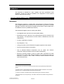
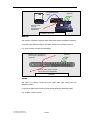
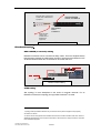
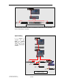
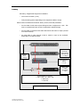
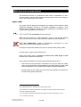
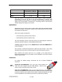
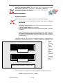
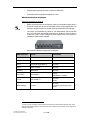
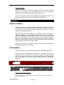
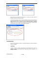
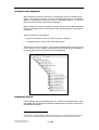
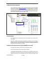
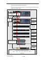
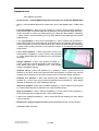
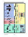
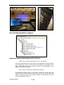
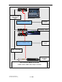
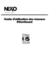
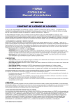
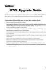
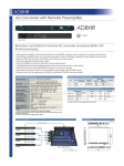
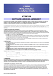
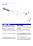
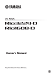
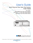
EtherSound networks Overview TABLE OF CONTENTS INTRODUCTION 3 EXPLANATION OF THE TECHNOLOGY 3 INTRODUCTION ........................................................................................................................................ 3 THE ETHERSOUND FRAME ...................................................................................................................... 4 ETHERSOUND TERMINOLOGY ................................................................................................................. 4 ETHERSOUND TOPOLOGY ........................................................................................................................ 7 UNIDIRECTIONAL AND BIDIRECTIONAL ETHERSOUND .......................................................................... 9 LATENCY ................................................................................................................................................ 11 NEXO RULES AND RECOMMENDATIONS 12 COPPER CABLES ..................................................................................................................................... 12 OPTICAL FIBRES..................................................................................................................................... 13 CONNECTORS ......................................................................................................................................... 13 INTERCONNECTION COMPONENTS ........................................................................................................ 14 REDUNDANCY 17 EQUIPMENT REDUNDANCY .................................................................................................................... 17 CABLE REDUNDANCY ............................................................................................................................. 17 CONTROLLING ETHERSOUND NETWORKS 19 ADVANTAGES OF NETWORKS ................................................................................................................ 19 SERVICE AND CONTROL APPLICATION .................................................................................................. 19 TUNNELLING FACILITY .......................................................................................................................... 20 BASIC CONCEPTS FOR USING ETHERSOUND MONITOR ........................................................................ 21 CASE STUDY NO. 1: CONCERT HALL 23 EQUIPMENT USED................................................................................................................................... 23 DESCRIPTION OF THE EQUIPMENT ........................................................................................................ 25 DEFINING THE DIRECTION ..................................................................................................................... 25 ROUTING ETHERSOUND EQUIPMENT .................................................................................................... 26 CREATION OF GROUPS ........................................................................................................................... 33 CONFIGURATION OF NEXO EQUIPMENT ................................................................................................ 34 TECHNICAL OPTIONS ............................................................................................................................. 34 CALCULATION OF THE LATENCY BETWEEN THE FIRST AD8HR AND A FRONT NX ............................ 34 CASE STUDY NO. 2: THEATRE 36 DESCRIPTION ......................................................................................................................................... 36 EQUIPMENT USED................................................................................................................................... 37 PLAN OF THE ETHERSOUND MONITOR EQUIPMENT ............................................................................ 40 QUESTIONS & ANSWERS WITH ARI MANNINEN FROM HEDCOM ......................................................... 40 TECHNICAL OPTIONS ............................................................................................................................. 41 LATENCY CALCULATION BETWEEN THE CONSOLE AND THE FRONT SPEAKER NXS ............................ 41 CASE STUDY NO. 3: FITTING OUT A STADIUM 43 DESCRIPTION ......................................................................................................................................... 43 EQUIPMENT USED................................................................................................................................... 43 PLAN OF THE ETHERSOUND MONITOR EQUIPMENT ............................................................................ 43 TECHNICAL OPTIONS ............................................................................................................................. 45 CALCULATION OF LATENCY BETWEEN THE CONSOLE AND WEST 1 BAY ............................................. 45 NOTES 46 NXTENSION USER MANUAL DOCUMENT REVISION 011004 PAGE 2 Introduction This document is intended for users, installers and other professional audio specialists. Its aim is to ease the installation and configuration of sound systems based on EtherSound technology. Explanation of the technology Introduction The EtherSound network is a digital audio network based on Ethernet technology which enables digitised audio channels and command data to be carried on a simple dedicated1 local area network (LAN) compatible with full-duplex2 Ethernet IEEE 802.3 at 100Mbits/s minimum (100 Mbits/s per direction). The EtherSound Digigram protocol3 used by Nexo allows: o 2x64 digitised audio channels to be carried (24bits-48kHz). o Bi-directional use (64 channels in one network direction and 64 channels in the other direction - an improvement on the first version of EtherSound, which was unidirectional). o A known, small latency (125µsec). o Very little jitter4 (< 1ns). o Listing and remote control of EtherSound equipment present on the network. o Synchronous transmission of information. o Use of standard Ethernet components such as cables and switches. (CAUTION: certain precautions have to be taken nevertheless!) o Maximum connection length of 100m for copper cable. (CAUTION: This value depends on the quality of the cable and whether or not connectors are used.) For distances in excess of 100m, media converters, Ethernet switches and fibre optics should be used. 1 Data which does not conform to the EtherSound protocol should not be passed along the EtherSound network. 2 Full duplex mode is an optional EtherSound working mode which enables simultaneous communication between two units. It provides separate transmit and receive data paths. 3 A protocol is a collection of pre-defined rules precisely describing how a transmission achieved. 4 Jitter is the variation of the clock pulse edge. This variation causes harmonic distortion during A/D and D/A conversions. NXTENSION USER MANUAL DOCUMENT REVISION 011004 PAGE 3 Digital audio networks based on Ethernet offer: o The advantages of digital audio (quality which is dependent only on conversion, robust transmission, easy processing, low cost) combined with those of Ethernet networks (easy network management, expansion capability, reliability of network). o The elimination of intermediate A/D and D/A conversions (improving inherent latency times). The EtherSound frame Since EtherSound networks are compatible with Ethernet network components, data sent by EtherSound equipment must adhere to certain rules. These data are transmitted in the form of fixed frames3 (see figure 1.2.a). These frames are sent at a frequency of 48kHz, which enables the analogue/digital and digital/analogue converters to synchronise on the beginning of this frame (giving very little jitter). 236 fixed bytes EtherSound terminology … FCS Audio Data channel 64 Audio Data channel 2 Audio Data channel 1 Audio Header Command PRIMARY MASTER Command Header EtherSound Header Ethernet header Preamble In the EtherSound context, the terms “primary master”, “master”, “master slave” and “slave” take on particular significance. The primary master is the first piece of equipment in the EtherSound network. Its output alone is connected to another item of EtherSound equipment. This is the first network component, which writes the audio data in the1 24-bit EtherSound sampleframe: it generates the clock. If the network is controlled by a computer, the Ethernet port of the computer should be connected to the input of the primary master with a crossed Ethernet cable.ETHERSOUND frame EtherSound terminology In the context of EtherSound, the terms “Primary master”, “Master”, “Master/Slave” and “Slave” take on particular meanings. PRIMARY MASTER The primary master is the first piece of equipment in the EtherSound network. Its output alone is connected to another item of EtherSound equipment. This is the first network component which writes the audio data in the EtherSound frame: it generates the clock. If the network is controlled by a computer, the Ethernet port of the computer should be connected to the input of the primary master with a crossed Ethernet cable. 3 A frame is a data sequence which can be read by components in the network. NXTENSION USER MANUAL DOCUMENT REVISION 011004 PAGE 4 Crossed Ethernet cable Audio IN Ethernet cable, going to another item of equipment PRIMARY MASTER MASTER The master is a network component which writes audio data to the EtherSound frame. It converts audio signals (analogue, AES-EBU, Adat) into the EtherSound format. E.g.: Input converter, microphone preamplifier Ethernet cable, coming from another item of EtherSound equipment Audio IN Ethernet cable, going to another item of EtherSound equipment MASTER SLAVE The slave is a network component which reads audio data coming from the EtherSound frame. It converts the EtherSound format into audio signals (analogue, AES-EBU, Adat). E.g.: amplifier, output converter NXTENSION USER MANUAL DOCUMENT REVISION 011004 PAGE 5 Ethernet cable, coming from another item of EtherSound equipment Ethernet cable, going to another item of EtherSound equipment Audio SLAVE MASTER / SLAVE The master/slave is a network component which combines the functions of master and slave. Hence it can write and read audio data to/from the EtherSound frame. E.g.: console, matrix, processor, effects Ethernet cable, coming from another item of EtherSound equipment Ethernet cable, going to another item of EtherSound equipment Audio MASTER SLAVE NXTENSION USER MANUAL DOCUMENT REVISION 011004 Audio IN PAGE 6 Ethernet cable, coming from another item of EtherSound equipment UNPROCESSED AUDIO CHANNELS PROCESSED AUDIO CHANNELS Ethernet cable, coming from another item of EtherSound equipment MASTER SLAVE EtherSound topology1 DAISY-CHAIN (or cascade) cabling EtherSound networks can be connected as daisy chains. This is the simplest and the least expensive method: the cable leaves one item of equipment via its Ethercon OUT socket and enters another item via its Ethercon IN socket, and so on. DAISY-CHAIN cabling STAR cabling Star topology is more widespread in the world of computer networks. For an EtherSound network, this topology is only possible if switches2 are used. 1 Topology makes it possible to define the way in which the various pieces of equipment are physically connected in a network. 2 A switch is an item of equipment which enables various items to be interconnected to each other. When an addressed message enters one of the ports of the switch, it will be sent to the output port which is connected to the destination equipment. NXTENSION USER MANUAL DOCUMENT REVISION 011004 PAGE 7 STAR cabling CAUTION!: At the output of a switch, the EtherSound audio flow can only go further down (unidirectional) - see below. Hybrid cabling It is possible to combine the two types of cabling described above in order to form a more complex EtherSound network. HYBRID cabling NXTENSION USER MANUAL DOCUMENT REVISION 011004 PAGE 8 Unidirectional and bidirectional EtherSound UNIDIRECTIONAL mode In unidirectional mode, the equipment which is further down the chain will only be able to read the audio data written by equipment further up (descending audio flow). upstream downstream Unidirectional BIDIRECTIONAL mode In bidirectional mode, equipment further down the chain can read and write audio data to/from equipment situated further up the chain. The EtherSound frame can be bidirectional in such a case in the daisy-chain part of the network, provided that there are no switches further up the chain. (It may be possible to get around this in the case of an advanced switch using VLAN management.) upstream downstream Bidirectional The EtherSound frame goes down the network and can go back up the chain starting from an item of equipment for which the “loopback” function is activated. Loopback takes place at the layer of the module furthest up the chain having an active loopback function. NXTENSION USER MANUAL DOCUMENT REVISION 011004 PAGE 9 Equipment connected further down the chain than the item for which the “loopback” function is activated nevertheless receives the upstream frame which it emits. upstream LOOPBACK downstream Bidirectional / loopback Control data are systematically bidirectional, whatever the topology of the network and whether or not a switch is present. NXTENSION USER MANUAL DOCUMENT REVISION 011004 PAGE 10 Latency The latency of digital audio equipment is related to: o A/D or D/A conversion (~1ms) o DSP processing (varies, depending on the equipment, NX242 = 84µs) Where used on an EtherSound network, latency is short, fixed and predictable: o the time taken for the frame to pass through an item of equipment is 1.4µs. This time is cumulative each time an item of equipment is passed through. o the time taken to read and write audio data from/to the frame is 125µs (counted once in the network) o the time taken to pass through a level 2 switch is 21µs (to be confirmed, depending on the type of switch) Pass through EtherSound Component + 1,25µs Read / write 125 µs Pass through switch + 21 µs Read / write + 125µs, processing + 84µs Overall latency of system = 125 + 1.25 + 21 + 84 + 125 = 356.25 µs = 0.357 ms Latency calculation NXTENSION USER MANUAL DOCUMENT REVISION 011004 PAGE 11 NEXO rules and recommendations The EtherSound network is a professional audio network; nevertheless it is still a computer network. Certain habits relating to analogue practice have to be changed in order to take full advantage of the network. Copper cables The cables used for EtherSound equipment are category CAT5e Ethernet cables (1Gbits/sec bandwidth), category 6 (10 Gbits/sec bandwidth) or category 7 (new standard being developed). Category 5 cables (100Mbits/sec bandwidth) may be considered but will rapidly become obsolete. STP1 or SFTP2: RECOMMENDED for their robustness FTP3: Not recommended for mobile applications: there is a risk that the shielding screen will split when the cable is used intensively. Suitable for fixed installations. UTP4: NOT COMPATIBLE: shielding is indispensable if equipment is to work properly and be free of electromagnetic interference. CAUTION!: Crossed cable between the control computer and the primary master No other types of copper cable should be used. NEXO recommends using a maximum connection-free cable length of 80m between items of EtherSound equipment. These cables are available in solid (horizontal) and flexible (patch) forms: o Solid cables offer less attenuation with distance but are more difficult to handle. They are recommended for fixed installations with cables passing through walls and for long distances. They are difficult to handle for temporary installations. o Flexible cables are the easiest to use but are less acceptable for long distances because of their greater attenuation. 1 STP: ShieldedTwisted Pair: twisted pair with a braided copper sheath 2 SFTP: Shielded Foil Twisted Pair: twisted pair with shielding composed of a plastic-coated aluminium screen and a braided copper sheath. 3 FTP: Foil Twisted Pair: twisted pair with shielding composed of a plastic-coated aluminium screen 4 UTP: Unshielded Twisted Pair NXTENSION USER MANUAL DOCUMENT REVISION 011004 PAGE 12 o Horizontal cable attenuation (dB/m) Flexible cable attenuation (dB/m) CAT5e 0.22 0.32 CAT7 0.19 0.28 Given the variation in specification for the various makes of cables, disturbances encountered on the site, the need to use non-recommended or unknown cable already installed and the presence of connections, NEXO strongly recommend that cables over 50m are tested. To achieve this, a monitoring screen in the ESmonitor software displays the integrity of connections. Optical fibres Optical fibres may be used in place of copper cables. Data are transmitted optically instead of electrically. The maximum distance with multimode fibres is 2km and with monomode more than 20 km. There are two types of optical fibre: o Monomode fibre (maximum distance 20km) o Multimode fibre (maximum distance 2km) The main advantage of fibres is their total immunity to electromagnetic interference, small bulk and ease of fitting in a fixed installation (blown fibre). “Ordinary” fibres are fragile and thus EMPHATICALLY NOT RECOMMENDED for mobile installations. At the moment, no EtherSound equipment is fitted with optical sockets. Hence using optical fibres involves media converters (copper to optical and optical to copper). Many switches have optical ports; thus it is possible to use optical fibres to interconnect switches but this only applies to fixed installations since these switches require “ordinary” fibres. Connectors For mobile use, NEXO strongly recommend the use of Neutrik ETHERCON connectors. ETHERCON RECOMMENDED: They give good contact between the metal case of the equipment and the cable shielding. Above all, they ensure a robust connection equal to that of XLRs. RJ45 NOT RECOMMENDED: They are very fragile (the plug is only held in the socket by a tiny plastic flap). Contact between the metal case and the cable sheathing is insecure. However, they remain the only solution if advanced switches are used. For fixed installations, RJ45 cables may be used if not subjected to handling. NXTENSION USER MANUAL DOCUMENT REVISION 011004 PAGE 13 Unshielded RJ45 PROHIBITED: The NX242 is an item of equipment with certified electromagnetic performance. The use of an unshielded connector will invalidate the certification and expose the user to problems arising from electromagnetic interference or emission. Interconnection components Analogue techniques Certain practices common to analogue working are prohibited for networks: o A single cable may not be physically connected to two devices. Y-splitting PROHIBITED o Connecting two network cables together reduces their theoretical maximum overall length by 20 metres!!! ► Avoid CONNECTIONS as far as possible. ► Sockets brought out to the front of bays should be prohibited and replaced by switches. o Network cables require more care than analogue cables during setting up. An electrical continuity test alone is not enough: it has to be monitored in use via the Connection Manager module of the EtherSound Monitor software (Properties page). Technology based on real time such as EtherSound allows no compromises, by contrast with computer data transfer. In computing, data is sent repeatedly until it arrives intact, whereas in an audio network, bad transmiss Defective linkage ion means loss of informatio n. (Informati on is only sent Good linkage once.) EtherSound Monitor display of linkage quality In every case above, a computer is used which will perform the following functions: o Splitting the signal (in place of the Y-splitter) NXTENSION USER MANUAL DOCUMENT REVISION 011004 PAGE 14 o Amplifying the signal (in the case of maximum distances) o Connecting items of equipment together in a rack EtherSound network techniques Switches1 working on layer 2 o NEXO recommend the use of switches working on the data link layer (layer 2 of the OSI model) also known as the Media Access Control (MAC) layer. On this layer, analysis of frames is simple and thus transmission is fast (21µs). o The switch recommended by NEXO is the Wagnertools switch ESU-205 since it is one of the few switches with Ethercon sockets. It works on layer 2 of the OSI model. It also manages several supplies with hard contacts to indicate the state of these supplies. o Other switches tested and approved by Digigram Manufacturer Model Functions Net Gear 16-10/100 16 ports LinkSys EG0801 8 ports 3Com 3C16464B SuperStack 3 12 ports 3Com Office Connect 16 ports PLANET FNSW 2401 24 ports Level One GSW-08801T 8 ports 100Mbits/s or 1Gbit/s D-Link DES-1218R 16 16 ports VLAN Allied Telesyn AT-8024 24 ports 2 “ordinary” fibre optic ports VLAN 1 A switch is an item of equipment which enables various items to be interconnected with each other. When an addressed message enters one of the ports of the switch, it will be sent to the output port connected to the destination equipment. NXTENSION USER MANUAL DOCUMENT REVISION 011004 PAGE 15 Hubs1 Hubs should not be used on EtherSound networks WIFI (for the audio frame) The bandwidth of the current WIFI protocol is 54Mbits/s (802.11g) or 11 Mbits/s (802.11b). EtherSound frames containing audio data cannot therefore circulate on such a linkage (100Mbits/s bandwidth for an EtherSound frame) WIFI (for control / monitoring) There nevertheless remains the possibility of using a WIFI connection between a control computer and equipment connected to the primary master (see below). WIFI router with Auvitran EtherSound service installed Linkage The reliability of a WIFI connection depends on the area where it is situated. Control computer with EtherSound Monitor application installed Primary Master Example of WIFI control of an EtherSound network The reliability of a WIFI linkage depends on where it is situated: a big WIFI network close to the installation may cause problems. 1 A hub is a very basic interconnection device. Each port of the hub sends out all the information coming from the other ports. By contrast with a switch, there is no address management. This device might be imagined to serve a unidirectional Ethersound network equivalent to a Y-splitter but it should not be forgotten that information goes back up to the computer connected to the primary master. Hubs cannot therefore be used in EtherSound networks. NXTENSION USER MANUAL DOCUMENT REVISION 011004 PAGE 16 High-level router2 A high-level router may be connected to the primary master. Control of the network is carried out by a computer which communicates with this router. The connection between the computer and the router can be WIFI, Ethernet, etc. As with WIFI, this type of router is only acceptable for the linkage between the PC and the primary master (control) and not in the EtherSound network itself. Redundancy Equipment redundancy The only situation in which reliability problems differ between a traditional system and an EtherSound system is the particular case of daisy-chain cabling. In this mode, if one unit fails, it causes all the other equipment further down to fail. Hence, for a critical application, star cabling is preferred. With star cabling, the risk of breakdown is no greater than that encountered in a traditional installation. To make an EtherSound network secure, the same measures apply as for a traditional network (standby equipment with the facility to switch rapidly from one to the other). It is even easier to switch from a broken-down piece of equipment to the standby, thanks to the extensive patch facilities available in ESmonitor. Detecting faulty equipment is also made easier thanks to the real-time automatic listing function in the ESmonitor software. Certain switches (such as the Wagner Tools ESU-205) have multiple power supplies with hard contact alarms in case of failure. Cable redundancy NEXO recommends using an AUVITRAN AVRed-ES for redundant cabling circuits. AVRed-ES secures an EtherSound connection with 2 redundant links A/B and automatic real time measurement of communication quality and 4 samples latency switch on the better link. AVRed-ES is running in pair with another AVDRed-ES for very low propagation delay or after a standard Ethernet switch for cost sensitive installation. Active A A B B In/Out Rx In Out Tx Link Activity 2 Status Mode Power A high-level router makes it possible to carry out a protocol conversion if the service which performs this conversion is installed in it. NXTENSION USER MANUAL DOCUMENT REVISION 011004 PAGE 17 This product has the following features: o Automatic selection of the better connection: A or B. o Alerts on hard contact. o Fully-configurable by the EtherSound network o Two modes of working In A Double AVRed-ESs for a known and minimum latency time (4µs) Switch + AVRed-ES = 22µs+2µs latency Out Switch B B B In A In Out NXTENSION USER MANUAL DOCUMENT REVISION 011004 PAGE 18 A Out Controlling EtherSound networks Advantages of networks One of the main advantages of a network is its ability to be administered, i.e. to be controlled by a computer. In relation to an audio network, each technology allows space for the transmission of data other than audio data. Items of equipment connected to the network can send information related to their role (control, monitoring) and the user can send them commands. But often, each constructor develops their own administration system. The user has to juggle with as many different administration programs as there are items of equipment in stock. The great strength of EtherSound is the federation of licensed producers grouped around the Auvitran company which is developing a free, fast administration program called the EtherSound Monitor (which runs under Windows 2000 and XP). Hence it is possible, for example, to run an NX242 fitted with a Nexo ES4 Nxtension card and a Digigram or NetCira input converter with the same program, making the user’s job far easier. The EtherSound Monitor program, together with the user manual and installation manual may be downloaded from the Auvitran site at www.auvitran.com. Service and control application Explanation In monitoring an EtherSound network, it is necessary to distinguish between the service and the application. The control application is, for example, EtherSound Monitor. It consists of a graphical interface, enabling the user to control the network. The commands which the user chooses are then sent to the service which is going to shape them up and send them to the primary master. Sending command information to the EtherSound network is thus done in two stages. This division of tasks enables the application and the service to be split between two machines. Local service and distant service The Auvitran Service Control Panel is the service for the EtherSound Monitor. The service has to be activated in order that the application can communicate with the network. NXTENSION USER MANUAL DOCUMENT REVISION 011004 PAGE 19 Service should be activated on the computer (or a router in the case of WIFI, for example) connected to the primary master. The ESmonitor application which controls the network can then be activated either on the same computer (local service) or on another computer connected to the network (distant service). Thus it is sufficient to tell the EtherSound Monitor application installed on the control computer the IP address of the computer or router which is connected to the primary master of the EtherSound network. Tunnelling facility Auvitran has expanded the capacity of command channels by making it possible to carry out “tunnelling”. Tunnelling Tunnelling consists of creating a virtual linkage in the EtherSound link. Hence it is possible to circulate other data apart from audio and command channels in an EtherSound linkage. NXTENSION USER MANUAL DOCUMENT REVISION 011004 PAGE 20 Midi tunnelling Auvitran has developed this facility in order to circulate midi1 data from StudioManager (control software for the latest Yamaha consoles). It is thus possible to send commands to a Yamaha console from the EtherSound network control computer. If this computer uses a WIFI link with the router connected to the primary master, the console will be controlled via WIFI. RS232 tunnelling RS232 tunnelling retains the principle of midi tunnelling. Instead of passing midi data through the EtherSound frame, RS232 data is involved. Auvitran has developed control software for Yamaha AD8HR preamplifiers. The commands are transmitted using RS232 tunnelling. It should be noted that the tunnelling technique is only possible with Auvitran cards but it remains transparent with respect to other equipment connected to the network. Basic concepts for using EtherSound Monitor Before getting to grips with the software, it is indispensable to understand the philosophy of routing audio channels in EtherSound Monitor software. Channel routing is found in the I/O patch page. There are two tables there (if the equipment is able to be master/slave): o Down Out<ES (or Up ES>Out in the bidirectional case) o Down In>ES (or Down ES<IN in the bidirectional case) 1 Midi (Musical Instrument Digital Interface) is a standard for communication between musical instruments, computers, audio equipment, etc. NXTENSION USER MANUAL DOCUMENT REVISION 011004 PAGE 21 o EtherSound ES = frame EtherSound Out = output of EtherSound card built into the equipment In = input of EtherSound card built into the equipment EtherSound card In Audio OUT Audio IN EQUIPMENT Principal of routing NXTENSION USER MANUAL DOCUMENT REVISION 011004 Out PAGE 22 Case Study No. 1: CONCERT HALL Equipment used The installation comprises: o Front Of House (F.O.H) console: 1 Yamaha PM5D fitted with 2 Auvitran AVY 16-ES cards (FRONT PM5D Slot 1 / FRONT PM5D Slot 2) o Monitoring console: 1 Yamaha PM5D fitted with 2 Auvitran AVY 16-ES cards (REAR PM5D Slot 1 / REAR PM5D Slot 2) o Microphone preamplifiers: 4 Yamaha AD8HRs fitted with Auvitran AVkit cards (AD8HR 1-8 / 9-16 / 17-24 / 25-32) o Front left speakers: 1 Nexo CD18 sub amplified by 1 Camco Vortex 6 and processed by 1 Nexo NX242 Digital TDcontroller fitted with an NXtension-ES4 card (FRONT CD18 NX). 1 cluster composed of 6 Nexo GeoT 4805 speakers and 2 Nexo GeoT 2815 speakers, amplified by 3 Camco Vortex 6s and processed by 1 Nexo NX242 Digital TDcontroller fitted with an NXtension-ES4 card (FRONT stage right NX) o Front right speakers: 1 Nexo CD18 sub amplified by 1 Camco Vortex 6 and processed by the same NX242 as the sub for the left front speakers. 1 cluster composed of 6 Nexo GeoT 4805 speakers and 2 Nexo GeoT 2815 speakers, amplified by 3 Camco Vortex 6s and processed by 1 Nexo NX242 fitted with an NXtension-ES4 card (FRONT stage left NX) o Rear speakers: 12 Nexo PS 15 speakers amplified by 6 Camco Vortex 6s and processed by 3 Nexo NX242s fitted with an NXtension-ES4 card (AUX 1-4 / AUX 5-8 / AUX 9-12 NX) o Live recording console: 1 Yamaha DM2000 fitted with 2 Auvitran AVY 16-ES cards (DM2000 REC Slot 1 / DM2000 REC Slot 2) o Radio broadcast console: 1 Yamaha DM2000 fitted with 2 Auvitran AVY 16-ES cards. (DM2000 RADIO Slot 1 / DM2000 RADIO Slot 2) o 5 WagnerTools ESU205 switches + computer running under Windows XP. NXTENSION USER MANUAL DOCUMENT REVISION 011004 PAGE 23 NXTENSION USER MANUAL DOCUMENT REVISION 011004 PAGE 24 Description of the equipment When EtherSound network equipment is connected and service is activated (Edit > Engine Control Panel > Service > Turn On), the MAC addresses1 of the equipment appear in the EtherSound Networks section of EtherSound Monitor. In the Tree window, the tree structure of the network is displayed. Before starting the routing, the equipment needs to be renamed as MAC addresses are fairly meaningless from the user’s point of view. Remaining with the Tree page for the moment: There are various ways of doing this: o Right click on the item concerned > Device functions > Rename o Properties window > enter a name in the Name section Switches are not shown as images. Their presence is detected when equipment is set out in a column. For the network, several interconnected switches are considered to be a single switch (even though their latencies add together). Defining the direction In this installation, the Primary Master is the AVY 16-ES card inserted into Slot 1 of the front PM5D card. The EtherSound network is bidirectional from the front console up to the AD8HR preamplifiers. 1 A MAC address or physical address is written on the network card. It is unique worldwide and is decided by the constructor. This address enables items of EtherSound equipment to communicate with each other. NXTENSION USER MANUAL DOCUMENT REVISION 011004 PAGE 25 If the upper part of the network (below all the switches and connected in a daisy chain) is required to be bidirectional, the item of equipment furthest below the bidirectional linkage should be selected. In our example, this is the AD8HR 25-32. Then go into the Properties window and click on Loopback. The green symbols signifying bidirectional mode then appear: Routing EtherSound equipment We will explain how equipment is configured by following the audio pathway. So we start with the first AD8HR in the chain and not with the Primary Master. We are on the I/O Patch page. AD8HR 1-8 This micro preamplifier writes to the first 8 channels of the EtherSound frame. It sends the data further down the network (Down In>ES table). Signals entering the preamplifier may be named by clicking in the Alias box corresponding to the preamplifier input. To route the signals entering the EtherSound frame channels: Left click Names of incoming signals Left click to send channels further down the network NXTENSION USER MANUAL DOCUMENT REVISION 011004 PAGE 26 AD8HR 9-16, 17-24 The steps are exactly the same for the other AD8HRs, except that the routing of signals entering the EtherSound channels is different for each preamplifier. AD8HR 25-32 The routing manoeuvres are the same as above. This is the item of equipment which marks the end of the bidirectional link, so its loopback box should be checked. Data will thus be sent further up the bidirectional linkage as well as further down the network. Loopback F.O.H. PM5D Slot 1 The front console retrieves the channels written to by the AD8HR preamplifiers (1 to 32), mixes them and sends out the mix on two EtherSound channels (Right 63 and Left 64) which go to the front speakers. As there are 32 channels to be read and the Auvitran AVY 16-ES card allows 16 channels to be written to or read, the console has to be fitted with two of these cards. NXTENSION USER MANUAL DOCUMENT REVISION 011004 PAGE 27 From the EtherSound point of view, the console reads channels which come from further down the network (Up ES>Out table). To route the channels coming from further down to the card outputs: right click. The two mixing output channels are written to in the frame which goes further down. Routing is carried out as for the AD8HRs. Right click to retrieve channels coming from further down the network Left click to send channels further down the network F.O.H. PM5D Slot 2 Same principle, except for reading channels 17 to 32, and no writing to the channels. NXTENSION USER MANUAL DOCUMENT REVISION 011004 PAGE 28 MONITORING PM5D Slots 1 and 2 The rear console retrieves the channels written to by the ES8 mic preamplifiers (1 to 32), does a balance to 12 Aux and sends these 12 Aux to 12 EtherSound channels (33 to 44) which go to the rear speakers. NX242 Front of House The front NX242s read all channels 63 (equipment processing the Right signal) or 64 (equipment processing the Left signal) of the EtherSound frame The NX242s for the subs read channels 63 and 64. NXTENSION USER MANUAL DOCUMENT REVISION 011004 PAGE 29 NX242 AUX (monitor) NX242 AUX 1-4 reads channels 33 to 36, NX242 5-8 reads channels 37 to 40 and NX242 AUX 9-12 reads channels 41 to 44. Each of these NXs processes the signal for the corresponding speakers (rear 1 to 12). NXTENSION USER MANUAL DOCUMENT REVISION 011004 PAGE 30 REC and RADIO consoles These consoles only read channels coming from the AD8HR preamplifiers. The mixing which they do in no way affects the rest of the network (since they do not write anything on the EtherSound frame). NXTENSION USER MANUAL DOCUMENT REVISION 011004 PAGE 31 NXTENSION USER MANUAL DOCUMENT REVISION 011004 PAGE 32 Creation of groups With EtherSound Monitor it is possible to create groups. This can be very useful, particularly for “muting” several items of equipment. In this installation, two groups have been formed: one group for the front NX242s and another for the rear NX242s. To create a group: Group page > right click on the white area > Add Group > name the group. On the equipment Control page, a Group box will appear with buttons corresponding to the various groups. So, to allocate the selected item of equipment to a group, simply click on the button for the required group. Right click FOH group NXTENSION USER MANUAL DOCUMENT REVISION 011004 PAGE 33 Configuration of Nexo equipment The user manual for the NX242 section of EtherSound Monitor may be downloaded from the Nexo website at www.nexo-sa.com. We strongly advise you to read this document as a supplement. Each NX242 must be configured with the right setup. This setup varies according to the type of speakers plugged in at the rear of the amplifier connected to the NX242. To change the setup of an NX242: Control page > Set > select the combination of speakers used > Apply Change Setup Technical options This installation uses the bidirectional mode of EtherSound, which requires daisychain cabling. Daisy-chain cabling is practical and economical (in comparison with star cabling). However, it should be remembered that a failure in one component has repercussions throughout the chain. (See the paragraph on redundancy.) Equipment (cables and electronics) should be checked very carefully. Calculation of the latency between the first AD8HR and a front NX If we suppose that a PM5D console’s DSP processing takes 168µs, then the calculated latency in the diagram below is 0.850ms. It is generally accepted that delays of this order are of no consequence either for the front speakers or for those at the rear. It will shortly be possible to reset the items of equipment with respect to each other with a precision of 1/256 of the sample in order NXTENSION USER MANUAL DOCUMENT REVISION 011004 PAGE 34 to avoid any lag due to the latency of the network. It should be further noted that this latency is less than that which would have been obtained with analogue cabling. Read / write 125µs+ processing 168µs Read / write 125µs Transit time + 1.25 µs Transit time + 1.25 µs Transit time 1.25 + 1.25 = 2.5 µs both ways (bi-dir) Transit time + 2.5 µs Transit time + 2.5 µs Transit time + 2.5 µs Transit time + 21 µs Read / write 125µs + processing 168µs Transit time + 21 µs Processing + 84 µs Latency between AD8HR and front NX = 125x3 + 1.25x2 +Latency 2.5x4 + calculation 21x2 + 168x2 + 84 = 849.5 µs = 0.850 ms NXTENSION USER MANUAL DOCUMENT REVISION 011004 PAGE 35 Case Study No. 2: THEATRE Description The following installation is a NEXO sound system using EtherSound technology in the theatre of the Oulu Polytechnic school in Finland (http://www.oamk.fi/english/). The system was designed and installed by the Hedcom company under the direction of Mr Ari Manninen. The sound system in this theatre is type 5.1 (Front speakers Left, Right and Centre; and speakers mounted in the auditorium). To cope with the problems posed by theatrical productions, speakers are mounted on the stage. Audio processing for the sound system is done by a Yamaha DME64 digital matrix. The linkages between the audio sources and the sound desk are either analogue or HF. The audio sources are mixed in a Yamaha DM2000 console fitted with an Auvitran AVY16-ES card. The 16 channels written to by the console are then sent to a Yamaha DME64 matrix fitted with two Auvitran AVY16-ES cards. The output of the first EtherSound card of the DME64 is sent to a switch connected to the Nexo NX242 Digital TDcontroller speaker processors fitted with EtherSound Nxtension-ES4 extension cards. The signal is then sent in analogue form to the various amplifiers. These amplifiers feed the speakers situated in the auditorium. An EtherSound / Netcira MS8-SO2 8-channel analogue conversion module is also connected to this switch. The output of the second EtherSound card of the DME64 is daisy-chained to the processors of the speakers situated on the stage. An EtherSound / Netcira MS8-SO2 8-channel analogue conversion module is at the end of the chain. It should be noted that the computer controls the equipment in the EtherSound network and other equipment (HF receiver, dedicated systems, etc.). The various commands coexist on the switch which is located between the computer and the primary master. NXTENSION USER MANUAL DOCUMENT REVISION 011004 PAGE 36 Equipment used The installation comprises: o Sound console: 1 Yamaha DM2000 fitted with an Auvitran AVY 16-ES card (DM2000 Slot) o Matrix: 1 Yamaha DME64 fitted with 2 Auvitran AVY 16-ES cards (DME64 Slot 1 / DME64 Slot 2) o F.O.H. left speakers: 1 Nexo CD12 sub amplified by 1 Camco Vortex 6 and processed by 1 Nexo NX242 Digital TDcontroller fitted with an NXtension-ES4 card (FRONT stage right NX), 1 cluster composed of 5 Nexo Geo S805 speakers and 1 Nexo Geo S830 speaker, amplified by 1 Camco Vortex 6 and processed by the same Nexo NX242 as the stage-right Sub (FRONT stage right NX) o F.O.H. right speakers: 1 Nexo CD12 sub amplified by 1 Camco Vortex 6 and processed by 1 Nexo NX242 Digital TDcontroller fitted with an NXtension-ES4 card (FRONT stage left NX); 1 cluster composed of 5 Nexo Geo S805 speakers; and 1 Nexo Geo S830 speaker, amplified by 1 Camco Vortex 6 and processed by the same Nexo NX242 as the stage-left Sub (FRONT stage left NX) o F.O.H. centre speakers: 1 cluster composed of 3 Nexo Geo S830 speakers, amplified by 1 Camco Vortex 6 and processed by 1 Nexo NX242 fitted with an NXtension ES4 card (FRONT centre NX) o Delayed speakers: 2 Nexo PS8 speakers amplified by 1 Camco Vortex Q3 (4-channel amplification) and processed by 1 Nexo NX242 fitted with an NXtension ES4 card (FRONT booster / AUDIENCE side NX) o Audience side fill: 4 Nexo PS8 speakers (2 x 2 speakers in series = upper and lower left speakers on one amp. channel and upper and lower right speakers on another amp. channel) amplified and processed by the remaining channels of the front booster speaker equipment o Audience rear speakers: 4 Nexo PS8 speakers (left stalls/balcony, right stalls/balcony) amplified by 1 Camco Vortex Q3 (4-channel amplification) and processed by 1 Nexo NX242 fitted with an Nxtension ES4 card (AUDIENCE rear NX) o Stage front speakers: 2 Nexo PS10 speakers amplified by 1 Camco Vortex 6 and processed by 1 Nexo NX242 fitted with an NXtension ES4 card (STAGE front NX) o Stage rear speakers: 1 Nexo LS500 sub amplified by 1 Camco Vortex 6 and processed by 1 Nexo NX242 fitted with an NXtension ES4 card (STAGE rear NX) o 2 Nexo PS10 speakers amplified by 1 Camco Vortex Q6 and processed by the same NX242 as the LS 500 sub. o EtherSound > analogue output converter: Netcira MS8 fitted with SO2 card (8 channels) o 3 switches: SMC EZ1024DT NXTENSION USER MANUAL DOCUMENT REVISION 011004 PAGE 37 NXTENSION USER MANUAL DOCUMENT REVISION 011004 PAGE 38 Front Left Front Centre Stage Rear (hidden) Stage Front (hidden) Front booster Audience Rear Audience sides NXTENSION USER MANUAL DOCUMENT REVISION 011004 PAGE 39 Front Right Plan of the EtherSound Monitor equipment Questions & Answers with Ari Manninen from Hedcom - What was the basic specification for the installation? The person responsible for the school’s audio (Jussi Lappalainen) wanted the theatre to be equipped with a type 5.1 sound system in the auditorium, with speakers on the stage. Jussi wanted to be able to store the various control parameters for the equipment and rapidly recall them. - Why have you chosen an EtherSound network? The EtherSound solution came to mind when I studied the project plans. The equipment is more expensive but the cost of cabling is very low. The use of CAT5e cables, the facilities for audio routing and the savings in time and labour which this network offers tipped the balance. NXTENSION USER MANUAL DOCUMENT REVISION 011004 PAGE 40 - Was the network topology already mentioned in the initial specification? The first generation design was analogue, based on the use of CAT5e cables to carry the analogue audio signal. When we decided to use an EtherSound network, the job was fairly simple because we had already specified the system for CAT5e analogue cabling. - Did you encounter any problems? For an audio technician who has never used a network in his life, configuring an IP address is still something new and intimidating. But with minimal introduction to and awareness of the rules to be followed, configuring the network was achieved without any problems. It’s true that, at the beginning, every smallest problem encountered seemed to be a disaster but it soon became clear that problems are easily surmountable, often being caused by poor handling. The network control software is clear and easily installed. Technical options This installation does not use EtherSound’s bidirectional mode and writing to audio channels in the EtherSound frame is only done from the control desk. Star cabling is used for the audience speakers, which need to be as secure as possible. This means, in addition, that even small time lags between the various speakers are avoided. Daisy-chain cabling is only used for the speakers on the stage. Furthermore, there is effective separation of the audience and stage speakers via the 2 DME64 cards. Latency calculation between the console and the front speaker NXs If the DSP processing time of a DME64 matrix is 168 µs, then the latency = 125x2 + 21x2 + 168x2 + 84 = 712 µs = 0.712 ms NXTENSION USER MANUAL DOCUMENT REVISION 011004 PAGE 41 Processing 168µs Read / write + 125µs Transit time + 21 µs Ethernet 100BaseT switch processing + 168µs Ethernet 100BaseT switch Transit time + 21 µs Read / write 125µs Processing + 84µs Latency between DM2000 and front NX = 125x2 + 21x2Latency + 168x2Calculation + 84 = 712 µs = 0.712 ms NXTENSION USER MANUAL DOCUMENT REVISION 011004 PAGE 42 Case Study No. 3: fitting out a STADIUM Description This system is a stadium installation with the speakers divided into zones. It is intended for amplifying music and speech. Each group of speakers is fed by equipment located in a bay situated near to connecting points. Each bay is fitted with a switch, three amplifiers and an NX242 Digital TDcontroller. Even though the cabling seems closely to resemble daisy-chain connection, it is in fact star connection. All the EtherSound equipment is connected to switches in order to ensure maximum network security. Equipment used The installation comprises: o Sound console: 1 Yamaha DM2000 fitted with 2 Auvitran AVY16ES cards (DM2000 Slot) o Speakers in each bay: 2 clusters of 6 Nexo Geo T2815 speakers amplified by 3 Camco Vortex 6s and processed by 1 Nexo NX242 Digital TDcontroller fitted with an NXtension-ES4 card (FRONT stage right NX) The installation comprises a total of 10 bays, giving 20 cluster connection points. Plan of the EtherSound Monitor equipment NXTENSION USER MANUAL DOCUMENT REVISION 011004 PAGE 43 NXTENSION USER MANUAL DOCUMENT REVISION 011004 PAGE 44 Technical options This is the most secure installation because it uses switches and star cabling fully. Calculation of latency between the console and West 1 bay Latency = 125 + 1.25 + 168 + 21x6 + 84 = 504.25 µs = 0.505 ms Transit time + 1.25 µs Processing 168µs Read / write +125µs Transit time + 21 µs Transit time + 21 µs Transit time + 21 µs Transit time + 21 µs Transit time + 21 µs Transit time + 21 µs Processing + 84µs Latency between DM2000 and front NX = 1.25 + 21x6 + 168 + 84 = 504.25 µs = 0.505 ms NXTENSION USER MANUAL DOCUMENT REVISION 011004 PAGE 45 NOTES NXTENSION USER MANUAL DOCUMENT REVISION 011004 PAGE 46 NXTENSION USER MANUAL DOCUMENT REVISION 011004 PAGE 47 France Nexo S.A. 154 allée des Erables ZAC des PARIS NORD II B.P. 50107 F-95950 Roissy CDG Cedex Tel: +33 1 48 63 19 14 Fax: +33 1 48 63 24 61 e-mail: [email protected] USA Nexo USA Inc. 2165 Francisco Boulevard Suite E2 San Rafael CA 94901 Tel: +1 415 482 6600 Fax: +1 415 482 6110 e-mail: [email protected] LatAM Nexo Latin America Hualfin 1054 1424 Capital Federal Argentina Tel +54 114 432 1911 Fax +54 114 431 1007 e-mail: [email protected] Far East Nexo Far East Pte. Ltd. No. 10 Ubi Crescent #02-35/36 Ubi Techpark (Lobby C) SINGAPORE 408564 Tel: +65 742 5660 Fax: +65 742 8050 e-mail: [email protected] www.nexo-sa.com