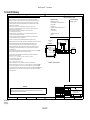
1
MACTek® Corporation BULLET® WirelessHART® Adapter Model 1101 Series User Manual MACTek BULLET ® - User Manual Table of Contents 1 INTRODUCTION ....................................................................................................................4 1.1 1.2 1.3 1.4 Overview ............................................................................................................................. 4 Basic Operation ................................................................................................................... 5 Typical Usage...................................................................................................................... 5 Power .................................................................................................................................. 5 1.4.1 1.4.2 1.4.3 2 CONFIGURATION .................................................................................................................8 2.1 2.2 2.3 3 Bench Top Hookup .............................................................................................................. 8 Device Configuration Using DTM ......................................................................................... 9 Device Configuration Using Device Description (DD) ......................................................... 21 INSTALLATION ...................................................................................................................23 3.1 3.2 Ordinary and Hazardous Locations .................................................................................... 23 BULLET installation to Field Device ................................................................................... 24 3.2.1 3.2.2 3.2.3 3.2.4 3.2.5 3.3 Field Device Mechanical Connection................................................................................... 24 Antenna Positioning ............................................................................................................ 25 Nameplate .......................................................................................................................... 25 Field Device Electrical Connection ...................................................................................... 25 Grounding ........................................................................................................................... 26 Installation Options ............................................................................................................ 26 3.3.1 3.3.2 3.3.3 3.3.4 3.3.5 3.3.6 3.3.7 4 Loop Powered Mode ............................................................................................................. 6 StepVolt™ Benefits ............................................................................................................... 7 Direct Powered Mode ............................................................................................................ 7 BULLET as a Standalone WirelessHART Router (Repeater)................................................. 27 BULLET with a 4-20mA Analog only Non-HART Field Device ............................................... 27 BULLET with a HART enabled Field Device ......................................................................... 27 BULLET with HART Field Devices in Multi-Drop Mode ......................................................... 28 BULLET with HART Field Devices in LOOP POWER Multi-Drop Mode ................................. 29 BULLET with HART Field Devices in DIRECT POWER Multi-Drop Mode .............................. 29 BULLET with a 4-20mA Field Device with Battery Powered Operation .................................. 30 DETAILED SETTINGS AND PARAMETER DEFINITIONS............................................................31 4.1 HART Dynamic Variables .................................................................................................. 31 4.1.1 4.1.2 4.1.3 4.1.4 4.1.5 4.1.6 4.1.7 4.1.8 4.1.9 4.2 4.3 4.4 Configure Power Mode (method) ......................................................................................... 31 Power Status ...................................................................................................................... 34 Join Device to Network (method) ......................................................................................... 35 Network ID .......................................................................................................................... 35 Join Key.............................................................................................................................. 35 Radio Output Power ............................................................................................................ 35 Scan for Devices (method) .................................................................................................. 37 4-20 mA Settings................................................................................................................. 37 PV Units ............................................................................................................................. 37 Automatic Burst Mode Configuration .................................................................................. 38 Factory Reset .................................................................................................................... 39 ALERTS ............................................................................................................................ 40 4.4.1 4.4.2 4.4.3 4.4.4 4.4.5 4.4.6 4.4.7 4.4.8 4.4.9 4.4.10 4.4.11 4.4.12 4.4.13 4.4.14 4.4.15 Active Alerts ........................................................................................................................ 40 Alert History ........................................................................................................................ 40 Clear Alert (method) ............................................................................................................ 40 Clear All Alerts (method)...................................................................................................... 40 ALERT – Direct Power Out of Range ................................................................................... 40 ALERT – Loop Power Out of Range..................................................................................... 40 ALERT – Temperature Out of Range ................................................................................... 41 ALERT – Power Mode Misconfigured................................................................................... 41 ALERT – Watchdog Reset ................................................................................................... 41 ALERT – Stack Overflow ................................................................................................... 42 ALERT – Duplicate HART Master Detected........................................................................ 42 ALERT – HART Devices Count Exceeded.......................................................................... 42 ALERT – HART Sub-Device Lost ....................................................................................... 43 ALERT – Burst Packets are Being Dropped ....................................................................... 43 ALERT – Field Device Power Control ................................................................................. 44 DM1101010UCA 30MAY2012 Copyright 2011 2 of 65 MACTek BULLET 4.4.16 4.4.17 4.4.18 4.4.19 4.4.20 4.4.21 4.4.22 4.4.23 4.5 ® - User Manual ALERT – Wireless Capacity Denied ................................................................................... 44 ALERT – Burst Message Configuration Issue ..................................................................... 44 ALERT – Wired Device in Burst Mode ................................................................................ 45 ALERT – BULLET Failed to Join the Network ..................................................................... 45 ALERT – Radio Malfunction............................................................................................... 45 ALERT – Variable Simulation............................................................................................. 46 ALERT – Field Device Cutoff Occurred .............................................................................. 46 ALERT – Low Battery ........................................................................................................ 46 HART Device Description (DD) TREE................................................................................ 47 5 MAINTENANCE ..................................................................................................................48 6 COMMISSIONING ................................................................................................................48 7 TROUBLESHOOTING...........................................................................................................49 8 PRODUCT INFORMATION ...................................................................................................50 9 SPECIFICATIONS................................................................................................................51 10 MECHANICAL ....................................................................................................................52 10.1.1 10.1.2 11 Dimensional Drawing......................................................................................................... 52 Enclosure.......................................................................................................................... 52 CERTIFICATIONS................................................................................................................53 11.1 11.2 European Directive Information ....................................................................................... 53 Telecommunication Compliance ..................................................................................... 53 11.2.1 11.2.2 11.3 11.4 FCC & IC .......................................................................................................................... 53 R&TTE.............................................................................................................................. 53 Ordinary Locations Certifications .................................................................................... 53 Hazardous Location Certificates ..................................................................................... 54 11.4.1 11.4.2 11.4.3 11.4.4 North America Certificates ................................................................................................. 54 European (ATEX) Certificates ............................................................................................ 56 IEC Certificates ................................................................................................................. 57 Required Certification Notices and Warnings...................................................................... 58 12 CONTROL DRAWING ..........................................................................................................60 13 RESOURCE GUIDE .............................................................................................................64 14 WARRANTY NOTICE...........................................................................................................65 DM1101010UCA 30MAY2012 Copyright 2011 3 of 65 MACTek BULLET ® - User Manual 1 Introduction 1.1 Overview The BULLET® enables new and existing wired HART field devices to communicate with host applications by means of WirelessHART® technology. The BULLET is permanently installed by attaching it directly into an available spare port of a HART field device, or by means of using a short, right angle elbow conduit connector. The BULLET can be inserted anywhere on the loop using a junction box or T-fitting. A wired HART field device retrofitted with a BULLET communicates its PV over the existing wire and simultaneously communicates the PV, SV, TV and QV as well as diagnostic and alarm data over the WirelessHART network to process control, asset management and other automation and engineering applications. The BULLET power configuration options are either existing loop power (scavenging) or local/direct power. The BULLET when loop powered saves users the long term cost of battery maintenance, replacement and disposal programs. The BULLET Local/Direct power option can be used when the field device is powered either by a DC power supply or an external battery/solar system. In the case of external battery power, the BULLET provides battery power management by cycling the field device power and taking periodic readings. Typical Use Cases Upgrade legacy wired HART or analog only field devices with WirelessHART communication capability to communicate the PV and other device data and diagnostic information to the gateway and ultimately the host application. Access HART device diagnostic information in HART-enabled devices in order to lower maintenance cost and improve plant operations Low cost wireless access to stranded monitoring and control data from improved o Asset management o Condition monitoring o Device diagnostics Connect up to 8 HART devices using only 1 BULLET – making WirelessHART more cost effective Remote IO applications of hard to reach locations Substitute for multiplexers or legacy DCS upgrade to HART-enabled I/O. External Battery powered wireless remote I/O data collection Low cost / low risk means to test and evaluate WirelessHART networks. Monitor / control of rotating and mobile equipment Features HART Registered fully HART compliant for communication reliability Universal connectivity – works with all registered HART devices Supports WirelessHART MESH and STAR network configurations Loop powered – no batteries or other power sources required Connects directly to HART field device and optionally anywhere on the 4-20 mA control loop MACTek patent pending StepVolt™ technology sets insertion voltage in steps from 1 to 2.5 volts to optimize the tradeoff between available loop power and Wireless communication bandwidth Direct Power option when local DC power is available: system power, external battery/solar system. In Direct Power mode, can switch field device on/off to take periodic readings to save power Internal 250 Ohm loop current sense and HART terminating resistor provided, configurable by WirelessHART command Multidrop support for up to 8 devices (maximum number depends on installation) 235 meters open air range (nominal) Rugged internal antenna design DM1101010UCA 30MAY2012 Copyright 2011 4 of 65 MACTek BULLET 1.2 ® - User Manual Basic Operation The BULLET® WirelessHART® Adapter allows new and existing wired-HART devices to be connected integrated into a WirelessHART network. This allows remote access to diagnostic data, digital process variables, and alarm data stored inside HART devices. The BULLET has both a Wireless interface to communicate with the WirelessHART network and a wired-HART interface to communicate to a traditional 4-20mA current loop device. The BULLET communicates as a wired-HART master to connected HART devices on the loop, and can transmit and receive HART data from these connected HART devices to the WirelessHART network. The BULLET also supports being configured like a wired-HART slave device, so traditional HART configuration tools (such as HART Field Communicators and PCs with HART modems) can be used to configure the BULLET. In WirelessHART terminology, any wired-HART devices that can be communicated with a WirelessHART Adapter are known as a sub-device. A single BULLET WirelessHART Adapter can support up to eight (8) wired-HART sub-devices. The WirelessHART Gateway maintains a list of all of the devices in the WirelessHART network, including sub-devices connected to WirelessHART Adapters. Host applications that communicate with the WirelessHART gateway communicates in-directly with the wired-HART sub-device through the WirelessHART Adapter. The WirelessHART gateway and WirelessHART Adapter transparently handle the message conversion between the Host application and wired-HART sub-device. WirelessHART supports publishing of data from devices to the WirelessHART Gateway on a periodic basis. This is called “burst mode” in HART terms, but is much more advanced than the “burst mode” traditionally supported by HART devices. Data can be burst based on an user defined update time or by a user specified triggered event; such as a process variable alarm. When the BULLET is configured in burst mode, it supports all of these advanced modes on behalf of any connected wired-HART sub-devices.. Burst mode is also very useful to publish device status data (such as malfunctions or alarms) to the Gateway on a periodic basis or immediately when a critical event occurs. 1.3 Typical Usage In most typical network configurations, the BULLET® will be used in conjunction with a wiredHART sub-device and configured to publish process data and device status data from the connected sub-device to the WirelessHART network on a user defined periodic basis (such as every 8 seconds or every minute, etc). The BULLET adds several features to make this typical usage mode very easy to configure, such as the Automatic Sub-Device detection and Automatic Burst mode configuration. 1.4 Power The BULLET WirelessHART Adapter has been designed to be extremely power efficient and flexible to allow for a wide variety of installation options. The BULLET can be installed to be powered by one of two sources either; 1) current loop denoted as LOOP POWER or 2) by a DC source denoted as DIRECT POWER. DM1101010UCA 30MAY2012 Copyright 2011 5 of 65 MACTek BULLET ® - User Manual 1.4.1 Loop Powered Mode The BULLET can be wired in series with devices on a 4-20mA loop and be powered from the loop. The BULLET utilizes MACTek’s patent pending StepVolt™ technology, to allow the user to set this insertion voltage drop between 1.0 – 2.5 Volts, in 0.5 Volt increments. StepVolt™ allows users to select the best insertion voltage drop for their application. The higher the voltage drop setting used, the more WirelessHART® messages the BULLET will be able to transmit and receive. In applications where there is very little voltage overhead in the loop, such as transmitters on very long cable runs or with IS barriers, StepVolt™ allows the selection of a low insertion voltage drop. However in typical applications there is adequate voltage overhead on the loop to allow for a higher insertion voltage drop from the BULLET. A concern with a loop powered WirelessHART Adapter is being able to operate under worst case low current conditions since very little power is available to be used by the Adapter.. The BULLET is designed to operate at the worst case operating conditions at all power settings and will respond to Wired or WirelessHART commands. The BULLET will operate as specified with reliable communications even under the following conditions: - Loop current of 3.2mA and 1.0V insertion voltage drop Temperature Extremes (-40C to +85C) Worst Case wired-HART communication on the loop. Constant wired-HART communication addressed to the Adapter and the Adapter responding to every command. Every WirelessHART timeslot filled and transmitting - NOTE On power-up, the insertion voltage drop will default to 1.0V until the Bullet has finished initialization. After initialization, the insertion voltage drop will change to the user specified value in the HART Device Description (DD). . The Bullet cannot control the loop current, if connected in loop-powered mode there must be device controlling the loop current, such as a 4-20mA transmitter WARNING IF THE BULLET HAS AN INTERNAL FAILURE AND STOP REGULATING TO THE SPECIFIED STEPVOLT™ VALUE, THE MAXIMUM INSERTION VOLTAGE DROP CAN RISE TO 4.935VDC. DM1101010UCA 30MAY2012 Copyright 2011 6 of 65 MACTek BULLET ® - User Manual 1.4.2 StepVolt™ Benefits The benefit to using a high StepVolt™ setting is that the BULLET will be able to support a much higher amount of WirelessHART® packets per second. Even if the particular device attached to the BULLET is configured for a very low update rate, being able to support a high amount of WirelessHART packets per second helps the overall WirelessHART network operation. WirelessHART is a mesh network – each node in the network will route messages on behalf of other nodes in the network. This is done to expand the overall range of the network and also for the data reliability of the network by forming multiple redundant paths. By setting the BULLET to a high StepVolt™ setting, more WirelessHART packets can be routed through the BULLET for other nodes in the network. Another consideration from a WirelessHART network standpoint is that many devices in a WirelessHART network are battery powered and all Wireless transmissions performed by these devices impact their battery life. The more WirelessHART devices that a battery powered node has to route messages for, the shorter its overall battery life. The BULLET is different – since it is loop powered it can support Wireless messages indefinitely without any concerns of battery life. By placing MACTek BULLET’s at key locations in a WirelessHART network, such as places that route messages for other WirelessHART nodes, this routing function can be offloaded from battery powered nodes to the BULLET and help to preserve their battery life of the battery powered nodes. StepVolt Setting 1.0 V 1.5 V 2.0V 2.5V WirelessHART Packets per Second 4.25 12.65 19.66 26.66 Note The value shown in WirelessHART Packets per second column is the value reported back in HART Command 777. Recommendation: Using the highest StepVolt™ setting possible will improve the overall WirelessHART network performance. 1.4.3 Direct Powered Mode The BULLET can be powered by an external DC power source such as; battery, solar panel or the DC power supply used to power the Field device. The DIRECT POWER voltage range is 7VDC to 32VDC. The DIRECT POWER connections are; 1) DIRECT POWER, black lead wire, to the positive potential (+) and 2) RETURN, white lead wire, to the negative terminal (-) of the external DC source. DM1101010UCA 30MAY2012 Copyright 2011 7 of 65 MACTek BULLET ® - User Manual 2 Configuration This section contains information on configuration that should be performed prior to installation of the BULLET in the field. Initial configuration is performed through the use of a HART Device Descriptor (DD) or Device Type Manager (DTM) for the BULLET over the wired-HART connection. Once connected to the WirelessHART network, configuration changes can be made using the DD/DTM over either the wired-HART interface or the WirelessHART interface. 2.1 Bench Top Hookup Tools Required 7-32VDC Power Supply HART modem WirelessHART network settings – Network ID an Join Key PC with DTM Frame application (PACTware) with the BULLET and Com DTMs installed Before configuring the bench top configuration test setup, adjust the DIRECT POWER source to a voltage between 7- 32VDC and turn off the DIRECT POWER source. Configure the BULLET, DIRECT POWER source and HART communicator per Figure 1. Referring to Figure 1, connect the DIRECT POWER source positive (+) terminal to the BULLET’s black lead wire and the DIRECT POWER source negative (-) terminal to the BULLET’s white lead wire. Connect HART modem to the BULLET. The BULLET’s HART signal connections are polarity independent. Connect the HART modem leads to the BULLET’s white lead-wire and yellow lead-wire. Ensure the Loop Power lead wire (RED) is not connected to any terminal of the DC power Source and or Earth Ground (Green/Yellow). Re-verify the test setup is configured per Figure 1 and then turn on the DIRECT POWER source, verify that the HART modem and PC or HART communicator is operating as expected and proceed to the following section – QUICK SETUP. Wire Color Green / Yellow Black Red White Yellow Ground Screw Description Internal Earth Ground Direct Power Loop Power Return HART External Earth Ground DM1101010UCA 30MAY2012 Copyright 2011 8 of 65 MACTek BULLET ® - User Manual FIGURE 1: BENCH TOP CONFIGURATION SETUP NOTE By default, the Bullet is at HART polling address 15. By default, all WirelessHART Adapters are configured as a primary HART master. The HART communicator used to configure the Bullet should be configured in Secondary HART master mode. WARNING THE BULLET CAN BE DAMAGED IF THE DIRECT POWER SOURCE IS GREATER THAN 32VDC 2.2 Device Configuration Using DTM This section utilizes the BULLET DTM and HART Communication DTM supplied on the product CD, and PACTware which is a no cost device configurator that utilizes FDT Technology. A DTM is an application that provides you configuration capabilities like an app on a Smartphone or a printer driver on your PC. You can download the PACTware application from one of the links at: http://www.pactware.com/en/downloads/pactware.html Install the BULLET DTM and HART Communications DTM supplied on the BULLET installation CD. Once PACTware is downloaded and installed, Start PACTware, update the device catalog and create a new project. DM1101010UCA 30MAY2012 Copyright 2011 9 of 65 MACTek BULLET ® - User Manual With “HOST PC” highlighted, click Add New Device Icon. FIGURE 2: PACTware ADD DEVICE TO NEW PROJECT From this window, select the HART Communication Device and click OK. FIGURE 3: PACTware DEVICE MENU DM1101010UCA 30MAY2012 Copyright 2011 10 of 65 MACTek BULLET ® - User Manual Right Click on the Communications DTM you just added and select Parameter form the menu. FIGURE 4: PACTware PARAMETER SELECTION Assign the correct com port for the HART Modem you are using. This example the Viator USB Modem is on COM3. FIGURE 5: COM PORT CONFIGURATION DM1101010UCA 30MAY2012 Copyright 2011 11 of 65 MACTek BULLET ® - User Manual Configure the other parameters: Preamble = 5 (some devices require a higher setting) Number of communication retries: = 3 Start Address = 0 End Address = 15 (the default polling address for the BULLET is 15) Select OK FIGURE 6 COM PORT CONFIGURATION DETAIL Project with COM DTM added. FIGURE 7: PACTware PROJECT WITH COM PORT CONFIGURE DM1101010UCA 30MAY2012 Copyright 2011 12 of 65 MACTek BULLET ® - User Manual With the COM DTM selected click the “Add Device Icon” then select the “BULLET HART DTM” form the Menu. And select OK. FIGURE 8: ADD BULLET DTM TO PACTware PROJECT Right click on the BULLET DTM and select “Additional functions / Communication” form the menu. FIGURE 9: SELECT COMMUNICATION DM1101010UCA 30MAY2012 Copyright 2011 13 of 65 MACTek BULLET ® - User Manual Configure the “Polling Address” to 15. FIGURE 10: SELECT POLLING ADDRESS 15 Click “Apply” FIGURE 11: APPLY SELECTION DM1101010UCA 30MAY2012 Copyright 2011 14 of 65 MACTek BULLET ® - User Manual Connect to the device using the DTM. Click the connect Icon Once connected right click on the BULLET DTM and select “Parameter / Online parameterization” form the menu. FIGURE 12: ONLINE PARAMATERIZATION The BULLET’s “Online Parameterization” window will open. DM1101010UCA 30MAY2012 Copyright 2011 15 of 65 MACTek BULLET ® - User Manual FIGURE 13: BULLET OVERVIEW SCREEN Select “Setup Wizard” from the menu then click the “Load active page data from device” icon This will update the window with the information stored in the BULLET. FIGURE 14: SETUP WIZARD On this page you can enter Tag, Power and Wireless Settings. Please refer to the detailed configurations section of the manual for explanations to each setting. DM1101010UCA 30MAY2012 Copyright 2011 16 of 65 MACTek BULLET ® - User Manual FIGURE 15: SETUP WIZARD CONTINUED Once your Wireless Settings (Network ID and Join Key) are entered, you can verify communication with the WirelessHART Gateway by selecting “Communications” on the menu. FIGURE 16: COMMUNICATIONS SCREEN – JOIN IN PROGRESS “Join Status” shows the WirelessHART gateway has been indentified and is in the final stage of joining the network. DM1101010UCA 30MAY2012 Copyright 2011 17 of 65 MACTek BULLET ® - User Manual FIGURE 17: COMMUNICATIONS SCREEN – JOIN FINAL STAGE Join is complete. FIGURE 18: COMMUNICATIONS SCREEN – JOIN COMPLETE Select “Adapter Info” from the menu to enter additional BULLET information including your Country and BULLET Tag details not shown on the Setup Wizard page. DM1101010UCA 30MAY2012 Copyright 2011 18 of 65 MACTek BULLET ® - User Manual FIGURE 19: ADAPTER INFO Set the Power Configuration for the BULLET: FIGURE 20 - POWER Configure Burst settings: DM1101010UCA 30MAY2012 Copyright 2011 19 of 65 MACTek BULLET ® - User Manual The BULLET will auto configure Basic Burst data for itself and connected devices. Should you want to add advanced settings, double click on the Burst Message to add the details and complete by clicking Save. FIGURE 21 – BURST SETTINGS Burst Message Settings FIGURE 22 – BURST SETTINGS DETAIL DM1101010UCA 30MAY2012 Copyright 2011 20 of 65 MACTek BULLET ® - User Manual From the Adapter Overview screen, you can verify BULLET Operation. FIGURE 23: OVERVIEW – JOIN COMPLETE At this point, the BULLET is ready to be installed and commissioned in the field. For installation information and wiring drawings proceed to Section 4 (Installation). 2.3 Device Configuration Using Device Description (DD) NOTE DD and Simatic PDM Setup instruction are included in BULLET INSTALLATION CD. There are generic instructions that should help with your DD based configurator. Set the HART Tags for the BULLET: 1. 2. 3. 4. 5. From the Main DD screen, select Configure… Select Manual Setup… BULLET Information… Enter in the HART Tag Enter in the HART Long Tag Transfer the updated information to the BULLET by clicking on the “Send” or “Transfer” button DM1101010UCA 30MAY2012 Copyright 2011 21 of 65 MACTek BULLET ® - User Manual Set the Power Configuration for the BULLET: 1. 2. 3. 4. From the Main DD screen, select Configure… Select Guided Setup… Select Configure Power Mode… Follow the on screen instructions and select the proper power configuration for the application. Configure Burst settings 1. From the Main DD screen, select Configure… 2. Select Manual Setup… Burst Settings… 3. Set the Automatic Burst Mode to the desired update rate (recommended) or set this to disabled. 4. If not using the Automatic Burst Mode, manually set the burst mode configuration for each Burst Message. Note: Sub-devices must be detected before configuring the manual Burst Mode configuration. 5. Transfer the updated information to the BULLET by clicking on the “Send” or “Transfer” button Configure WirelessHART Network settings 1. 2. 3. 4. From the Main DD screen, select Configure… Select Guided Setup… Select Join Device to Network… Follow the on screen instructions and enter in the WirelessHART Network ID and join key 5. After accepting the settings, the BULLET will attempt to join the network if the WirelessHART gateway is in range. Monitoring WirelessHART Network join status 1. From the Main DD screen, select Service Tools… 2. Select Communications… Wireless Status… 3. Monitor the progress of the WirelessHART join. If “Join Failed” under Join Status becomes set, check the Network ID and Join Key that were used to see that they are correct. At this point, the BULLET is ready to be installed and commissioned in the field. For installation information and wiring drawings proceed to Section 4 (Installation). DM1101010UCA 30MAY2012 Copyright 2011 22 of 65 MACTek BULLET ® - User Manual 3 Installation The BULLET was designed to be extremely flexible and support a variety of installation options. A typical BULLET installation to a field device is shown Figure 24. The BULLET is attached to the field device using the standard commercially available hardware as required by the installation requirements and area classification. FIGURE 24: Typical BULLET - Field Device installation 3.1 Ordinary and Hazardous Locations The BULLET has been approved for use in both non-classified, denoted as Ordinary Location and areas classified as Hazardous Locations denoted as; Class-Division, Class-Zone and Zone. The model number and approval marking on the nameplate defined where the BULLET may be installed. Refer to Section 8 Product Ordering information and Section 11 Certificates for the approval markings. Each BULLET nameplate located on the housing is clearly marked with that model approval markings. Verify that the selected model of the BULLET is appropriate for that installation. For Class-Zone and Zone installations the BULLET nameplate is to be permanently marked to denote that installation. Refer to Section 3.2.3 Nameplate for more details. For all installations, in areas classified as a hazardous location; denoted as, Class-Division, Class-Zone and or Zone, refer to Section 11 Certifications for any the special condition of use notices and or instalaltion warnings. DM1101010UCA 30MAY2012 Copyright 2011 23 of 65 MACTek BULLET ® - User Manual For all installations, in areas classified as a hazardous location; denoted as, Class-Division, Class-Zone and or Zone, all fittings, junction boxes, conduit seals, cable glands, cabling, wiring, conduit and any other materials related to the installation of this product must be approved, listed and or recognized as suitable for use by a recognized approval agency, notified body and or national certification body for use in that classified area, for that specific protection type and temperature class. Refer to Section 12 CONTROL Drawings for , Intrinsically Safe, Non-Incendive and NonSparking installation requirements. No BULLET installed in a non-Intrinsically Safe installation can be re-installed in a Intrinsically Safe installation. A non-Intrinsically Safe installation for this product includes; ordinary location, non-incendive, explosionproof and installations employing protection types nA, nC, d and tb. WARNINGS 3.2 INSTALLATIONS FOR EITHER ORDINARY LOCATION OR HAZARDOUS LOCATION SHOULD ONLY BE PREFORMED BY QUALIFIED PERSONAL TRAINED IN THE APPLICABLE NATIONAL, REGIONAL, LOCAL CODES AND PRACTICES. INSTALLATION IN EXPLOSIVE ATMOSPHERE MUST COMPLY WITH HAZARDOUS LOCATION APPROVALS AND THE MARKINGS ON THE NAMEPLATE. EXPLOSION HAZARD: DO NOT DISCONNECT EQUIPMENT WHEN A FLAMMABLE OR COMBUSTIBLE ATMOSPHERE IS PRESENT. OPERATING TEMPERATURE RANGE IS 85C. CAUTION IN HANDLING ANY POTENTIALLY HOT SURFACES BULLET installation to Field Device 3.2.1 Field Device Mechanical Connection The BULLET’ ½” male NPT port allows direct connection into a spare Field Device enclosure port or a junction box. The BULLET ½” NPT will accept adapters to interface into other entry thread types; such as, M20. WARNING TO PREVENT THE POTENTIAL OF ALUMINUM GALLING, AN ELECTRICALLY CONDUCTIVE THREAD LUBRICANT IS RECOMMENDED TO BE APPLIED TO THE NPT THREADS PRIOR TO ASSEMBLY. DM1101010UCA 30MAY2012 Copyright 2011 24 of 65 MACTek BULLET ® - User Manual 3.2.2 Antenna Positioning The BULLET has an internal antenna which radiates out from top cap in a 360° pattern. The BULLET should be positioned vertically and located approximately 1 meter from any metal or conductive material which could impact the WirelessHART® communications. The BULLET can placed anywhere on the current loop and does not need to be positioned directly next to the associated Field Device. This allows positioning the BULLET in an optimal location for RF coverage. The operating range can be reduced by interference from other nearby devices transmitting in the 2.4 GHz ISM band. These external sources of interference can prevent the establishment of WirelessHART connection and may result in intermittent loss of network connections causing HART network message retries. To maintain optimum antenna performance periodically removal any accumulated material from the dome; such as, dust, fiber, snow and ice. Use caution in removing any material off the resin dome so as not to damage the dome or mechanically stress the NPT threaded connection. 3.2.3 Nameplate BULLET model 110101, 110102 and 110103 nameplates contain multiple hazardous location approvals. There is a Class-Zone and ZONE installation requirement to permanently mark the nameplate for the selected installation/protection type. On each nameplate there is a box [ ] at the start of each line of approval markings so the nameplate can be permanently marked to denote the type of protection chosen for that specific installation. Once the BULLET is installed and nameplate marked it should not be re-installed using any other protection type. Class-Division installation do not have the same nameplate marking requirement as ClassZone, ZONE. Although not required, a box [ ] is provided at the start of each Class-Division approval marking line to mark the nameplate. 3.2.4 Field Device Electrical Connection The following table described the lead wire, and function of the lead wires exiting the BULLET NPT port. Wire Color Green / Yellow Black Red White Yellow External Ground Screw Wire Gage 14AWG Description Internal Earth Ground 20AWG 20AWG 20AWG 20AWG Accepts 10AWG [4mm²] wire Direct Power Loop Power Return HART External Earth Grounding connection DM1101010UCA 30MAY2012 Copyright 2011 25 of 65 MACTek BULLET ® - User Manual 3.2.4.1 Field Wiring Functional Description DIRECT POWER connections are between the black lead wire tied to the (+) positive source terminal and RETURN the white lead wire to the (-) negative source terminal. LOOP POWER connections are between the red lead wire tied to the (+) positive current loop source terminal and RETURN the white lead wire tied to the (-) negative current loop terminal. HART connections are between the yellow lead wire and the RETURN white lead wire. The BULLET HART connections are polarity independent. WARNING TERMINATE UNUSED LEAD WIRES AS REQUIRED BY NATIONAL, REGIONAL AND LOCAL ELECTRICAL CODES AND PRACTICES. 3.2.5 Grounding The BULLET provides an external and internal grounding connection. The external grounding connection will accept up to a 10AWG [4mm²] gage wire. The grounding conductor is secured by means of a stainless steel screw, #10-32, with a captive washer. The internal ground connection is attached to the metal housing and exits the threaded ½” NPT as a 14 AWG, (GREEN/YELLOW) lead wire. This grounding connection is typical tied to the internal earth grounding terminal of the Field Device or junction box WARNING GROUND EQUIPMENT AS REQUIRED BY NATIONAL, REGIONAL, LOCAL ELECTRICAL CODES AND PRACTICES 3.3 Installation Options The flowing sections describe several installation options for the BULLET. Please contact MACTek if you need help in determining how best to connect the BULLET for your application. To contact MACTek Support Center call (330) 487-5477 or visit the MACTek web site at http://www.mactekcorp.com. DM1101010UCA 30MAY2012 Copyright 2011 26 of 65 MACTek BULLET ® - User Manual 3.3.1 BULLET as a Standalone WirelessHART Router (Repeater) The BULLET is not attached to any Field Devices. It is strictly used at key points in a WirelessHART network to help with the WirelessHART routing of packets on behalf of other network connected devices. This is useful when it is identified in a WirelessHART network that additional WirelessHART devices located at key points will improve the overall network robustness. In this installation option, the BULLET is powered by a DC power source supplied by direct power. The BULLET can be powered by an external DC power source such as; DC power supply, battery or solar panel. The DIRECT POWER specified input voltage range is 7VDC to 32VDC. For direct powered operation, connect the DC power source positive terminal t “DIRECT POWER” black lead wire and the DC power source negative terminal to the BULLET’s “RETURN” white lead wire. NOTE When used in loop powered mode, the Bullet cannot control the loop current. It is up the user to ensure that the loop current is limited to within the operating specifications. WARNING THE BULLET CAN BE DAMAGED IF THE DIRECT POWER SOURCE IS GREATER THAN 32VDC. 3.3.2 BULLET with a 4-20mA Analog only Non-HART Field Device The BULLET is connected in series with 4-20mA analog output only Field Device which does not support HART. The BULLET is capable of monitoring and reporting the analog loop current to the WirelessHART network. 3.3.3 BULLET with a HART enabled Field Device The BULLET is connected in series with a HART Field device; such as a 4-20mA HART transmitter which also controls the loop current. The BULLET is capable of monitoring and reporting the analog loop current to the WirelessHART network and will also communicate wired-HART data with the connected wired-HART sub-device. Connect the BULLET and Field Device as shown in either Figure 25: Configuration #1 or Figure 26: Configuration #2 drawings DM1101010UCA 30MAY2012 Copyright 2011 27 of 65 MACTek BULLET ® - User Manual FIGURE 25: Configuration #1 BULLET inserted into the current loop between the power source positive terminal and the FIELD DEVICE positive current loop terminal (L1). FIGURE 26: Configuration #2 BULLET inserted into the current loop between the FIELD DEVICE negative current loop terminal (L2) and the power source negative terminal. 3.3.4 BULLET with HART Field Devices in Multi-Drop Mode The Bullet can support up to a maximum of eight (8) wired HART enabled Field Devices. These can be any combination of either input or output wired HART enabled Field Devices. The maximum number of wired-HART Field Devices that any loop can support is installation dependent. The actual number of allowed Field Devices on any loop is restricted by the insertion voltage drop of all Field Devices, wire losses and minimum Loop Power Source voltage. DM1101010UCA 30MAY2012 Copyright 2011 28 of 65 MACTek BULLET ® - User Manual 3.3.5 BULLET with HART Field Devices in LOOP POWER Multi-Drop Mode For proper HART communication the Wired-HART network requires a 250Ω terminating resistor. When configured for LOOP POWER, the terminating resistor must be hard wired into the system as shown in Figure 27. The HART terminating resistor must be located in series with either power source terminal. The location of the HART terminating resistor will not affect the wiring shown in Figure 27. To operate in this mode the Device Description (DD). parameter FIELD DEVICE POWER CONTROL must be set to the OFF position which is the factory default setting. FIGURE 27: LOOP POWER Multi-Drop Configuration Figure 27 is a simplified representation of this LOOP POWER multi-drop configuration. The DIRECT POWER, black lead wire, is not required for this configuration and is not shown. The EARTH Grounding connection is not shown. 3.3.6 BULLET with HART Field Devices in DIRECT POWER Multi-Drop Mode When configured for DIRECT POWER, the HART terminating resistor requirement can be meet by either by physically wiring a resistor into the system or by using the BULLET internal terminating resistor. The BULLET provides a switchable resistor connecting a 250 Ohm resistor between the HART, yellow lead wire, and RETURN white lead wire. To use the BULLET internal resistor the operator must properly configure the Device Description (DD). The operator must configure the DD parameter FIELD DEVICE POWER CONTROL to the – ON setting. Refer to section 2 Configuration, Detailed Setting, Field Device Power Control section for the description and use of the Device. DM1101010UCA 30MAY2012 Copyright 2011 29 of 65 MACTek BULLET ® - User Manual FIGURE 28: DIRECT POWER Multi-Drop Configuration – FIELD DEVICE CONTROL – ON position Figure 28 is a simplified schematic representation of this DIRECT POWER multi-drop configuration with FIELD DEVICE CONTROL is set to the ON position. The LOOP POWER, red lead wire, is not required for this configuration and is not shown. The EARTH Grounding connection is not shown. 3.3.7 BULLET with a 4-20mA Field Device with Battery Powered Operation In this installation option, the BULLET is connected in series with an either an analog only or HART enabled Field Device and can be configured for either Loop Power or DIRECT POWER. An external battery or other DC power source such as solar is used to power the BULLET and Field Device. Configured for Loop power, the BULLET and Field Device are continuously powered and is not the optimum energy management configuration for battery operation. When configured for DIRECT Power, the BULLET can control the power to the Field Device which will result in optimum energy management for battery operation. To manage the battery power the BULLET must be configured to use the FIELD DEVICE POWER CONTROL feature which allows the user to specify the battery powered “on” and “off” time. This software controlled function is enabled by means of the HART Device Description (DD). The user configures the FIELD DEVICE POWER “on” time as required by the application and or as required by the Field Device to operate properly. The BULLET has internal circuitry to monitor battery consumption when an external battery is used for the Direct Power input. Since the battery is external, there are many possible battery options that the user could employ; therefore, the BULLET battery measurement circuitry is very flexible and configurable. There are two major variables measured to determine the remaining battery life – the battery voltage and the battery coulomb discharge rate. Both of these measurements are continuously being performed by the BULLET on the battery, and both of these measurements are used to determine the remaining battery life and the power status DM1101010UCA 30MAY2012 Copyright 2011 30 of 65 MACTek BULLET 4 4.1 ® - User Manual Detailed Settings and Parameter Definitions HART Dynamic Variables The BULLET appears as a HART device on both the wired-HART and WirelessHART networks, and supports four HART dynamic variables. These can be read using standard HART commands and are displayed in the BULLET DD. HART Variable Primary Variable (PV) Secondary Variable (SV) Tertiary Variable (TV) Quaternary Variable (QV) WirelessHART Packets per Second Loop Current (mA) Direct Power Voltage (V) Internal Temperature (C) Storage Voltage (V) (Internal to the BULLET) 4.1.1 Configure Power Mode (method) The Configure Power Mode DD Method guides the user through the selection of the proper power mode settings for their configuration. 4.1.1.1 BULLET Power By Default, the BULLET is configured for loop powered operation with a 1.0V insertion voltage drop. Through the DD, the power setting can be changed to set the insertion voltage drop to 1.0V, 1.5V, 2.0V or 2.5V. The power mode setting can also be set to several different direct power modes Adapter Power Setting Loop Powered - 1.0 V Loop Powered – 1.5 V Loop Powered – 2.0V Loop Powered – 2.5V Direct Powered – Max Bandwidth Direct Powered – Power Save Direct Powered - Battery WirelessHART Packets per Second 4.25 12.65 19.66 26.66 101.40 26.66 26.66 NOTE The value shown in WirelessHART Packets per second column is the value reported back in HART Command 777. Loop Powered This allows for different StepVolt™ settings to be selected when operating in a loop powered mode. DM1101010UCA 30MAY2012 Copyright 2011 31 of 65 MACTek BULLET ® - User Manual Direct Powered – Max Bandwidth This allows for the maximum WirelessHART bandwidth possible and assumes that the direct power source can supply maximum power. Direct Powered – Power Save This assumes that the direct power source is limited and will limit the amount of WirelessHART packets to a small amount to conserve power Direct Powered – External Battery This assumes that the direct power source is an external battery, and this will enable the built-in battery management functionality (battery life calculations, battery alerts) in the BULLET. NOTE The Bullet will power up and begin to operate with any valid power installation, regardless of what the Bullet’s Power setting is configured as. This allows for the user to change this setting even if it is configured incorrectly, however any changes to this should be performed before the Bullet has joined the WirelessHART network. If this power setting set different than how the Bullet is actually powered (such as a Direct Powered setting is selected but the unit is actually loop powered), the system operation is not guaranteed and it is possible that the Bullet will reset due to insufficient power once connected to the WirelessHART network. The unit can be both Direct Powered and wired in series with the loop. When configured in any of the Direct Powered modes, there will be an insertion voltage drop of 1.0V if the Bullet is also wired in series with the loop. 4.1.1.2 Field Device Power Control When used in a direct power configuration, the BULLET can activate a switchable terminating resistor between the HART and the RETURN signal wires. This can eliminate the need for an external terminating resistor in some installation and also allows for the field device power to be switchable and controlled automatically by the BULLET. The parameter “Field Device Power Control” can be set to three different states: Off, On, or Switching. Off: The Field Device Power Control switch is never connected On: The Field Device Power Control switch is always connected Switching: The BULLET will automatically control the operation of the Field Device Power Control switch. DM1101010UCA 30MAY2012 Copyright 2011 32 of 65 MACTek BULLET ® - User Manual 4.1.1.3 Field Device Cutoff Enable This option allows the BULLET to cutoff power to the Field Devices when the direct power input drops below the voltage set in the Field Device Cutoff Voltage parameter. To use the cutoff, the Field Device Power control must set to either On or Switching. When this parameter is disabled, this cutoff will not occur and the Field Device Cutoff Voltage parameter is not used. 4.1.1.4 Field Device Cutoff Voltage When enabled, defines the direct power voltage at which the Field Device Cutoff will occur.. There is a built-in 0.5V hysteresis in this to bring the BULLET out of the Field Device Cutoff mode. 4.1.1.5 Field Device Power Control – Switching Mode When the BULLET is used in the “Field Device Power Control Switching” mode, the BULLET will control this switch to power on and off HART Field Devices as needed by the network operation. This is useful when running off a limited power source, such as an external battery or solar cell, and can be used to power off the HART field devices between measurements. When used in combination with Burst mode, the BULLET will schedule measurements from the HART devices connected, and will turn on the loop when a scheduled measurement is needed. After all the measurements have been read from the connected HART devices, the BULLET will remove power from the field devices by turning off the “Field Device Power Control” switch. For this mode to work properly, the user needs to determine and configure the “Power On Time” parameter for the connected wired HART field devices. Field Device Turn On Time: The time in seconds that a HART field device needs to be powered on in order to obtain an accurate measurement. NOTE Improper selection of the “Power On Time” parameter can lead to a field device reporting measurements outside of the published tolerances for the device. Consult the field device documentation or contact the field device vendor to determine this information. The “Power On Time” is different for every Field Device. If not specified in the Field Device data sheet contact the manufacturer of the Field Device for this parameter. Incorrect measurement reading from the Field Device may result if “Power On Time” parameter is not set properly. The Field Device may not have adequate time to power up, initialize and respond with a correct measurement value prior to power being removed. DM1101010UCA 30MAY2012 Copyright 2011 33 of 65 MACTek BULLET ® - User Manual Field Device Idle Time: The time in seconds that the field device will remain powered after an unscheduled event. This event could be a HART query over the WirelessHART handheld or detection of another HART master trying to communicate (such as a wired HART handheld). This parameter prevents the BULLET from powering off a field device when some other master is attempting communication with the field device. This parameter can generally be left at the default of 60 seconds. 4.1.1.6 Field Device On Estimated Percentage: This is the estimated time that the field device will be powered during normal operation. This is a calculation based upon the Field Device Power On Time and the Burst mode settings of the BULLET. The lower this value is, the less amount of power will be used. 4.1.1.7 External Battery Settings The BULLET has internal circuitry to monitor battery consumption when an external battery is used for the Direct Power input. Since the battery is external, there are many possible battery options that the user could employ, therefore the BULLET battery measurement circuitry is very flexible and configurable. There are two major variables measured to determine the remaining battery life – the battery voltage and the battery coulomb discharge rate. Both of these measurements are continuously being performed by the BULLET on the battery, and both of these measurements are used to determine the remaining battery life and the power status 4.1.2 Power Status WirelessHART defines three power status levels for battery powered devices. Power Status: Nominal - The power for the device is operating correctly Power Status: Low – The power source for the device has under 25 days of life remaining. The power source should be exchanged when the low indication is set. Power Status: Critical – The power source for the device is critically low and loss of power will happen in the immediate future. 4.1.2.1 Battery Life Remaining The amount of days of battery life that the system is expected to be able to run, based on the average battery consumption rate (from the previous one hour of operation). 4.1.2.2 Battery Capacity This is the capacity of the battery in milliamp-Hours, and is used by the coulomb counter algorithm to determine the remaining battery life in days. DM1101010UCA 30MAY2012 Copyright 2011 34 of 65 MACTek BULLET ® - User Manual 4.1.2.3 Battery Low Voltage This is the battery voltage value below which the power status will be set to “Low” and the battery life remaining will be 25 days or less. This is an independent failsafe check for the coulomb counter remaining life calculation. 4.1.2.4 Battery Critical Voltage This is the battery voltage value below which the power status will be set to “Critical” and the battery life remaining will be set to 0 days. This is an independent failsafe check for the coulomb counter remaining life calculation. 4.1.3 Join Device to Network (method) The Join Device to Network DD Method guides the user through entering in the WirelessHART network ID and join key, and starting the WirelessHART join procedure. 4.1.4 Network ID The Network ID is the ID of the WirelessHART Network to join. 4.1.5 Join Key The Join Key is a 32 character hexadecimal password (broken into four 8 character blocks) which is used to get access to the WirelessHART network. 4.1.6 Radio Output Power The transmit power of the BULLET’s radio. Can be set to either 0dBm or +10dBm. 4.1.6.1 HART Polling Address This is the HART polling address that is used to communicate to the BULLET on the wiredHART interface using a HART capable host (such as a HART communicator or PC with HART modem). By Default, the BULLET is at HART polling address 15. Through the DD, the polling address can be set to any value between 0 and 63. 4.1.6.2 HART Master Mode This is the HART Master mode used by the BULLET when it is communicating as a HART master with wired-HART devices. By Default, the BULLET is configured as a HART primary master. Through the DD, the master mode can be changed to be either a HART secondary or primary master. DM1101010UCA 30MAY2012 Copyright 2011 35 of 65 MACTek BULLET ® - User Manual 4.1.6.3 RT Retry Count This is the amount of retries the BULLET will attempt when communicating as a HART master to wired-HART devices. By Default, the BULLET is configured to use 3 retries. Through the DD, the retry count can be set to 2, 3, 4 or 5. 4.1.6.4 HART Number of Response Preambles This is the amount of preambles the BULLET will use when responding to HART commands sent by a HART master (such as a HART communicator or PC with HART modem) on the wired-HART connection. By Default, the BULLET is configured to use 5 preambles. Through the DD, the response preamble count can be set between 5 – 20 preambles 4.1.6.5 Write Protect This setting allows the configuration inside of the BULLET to be write protected. The write protect setting is controlled through the DD. By Default, the BULLET is configured to have write protect disabled. Through the DD, the write protect setting can be enabled or disabled. 4.1.6.6 Sub-Device Time Synchronization If a HART 7 or greater sub-device is detected and it supports a real-time clock, the BULLET can synchronize the sub-device time with the WirelessHART Network time if this setting is enabled. If the sub-device does not support a real-time clock, this setting has no effect. This synchronization will be performed when the BULLET joins the WirelessHART network and then once per day. 4.1.6.7 Sub-Device Scan on Power-up When Sub-Device Scan on Power-up is enabled, the BULLET will scan the 4-20mA loop for attached HART devices on power-up or when the BULLET is reset. These will be added to the list of supported sub-devices for the BULLET and will be communicated with the WirelessHART gateway. Within the DD, Automatic Sub-device detection can be enabled or disabled. recommended that this mode always be left enabled. It is highly If this mode is disabled, the host must support scanning for sub-devices in order for any subdevice to be detected or you must manually execute the Scan for Sub-Devices method. The list of sub-devices is not retained through a power-cycle or reset of the BULLET, so the host would need to detect this and rescan for sub-devices. DM1101010UCA 30MAY2012 Copyright 2011 36 of 65 MACTek BULLET ® - User Manual NOTE The sub-device scan is only performed after a power-up or reset of the Bullet. If wiredHART devices are added to the loop after the Bullet is powered, execute the Scan for SubDevices method or reset the Bullet to detect them The Bullet can support a maximum of eight sub-devices. If more than eight wired-HART devices are detected, only the first eight devices will be used. 4.1.6.8 Scan Start Address This is the first HART polling address that will be used when a scan for Sub-devices is performed. 4.1.6.9 Scan Stop Address This is the last HART polling address that will be used when a scan for Sub-devices is performed. 4.1.7 Scan for Devices (method) The Scan for Devices DD method will perform a scan for sub-devices connected to the BULLET, across the HART polling addresses defined. This method allows for the existing sub-device list to be either retained or erased prior to the new scan. 4.1.8 4-20 mA Settings The BULLET has the ability to measure the loop current from field devices when wired in a loop powered mode. The BULLET can be connected to analog only 4-20 mA field devices (with no HART capability) and report this loop current value to the WirelessHART Network. The BULLET can convert the 4-20 mA value read from a field device into engineering units that are reported to the WirelessHART network as the Primary Variable (PV) of the BULLET. The BULLET can also implement a lookup table to linearize this conversion. 4.1.9 PV Units The engineering units that the BULLET PV will be reported as. 4.1.9.1 PV Linearization Mode This can be set to Linear or Special Curve. If set to Linear, the PV Upper Range Value and Lower Range Value will be the values in engineering units that correspond to the 4 and 20 mA points, and a basic linear calculation will be performed to convert the measured loop current to engineering units. It this is set to Special Curve, the user can enter in data pairs (a loop current value to a engineering unit value) into the PV Linearization Table. The table needs to have at least two DM1101010UCA 30MAY2012 Copyright 2011 37 of 65 MACTek BULLET ® - User Manual data pairs and can have up to 32 pairs. When converting the loop current to engineering units, the BULLET will use this lookup table to perform a more accurate linearization. 4.1.9.2 PV Damping Value This is the damping value in seconds that will be applied to the PV measurement. 4.1.9.3 PV Upper Range Value (20 mA) When the Linearization Mode is set to Linear, this is the value in engineering units that correspond to the loop current at 20 mA. 4.1.9.4 PV Lower Range Value (4 mA) When the Linearization Mode is set to Linear, this is the value in engineering units that correspond to the loop current at 4 mA. 4.1.9.5 Upper Fault Current This is the value of the loop current in milliamps that above which will set a HART loop current alarm. 4.1.9.6 Upper Limit of Proportional Range This is the value of the loop current in milliamps that above which will set a HART loop current warning. 4.1.9.7 Lower Limit of Proportional Range This is the value of the loop current in milliamps that below which will set a HART loop current warning. 4.1.9.8 Lower Fault Current This is the value of the loop current in milliamps that below which will set a HART loop current error. 4.2 Automatic Burst Mode Configuration When Automatic Burst Mode Configuration is enabled, the BULLET will automatically configure burst messages for BULLET itself and all of the connected sub-devices. The Automatic Burst Mode Configuration setting can be set from within the DD, and allows the user to select several different fixed update rates (1 second, 2 seconds, 4 seconds, 8 seconds, 16 seconds, 32 seconds, 1 minute, 2 minutes, 5 minutes, 10 minutes, 30 minutes, 60 minutes) at which all of the burst messages will be published to the WirelessHART gateway. If this mode is disabled, burst mode can be configured manually using the DD. DM1101010UCA 30MAY2012 Copyright 2011 38 of 65 MACTek BULLET ® - User Manual NOTE If the Automatic Burst Mode Configuration setting is set, this will override any manual configuration of the burst mode settings. If any manual burst mode settings are configured, Automatic Burst Mode will be automatically turned off. 4.3 Factory Reset Executing the factory reset will reset the following BULLET parameters and then cause the BULLET to reset: The software controlled factory reset can be initiated by means of the HART Device Description (DD). A password will be requested s part of the this reset process: password = mactek. BULLET Parameter Adapter Power Mode Field Device Power Control Field Device Turn On Time Field Device Idle Time Field Device Cutoff Enable Field Device Cutoff Voltage Battery Low Voltage Battery Critical Voltage Battery Capacity WirelessHART Network ID WirelessHART Join Key WirelessHART Join Mode Radio Output Power Over the Air Upgrade HART Master Mode HART Retry Count HART Polling Address HART Scan On Power Up HART Polling Scan Start Address HART Polling Scan Stop Address HART Sub-device Time Sync HART Response Preambles Write Protect HART Lock State Electronics Temperature Units PV Linearization Mode PV Units PV Damping Value PV Upper Range Value (20mA) PV Lower Range Value (4 mA) PV Upper Limit of Prop Range PV Lower Limit of Prop Range Upper Fault Current Lower Fault Current Default Value Loop Powered – 1.0 V Off 10.0 seconds 60.0 seconds Disabled 18.0 V 20.0 V 18.0 V 10000 mAh 1229 44555354 4E455457 4F524B53 524F434B (hex) Don’t Join +10dBm Enabled Primary Master 3 15 Enabled 0 15 Enabled 5 Off Cleared degC Linear mA 0.0 secs 20.0 mA 4.0 mA 20.5 mA 3.8 mA 21.0 mA 3.6 mA DM1101010UCA 30MAY2012 Copyright 2011 39 of 65 MACTek BULLET 4.4 ® - User Manual ALERTS The BULLET will detect and log system events to alert the user when something has occurred that could effects system operation. Note: All Alerts are also mapped into HART Command 48 status bits. 4.4.1 Active Alerts The condition that caused the alert is still present. Active alerts cannot be cleared - corrective action must be taken to eliminate the alert, such as modifying some external source of the event (such as the power supply) or by changing an incorrect setting in the BULLET. 4.4.2 Alert History The condition that caused the alert is no longer present, or the alert is a onetime event. The start timestamp indicates when this alert first occurred and the stop timestamp indicates when the alert stopped (or the last time the alert was detected). 4.4.3 Clear Alert (method) This will clear the current alert. 4.4.4 Clear All Alerts (method) This will clear the entire alert history for the BULLET. 4.4.5 ALERT – Direct Power Out of Range Description: The BULLET is configured for Direct Power Mode and the voltage on the Direct Power input is outside of the allowable operating range for the BULLET. Corrective Action: Correct the Direct Power source supply. Timestamps: Start: Set when the alert is first detected. Stop: Set when the alert state goes away. 4.4.6 ALERT – Loop Power Out of Range Description: The BULLET is configured for Loop Power Mode and the current on the loop power connection is outside of the allowable operating range for the BULLET. DM1101010UCA 30MAY2012 Copyright 2011 40 of 65 MACTek BULLET ® - User Manual Corrective Action: Correct the loop power supply. Timestamps: Start: Set when the alert is first detected. Stop: Set when the alert state goes away. 4.4.7 ALERT – Temperature Out of Range Description: The electronics temperature inside of the BULLET is outside of the allowable operating range for the BULLET. Corrective Action: Ensure that the BULLET is installed in an environment with its environmental operating range. Timestamps: Start: Set when the alert is first detected. Stop: Set when the alert state goes away. 4.4.8 ALERT – Power Mode Misconfigured Description: The power mode detected on the inputs for the BULLET currently does not match the power mode configuration settings. Corrective Action: Check the Adapter Power mode setting to ensure it is the same as how the BULLET is wired. Timestamps: Start: Set when the alert is first detected. Stop: Set when the alert state goes away. 4.4.9 ALERT – Watchdog Reset Description: The microprocessor inside of the BULLET has experienced a watchdog reset event. Corrective Action: Clear the alert – report the event to MACTek. DM1101010UCA 30MAY2012 Copyright 2011 41 of 65 MACTek BULLET ® - User Manual Timestamps: Start: Set when the alert is first detected. Stop: Not Used 4.4.10 ALERT – Stack Overflow Description: The microprocessor inside of the BULLET has experienced a stack overflow event. Corrective Action: Clear the alert – report the event to MACTek. Timestamps: Start: Set when the alert is first detected. Stop: Not Used 4.4.11 ALERT – Duplicate HART Master Detected Description: A HART Master has been detected that is configured as the same Master type as the BULLET. This will prevent the BULLET from communicating with connected Sub-Devices while the other HART master is present. Corrective Action: If there is another HART Master present, ensure that it and the BULLET are configured for different HART Master types. When using a HART Handheld, ensure that it is not set for the same Master Type as the BULLET. Timestamps: Start: Set the first time the duplicate HART Master was detected. Stop: Set the last time the duplicate HART Master was detected. 4.4.12 ALERT – HART Devices Count Exceeded Description: A HART Master has been detected that is configured as the same Master type as the BULLET. This will prevent the BULLET from communicating with connected Sub-Devices while the other HART master is present. DM1101010UCA 30MAY2012 Copyright 2011 42 of 65 MACTek BULLET ® - User Manual Corrective Action: If there is another HART Master present, ensure that it and the BULLET are configured for different HART Master types. When using a HART Handheld, ensure that it is not set for the same Master Type as the BULLET Timestamps: Start: Set the first time that too many HART devices were detected Stop: Same as the start time 4.4.13 ALERT – HART Sub-Device Lost Description: A Sub-device connected to the BULLET has stopped communicating and has been dropped from the sub-device list. Corrective Action: If the Sub-device was removed intentionally, clear the alert. Else, check the connection / power to the sub-device and verify communications with a wired-HART handheld or PC. Timestamps: Start: Set when the sub-device was lost Stop: Same as the start time 4.4.14 ALERT – Burst Packets are Being Dropped Description: One or more burst packets have been dropped from the BULLET to the WirelessHART Network. Corrective Action: Check to ensure that the WirelessHART Network has granted the requested bandwidth for the burst settings. If not, either adjust the WirelessHART network settings or adjust the burst times for the BULLET. If the burst messages being dropped are for a wired Sub-device, ensure that there are no other HART masters on the connection, as these can cause burst message delays. Timestamps: Start: Set when the first HART Burst packet was dropped Stop: Set when the last HART Burst packet was dropped DM1101010UCA 30MAY2012 Copyright 2011 43 of 65 MACTek BULLET 4.4.15 ® - User Manual ALERT – Field Device Power Control Description: The field device power control mode is set to Switching, however the burst / event configuration will keep the device always powered on. Corrective Action: If the Field Device Power Control Mode – Switching is not required, change this option. Else, reduce the burst times for the wired Sub-devices such that the system will switch the power to the devices. Check the “Field Device Estimate On Percentage” for an estimated duty cycle that the Field Devices will be powered on for. This alert will be set whenever this value is 100% and the Field Device Power Control Mode is set to Switching. Timestamps: Start: Set when the Field Device Power Control issue is first detected Stop: Set when the Field Device Power control issue is corrected 4.4.16 ALERT – Wireless Capacity Denied Description: The WirelessHART network has denied a request for Wireless bandwidth. Corrective Action: Check the burst mode settings for the device and reduce the requested bandwidth. Timestamps: Start: Set when the WirelessHART Network first denies bandwidth Stop: Set when the WirelessHART Network grants bandwidth 4.4.17 ALERT – Burst Message Configuration Issue Description: A burst message is configured to a command that is not supported by the selected Sub-device Corrective Action: Change the command number of the burst message to a command that is supported by the Sub-device. Timestamps: Start: Set when the configuration issue if first detected Stop: Set when the configuration issue is corrected DM1101010UCA 30MAY2012 Copyright 2011 44 of 65 MACTek BULLET 4.4.18 ® - User Manual ALERT – Wired Device in Burst Mode Description: A wired device is configured for wired burst mode, which may conflict with the BULLET burst settings. Corrective Action: Change the configuration of the wired device to not be in wired burst mode. Timestamps: Start: Set when the wired burst mode message is first detected Stop: Set when the last wired burst mode message was detected 4.4.19 ALERT – BULLET Failed to Join the Network Description: The BULLET has failed to join the WirelessHART Network. Corrective Action: Check the Network ID and Join key set on both the BULLET and the WirelessHART Network. Timestamps: Start: Set when the WirelessHART Network Join procedure failed Stop: Set when the WirelessHART Network Join procedure succeeds 4.4.20 ALERT – Radio Malfunction Description: The radio module inside the BULLET is malfunctioning. Corrective Action: Report this issue to MACTek. Timestamps: Start: Set when the radio malfunction was detected Stop: Set when the radio malfunction clears DM1101010UCA 30MAY2012 Copyright 2011 45 of 65 MACTek BULLET 4.4.21 ® - User Manual ALERT – Variable Simulation Description: One or more of the device variables are being simulated. Corrective Action: Check the simulation settings for the variables. Timestamps: Start: Set when one of the device variables is put into simulation mode Stop: Set when all of the devices variables are put into normal mode 4.4.22 ALERT – Field Device Cutoff Occurred Description: The Field Device Cutoff function is enabled and the direct power voltage dropped below this setting, causing the Field Device power to be cutoff. Corrective Action: Ensure the direct power voltage is a high enough voltage. Timestamps: Start: Set when the field device cutoff occurs Stop: Set when the field device cutoff ends (by having a direct power voltage high enough) 4.4.23 ALERT – Low Battery Description: The BULLET is configured to use an external battery, and the battery voltage has dropped below the Battery Low Voltage parameter, or the calculated remaining battery life is under 25 days remaining. Corrective Action: Replace the external battery Timestamps: Start: Set when the external battery voltage or remaining life calculation passes the low battery threshold. Stop: Set when the external battery voltage is above the low battery threshold or the user clears the battery counters. DM1101010UCA 30MAY2012 Copyright 2011 46 of 65 MACTek BULLET 4.5 ® - User Manual HART Device Description (DD) TREE 1. Overview 2. Configure 3. Service Tools 1. Alerts 2. Wireless Status 3. PV 4. Loop Current 5. Direct Power Voltage 6. Electronics Temperature 7. Sub-Device 1 8. Sub-Device 2 9. Sub-Device 3 10. Sub-Device 4 11. Sub-Device 5 12. Sub-Device 6 13. Sub-Device 7 14. Sub-Device 8 1. Mfg ID 2. Device Type 3. Device ID 4. Univ Rev 5. Tag 6. Long Tag 7. Poll Addr 8. Loop Current Mode 9. Device Status 10. Command Support 11. Statistics 1. Configure Power Mode 2. Join Device to Network 1. Guided Setup 2. Manual Setup 1. Tag 2. Long Tag 3. Device Information 4. Wireless Information 5. License Information 1. Wireless Manufacturer 2. Device Type 3. Device Revision 4. Software Rev 5. Hardware Rev 6. Software Rev Major 7. Software Rev Minor 8. Software Rev Patch 9. Software Rev Build 1. License Key 2. Subdevice Supported 3. Power Modes Supported 4. Set License Key 1. Active Alerts 2. Alert History 1. Alerts 2. Device Status 1. Device Status 2. Ext dev Status 3. Diag status 0 4. I/O Subdevice status 5. WirelessHART Status 6. Device Specific Status 7. Cfg chng count 1. Power 2. Wireless 3. Wired 4. 4-20 mA 5. Burst Settings 6. Event Settings 7. Device Information 1. Manufacturer 2. Model 3. MAC Address 4. Serial Number 5. Model Number 6. Production Date 7. Lot Num 8. Dev id 9. Universal rev 10. Field device rev 11. Hardware rev 12. Software rev 13. Software rev minor 14. Bootloader rev 15. Software date 16. DD Version. 17. Final asmbly num 18. Date 19. Descriptor 20. Message 21. Country 22. SI Unit Control 23. Write Protect 5. Maintenance 1. Perform Master Reset 2. Self test 3. Factory reset 4. Advertise to Wireless Dev 5. Scavenging Voltage 6. Time 7. Simulate 1. System Uptime 2. Current Date 3. Current Time 1. Simulate Loop Current 2. Simulate Direct Power 3. Simulate Temperature 1. Turn On Time 2. Idle Time 3. Estimated On Percent 1. Configure Power Mode 2. Adapter Power 3. Field Device Power Ctrl 4. Fld Device Pwr Settings 5. External Battery Settings 1. Battery Capacity 2. Battery Low Voltage 3. Battery Critical Voltage 4. Battery Change 1. Join Device to Network 2. Disc Device from Network 3. Network ID 4. Join Mode 5. Radio Output Power 6. Over the Air Upgrade 1. Master Mode 2. Retry Count 3. Polling Address 4. Sub-Device Time Sync 5. Scan on Power Up 6. Scan Start Address 7. Scan Stop Address 8. Scan for Devices 1. Battery Capacity 2. Battery Low Voltage 3. Battery Critical Voltage 4. Power Status 5. Battery Life Remaining 6. Battery Consumption Rate 7. Battery Capacity Used 8. Battery Capacity Remain 9. Last Battery Changed 1. Automatic Burst Rate 2. Burst Message 1 . . 19. Burst Message 18 1. Event Message 1 . . 8. Event Message 8 1. Clear Alerts 1. Field Device Pwr Ctrl 2. Turn On Time 3. Idle Time 4. On Estimated Percent 5. On Time 6. Off Time 7. On Percent 8. External Battery 3. Power 4. Communications 1. STX to Subdevice 2. ACK from Subdevice 3. BACK from Subdevice 1. PV Units 2. PV Linearization Mode 3. PV Damping 4. PV Upper Range Value 5. PV Lower Range Value 6. Upper Fault Current 7. Upper Limit of Prop Range 8. Lower Limit of Prop Range 9. Lower Fault Current 10. PV Linearization Table 1. Wireless Status 2. Wireless Statistics 3. Wired Slave Statistics 4. Wired Master Statistics DM1101010UCA 30MAY2012 Copyright 2011 47 of 65 1. Wireless Mode 2. Join Status 3. Join Mode 4. Join Duty Cycle 5. Advertisement Count 6. Neighbor Count 7. Join Attempts 8. Burst Service Requested 9. Burst Service Granted 1. Generated Packets 2. Terminated Packets 3. CRC Errors 4. DLL failures 5. NL(Session) failures 6. Nonce Counter Values 1. STX Count 2. ACK Count 3. BACK Count 1. STX Sent 2. ACK Received 3. OSTX Received 4. OACK Received 5. BACK Received 1. Burst Mode 2. Subdevice Tag 3. Burst command 4. Update Period 5. Advanced 1. Trigger Mode 2. Trigger Level 3. Update Period 4. Max Update Period 5. Device Variables 6. Last Burst Data 1. Burst Variable Code 1 2. Burst Variable Code 2 3. Burst Variable Code 3 4. Burst Variable Code 4 5. Burst Variable Code 5 6. Burst Variable Code 6 7. Burst Variable Code 7 8. Burst Variable Code 8 1 .Burst Cmd 2. Value 3. Units 4. Quality 5. Date 6. Time 1. Event Mode 2. Subdevice Tag 3. Retry Time 4. Debounce Interval 5. Max Update Time 6. Event Mask 7. Event Status 1. Status Mask Byte 1 . . 24. Status Mask Byte 24 1. Clear Event 2. Event Status 3. Date of First Unack Event 4. Time of First Unack Event 5. Latched Status Byte 1 . . 28. Latched Status Byte 24 MACTek BULLET ® - User Manual 5 Maintenance The BULLET has no scheduled maintenance requirements and has no serviceable parts. As required, to maintain optimum antenna performance, periodically removal any accumulated material from the dome; such as, dust, fiber, snow and ice. Use caution in removing any material off the resin dome so as not to damage the dome or mechanically stress the NPT threaded connection. No solvents should used in the removal of any accumulated material. 6 Commissioning Upon power-up of the BULLET in the field, the BULLET will attempt to identify any connected HART devices (if the Automatic Sub-device Detection option is enabled). Operation can be verified through the use of the BULLET HART DD via a HART communicator or PC with HART Modem. Operation can also be verified via the WirelessHART Gateway interface. With the DD, verify that the correct HART sub-device(s) have been detected by the BULLET. Also verify that the BULLET is attempting to join or has joined the WirelessHART Network. With the WirelessHART Gateway, verify that the BULLET has been detected and that all of the connected wired-HART sub-devices have been detected. NOTE The Bullet should be installed after the WirelessHART gateway has been installed and is verified to be working. NOTE: To speed the WirelessHART joining procedure, it is recommended to turn on the Active Advertising mode of the WirelessHART Gateway whenever new devices are added DM1101010UCA 30MAY2012 Copyright 2011 48 of 65 MACTek BULLET ® - User Manual 7 Troubleshooting Does Not Detect Wired-HART Sub-Devices Verify the BULLET wiring for the mode of operation that is being used. Verify HART communication with the BULLET with a HART Communicator or PC with HART modem. Once this is working, without moving the HART connections on the modem, verify HART operation with the HART sub-device. If the HART Communicator is able to communicate with both the sub-device and the BULLET, the BULLET should be able to communicate with the sub-device. Cannot Connect to the WirelessHART Network Check the WirelessHART Gateway for the correct Network ID and Network Join Keys. Using the BULLET HART DD, both of these settings are entered in with a decimal format. It is possible that either of these settings are shown in a hexadecimal format on the WirelessHART Gateway. If so, convert these values into a decimal format before entering them into the BULLET. Resetting the BULLET Soft Reset – Via DD Through the DD, a reset command can be performed to reset the BULLET. Soft Reset – Via Power connections Disconnect all power sources to the BULLET for 5 seconds. Reapply power and the BULLET reset Hard Reset Since the BULLET has a large internal energy store, to perform a true Hard Reset (complete power loss), disconnect all power sources to the BULLET for 5 minutes. Then re-apply power to the BULLET. Resets to factory default setting DM1101010UCA 30MAY2012 Copyright 2011 49 of 65 MACTek BULLET ® - User Manual 8 Product Information APPROVED MANUFACTURE MACTek® Corporation Gates Mills, Ohio 44044 ORDERING INFORMATION FORMAT: MODEL - OPTION CODES 1101XX – ABCD EXAMPLE 1:110100-2000 General Purpose, 2 multi-drop devices supported, Aluminum enclosure, MACTek, Standard product EXAMPLE 2: 110102-8000 Explosionproof –Flameproof, 8 multi-drop devices supported, Aluminum enclosure, MACTek, Standard product MODEL CODES: XX 00: General Purpose - Ordinary Location 01: Intrinsically Safe, Non-incendive, Non Sparking 02: Explosion proof – Flameproof OPTION CODES ABCD A: Defines number of multi-drop devices supported 0 - Repeater 2- 2 multi-drop devices 8- 8 multi-drop devices B: Defines Housing Material 0 – Aluminum C: For Internal Use 0- MACTek D: For Internal Use 0- Standard product DM1101010UCA 30MAY2012 Copyright 2011 50 of 65 MACTek BULLET ® - User Manual 9 Specifications System Platform Compliance HART Sub-Devices Radio Range Operating Frequency Modulation , # of Channels RF Output Power Electrical Series Loop Voltage Drop Series Loop Operating Current Ext Power Operating Voltage Ext Power Operating Current HART Output Level Multi-Drop (Direct Power) Multi-Drop (Loop Power) Loop Current Monitoring and Accuracy Environmental Operating Temperature Hazardous Location Operating Temperature, General Purpose, Ordinary Location Humidity: relative Storage Temperature Physical Dimensions Dimensions Enclosure Connection Field Termination WirelessHART capable network Fully compliant HART 7.1 device, complies with HART 7.1 Wireless Adapter device type. Backward compatible to HART 5 devices Supports up to 8 wired HART sub-devices (maximum number depends on multi-drop installation) 235 meters outdoors, open air ( nominal) 2.4 GHz to 2.4835GHz , 16 Channel frequency hopping 10dBm (10mW) 1.0VDC – 2.5VDC, user settable in 0.5VDC steps. 3.2 ma to 25 mA DC operating; Protected against overvoltage, over-current, and reverse connections. +7VDC to +32VDC, Reverse voltage protection Typical < 1mA, Max: 20 mA Fully HART compliant trapezoidal wave @ 1200/2200 Hz 32mA DC maximum, 8 devices at 4mA DC 24mA DC maximum, 6 devices at 4mA DC 4.0mA to 20mA DC 1% FSR: -40C to +85C Temperature Class T5 -40ºC to +85ºC Temperature Class T6 -40ºC to +75ºC -40Cº to +85ºC 100% -40º C to +85ºC Height : 100 mm (3.9”) , Diameter : 60.8 mm (2.4”) , Weight : 0.46 kg (1lbs) Housing: Aluminum alloy, RoHS complaint corrosion coating polyurethane enamel paint Dome: propriety resin One, Male ½” NPT 5 lead wires x 600mm (24”) long, exiting from male ½” NPT opening 5 leads: 4 signal and 1 internal earth grounding connection Enclosure: 1 external earth grounding screw: SS #10-32 with captive washer DM1101010UCA 30MAY2012 Copyright 2011 51 of 65 MACTek BULLET ® - User Manual 10 Mechanical 10.1.1 Dimensional Drawing Dimensions are in inches [millimeters] 10.1.2 Enclosure The BULLET enclosure is a die cast, low copper, aluminum alloy housing is protected by a RoHS complaint corrosion coating and polyurethane enamel paint. As with any aluminum threads, to prevent the potential of aluminum galling, an electrically conductive thread lubricant is recommended to be applied to the BULLET NPT threads prior to assembly. Refer to Section 11, Certifications for the enclosure ratings. DM1101010UCA 30MAY2012 Copyright 2011 52 of 65 MACTek BULLET ® - User Manual 11 Certifications 11.1 European Directive Information The EU Declaration of Conformity for this product can be found on the MACTek web site: www.mactekcorp.com. A hardcopy can be obtained by contacting MACTek Corporation directly. ATEX Directive (94/9/EC) This product compiles with the ATEX Directive Electro Magnetic Compatibility Directive (EMC) (2004/108/EC) This product compiles with the EMC Directive Radio and Telecommunications Terminal Equipment Directive (R&TTE) (1995//EC) This product compiles with the R&TTE Directive Declaration of Conformity The Declaration of Conformity can be obtained be either contacting the MACTek Corporation or visiting the web site at www.mactekcorp.com. 11.2 Telecommunication Compliance All Wireless devices require certifications of compliance to ensure that they meet applicable regulations regarding to the RF spectrum. This type of certification is required by most countries. MACTek Corporation is seeking certification in the countries of use as required by national regulations to provide a fully compliant product. 11.2.1 FCC & IC This device complies with FCC rules, Part 15 of CFR 47 and IC specification RSS-210. The operation of this devise is subject to the following conditions of use: This device will not cause harmful interference. This device must accept any interference received, including inference that may cause undesirable operation. To ensure FCC and IC compliance, this device is to be used as configured from the factory. No modifications to either the radio or antenna are allowed. 11.2.2 R&TTE Radio and Telecommunications Terminal Equipment Directive (R&TTE) (1995//EC) This product compiles with the R&TTE Directive. 11.3 Ordinary Locations Certifications As requirement of the R&TTE Directive and Hazardous Location approval process this product has been examined and tested to meet basic electrical, mechanical and fire protection requirements of EN61010-1 and ANSI/ISA 61010-1. DM1101010UCA 30MAY2012 Copyright 2011 53 of 65 MACTek BULLET ® - User Manual 11.4 Hazardous Location Certificates Issuing approval agencies; FM Approvals for US, Canada and IEC. FM Approvals Ltd for ATEX . 11.4.1 North America Certificates 11.4.1.1 United States Certificates CLASS-DIVISION: GAS, DUST and FIBER Intrinsically Safe for Class I, II, III, - Division 1, Groups A,B,C,D,E,F,G Non-Incendive for Class I, Division 2, Group A,B,C,D Suitable for Use Class II, III, Division 2 Group E,F,G Intrinsically Safe and Suitable for use when installed per MACTek Drawing AT1101010C. Explosionproof for Class I, II, III, - Division 1, Groups A,B,C,D,E,F,G DUST IGNITIONPROOF for Class II, III, Division 1 Group E,F,G FACTORY SEALED, CONDUIT SEAL NOT REQUIRED ZONE MARKINGS Intrinsically Safe (GAS) : II 1 G Class 1, Zone 0, AEx ia IIC Ga T5, T6 Intrinsically Safe (DUST) : II 1 D Zone 20, AEx iaD 20 IP68 T95⁰C Non-Sparking (GAS), Encapsulated (GAS): II 3 G Class 1, Zone 2, AEx nA nC IIC T5, T6 Flameproof (GAS) : II 2 G Class 1, Zone 1, AEx d IIC T5, T6 Gb Flameproof (DUST) : II 2 D Zone 21, AEx tb IIICT95⁰C TEMPERATURE CLASS T5: -40°C to +85°C, T6: -40⁰C to +75⁰C ENCLOSURE RATING TYPE 6P, IP68 1.8m 24hr ENTITY PARAMETERS Ui= 30V, Ii=120mA, Pi=0.9W, Ci= 0uFD, Li= 596uH CLASS 1, Zone 0 : Special Condition of Use This product enclosure contains aluminum and is considered to constitute a potential risk of ignition by impact or friction. Care must be taken into account during installation and use to prevent impact and friction. DM1101010UCA 30MAY2012 Copyright 2011 54 of 65 MACTek BULLET ® - User Manual 11.4.1 United States continued Explosionproof, and Class 1, Zone 1 AEx d IIC: Special Condition of Use The flying leads of the apparatus shall be suitably protected against mechanical damage and terminated within an NRTL Approved, Listed or Recognized terminal or junction facility suitable for the location and conditions of use. Class 1, Zone 1 AEx d IIC: Special Condition of Use Requires the use of an NRTL Approved, Listed or Recognized cable seal, suitable for the location and conditions of use, installed at the apparatus and prior to the terminal or junction facility. CLASS , Zone : Notice Using the box [ ] provided on the nameplate, the user shall permanently mark the type of protection chosen for the specific installation. Once the type of protection has been marked it shall not be change. 11.4.1.2 Canadian Certificates CLASS-DIVISION: GAS, DUST and FIBER Intrinsically Safe for Class I, II, III, Division 1 Groups A,B,C,D,E,F,G Suitable for Use Class I, II, III, Division 2 A,B,C,D,E,F,G Intrinsically Safe and Suitable for use when installed per MACTek Drawing AT1101010C. Explosionproof for Class I, II, III, - Division 1, Groups A,B,C,D,E,F,G DUST IGNITIONPROOF for Class II, III, Division 1 Group E,F,G FACTORY SEALED, CONDUIT SEAL NOT REQUIRED CLASS-DIVISION: DUST Class II, Division 2, Groups E, F, G ZONE MARKINGS Intrinsically Safe (GAS): II 1 G Zone 0, Ex ia IIC Temp. Class: T5, T6 Intrinsically Safe (DUST): II 1 D Zone 20, Ex iaD 20 IP68 T95⁰C Non-Sparking (GAS) , Encapsulation (GAS): II 3 G Zone 2, Ex nA nC IIC T5, T6 Flameproof (GAS) : II 2 G Class 1, Zone 1, Ex d IIC T5, T6 Gb TEMPERATURE CLASS T5:-40°C to +85°C , T6: -40°C to +75°C ENCLOSURE RATING TYPE 6P, IP68 1.8m 24hr DM1101010UCA 30MAY2012 Copyright 2011 55 of 65 MACTek BULLET ® - User Manual 11.4.1.2 Canadian continued ENTITY PARAMETERS Ui= 30V, Ii=120mA, Pi=0.9W, Ci= 0uFD, Li= 596uH CLASS 1, ZONE 0, Special Condition of Use This product enclosure contains aluminum and is considered to constitute a potential risk of ignition by impact or friction. Care must be taken into account during installation and use to prevent impact and friction. Explosionproof, and Ex d IIC: Special Condition of Use The flying leads of the apparatus shall be suitably protected against mechanical damage and terminated within an Canadian Certified terminal or junction facility suitable for the location and conditions of use. Ex d IIC Special Condition of Use Requires the use of an Canadian Certified cable seal, suitable for the location and conditions of use, installed at the apparatus and prior to the terminal or junction facility. Zone : Notice Using the box [ ] provided on the nameplate, the user shall permanently mark the type of protection chosen for the specific installation. Once the type of protection has been marked it shall not be changed. 11.4.2 European (ATEX) Certificates Certification Number: FM11ATEX0019X Intrinsically Safe (GAS): II 1 G Zone 0 Ex ia IIC Ga Temp. Class: T5, T6 Intrinsically Safe (DUST): II 1 D Zone 20 Ex iaD 20 IP68 T95⁰C Certification Number: FM11ATEX0068X Non-Sparking (GAS), Encapsulation (GAS): Zone 2 Ex nA nC IIC T5, T6 II 3 G Certification Number: FM12ATEX0021X Flameproof (GAS): II 2 G Class 1 Zone 1 Ex d IIC T5, T6 Gb Enclosure Type IP68 Flameproof (DUST): II 2 D Class 1 Zone 21 Ex tb IIIC T95°C TEMPERATURE CLASS T5: -40°C to +85°C, T6: -40°C to +75°C ENTITY PARAMETERS Ui= 30V, Ii=120mA, Pi=0.9W, Ci= 0uFD, Li= 596uH DM1101010UCA 30MAY2012 Copyright 2011 56 of 65 MACTek BULLET ® - User Manual 11.420 European (ATEX) Certificates continued ENCLOSURE RATING IP68 1.8m 24h Zone 0: Special condition of use (X) This product enclosure contains aluminum and is considered to constitute a potential risk of ignition by impact or friction. Care must be taken into account during installation and use to prevent impact and friction Zone : Notice Using the box [ ] provided on the nameplate, the user shall permanently mark the type of protection chosen for the specific installation. Once the type of protection has been marked it shall not be changed. Ex d IIC Special Conditions of Use: 1. The flying leads of the apparatus shall be suitably protected against mechanical damage and terminated within a suitable ATEX Certified Ex d or Ex e terminal or junction facility. 2. The Ex d IIC configuration requires the use of an ATEX Certified cable seal, suitable for the location and conditions of use, installed at the apparatus and prior to the terminal or junction facility. 11.4.3 IEC Certificates Certification Number: IECEx FMG 11.0010X Intrinsically Safe (GAS): II 1 G Zone 0 Ex ia IIC Temp. Class: T5, T6 Intrinsically Safe (DUST): II 1 D Zone 20 Ex iaD 20 IP68 T95⁰C Non-Sparking, Encapsulation (GAS): Zone 2 Ex nA nC IIC T5, T6 II 3 G Certification Number: IECEx FM11 12.0005X Flameproof (GAS): II 2 G Class 1 Zone 1 Ex d IIC T5, T6 Gb Flameproof (DUST): II 2 D Class 1 Zone 21 Ex tb IIIC T95°C TEMPERATURE CLASS T5: -40°C to +85°C, T6: -40°C to +75°C ENTITY PARAMETERS Ui= 30V, Ii=120mA, Pi=0.9W, Ci= 0uFD, Li= 596uH DM1101010UCA 30MAY2012 Copyright 2011 57 of 65 MACTek BULLET ® - User Manual 11.4.3 IEC Certificates continued ENCLOSURE RATING IP68 1.8m 24hr Zone 0: Special condition of use (X) This product enclosure contains aluminum and is considered to constitute a potential risk of ignition by impact or friction. Care must be taken into account during installation and use to prevent impact and friction Zone: Notice Using the box [ ] provided on the nameplate, the user shall permanently mark the type of protection chosen for the specific installation. Once the type of protection has been marked it shall not be changed. Ex d IIC Special Conditions of Use: 1. The flying leads of the apparatus shall be suitably protected against mechanical damage and terminated within a suitable IECEx Certified Ex d or Ex e terminal or junction facility. 2. The Ex d IIC configuration requires the use of an IECEx Certified cable seal, suitable for the location and conditions of use, installed at the apparatus and prior to the terminal or junction facility. 11.4.4 Required Certification Notices and Warnings As required by the standards for which this product has been approved, the following Notices and Warnings are required to be listed in this document. WARNING: FIELD WIRING MUST BE RATED FOR 85C MINIMUM. WARNING: EXPLOSION HAZARD: DO NOT DISCONNECT EQUIPMENT WHEN A FLAMMABLE OR COMBUSTIBLE ATMOSPHERE IS PRESENT. WARNING: MAXIMUM OPERATING TEMPERATURE IS 85C. CAUTION WHEN HANDLING HOT SURFACES Class 1 Zone 0 and ZONE 0: Special Condition of Use This product enclosure contains aluminum and is considered to constitute a potential risk of ignition by impact or friction. Care must be taken into account during installation and use to prevent impact and friction CLASS, Zone and Zone : Notice Using the box [ ] provided on the nameplate, the user shall permanently mark the type of protection chosen for the specific installation. Once the type of protection has been marked it shall not be changed. Explosion-proof: Installation Notice FACTORY SEALED, NO CONDUIT SEAL REQUIRED DM1101010UCA 30MAY2012 Copyright 2011 58 of 65 MACTek BULLET ® - User Manual US Listing: Special Condition of Use The flying leads of the apparatus shall be suitably protected against mechanical damage and terminated within an NRTL Approved, Listed or Recognized terminal or junction facility suitable for the location and conditions of use. The Class I, Zone 1 AEx d IIC configuration requires the use of an NRTL Approved, Listed or Recognized cable seal, suitable for the location and conditions of use, installed at the apparatus and prior to the terminal or junction facility. CANADIAN Listing: Special Condition of Use The flying leads of the apparatus shall be suitably protected against mechanical damage and terminated within a Canadian Certified terminal or junction facility suitable for the location and conditions of use. The Class I, Zone 1 Ex d IIC configuration requires the use of a Canadian Certified cable seal, suitable for the location and conditions of use, installed at the apparatus and prior to the terminal or junction facility. ATEX Listing: Special Condition of Use The flying leads of the apparatus shall be suitably protected against mechanical damage and terminated within a suitable ATEX Certified Ex d or Ex e terminal or junction facility. The Ex d IIC configuration requires the use of an ATEX Certified cable seal, suitable for the location and conditions of use, installed at the apparatus and prior to the terminal or junction facility. IECEx Listing: Special Condition of Use The flying leads of the apparatus shall be suitably protected against mechanical damage and terminated within a suitable IECEx Certified Ex d or Ex e terminal or junction facility. The Ex d IIC configuration requires the use of an IECEx Certified cable seal, suitable for the location and conditions of use, installed at the apparatus and prior to the terminal or junction facility. DM1101010UCA 30MAY2012 Copyright 2011 59 of 65 MACTek BULLET ® - User Manual 12 Control Drawing 8 7 6 5 4 3 2 NOTES AREA CLASSIFICATIONS 1. NO REVISION TO DRAWING WITHOUT PRIOR FM APPROVAL. D 1 2. FOR INSTALLATIONS IN THE U.S., THE ASSOCIATED APPARATUS AND FIELD DEVICE MUST BE FM APPROVED. HAZARDOUS AREA UNCLASSIFIED AREA 3. FOR INSTALLATIONS IN CANADA, THE ASSOCIATED APPARATUS AND FIELD DEVICE MUST BE CANADIAN CERTIFIED . ORDINARY LOCATION 4. FOR ZONE INSTALLATIONS , THE ASSOCIATED APPARATUS AND FIELD DEVICE MUST BE ATEX / IEC CERTIFIED . INTRINSICALLY SAFE : GAS CLASS 1, DIVISION I, II , III GROUPS A,B,C,D,E,F 5. ASSOCIATED APPARATUS AND FIELD DEVICE MANUFACTURERÆS INSTALLATION DRAWING MUST BE FOLLOWED CLASS 1, ZONE 0 D WHEN INSTALLING THIS EQUIPMENT. SUITABLE FOR CLASS I,II,III, DIVISION 2, GROUPS A,B,C,D,E,F,G 6. INSTALLATIONS IN THE U.S. SHOULD BE IN ACCORDANCE WITH ANSI/ISA RP12.06.01 INSTALLATION OF INTRINSICALLY SAFE SYSTEMS FOR HAZARDOUS (CLASSIFIED) LOCATIONSö AND THE LATEST EDITION OF THE NATIONAL ELECTRICAL CODE (ANSI/NFPA 70). NON-SPARKING CLASS 1, ZONE 2 IIC 7. INSTALLATION IN CANADA SHOULD BE IN ACCORDANCE WITH THE LATEST EDITION OF THE C22.1 CANADIAN ELECTRICAL CODE, PART I. INTRINSICALLY SAFE : DUST ZONE 20 8. ZONE INSTALLATIONS SHALL BE IN ACCORDANCE WITH LATEST EDITION OF THE WIRING PRACTICES AND OR REGULATIONS FOR THE COUNTRY OF INSTALLATION. 9. FOR INSTALLATION IN THE US AND CANADA, CONTROL EQUIPMENT CONNECTED TO ASSOCIATED APPARATUS FIELD DEVICE MUST NOT USE OR GENERATE MORE THAN 250 VRMS OR VDC. 10. FOR INSTALLATIONS IN EUROPE, CONTROL ROOM EQUIPMENT CONNECTED TO INTRINSICALLY SAFE MACTek Corporation BULLET WirelessHART Adapter MODEL 110101 ASSOCIATED APPARATUS SHALL NOT USE OR GENERATE MORE THAN THE MARKED UM OF THE ASSOCIATED APPARATUS. 11. RESISTANCE BETWEEN INTRINSICALLY SAFE GROUND AND EARTH GROUND MUST BE LESS THAN 1.0 OHM. C 12. INSTALLATION OF EXISTING FIELD DEVICE MUST FOLLOW MANUFACTURERS INSTALLATION DRAWINGS. L1 (+) FIELD DEVICE ENCLOSURE GROUND CONNECTION L2 (-) FIELD DEVICE CURRENT LOOP CONNECTIONS C 13. TERMINATE UNUSED LEAD WIRES AS REQUIRED BY NATIONAL, REGIONAL OR LOCAL CODE AND OR PRACTICES. INTERNAL EGND( GRN/YEL ) DIRECT POWER( BLACK ) LOOP POWER ( RED ) RETURN ( WHITE ) HART ( YELLOW ) 14. SPLICE DENOTES LEAD WIRE TO LEAD WIRE CONNECTION. INSTALL AS REQUIRED BY NATIONAL, REGIONAL OR LAW AND OR PRACTICES. 15. INSTALL EXTERNAL GROUNDING CONNECTION AS REQUIRED BY NATIONAL, REGIONAL OR LOCAL CODE ANS ORCTICES. PRA EXTERNAL GROUNDING CONNECTION WILL ACCEPT UP TO A 10AWG [4mm^2] WIRE. 16. THE ENTITY CONCEPT ALLOWS INTERCONNECTION OF INTRINSICALLY SAFE APPARATUS WITH ASSOCIATED APPARATUS WHEN THE FOLLOWING IS TRUE: EXTERNAL GROUNDING CONNECTION Ui => Uo, Ii => Io, Pi => Po; Co >= SUM OF ALL Ci' S + CCABLE; Lo => SUM OF ALL Li'S + LCABLE. ASSOCIATED APPARATUS NOTE 14 NOTE 13 SPLICE SPLICE FEILD DEVICE ENCLOSURE NOTE 17 & NOTE 18 NOTE 15 Ui=30V, Ii = 120MA, Pi=0.9W, Ci=0, Li=596uH 17. BULLET WirelessHART ADAPTER MODEL: 110101 ENTITY PARAMETERS: INTRINSICALLY SAFE Ui = 30V, Ii = 120MA, Pi = 0.90W, Ci = 0UF, Li = 596uH WHEN Ca OF THE BARRIER IS > 22UF, THEN TOTAL CABLE CAPACITANCE SHALL BE LIMITED TO 22UF. FIGURE # 1: LOOP POWER #1 B THE TOTAL CABLE CAPACITANCE PLUS THE TOTAL OF ALL Ci'S SHALL NOT EXCEED THE Co OF THE ASSOCIATEDARATUS. APP THE TOTAL CABLE INDUCTANCE PLUS THE TOTAL OF ALL Li'S SHALL NOT EXCEED THE Lo OF THE ASSOCIATED APPA RATUS. B 18. THE ASSOCIATED APPARATUS MUST BE A RESISTIVELY LIMITED SINGLE OR MULTIPLE CHANNEL APPROVED /TIFIED CER BARRIER HAVING PARAMETERS LESS THAN THOSE QUOTED, AND FOR WHICH THE OUTPUT AND THE COMBINATIONS OF OUTPUTS IS NON-IGNITION CAPABLE. UNATHORIZED DUPLICATION OF THIS DRAWING AND OR USES OF INFORMATION IS PROHIBITED ALL INFORMATION HEREIN IS CONSIDERED CONFIDENTIAL AND PROPRIETARY TO MACTek CORPORATION WARNINGS A ENGINEERING CHANGE NOTICE DATE REV. SIGNATURE 1 - TO PREVENT IGNITION OF FLAMMABLE OR COMBUSTIBLE ATMOSPHERE, DISCONNECT POWER BEFORE SERVICING. 2 - MAXIMUM OPERATING TEMPERATURE IS 85C. CAUTION IN HANDELING ANY POTENTIALLY HOT SURFACE. 3 - FIELD WIRING MUST BE RATED FOR 85C MINIMUM. R DATE DWN DMK 28NOV2011 CHK DMK 28NOV2011 DSGN ENGR DMK 28NOV2011 PROJ ENGR DMK 28NOV2011 Gates Mills, OH 44040 USA R BULLET WIRELESSHART ADAPTER CONTROL DRAWING CONTR NO SIZE CAGE CODE DWG NO D SCALE NONE FILE NAME 7 6 5 4 DM1101010UCA 30MAY2012 Copyright 2011 60 of 65 3 2 REV AT1101010C 1 SHEET LAST SAVED 8 A MACTek Corporation 7380 Stoneham Road 1 AC OF 4 MACTek BULLET 8 7 6 ® - User Manual 5 4 3 2 NOTES AREA CLASSIFICATIONS 1. NO REVISION TO DRAWING WITHOUT PRIOR FM APPROVAL. D 1 2. FOR INSTALLATIONS IN THE U.S., THE ASSOCIATED APPARATUS AND FIELD DEVICE MUST BE FM APPROVED. HAZARDOUS AREA UNCLASSIFIED AREA 3. FOR INSTALLATIONS IN CANADA, THE ASSOCIATED APPARATUS AND FIELD DEVICE MUST BE CANADIAN CERTIFIED . 4. FOR ZONE INSTALLATIONS , THE ASSOCIATED APPARATUS AND FIELD DEVICE MUST BE ATEX / IEC CERTIFIED . INTRINSICALLY SAFE : GAS CLASS 1, DIVISION I, II , III GROUPS A,B,C,D,E,F ORDINARY LOCATION 5. ASSOCIATED APPARATUS AND FIELD DEVICE MANUFACTURERÆS INSTALLATION DRAWING MUST BE FOLLOWED CLASS 1, ZONE 0 D WHEN INSTALLING THIS EQUIPMENT. SUITABLE FOR CLASS I,II,III, DIVISION 2, GROUPS A,B,C,D,E,F,G 6. INSTALLATIONS IN THE U.S. SHOULD BE IN ACCORDANCE WITH ANSI/ISA RP12.06.01 INSTALLATION OF INTRINSICALLY SAFE SYSTEMS FOR HAZARDOUS (CLASSIFIED) LOCATIONSö AND THE LATEST EDITION OF THE NATIONAL ELECTRICAL CODE (ANSI/NFPA 70). NON-SPARKING CLASS 1, ZONE 2 IIC 7. INSTALLATION IN CANADA SHOULD BE IN ACCORDANCE WITH THE LATEST EDITION OF THE C22.1 CANADIAN ELECTRICAL CODE, PART I. INTRINSICALLY SAFE : DUST ZONE 20 8. ZONE INSTALLATIONS SHALL BE IN ACCORDANCE WITH LATEST EDITION OF THE WIRING PRACTICES AND OR REGULATIONS FOR THE COUNTRY OF INSTALLATION. 9. FOR INSTALLATION IN THE US AND CANADA, CONTROL EQUIPMENT CONNECTED TO ASSOCIATED APPARATUS FIELD DEVICE MUST NOT USE OR GENERATE MORE THAN 250 VRMS OR VDC. 10. FOR INSTALLATIONS IN EUROPE, CONTROL ROOM EQUIPMENT CONNECTED TO INTRINSICALLY SAFE MACTek Corporation BULLET WirelessHART Adapter MODEL 110101 ASSOCIATED APPARATUS SHALL NOT USE OR GENERATE MORE THAN THE MARKED UM OF THE ASSOCIATED APPARATUS. 11. RESISTANCE BETWEEN INTRINSICALLY SAFE GROUND AND EARTH GROUND MUST BE LESS THAN 1.0 OHM. C L1 L2 (+) (-) FIELD DEVICE ENCLOSURE CHASSIS CONNECTION FIELD DEVICE CURRENT LOOP CONNECTIONS 12. INSTALLATION OF EXISTING FIELD DEVICE MUST FOLLOW MANUFACTURERS INSTALLATION DRAWINGS. 13. TERMINATE UNUSED LEAD WIRES AS REQUIRED BY NATIONAL, REGIONAL OR LOCAL CODE AND OR PRACTICES. INTERNAL EGND ( GRN/YEL ) DIRECT POWER ( BLACK ) LOOP POWER ( RED ) RETURN ( WHITE ) HART ( YELLOW ) 14. SPLICE DENOTES LEAD WIRE TO LEAD WIRE CONNECTION. INSTALL AS REQUIRED BY NATIONAL, REGIONAL OR LAW AND OR PRACTICES. 15. INSTALL EXTERNAL GROUNDING CONNECTION AS REQUIRED BY NATIONAL, REGIONAL OR LOCAL CODE ANS OR PRA CTICES. EXTERNAL GROUNDING CONNECTION WILL ACCEPT UP TO A 10AWG [4mm^2] WIRE. C ASSOCIATED APPARATUS NOTE 14 SPLICE NOTE 13 SPLICE NOTE 17 & NOTE 18 FEILD DEVICE ENCLOSURE 16. THE ENTITY CONCEPT ALLOWS INTERCONNECTION OF INTRINSICALLY SAFE APPARATUS WITH ASSOCIATED APPARATUS WHEN THE FOLLOWING IS TRUE: EXTERNAL GROUNDING CONNECTION NOTE 15 Ui => Uo, Ii => Io, Pi => Po; Co >= SUM OF ALL Ci' S + CCABLE; Lo => SUM OF ALL Li'S + LCABLE. Ui=30V, Ii = 120MA, Pi=0.9W, Ci=0, Li=596uH 17. BULLET WirelessHART ADAPTER MODEL: 110101 ENTITY PARAMETERS: INTRINSICALLY SAFE Ui = 30V, Ii = 120MA, Pi = 0.90W, Ci = 0UF, Li = 596uH WHEN Ca OF THE BARRIER IS > 22UF, THEN TOTAL CABLE CAPACITANCE SHALL BE LIMITED TO 22UF. B FIGURE # 2: LOOP POW ER #2 B THE TOTAL CABLE CAPACITANCE PLUS THE TOTAL OF ALL Ci'S SHALL NOT EXCEED THE Co OF THE ASSOCIATED APP ARATUS. THE TOTAL CABLE INDUCTANCE PLUS THE TOTAL OF ALL Li'S SHALL NOT EXCEED THE Lo OF THE ASSOCIATED APPA RATUS. 18. THE ASSOCIATED APPARATUS MUST BE A RESISTIVELY LIMITED SINGLE OR MULTIPLE CHANNEL APPROVED / CER TIFIED BARRIER HAVING PARAMETERS LESS THAN THOSE QUOTED, AND FOR WHICH THE OUTPUT AND THE COMBINATIONS OF OUTPUTS IS NON-IGNITION CAPABLE. UNATHORIZED DUPLICATION OF THIS DRAWING AND OR USES OF INFORMATION IS PROHIBITED ALL INFORMATION HEREIN IS CONSIDERED CONFIDENTIAL AND PROPRIETARY TO MACTek CORPORATION W ARNINGS A ENGINEERING CHANGE NOTICE DATE REV. SIGN ATU R E 1 - TO PREVENT IGNITION OF FLAMMABLE OR COMBUSTIBLE ATMOSPHERE, DISCONNECT POWER BEFORE SERVICING. 2 - MAXIMUM OPERATING TEMPERATURE IS 85C. CAUTION IN HANDELING ANY POTENTIALLY HOT SURFACE. 3 - FIELD WIRING MUST BE RATED FOR 85C MINIMUM. R D MK 28N OV2011 CHK D MK 28N OV2011 DSGN ENGR D MK 28N OV2011 PROJ ENGR D MK 28N OV2011 7380 Stoneham Road Gates Mills, OH 44040 USA R BULLET WIRELESSHART ADAPTER CONTROL DRAWING CONTR NO SIZ E C AGE C OD E D SC ALE NONE F ILE N AME DWG NO 8 7 6 5 4 61 of 65 3 2 R EV AT1101010C 2 SH EET LAST SAVED DM1101010UCA 30MAY2012 Copyright 2011 A MACTek Corporation D ATE DWN 1 AC OF 4 MACTek BULLET 8 7 6 ® - User Manual 5 4 3 2 NOTES AREA CLASSIFICATIONS 1. NO REVISION TO DRAWING WITHOUT PRIOR FM APPROVAL. D 1 2. FOR INSTALLATIONS IN THE U.S., THE ASSOCIATED APPARATUS AND FIELD DEVICE MUST BE FM APPROVED. HAZARDOUS AREA UNCLASSIFIED AREA 3. FOR INSTALLATIONS IN CANADA, THE ASSOCIATED APPARATUS AND FIELD DEVICE MUST BE CANADIAN CERTIFIED . ORDINARY LOCATION 4. FOR ZONE INSTALLATIONS , THE ASSOCIATED APPARATUS AND FIELD DEVICE MUST BE ATEX / IEC CERTIFIED . INTRINSICALLY SAFE : GAS CLASS 1, DIVISION I, II , III GROUPS A,B,C,D,E,F 5. ASSOCIATED APPARATUS AND FIELD DEVICE MANUFACTURERÆS INSTALLATION DRAWING MUST BE FOLLOWED CLASS 1, ZONE 0 D WHEN INSTALLING THIS EQUIPMENT. SUITABLE FOR CLASS I,II,III, DIVISION 2, GROUPS A,B,C,D,E,F,G 6. INSTALLATIONS IN THE U.S. SHOULD BE IN ACCORDANCE WITH ANSI/ISA RP12.06.01 INSTALLATION OF INTRINSICALLY SAFE SYSTEMS FOR HAZARDOUS (CLASSIFIED) LOCATIONSö AND THE LATEST EDITION OF THE NATIONAL ELECTRICAL CODE (ANSI/NFPA 70). NON-SPARKING CLASS 1, ZONE 2 IIC 7. INSTALLATION IN CANADA SHOULD BE IN ACCORDANCE WITH THE LATEST EDITION OF THE C22.1 CANADIAN ELECTRICAL CODE, PART I. INTRINSICALLY SAFE : DUST ZONE 20 8. ZONE INSTALLATIONS SHALL BE IN ACCORDANCE WITH LATEST EDITION OF THE WIRING PRACTICES AND OR REGULATIONS FOR THE COUNTRY OF INSTALLATION. 9. FOR INSTALLATION IN THE US AND CANADA, CONTROL EQUIPMENT CONNECTED TO ASSOCIATED APPARATUS FIELD DEVICE MUST NOT USE OR GENERATE MORE THAN 250 VRMS OR VDC. FIELD DEVICE 10. FOR INSTALLATIONS IN EUROPE, CONTROL ROOM EQUIPMENT CONNECTED TO INTRINSICALLY SAFE CURRENT LOOP CONNECTIONS ASSOCIATED APPARATUS SHALL NOT USE OR GENERATE MORE THAN THE MARKED UM OF THE ASSOCIATED APPARATUS. MACTek Corporation BULLET WirelessHART Adapter MODEL 110101 11. RESISTANCE BETWEEN INTRINSICALLY SAFE GROUND AND EARTH GROUND MUST BE LESS THAN 1.0 OHM. C 12. INSTALLATION OF EXISTING FIELD DEVICE MUST FOLLOW MANUFACTURERS INSTALLATION DRAWINGS. L1 L2 (+) (-) FIELD DEVICE ENCLOSURE CHASSIS CONNECTION 13. TERMINATE UNUSED LEAD WIRES AS REQUIRED BY NATIONAL, REGIONAL OR LOCAL CODE AND OR PRACTICES. C ASSOCIATED APPARATUS 14. SPLICE DENOTES LEAD WIRE TO LEAD WIRE CONNECTION. INSTALL AS REQUIRED BY NATIONAL, REGIONAL OR INTERNAL EGND ( GRN/YEL ) DIRECT POWER ( BLACK ) LOOP POWER ( RED ) RETURN ( WHITE ) HART ( YELLOW ) LAW AND OR PRACTICES. 15. INSTALL EXTERNAL GROUNDING CONNECTION AS REQUIRED BY NATIONAL, REGIONAL OR LOCAL CODE ANS OR PRA CTICES. EXTERNAL GROUNDING CONNECTION WILL ACCEPT UP TO A 10AWG [4mm^2] WIRE. 16. THE ENTITY CONCEPT ALLOWS INTERCONNECTION OF INTRINSICALLY SAFE APPARATUS WITH ASSOCIATED NOTE 14 SPLICE NOTE 13 NOTE 17 & NOTE 18 FEILD DEVICE ENCLOSURE APPARATUS WHEN THE FOLLOWING IS TRUE: Ui => Uo, Ii => Io, Pi => Po; Co >= SUM OF ALL Ci' S + CCABLE; Lo => SUM OF ALL Li'S + LCABLE. EXTERNAL GROUNDING CONNECTION NOTE 15 17. BULLET WirelessHART ADAPTER MODEL: 110101 ENTITY PARAMETERS: INTRINSICALLY SAFE Ui = 30V, Ii = 120MA, Pi = 0.90W, Ci = 0UF, Li = 596uH WHEN Ca OF THE BARRIER IS > 22UF, THEN TOTAL CABLE CAPACITANCE SHALL BE LIMITED TO 22UF. B Ui=30V, Ii = 120MA, Pi=0.9W, Ci=0, Li=596uH FIGURE #3: DIRECT POW ER FIELD DEVICE CONTROL THE TOTAL CABLE CAPACITANCE PLUS THE TOTAL OF ALL Ci'S SHALL NOT EXCEED THE Co OF THE ASSOCIATED APP ARATUS. THE TOTAL CABLE INDUCTANCE PLUS THE TOTAL OF ALL Li'S SHALL NOT EXCEED THE Lo OF THE ASSOCIATED APPA RATUS. B 18. THE ASSOCIATED APPARATUS MUST BE A RESISTIVELY LIMITED SINGLE OR MULTIPLE CHANNEL APPROVED / CER TIFIED BARRIER HAVING PARAMETERS LESS THAN THOSE QUOTED, AND FOR WHICH THE OUTPUT AND THE COMBINATIONS OF OUTPUTS IS NON-IGNITION CAPABLE. UNATHORIZED DUPLICATION OF THIS DRAWING AND OR USES OF INFORMATION IS PROHIBITED ALL INFORMATION HEREIN IS CONSIDERED CONFIDENTIAL AND PROPRIETARY TO MACTek CORPORATION W ARNINGS A ENGINEERING CHANGE NOTICE DATE REV. SIGN ATU R E 1 - TO PREVENT IGNITION OF FLAMMABLE OR COMBUSTIBLE ATMOSPHERE, DISCONNECT POWER BEFORE SERVICING. 2 - MAXIMUM OPERATING TEMPERATURE IS 85C. CAUTION IN HANDELING ANY POTENTIALLY HOT SURFACE. 3 - FIELD WIRING MUST BE RATED FOR 85C MINIMUM. R D MK 28N OV2011 CHK D MK 28N OV2011 DSGN ENGR D MK 28N OV2011 PROJ ENGR D MK 28N OV2011 7380 Stoneham Road Gates Mills, OH 44040 USA R BULLET WIRELESSHART ADAPTER CONTROL DRAWING CONTR NO SIZ E C AGE C OD E D SC ALE NONE F ILE N AME DWG NO 8 7 6 5 4 62 of 65 3 2 R EV AT1101010C 3 SH EET LAST SAVED DM1101010UCA 30MAY2012 Copyright 2011 A MACTek Corporation D ATE DWN 1 AC OF 4 MACTek BULLET 8 7 6 ® - User Manual 5 4 3 2 NOTES AREA CLASSIFICATIONS 1. NO REVISION TO DRAWING WITHOUT PRIOR FM APPROVAL. D 1 2. FOR INSTALLATIONS IN THE U.S., THE ASSOCIATED APPARATUS AND FIELD DEVICE MUST BE FM APPROVED. HAZARDOUS AREA UNCLASSIFIED AREA 3. FOR INSTALLATIONS IN CANADA, THE ASSOCIATED APPARATUS AND FIELD DEVICE MUST BE CANADIAN CERTIFIED . 4. FOR ZONE INSTALLATIONS , THE ASSOCIATED APPARATUS AND FIELD DEVICE MUST BE ATEX / IEC CERTIFIED . INTRINSICALLY SAFE : GAS CLASS 1, DIVISION I, II , III GROUPS A,B,C,D,E,F ORDINARY LOCATION 5. ASSOCIATED APPARATUS AND FIELD DEVICE MANUFACTURERÆS INSTALLATION DRAWING MUST BE FOLLOWED CLASS 1, ZONE 0 D WHEN INSTALLING THIS EQUIPMENT. SUITABLE FOR CLASS I,II,III, DIVISION 2, GROUPS A,B,C,D,E,F,G 6. INSTALLATIONS IN THE U.S. SHOULD BE IN ACCORDANCE WITH ANSI/ISA RP12.06.01 INSTALLATION OF INTRINSICALLY SAFE SYSTEMS FOR HAZARDOUS (CLASSIFIED) LOCATIONSö AND THE LATEST EDITION OF THE NATIONAL ELECTRICAL CODE (ANSI/NFPA 70). NON-SPARKING CLASS 1, ZONE 2 IIC 7. INSTALLATION IN CANADA SHOULD BE IN ACCORDANCE WITH THE LATEST EDITION OF THE C22.1 CANADIAN ELECTRICAL CODE, PART I. INTRINSICALLY SAFE : DUST ZONE 20 8. ZONE INSTALLATIONS SHALL BE IN ACCORDANCE WITH LATEST EDITION OF THE WIRING PRACTICES AND OR REGULATIONS FOR THE COUNTRY OF INSTALLATION. 9. FOR INSTALLATION IN THE US AND CANADA, CONTROL EQUIPMENT CONNECTED TO ASSOCIATED APPARATUS MUST NOT USE OR GENERATE MORE THAN 250 VRMS OR VDC. MACTek Corporation BULLET WirelessHART Adapter MODEL 110101 10. FOR INSTALLATIONS IN EUROPE, CONTROL ROOM EQUIPMENT CONNECTED TO INTRINSICALLY SAFE ASSOCIATED APPARATUS SHALL NOT USE OR GENERATE MORE THAN THE MARKED UM OF THE ASSOCIATED APPARATUS. JUNCTION BOX OR ENCLOSURE ENCLOSURE GROUNDING CONNECTION 11. RESISTANCE BETWEEN INTRINSICALLY SAFE GROUND AND EARTH GROUND MUST BE LESS THAN 1.0 OHM. C INTERNAL EGND ( GRN/YEL ) DIRECT POWER ( BLACK ) LOOP POWER ( RED ) RETURN ( WHITE ) HART ( YELLOW ) 12. INSTALLATION OF EXISTING FIELD DEVICE MUST FOLLOW MANUFACTURERS INSTALLATION DRAWINGS. 13. TERMINATE UNUSED LEAD WIRES AS REQUIRED BY NATIONAL, REGIONAL OR LOCAL CODE AND OR PRACTICES. 14. SPLICE DENOTES LEAD WIRE TO LEAD WIRE CONNECTION. INSTALL AS REQUIRED BY NATIONAL, REGIONAL OR LAW AND OR PRACTICES. ASSOCIATED APPARATUS SPLICE (+) SPLICE (-) NOTE 13 SPLICE TO DC POWER SOURCE TO HART TERMINATING RESISTOR 15. INSTALL EXTERNAL GROUNDING CONNECTION AS REQUIRED BY NATIONAL, REGIONAL OR LOCAL CODE ANS OR PRA CTICES. EXTERNAL GROUNDING CONNECTION WILL ACCEPT UP TO A 10AWG [4mm^2] WIRE. NOTE 17 & NOTE 18 EXTERNAL GROUNDING CONNECTION NOTE 15 16. THE ENTITY CONCEPT ALLOWS INTERCONNECTION OF INTRINSICALLY SAFE APPARATUS WITH ASSOCIATED APPARATUS WHEN THE FOLLOWING IS TRUE: Ui=30V, Ii = 120MA, Pi=0.9W, Ci=0, Li=596uH FIGURE #4: DIRECT POW ER REPEATER Ui => Uo, Ii => Io, Pi => Po; Co >= SUM OF ALL Ci' S + CCABLE; Lo => SUM OF ALL Li'S + LCABLE. 17. BULLET WirelessHART ADAPTER MODEL: 110101 ENTITY PARAMETERS: INTRINSICALLY SAFE Ui = 30V, Ii = 120MA, Pi = 0.90W, Ci = 0UF, Li = 596uH WHEN Ca OF THE BARRIER IS > 22UF, THEN TOTAL CABLE CAPACITANCE SHALL BE LIMITED TO 22UF. B C NOTE 14 B THE TOTAL CABLE CAPACITANCE PLUS THE TOTAL OF ALL Ci'S SHALL NOT EXCEED THE Co OF THE ASSOCIATED APP ARATUS. THE TOTAL CABLE INDUCTANCE PLUS THE TOTAL OF ALL Li'S SHALL NOT EXCEED THE Lo OF THE ASSOCIATED APPA RATUS. 18. THE ASSOCIATED APPARATUS MUST BE A RESISTIVELY LIMITED SINGLE OR MULTIPLE CHANNEL APPROVED / CER TIFIED BARRIER HAVING PARAMETERS LESS THAN THOSE QUOTED, AND FOR WHICH THE OUTPUT AND THE COMBINATIONS OF OUTPUTS IS NON-IGNITION CAPABLE. UNATHORIZED DUPLICATION OF THIS DRAWING AND OR USES OF INFORMATION IS PROHIBITED ALL INFORMATION HEREIN IS CONSIDERED CONFIDENTIAL AND PROPRIETARY TO MACTek CORPORATION W ARNINGS A ENGINEERING CHANGE NOTICE DATE REV. SIGN ATU R E 1 - TO PREVENT IGNITION OF FLAMMABLE OR COMBUSTIBLE ATMOSPHERE, DISCONNECT POWER BEFORE SERVICING. 2 - MAXIMUM OPERATING TEMPERATURE IS 85C. CAUTION IN HANDELING ANY POTENTIALLY HOT SURFACE. 3 - FIELD WIRING MUST BE RATED FOR 85C MINIMUM. R D MK 28N OV2011 CHK D MK 28N OV2011 DSGN ENGR D MK 28N OV2011 PROJ ENGR D MK 28N OV2011 7380 Stoneham Road Gates Mills, OH 44040 USA R BULLET WIRELESSHART ADAPTER CONTROL DRAWING CONTR NO SIZ E C AGE C OD E D SC ALE NONE F ILE N AME DWG NO 7 6 5 4 DM1101010UCA 30MAY2012 Copyright 2011 63 of 65 3 2 R EV AT1101010C 4 SH EET LAST SAVED 8 A MACTek Corporation D ATE DWN 1 AC OF 4 MACTek BULLET ® - User Manual 13 Resource Guide MACTek Corporation – www.mactekcorp.com HART Communication Foundation – www.hartcomm.org PACTware - www.pactware.com FDT Group – www.fdtgroup.org DM1101010UCA 30MAY2012 Copyright 2011 64 of 65 MACTek BULLET ® - User Manual 14 Warranty Notice The BULLET has no serviceable parts and must be returned to MACTek for repair. For service, call the below listed number or visit the MACTek Web site at WWW.mactekcorp.com LIMITED WARRANTY BULLET® WirelessHart® Adapter MACTek® Corporation warrants this interface and all its component against defects in materials or workmanship for a period of one year from the date of purchase. This warranty only extends to the original consumer of this product. If the Interface or a component does not function because of defects in material or workmanship during the warranty period, MACTek will either repair the defective product or replace it with a new or remanufactured functionally equivalent product of equal value. The original consumer must send proof of purchase along with the defective product as provided below. To obtain service under this warranty, first call the MACTek Support Center to obtain a Return Merchandise Authorization (RMA) number from MACTek; then deliver the product, shipment pre-paid, to MACTek addressed as follows: MACTek Engineering Dept. Attn: RMA # ___________________ 2112 Case Parkway South #1 Twinsburg, OH 44087 USA Call the MACTek Support Center at (330) 487-5477 to obtain an RMA number, or for further product or service information under this warranty. MACTek has no obligation to repair or replace any defective product that has been subject to misuse, neglect, accident, or abuse, or subject to alteration or repair by persons other than MACTek or its authorized repair agents. This warranty does not cover normal wear and tear. REPAIR OR REPLACEMENT AS PROVIDED UNDER THIS WARRANTY IS THE SOLE AND EXCLUSIVE REMEDY OF THE CONSUMER. MACTek SHALL NOT BE LIABLE FOR ANY INCIDENTAL OR CONSEQUENTIAL DAMAGES OR FOR BREACH OF ANY EXPRESS OR IMPLIED WARRANTY ON THIS PRODUCT. EXCEPT TO THE EXTENT PROHIBITED BY APPLICABLE LAW, MACTek SPECIFICALLY DISCLAIMS ANY IMPLIED WARRANTY OF MERCHANTABILITY OR FITNESS FOR A PARTICULAR PURPOSE. Some state or countries do not allow limitations on how long an implied warranty lasts, so the above limitation may not apply to you. In addition, some states or countries do not allow the exclusion or limitation of incidental or consequential damages, so the above limitation may not apply to you. This warranty gives you specific legal rights, you may also have other rights which vary from state to state and country to country. WirelessHART® and HART® are registered trademarks of the HART Communication Foundation. MACTek® and BULLET® are registered trademarks of the MACTek Corporation. DM1101010UCA 30MAY2012 Copyright 2011 65 of 65