1
Automation and control
Soft starters and
variable speed drives
Catalogue
2007/2008
Presentation
2
Variable speed drives
for asynchronous motors
2
Altivar 31
2
2.3
ESC
ENT
stop
reset
FWO
REV
3
2
RUN
4
1
5
6
2/100
Presentation (continued)
2
Variable speed drives
for asynchronous motors
2
Altivar 31
Applications
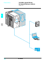
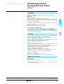
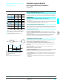
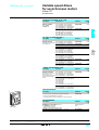
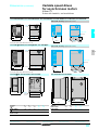
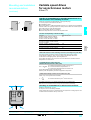
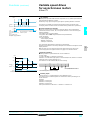
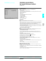
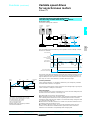
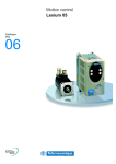
The Altivar 31 drive is a frequency inverter for 3-phase squirrel cage asynchronous
motors. The Altivar 31 is robust, compact and easy to set up. It conforms to EN
50178, IEC/EN 61800-2 and IEC/EN 61800-3 standards, UL and CSA certification
and the relevant European directives (e marking).
It incorporates functions that are suitable for the most common applications,
including:
b Materials handling (small conveyors, hoists, etc)
b Packing and packaging machines
b Specialist machines (mixers, kneaders, textile machines, etc.)
b Pumps, compressors, fans
2
Altivar 31 drives communicate on Modbus and CANopen industrial buses. Both
these protocols are integrated as standard in the drive.
Altivar 31 drives are supplied with a heatsink for normal environments and ventilated
enclosures. Several units can be mounted side-by-side 3, to save space.
Drives are available for motor ratings ranging from 0.18 kW to 15 kW, with four types
of power supply:
b 200 V to 240 V single phase, 0.18 kW to 2.2 kW
b 200 V to 240 V three phase, 0.18 kW to 15 kW
b 380 V to 500 V three phase, 0.37 kW to 15 kW
b 525 V to 600 V three phase, 0.75 kW to 15 kW
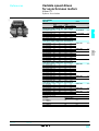
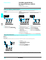
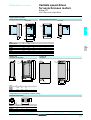
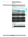
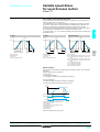
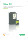
Altivar 31 drives are available with a choice of two different human-machine
interfaces:
b 1 ATV 31Hpppp with displays and menu navigation keys
b 2 ATV 31HppppA with displays, menu navigation keys and local control (Run/Stop
and speed reference set by a potentiometer).
Electromagnetic compatibility EMC
The incorporation of EMC filters in ATV 31HpppM2 and ATV 31HpppN4 drives
simplifies installation and provides an economical means of ensuring machines meet
e marking requirements
ATV 31HpppM3X and ATV 31HpppS6X drives are available without EMC filter.
Filters are available as an option and can be installed by the user if conformity to EMC
standards is required (see pages 2/120 and 2/121).
Functions
The Altivar 31 drive has six logic inputs, three analog inputs, one logic/analog output
and two relay outputs.
The main functions integrated in the drive are as follows:
b Motor and drive protection
b Linear, S, U or customized acceleration and deceleration ramps
b +/- speed
b 16 preset speeds
b PI regulator and references
b 2-wire/3-wire control
b Brake sequence
b Automatic catching a spinning load with speed detection and automatic restart
b Fault configuration and stop type configuration
b Saving the configuration in the drive
Several functions can be assigned to one logic input.
Options and accessories
The following options and accessories can be used with the Altivar 31 drive:
b Braking resistors
b Line chokes
b EMC radio interference input filters and output filters
b Plates for mounting on 5 rail
b UL Type 1 conformity kit
b Adaptor plate for replacing an Altivar 28 drive
Various dialogue and communication options 4, 5 and 6 can be used with the drive,
see pages 2/106 and 2/107.
Characteristics:
pages 2/108 to 2/111
References:
pages 2/112 to 2/115
Dimensions:
pages 2/126 to 2/131
Schemes:
pages 2/132 to 2/135
Functions:
pages 2/140 to 2/157
2/101
2.3
Presentation
2
Variable speed drives
for asynchronous motors
2
Altivar 31
Enclosed drives
2
ESC
ENT
stop
reset
FWO
REV
RUN
3
2.3
1
4
2
5
2/102
Presentation (continued)
2
Variable speed drives
for asynchronous motors
2
Altivar 31
Enclosed drives
Applications
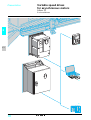
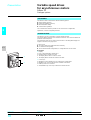
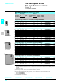
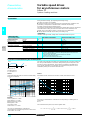
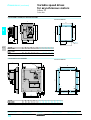
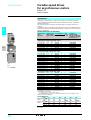
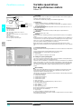
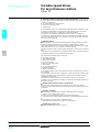
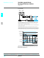
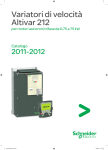
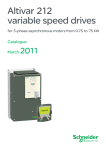
The enclosed Altivar 31 drive is suitable for applications requiring an IP 55 degree of
protection in a hostile environment.
This enclosed range of drives is available for motor ratings between 0.18 kW and
15 kW, with two types of power supply:
b 200 V to 240 V single phase, 0.18 kW and 2.2 kW
b 380 V to 500 V three phase, 0.37 kW and 15 kW
Up to 2.2 kW in single phase supply and 4 kW in three phase supply, the drive is
supplied in a customizable enclosure suitable for ready-to-use motor starter
applications. Above these power ratings, the drive is supplied in a standard
enclosure.
7
6
These enclosures can be installed next to the motor.
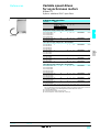
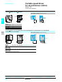
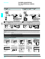
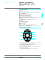
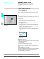
Customizable enclosed drive (0.18 kW to 4 kW)
This range allows full customization of the human-machine interface part of the
enclosure.
The IP 55 enclosure includes:
b A drive 1 with external heatsink
b Removable covers 6 to 9 for adding the following components:
6 Vario switch disconnector or GV2 circuit-breaker
7 3 buttons and/or LEDs with plastic flange (Ø 22) and 1 speed reference
potentiometer
8 1 blanking plug for the RJ45 connector with IP 55 cable
9 Cable glands for cable routing
8
9
The combinations (circuit-breaker, contactor, drive) required for the motor starter
function can be found on pages 2/138.
Example references:
b 3-pole Vario switch disconnector (Vpp + KCp 1pZ)
b Selector switch with 3 fixed positions XB5 D33
b LED XB5 AVpp
b 2.2 kΩ potentiometer VW3 A58866
These references can be found in our specialist "Motor starter solutions-Control and
protection components" and "Components for Human-Machine Interfaces"
catalogues.
All components must be ordered separately and wired by the customer.
Standard enclosed drive (5.5 kW to 15 kW)
This enclosure includes a drive 2 with external heatsink and fans and a blanking plug
10 for the RJ45 connector with IP 55 cable.
The combinations (circuit-breaker, contactor, drive) required for the motor starter
function can be found on page 2/138.
Electromagnetic compatibility EMC
The incorporation of EMC filters in ATV 31CpppM2 and ATV 31CpppN4 enclosed
drives simplifies installation and provides an economical means of ensuring machines
meet e marking requirements.
Options and accessories
The following options and accessories can be used with the enclosed Altivar 31
drive:
b Braking resistors
b Line chokes
b Output filters and motor chokes
b IP 55 cables equipped with RJ45 connectors for control via Modbus
10
Characteristics:
pages 2/108 to 2/111
References:
pages 2/112 to 2/115
2
Various dialogue and communication options 3, 4, 5 can be used with the drive (see
pages 2/106 and 2/107).
Dimensions:
pages 2/126 to 2/131
Schemes:
pages 2/132 to 2/135
Functions:
pages 2/140 to 2/157
2/103
2.3
Presentation (continued)
2
Variable speed drives
for asynchronous motors
2
Altivar 31
Drive kits
Applications
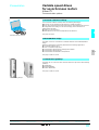
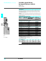
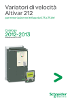
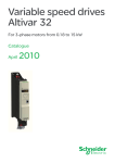
The drive kit is another standard solution available in the Altivar 31 drives offer.
The drive kit comprises:
b Altivar 31 drive elements (heatsink, power and control subassemblies)
b EMC filter
b Mechanical adaptors
b Seals required for use in difficult environments (IP 55)
The kit is mounted on a metal mounting support with no flange or protective cover.
The Altivar 31 drive kit can be built into a floor-standing or wall-mounted enclosure
or mounted on a machine frame.
2
The drive kit is available for motor ratings between 0.18 kW and 15 kW, with two
types of power supply:
b 200 V to 240 V single phase, 0.18 kW to 2.2 kW
b 380 V to 500 V three phase, 0.37 kW to 15 kW
Electromagnetic compatibility EMC
The incorporation of EMC filters in ATV 31KpppM2 and ATV 31KpppN4 drives
simplifies installation and provides an economical means of ensuring machines meet
e marking requirements. They are sized to conform to standard IEC/EN61800-3,
domestic and industrial environments.
2.3
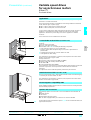
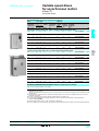
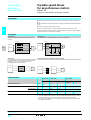
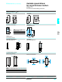
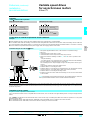
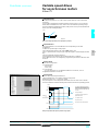
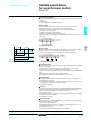
Description
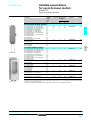
b Drive kit for power ratings y 4 kW 1
The Altivar 31 drive components (heatsink, power and control subassemblies) are
held in place by mechanical adaptors 2 and protective fittings.
The unit is supported by a metal plate 3 mounted on the heatsink.
A seal 4 is attached all around the plate.
Once the support has been cut out, the drive kit is mounted on the base of the floorstanding or wall-mounted enclosure by means of this plate.
The power terminals 5 are protected (IP 20).
b Drive kit for power ratings u 5.5 kW 6
The Altivar 31 drive components (heatsink, power and control subassemblies) are
held in place by mechanical adaptors 11 and protective fittings.
The metal support plate 7 for the components is equipped with brackets 10 for
mounting in a floor-standing or wall-mounted enclosure.
A seal 8 is attached all around the plate.
Two fans are installed behind the plate under the heatsink.
Additional mounting holes 9 are provided for mounting components (GV2 circuitbreaker, Vario switch disconnector, contactor, additional plate, etc.).
Drive kits are supplied with:
b A cutting and drilling template
b A user’s manual with installation instructions and safety precautions.
Options and accessories
The following options and accessories can be used with the Altivar 31 drive kit:
b Braking resistors
b Line chokes
b Output filters and motor chokes
Various dialogue and communication options 12, 13, 14 can be used with the drive
(see pages 2/106 and 2/107).
Characteristics:
pages 2/108 to 2/111
References:
pages 2/112 to 2/115
Dimensions:
pages 2/126 to 2/131
Schemes:
pages 2/132 to 2/135
Functions:
pages 2/140 to 2/157
2/105
Presentation
2
Variable speed drives
for asynchronous motors
Altivar 31
Dialogue options
Presentation
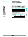
The Altivar 31 drive communicates with the following options:
b Remote display terminal
b PowerSuite software workshop
b Ethernet/Modbus bridge
b Communication gateways
The communication function provides access to the drive’s configuration,
adjustment, control and signalling functions.
2
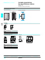
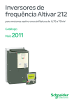
Remote terminal
The Altivar 31 can be connected to a remote display terminal.
The remote display terminal can be mounted on the door of an enclosure with IP 65
protection on the front panel.
The terminal provides access to the same functions as the integrated display and
keypad on the drive, see page 2/141.
It can be used:
b To control, adjust and configure the drive remotely
b For visible remote signalling
b To save and download configurations; 4 configuration files can be saved.
563220
2.3
1
ESC
ENT
2
stop
reset
FWO
REV
RUN
Characteristics:
pages 2/108 to 2/111
2/106
References:
pages 2/112 to 2/115
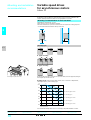
Description
1 Display
v Four 7-segment displays visible at 5 m
v Displays numeric values and codes
v The display flashes when a value is stored.
v The display flashes to indicate a fault on the drive.
2
v
v
v
v
Use of keys:
Navigation arrows and ENT, ESC for settings and configurations
FWD/REV key: reverses the direction of rotation of the motor
RUN key: motor run command
STOP/RESET key: motor stop command or drive fault reset
Dimensions:
pages 2/126 to 2/131
Schemes:
pages 2/132 to 2/135
Functions:
pages 2/140 to 2/157
2
Presentation
2
Variable speed drives
for asynchronous motors
2
Altivar 31
Communication options
563019
PowerSuite software workshop
The PowerSuite software workshop offers the following advantages:
b Messages can be displayed in plain text and in multiple languages
b Work can be prepared in the design office without connecting the drive to the PC
b Configurations and settings can be saved to floppy disk or hard disk and
downloaded to the drive
b Settings can be printed out
b Altivar 28 files can be read and imported into the Altivar 31
2
See pages 3/2 to 3/5.
PowerSuite software workshop
Ethernet/Modbus bridge
The Altivar 31 can be connected to an Ethernet network via an Ethernet/Modbus
bridge.
Ethernet communication is primarily intended for the following applications:
b Coordination between PLCs
b Local or centralized supervision
b Communication with production management software
b Communication with remote I/O
b Communication with industrial control products
563017
See pages 2/124 and 2/125.
563018
Communication gateways
The Altivar 31 can connect to other communication buses by means of the following
gateways:
b Fipio/Modbus
b DeviceNet/Modbus
b Profibus DP/Modbus
See pages 2/124 and 2/125.
Communication gateways
Characteristics:
pages 2/108 to 2/111
References:
pages 2/112 to 2/115
Dimensions:
pages 2/126 to 2/131
Schemes:
pages 2/132 to 2/135
Functions:
pages 2/140 to 2/157
2/107
2.3
Characteristics
2
Variable speed drives
for asynchronous motors
Altivar 31
Environmental characteristics
Conformity to standards
Altivar 31 drives have been developed to conform to the strictest international
standards and the recommendations relating to electrical industrial control devices
(IEC, EN), in particular:
low-voltage EN 50178, EMC immunity and EMC conducted and radiated emissions.
IEC/EN 61000-4-2 level 3
IEC/EN 61000-4-3 level 3
IEC/EN 61000-4-4 level 4
IEC/EN 61000-4-5 level 3 (power part)
IEC/EN 61800-3, environments 1 and 2
EMC immunity
2
EMC conducted and radiated emissions for drives
All drives
IEC/EN 61800-3, environments: 2 (industrial supply) and 1 (public supply), restricted
distribution
EN 55011 class A group 1, EN 61800-3 category C2
With additional EMC filter:
b EN 55022 class B group 1, EN 61800-3 category C1
ATV 31H018M2...HU15M2,
ATV 31C018M2...CU15M2,
ATV 31H037N4...HU40N4,
ATV 31C037N4...CU40N4
ATV 31HU22M2,
ATV 31CU22M2,
ATV 31HU55N4...HD15N4,
ATV 31CU55N4...CD15N4
ATV 31H018M3X...HD15M3X,
ATV 31H075S6X....HD15S6X
2.3
EN 55011 class A group 2, EN 61800-3 category C3
With additional EMC filter (1) :
b EN 55022 class A group 1, EN 61800-3 category C2
b EN 55022 class B group 1, EN 61800-3 category C1
With additional EMC filter (1):
b EN 55011 class A group 1, EN 61800-3 category C2
b EN 55022 class B group 1, EN 61800-3 category C1
The drives carry e marking in accordance with the European low voltage
(73/23/EEC and 93/68/EEC) and EMC (89/336/EEC) directives
C-Tick
UL, CSA, N998
e marking
Product certifications All drives
ATV 31H/Kppppp, ATV 31HpppppX,
ATV 31CpppM2,
ATV 31C037N4…CU40N4
Degree of protection ATV 31HpppM2, ATV 31HpppN4,
ATV 31HpppM3X, ATV 31HpppS6X
ATV 31CpppM2, ATV 31CpppN4
Degree of pollution
Climatic treatment
Vibration resistance
Drive without rail option 5
Shock resistance
Relative humidity
Ambient temperature
around the unit
%
°C
Storage
Operation
ATV 31Hppp
ATV 31C/Kppp
Maximum operating altitude
Operating position
Maximum permanent angle in relation to the normal vertical
mounting position
°C
°C
m
IP 31 and IP 41 on upper part and IP 21 on connection terminals
IP 20 without cover plate on upper part of cover
IP 55
2
TC
Conforming to IEC/EN 60068-2-6: 1.5 mm peak to peak from 3 to 13 Hz, 1 gn from
13 to 150 Hz
15 gn for 11 ms conforming to IEC/EN 60068-2-27
5…95 without condensation or dripping water, conforming to IEC 60068-2-3
- 25…+ 70
-10…+50 without derating, with protective cover on top of the drive
-10…+60 with derating, without protective cover on top of the drive (see derating
curves, page 2/134)
-10…+40 without derating
1000 without derating (above this, derate the current by 1% per additional 100 m)
Drive characteristics
Output frequency range
Switching frequency
Speed range
Transient overtorque
Braking torque
With braking resistor
Without braking resistor
Maximum transient current
Voltage/frequency
ratio
Frequency loop gain
Slip compensation
2/108
Hz
kHz
0…500
2…16 adjustable during operation
1…50
170 to 200% of nominal motor torque (typical value)
100% of nominal motor torque continuously and up to 150% for 60 s
Value of nominal motor torque (typical value) according to ratings:
30% for > ATV 31pU15pp
50% for y ATV 31pU15pp
100% for y ATV 31p075pp
150% for y ATV 31p018M2
150% of the nominal drive current for 60 seconds (typical value)
Sensorless flux vector control with PWM (Pulse Width Modulation)
type motor control signal
Factory-set for most constant torque applications
Possible options: specific ratios for pumps and fans, energy saving or constant torque
U/f for special motors
Factory-set with the speed loop stability and gain
Possible options for machines with high resistive torque or high inertia, or for machines
with fast cycles
Automatic whatever the load. Can be suppressed or adjusted
(1) See table on page 2/121 to check permitted cable lengths.
2
Characteristics (continued)
2
Variable speed drives
for asynchronous motors
2
Altivar 31
Electrical characteristics
Power supply
Voltage
V
Frequency
Hz
200 -15% … 240 +10% single phase for ATV 31ppppM2
200 -15% … 240 +10% 3-phase for ATV 31ppppM3X
380 -15% … 500 +10% 3-phase for ATV 31ppppN4
525 -15% … 600 +10% 3-phase for ATV 31ppppS6X
50 -5% … 60 +5%
A
A
≤ 1000 (ISC at connection point) for single phase power supply
≤ 5000 (ISC at connection point) for 3-phase power supply
A
≤ 22000 (ISC at connection point) for 3-phase power supply
Prospective short-circuit For drives
current ISC
ATV 31ppppM2
ATV 31H018M3X…HU40M3X,
ATV 31H/C/K037N4…H/C/KU40N4,
ATV 31H075S6X…HU40S6X
ATV 31HU55M3X…HD15M3X,
ATV 31HU55N4…HD15N4,
ATV 31CU55N4…CD15N4,
ATV 31KU55N4…KD15N4,
ATV 31HU55S6X…HD15S6X
Output voltage
Maximum connection
For drives
capacity and tightening ATV 31H/C/K018M2…H/C/K075M2,
torque of the power
ATV 31H018M3X…HU15M3X
supply
ATV 31H/C/KU11M2…H/C/KU22M2,
terminals,
ATV 31HU22M3X…HU40M3X,
motor,
ATV 31H/C/K037N4…H/C/KU40N4,
braking module and
ATV 31H075S6X…HU40S6X
DC bus
ATV 31HU55M3X, HU75M3X,
ATV 31H/C/KU55N4, H/C/KU75N4,
ATV 31HU55S6X, HU75S6X
ATV 31HD11M3X, HD15M3X,
ATV 31H/C/KD11N4, H/C/KD15N4,
ATV 31HD11S6X, HD15S6X
Electrical isolation
Internal supplies
available
Configurable analog
inputs
Al1
Al2
Al3
Analog voltage
or current
outputs configurable as AOV
logic outputs
AOC
Configurable relay
outputs
R1A, R1B, R1C
R2A, R2B
Presentation:
pages 2/100 to 2/107
References:
pages 2/112 to 2/115
2
Maximum 3-phase voltage equal to line supply voltage
2.5 mm2 (AWG 14)
0.8 Nm
5 mm2 (AWG 10)
1.2 Nm
2.3
16 mm2 (AWG 6)
2.2 Nm
25 mm2 (AWG 3)
4 Nm
Electrical isolation between power and control (inputs, outputs, power supplies)
Short-circuit and overload protection:
b One +10 V (0/+8%) supply for the reference potentiometer (2.2 to 10 kΩ), maximum
current 10 mA
b One +24 V supply (min. 19 V, max. 30 V) for logic inputs, maximum current 100 mA
Analog voltage input 0 to +10V, impedance 30 kΩ,maximum safe voltage 30 V
Analog bipolar voltage input ±10 V, impedance 30 kΩ, maximum safe voltage 30 V
Analog current input X-Y mA by programming X and Y from 0 to 20 mA, with
impedance 250Ω
AIP: potentiometer reference for ATV 31ppppppA only
Max. sampling time: 8 ms
10-bit resolution
Precision ± 4.3%
Linearity ± 0.2% of maximum value
Use:
b 100 m maximum with shielded cable
b 25 m maximum with unshielded cable
2 assignable analog outputs AOV and AOC
These outputs cannot be used at the same time
Analog voltage output 0..+10 V, minimum load impedance 470 Ω
8-bit resolution, precision ±1%, linearity ±0.2%
Analog current output 0…20 mA, maximum load impedance 800 Ω
8-bit resolution, precision ±1%, linearity ±0.2%
This AOC analog output can be configured as a 24 V logic output, max. 20 mA,
minimum load impedance 1.2 kΩ
Max. sampling time: 8 ms
1 relay logic output, one "N/C" contact and one "N/O" contact with common point.
Minimum switching capacity: 10 mA for c 5 V
Maximum switching capacity:
b on resistive load (cos ϕ = 1 and L/R = 0 ms): 5 A for a 250 V or c 30 V,
b on inductive load (cos ϕ = 0.4 and L/R = 7 ms): 2 A for a 250 V or c 30 V
Max. sampling time: 8 ms
Switching: 100,000 operations
1 relay logic output, one "N/C" contact, contact open on fault.
Minimum switching capacity: 10 mA for c 5 V
Maximum switching capacity:
b on resistive load (cos ϕ = 1 and L/R = 0 ms): 5 A for a 250 V or c 30 V,
b on inductive load (cos ϕ = 0.4 and L/R = 7 ms): 2 A for a 250 V or c 30 V
Max. sampling time: 8 ms
Switching: 100,000 operations
Dimensions:
pages 2/126 to 2/131
Schemes:
pages 2/132 to 2/135
Functions:
pages 2/140 to 2/157
2/109
Characteristics (continued)
2
Variable speed drives
for asynchronous motors
Altivar 31
Electrical characteristics (continued)
Logic inputs LI
2
LI1…LI6
6 programmable logic inputs
Impedance 3.5 kΩ
+ 24 V internal or 24 V external power supply (min. 19 V, max. 30 V)
Max. current: 100 mA
Max. sampling time: 4 ms
Multiple assignment makes it possible to configure several functions on one input
(example: LI1 assigned to forward and preset speed 2, LI3 assigned to reverse and
preset speed 3)
State 0 if < 5 V or logic input not wired, state 1 if > 11 V
State 0 if > 19 V or logic input not wired, state 1 if < 13 V
Connection to PLC output (see diagram, page 2/132)
2.5 mm2 (AWG 14)
0.6 Nm
Ramp profiles:
b Linear, can be adjusted separately from 0.1 to 999.9 s
b S, U or customized
Automatic adaptation of deceleration ramp time if braking capacities are exceeded,
possible inhibition of this adaptation (use of braking resistor)
By d.c. injection:
b by a signal on a programmable logic input
b automatically as soon as the estimated output frequency drops to < 0.5 Hz, period
adjustable from 0 to 30 s or continuous, current adjustable from 0 to 1.2 In
Thermal protection against overheating
Protection against short-circuits between motor phases
Protection against input phase breaks
Protection against motor phase breaks
Protection against overcurrent between output phases and earth
Line supply overvoltage and undervoltage safety circuits
Line supply phase loss safety function, for 3-phase supply
Thermal protection integrated in the drive by continuous calculation of the l 2t
Positive logic
Negative logic
CLI position
Maximum I/O connection capacity and tightening torque
Acceleration and deceleration ramps
Braking to a standstill
Main protection and safety features of the drive
2.3
Motor protection
(see page 2/153)
Dielectric strength
Between earth and power
terminals
Between control and power
terminals
Insulation resistance to earth
Signalling
Frequency resolution
Display units
Analog inputs
Time constant for reference change
Communication
Modbus
CANopen
Presentation:
pages 2/100 to 2/107
2/110
References:
pages 2/112 to 2/115
Hz
Hz
ms
2040 V c for ATV 31ppppM2 and M3X, 2410 V c for ATV 31ppppN4,
2550 V c for ATV 31ppppS6X
2880 V a for ATV 31ppppM2 and M3X, 3400 V a for ATV 31ppppN4,
3600 V a for ATV 31ppppS6X
> 500 MΩ (electrical isolation) 500 V c for 1 minute
1 red LED on front: LED lit indicates the presence of drive voltage
Display coded by four 7-segment display units displaying the CANopen bus status
(RUN and ERR).
0.1
0.1 …100 Hz (calculate (high speed – low speed)/1024)
5
Modbus and CANopen are integrated into the drive and available via an RJ45
connector
RS 485 multidrop serial link
Modbus in RTU mode
Services supported: decimal function codes 03, 06, 16, 23 and 43
Broadcasting
Number of addresses: drive address can be configured via the integrated terminal
from 1 to 247
Maximum number of Altivar 31 drives connected: 31
Transmission speed: 4800, 9600 or 19200 bps
Used for connecting:
b the remote terminal (option)
b the PowerSuite software workshop
b a PLC
b a microprocessor card
b a PC
To connect the ATV31 drive on the CANopen bus, use the VW3 CANTAP2 adapter
Services supported:
b Implicit exchange of Process Data Object
- 2 PDOs depending on DSP 402 velocity mode
- 2 configurable PDOs (data and transmission type)
- PDOs can be exchanged between slaves.
b Explicit exchange of Service Data Object
- 1 receive SDO and 1 transmit SDO
b Boot-up messages, emergency messages, node guarding and producer and
consumer heartbeat, sync and NMT
Number of addresses: drive address can be configured via the integrated terminal
from 1 to 127
Maximum number of Altivar 31 drives connected: 127
Transmission speed: 10, 20, 50, 125, 250, 500 kbps or 1 Mbps
Dimensions:
pages 2/126 to 2/131
Schemes:
pages 2/132 to 2/135
Functions:
pages 2/140 to 2/157
2
Characteristics (continued),
special uses
2
Variable speed drives
for asynchronous motors
2
Altivar 31
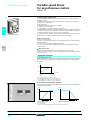
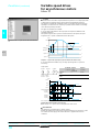
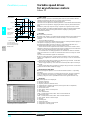
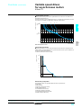
Torque characteristics (typical curves)
The curves opposite define the available continuous torque and transient overtorque
for both force-cooled and self-cooled motors. The only difference is in the ability of
the motor to provide a high continuous torque at less than half the nominal speed.
Tn
2,25
2
1,75
1,7
Special uses
3
Use with a motor with a different rating to that of the drive
The device can supply any motor which has a power rating lower than that for which
it is designed.
For motor ratings slightly higher than that of the drive, check that the current taken
does not exceed the continuous output current of the drive.
1,50
1,25
1
0,95
2
0,75
1
Test on a low power motor or without a motor
In a testing or maintenance environment the drive can be checked without having to
switch to a motor with the same rating as the drive (particularly useful in the case of
high power drives). This use requires deactivation of motor phase loss detection.
4
0,50
0,25
0
0
1
2
3
4
2
25/30
75/90
50/60
Hz
100/120
Self-cooled motor: continuous useful torque (1)
Force-cooled motor: continuous useful torque
Transient overtorque 1.7 to 2 Tn
Torque in overspeed at constant power (2)
KM1
Altivar 31
M
N
t1 > 500 ms
Connecting motors in parallel
The nominal current of the drive must be greater than or equal to the sum of the
currents of the motors to be controlled.
In this case, external thermal protection must be provided for each motor using
probes or LRD thermal bimetal overload relays designed for 1.2 times the nominal
current of the motor.
If the number of motors connected in parallel is greater than or equal to 3, it is
advisable to install a motor choke between the drive and the motors.
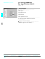
Switching the motor at the drive output
The drive can be switched when locked or unlocked. If the drive is switched on-thefly (drive unlocked), the motor is controlled and accelerates until it reaches the
reference speed smoothly following the acceleration ramp.
This use requires configuration of automatic catching a spinning load
("catch on-the-fly"), activation of the function which manages the presence of a
downstream contactor and addition of ferrite suppressors at the drive output, see
page 2/123.
t
Typical applications: loss of safety circuit at drive output, bypass function,
switching of motors connected in parallel
t
Operating recommendations: synchronize the control of the downstream contactor
with that of a freewheel stop request sent by the drive on a logic input.
t2
1
KM1 0
KM1: contactor
t1: KM1 opening time (motor freewheeling)
t2: acceleration with ramp
N: speed
Example of breaking of downstream contactor
(1) For power ratings ≤ 250 W, the motor is derated to a lesser extent (20% instead of 50% at
very low frequencies).
(2) The nominal motor frequency and the maximum output frequency can be adjusted from
40 to 500 Hz.
Note: Check the mechanical overspeed characteristics of the selected motor with the
manufacturer.
Presentation:
pages 2/100 to 2/107
Dimensions:
pages 2/126 to 2/131
References:
pages 2/112 to 2/115
Schemes:
pages 2/132 to 2/135
Functions:
pages 2/140 to 2/157
2/111
2.3
References
2
Variable speed drives
for asynchronous motors
2
Altivar 31
Drives with heatsink
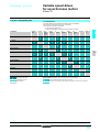
Drives with heatsink (frequency range from 0.5 to 500 Hz)
Motor
Line supply
Power
Line current
indicated on
(2)
rating plate (1)
at U1 at U2
(3)
kW
HP
A
A
Apparent Max.
power
prospective
line Isc (4)
Altivar 31
Nominal Max.
current transient
current for
60 s
4 kHz
Power
Reference (5)
dissipated
at nominal
load
kVA
A
W
kA
A
Weight
kg
2
531248
Single phase supply voltage: 200…240 V 50/60 Hz, with integrated EMC filters
ATV 31H037M2
0.18
0.37
0.55
0.75
1.1
1.5
2.2
0.25
0.5
0.75
1
1.5
2
3
3.0
5.3
6.8
8.9
12.1
15.8
21.9
2.5
4.4
5.8
7.5
10.2
13.3
18.4
0.6
1
1.4
1.8
2.4
3.2
4.4
1
1
1
1
1
1
1
1.5
3.3
3.7
4.8
6.9
8
11
2.3
5
5.6
7.2
10.4
12
16.5
24
41
46
60
74
90
123
ATV 31H018M2 (6)
ATV 31H037M2 (6)
ATV 31H055M2 (6)
ATV 31H075M2 (6)
ATV 31HU11M2 (6)
ATV 31HU15M2 (6)
ATV 31HU22M2 (6)
1.500
1.500
1.500
1.500
1.800
1.800
3.100
531249
3-phase supply voltage: 200…240 V 50/60 Hz, without EMC filters (7)
2.3
ATV 31HU40M3X
0.18
0.37
0.55
0.75
1.1
1.5
2.2
3
4
5.5
7.5
11
15
0.25
0.5
0.75
1
1.5
2
3
–
5
7.5
10
15
20
2.1
3.8
4.9
6.4
8.5
11.1
14.9
19.1
24.2
36.8
46.8
63.5
82.1
1.9
3.3
4.2
5.6
7.4
9.6
13
16.6
21.1
32
40.9
55.6
71.9
0.7
1.3
1.7
2.2
3
3.8
5.2
6.6
8.4
12.8
16.2
22
28.5
5
5
5
5
5
5
5
5
5
22
22
22
22
1.5
3.3
3.7
4.8
6.9
8
11
13.7
17.5
27.5
33
54
66
2.3
5
5.6
7.2
10.4
12
16.5
20.6
26.3
41.3
49.5
81
99
23
38
43
55
71
86
114
146
180
292
388
477
628
ATV 31H018M3X (6)
ATV 31H037M3X (6)
ATV 31H055M3X (6)
ATV 31H075M3X (6)
ATV 31HU11M3X (6)
ATV 31HU15M3X (6)
ATV 31HU22M3X (6)
ATV 31HU30M3X (6)
ATV 31HU40M3X (6)
ATV 31HU55M3X (6)
ATV 31HU75M3X (6)
ATV 31HD11M3X (6)
ATV 31HD15M3X (6)
1.300
1.300
1.300
1.300
1.700
1.700
1.700
2.900
2.900
6.400
6.400
10.500
10.500
32
37
41
48
61
79
125
150
232
269
397
492
ATV 31H037N4 (6)
ATV 31H055N4 (6)
ATV 31H075N4 (6)
ATV 31HU11N4 (6)
ATV 31HU15N4 (6)
ATV 31HU22N4 (6)
ATV 31HU30N4 (6)
ATV 31HU40N4 (6)
ATV 31HU55N4 (6)
ATV 31HU75N4 (6)
ATV 31HD11N4 (6)
ATV 31HD15N4 (6)
1.800
1.800
1.800
1.800
1.800
3.100
3.100
3.100
6.500
6.500
11.000
11.000
36
48
62
94
133
165
257
335
ATV 31H075S6X
ATV 31HU15S6X
ATV 31HU22S6X
ATV 31HU40S6X
ATV 31HU55S6X
ATV 31HU75S6X
ATV 31HD11S6X
ATV 31HD15S6X
1.700
1.700
2.900
2.900
6.200
6.200
10.000
10.000
531250
3-phase supply voltage: 380…500 V 50/60 Hz, with integrated EMC filters
531251
ATV 31HU75N4
0.37
0.55
0.75
1.1
1.5
2.2
3
4
5.5
7.5
11
15
0.5
0.75
1
1.5
2
3
–
5
7.5
10
15
20
2.2
2.8
3.6
4.9
6.4
8.9
10.9
13.9
21.9
27.7
37.2
48.2
1.7
2.2
2.7
3.7
4.8
6.7
8.3
10.6
16.5
21
28.4
36.8
1.5
1.8
2.4
3.2
4.2
5.9
7.1
9.2
15
18
25
32
5
5
5
5
5
5
5
5
22
22
22
22
1.5
1.9
2.3
3
4.1
5.5
7.1
9.5
14.3
17
27.7
33
2.3
2.9
3.5
4.5
6.2
8.3
10.7
14.3
21.5
25.5
41.6
49.5
3-phase supply voltage: 525…600 V 50/60 Hz, without EMC filters
0.75
1.5
2.2
4
5.5
7.5
11
15
ATV 31HD15N4A
Presentation:
pages 2/100 to 2/107
2/112
1
2
3
5
7.5
10
15
20
2.8
4.8
6.4
10.7
16.2
21.3
27.8
36.4
2.4
4.2
5.6
9.3
14.1
18.5
24.4
31.8
2.5
4.4
5.8
9.7
15
19
25
33
5
5
5
5
22
22
22
22
1.7
2.7
3.9
6.1
9
11
17
22
2.6
4.1
5.9
9.2
13.5
16.5
25.5
33
(1) These power ratings are for a maximum switching frequency of 4 kHz, in continuous operation. The switching frequency is
adjustable from 2 to 16 kHz.
Above 4 kHz, derate the nominal drive current. The nominal motor current should not exceed this value: see derating curves on
page 2/134.
(2) Typical value for a 4-pole motor and a maximum switching frequency of 4 kHz, with no additional line choke, for the max.
prospective line current.
(3) Nominal supply voltages, min. U1, max. U2 (200-240 V; 380-500 V; 525-600 V).
(4) If line Isc is greater than the values in the table, add line chokes, see page 2/119.
(5) To order a drive intended for wire guiding applications, add a T to the end of the reference for the selected drive.
Example: ATV 31H018M2T.
(6) To order a drive with potentiometer, add an A to the end of the reference for the selected drive.
Example: ATV 31H018M2A.
(7) Optional EMC filter, see page 2/121.
Characteristics:
pages 2/108 to 2/111
Dimensions:
pages 2/126 and 2/127
Schemes:
pages 2/132 to 2/135
Functions:
pages 2/140 to 2/157
References (continued)
2
Variable speed drives
for asynchronous motors
2
Altivar 31
Enclosed drives
Enclosed drives (frequency range from 0.5 to 500 Hz)
Motor
Power
indicated on
rating plate (1)
Line supply
Line current
(2)
at U1 at U2
Apparent Max.
power
prospective
line Isc (3)
kW
A
KVA
HP
A
kA
Altivar 31
Nominal Max.
current transient
current for
4 kHz
60 s
A
A
Power
Reference (4)
dissipated
at nominal
load
W
Weight
kg
531252
Single phase supply voltage: 200…240 V (5) 50/60 Hz with integrated EMC filters
0.18
0.25
3
2.5
0.6
1
1.5
2.3
24
ATV 31C018M2 (6)
6.300
0.37
0.5
5.3
4.4
1
1
3.3
5
41
ATV 31C037M2 (6)
6.300
0.55
0.75
6.8
5.8
1.4
1
3.7
5.6
46
ATV 31C055M2 (6)
6.300
0.75
1
8.9
7.5
1.8
1
4.8
7.2
60
ATV 31C075M2 (6)
6.300
1.1
1.5
12.1 10.2
2.4
1
6.9
10.4
74
ATV 31CU11M2 (6)
8.800
1.5
2
15.8 13.3
3.2
1
8
12
90
ATV 31CU15M2 (6)
8.800
2.2
3
21.9 18.4
4.4
1
11
16.5
123
ATV 31CU22M2 (6)
10.700
2
ATV 31CU22M2
534445
3-phase supply voltage: 380…500 V (5) 50/60 Hz with integrated EMC filters
ATV 31CU75N4
0.37
0.5
2.2
1.7
1.5
5
1.5
2.3
32
ATV 31C037N4 (6)
8.800
0.55
0.75
2.8
2.2
1.8
5
1.9
2.9
37
ATV 31C055N4 (6)
8.800
0.75
1
3.6
2.7
2.4
5
2.3
3.5
41
ATV 31C075N4 (6)
8.800
1.1
1.5
4.9
3.7
3.2
5
3
4.5
48
ATV 31CU11N4 (6)
8.800
1.5
2
6.4
4.8
4.2
5
4.1
6.2
61
ATV 31CU15N4 (6)
8.800
2.2
3
8.9
6.7
5.9
5
5.5
8.3
79
ATV 31CU22N4 (6)
10.700
3
–
10.9 8.3
7.1
5
7.1
10.7
125
ATV 31CU30N4 (6)
10.700
4
5
13.9 10.6
9.2
5
9.5
14.3
150
ATV 31CU40N4 (6)
10.700
5.5
7.5
21.9 16.5
15.0
22
14.3
21.5
232
ATV 31CU55N4
23.600
7.5
10
27.7 21.0
18.0
22
17.0
25.5
269
ATV 31CU75N4
23.600
11
15
37.2 28.4
25.0
22
27.7
41.6
397
ATV 31CD11N4
32.500
15
20
48.2 36.8
32.0
22
33.0
49.5
492
ATV 31CD15N4
32.500
Ready-assembled enclosed drives (frequency range from 0.5 to 500 Hz)
Please consult your Regional Sales Office.
(1) These power ratings are for a maximum switching frequency of 4 kHz, in continuous operation. The switching frequency is
adjustable from 2 to 16 kHz.
Above 4 kHz, derate the nominal drive current. The nominal motor current should not exceed this value: see derating curves
on page 2/134.
(2) Typical value for a 4-pole motor and a maximum switching frequency of 4 kHz, with no additional line choke, for the max.
prospective line current.
(3) If line Isc is greater than the values in the table, add line chokes, see page 2/119.
(4) To order a drive intended for wire guiding applications, add a T to the end of the reference for the selected drive.
Example: ATV 31C018M2T.
(5) Nominal supply voltages, min. U1, max. U2 (200-240 V; 380-500 V).
(6) ATV 31C18M2 to ATV 31CU40N4 drives are supplied in customizable enclosures for ready-to-use motor starter applications.
Presentation:
pages 2/100 to 2/107
Characteristics:
pages 2/108 to 2/111
Dimensions:
page 2/127
Schemes:
pages 2/132 to 2/135
Functions:
pages 2/140 to 2/157
2/113
2.3
References (continued)
2
Variable speed drives
for asynchronous motors
2
Altivar 31
Accessories
Plates for mounting on 5 rail
Description
Plate for mounting
on 5 rail,
width 35 mm
For drives
Reference
ATV 31H018M2, ATV 31H037M2,
ATV 31H055M2, ATV 31H075M2,
ATV 31H018M3X, ATV 31H037M3X,
ATV 31H055M3X, ATV 31H075M3X
ATV 31HU11M2, ATV 31HU15M2,
ATV 31HU11M3X, ATV 31HU15M3X,
ATV 31HU22M3X, ATV 31H037N4,
ATV 31H055N4, ATV 31H075N4,
ATV 31HU11N4, ATV 31HU15N4,
ATV 31H075S6X, ATV 31HU15S6X
VW3 A11851
Weight
kg
0.200
VW3 A31852
0.220
2
UL Type 1 conformity kits (1)
Description
For drives
Mechanical device
ATV 31H018M2, ATV 31H037M2,
for fixing to the underside ATV 31H055M2, ATV 31H075M2
of the Altivar 31
ATV 31H018M3X, ATV 31H037M3X,
ATV 31H055M3X, ATV 31H075M3X
ATV 31HU11M3X, ATV 31HU15M3X
ATV 31HU11M2, ATV 31HU15M2,
ATV 31HU22M3X, ATV 31H037N4,
ATV 31H055N4, ATV 31H075N4,
ATV 31HU11N4, ATV 31HU15N4,
ATV 31H075S6X, ATV 31HU15S6X
ATV 31HU22M2, ATV 31HU30M3X,
ATV 31HU40M3X, ATV 31HU22N4,
ATV 31HU30N4, ATV 31HU40N4,
ATV 31HU22S6X, ATV 31HU40S6X
ATV 31HU55M3X, ATV 31HU75M3X,
ATV 31HU55N4, ATV 31HU75N4,
ATV 31HU55S6X, ATV 31HU75S6X
ATV 31HD11M3X, ATV 31HD15M3X,
ATV 31HD11N4, ATV 31HD15N4,
ATV 31HD11S6X, ATV 31HD15S6X
Reference
VW3 A31812
Weight
kg
0.400
VW3 A31811
0.400
VW3 A31813
VW3 A31814
0.400
0.500
2.3
VW3 A31815
0.500
VW3 A31816
0.900
VW3 A31817
1.200
Altivar 28 substitution kits
Description
Mechanical adapters
allowing an ATV 31 to be
used in place of an
ATV 28 of the same rating
(using the same fixing
holes)
For drives
Reference
ATV 31H018M2, ATV 31H037M2,
VW3 A31821
ATV 31H055M2, ATV 31H075M2,
ATV 31H018M3X, ATV 31H037M3X,
ATV 31H055M3X, ATV 31H075M3X
ATV 31HU11M2, ATV 31HU15M2,
VW3 A31822
ATV 31HU11M3X, ATV 31HU15M3X,
ATV 31HU22M3X,
ATV 31H037N4,
ATV 31H075N4,
ATV 31HU15N4,
ATV 31H075S6X, ATV 31HU15S6X
ATV 31HU55N4, ATV 31HU75N4,
VW3 A31823
ATV 31HU55M3X, ATV 31HU75M3X,
ATV 31HU55S6X, ATV 31HU75S6X
Weight
kg
–
–
–
803679
Remote terminal
Description
Reference
For ATV31 drives of all ratings, assembly comprising:
- terminal, cable fitted with 2 connectors
- seal and screws for IP 65 mounting on an enclosure door
VW3 A31101
Weight
kg
–
ESC
Documentation
ENT
Description
stop
reset
FWO
REV
Reference
RUN
Simplified user’s manual for ATV 31
Supplied with the
and CD-ROM, comprising:
drive
- Variables user’s manual
- Modbus and CANopen user’s manual
International Technical Manual (MIT)
CD-ROM
DCI CD39811
0.150
(1) This device can be used to connect cables directly to the drive via tubes or cable gland.
VW3 A31101
Presentation:
pages 2/100 to 2/107
Weight
kg
–
Characteristics:
pages 2/108 to 2/111
Dimensions:
page 2/129
Functions:
pages 2/140 to 2/157
2/115
Presentation,
characteristics
2
Variable speed drives
for asynchronous motors
2
Altivar 31
Options: braking resistors
Presentation
The resistor enables the Altivar 31 drive to operate while braking to a standstill or
during slowdown braking, by dissipating the braking energy.
Two types of resistors are available:
b Enclosed model (IP 20 casing) designed to comply with EMC regulations and
protected by a temperature-controlled switch or thermal overload relay.
It enables maximum transient braking torque.
The resistors are designed to be mounted on the outside of the enclosure, but should
not inhibit natural cooling. Air inlets and outlets must not be obstructed, even
partially. The air must be free of dust, corrosive gas and condensation.
b Non-protected model (IP 00) for lower power ratings only.
Applications
Machines with high inertia, driving loads and machines with fast cycles.
2
Characteristics
Type of braking resistor
Ambient temperature
around the device
VW3 A7 701 to VW3 A7 705
0…+ 50
- 25…+ 70
IP 00
IP 20
None
Via temperature controlled switch or via
the drive
Temperature controlled
Tripping temperature
°C
–
120
switch (1)
–
250 V a -1 A
Max. voltage - max. current
–
24 V c -0.1 A
Min. voltage - min. current
Maximum contact resistance
mΩ
–
60
The value of the average power that can be dissipated at 40°C from the resistor into
Load factor of the dynamic brake transistors
the casing is determined for a load factor during braking that corresponds to the
majority of common application.
The dynamic brake transistor is designed so that it can tolerate:
- continuous nominal motor power,
- 150 % of the nominal motor power for 60 s.
(1) The contact should be connected in sequence (used for signalling or controlling the line contactor).
Operation
Storage
Degree of protection of enclosure
Thermal protection
2.3
VW3 A58702 to VW3 A58704
40
°C
Load factor and determining the nominal power
The value of the average power that can be dissipated at 40°C from the resistor into
the casing is determined for a load factor during braking that corresponds to the
majority of common applications. This load factor is defined in the table above.
For a specific application (e.g. handling), the nominal resistor power has to be
redefined by taking account of the new load factor.
Speed
0
t
Time
T
Load factor: --tT
t: Braking time in s
T: Cycle time in s
Chart 1
Graph of the average power as a function of the braking
torque for a load factor
Chart 2
Permissible resistor overload as a function of time (characteristic curve)
K1
K2
1
20
0,1
60%
40%
18
20%
14
10%
12
5%
10
2%
8
7
6
0,06
0,01
16
4
2
t (s)
0
1
0,001
0,1
0,5 0,6
1
10
100
1000
1,5 Tb/Tn
Example:
Motor of power Pm = 4 kW
Motor efficiency η = 0.85
Braking torque Tb = 0.6 Tn
Braking time t = 10 s
Cycle time t = 50 s
Load factor Lf = --t- = 20%
Use chart 2 to determine the coefficient K2 corresponding to a braking time of
10 seconds.
K2 = 7
The nominal resistor power (Pn) must be greater than:
T
Use chart 1 to determine the coefficient K1
corresponding to a braking torque of 0.6 Tn and a load
factor of 20%. K1 = 0.06
2/116
1 - ) = 4. 10 3 × 0,06 × 0,8 (1 + -----------------)
1
Pn = Pm × K1 × η(1 + -------------------= 350 W
K2 × fm
7 × 0,2
References
2
Variable speed drives
for asynchronous motors
2
Altivar 31
Options: braking resistors
For drives
Minimum
resistor
value
(1)
Ω
Ohmic value Average power
available at
Ω
40°C (2)
W
50°C
W
100
100
32
32
28
28
Reference
Weight
kg
531231
Non-protected braking resistors
ATV 31H/C/K018M2, ATV 31H/C/K037M2,
ATV 31H/C/K055M2, ATV 31H/C/K075M2
ATV 31H/C/KU11M2, ATV 31H/C/KU15M2,
ATV 31H018M3X, ATV 31H037M3X,
ATV 31H055M3X, ATV 31H075M3X,
ATV 31HU11M3X, ATV 31HU15M3X,
ATV 31H/C/K037N4, ATV 31H/C/K055N4,
ATV 31H/C/K075N4,
ATV 31H/C/KU11N4, ATV 31H/C/KU15N4,
ATV 31H/C/KU22N4,
ATV 31H075S6X,
ATV 31HU15S6X, ATV31HU22S6X
ATV 31H/C/KU30N4,
ATV 31H/C/KU40N4,
ATV 31HU40S6X
ATV 31H/C/KU22M2,
ATV 31HU22M3X,
ATV 31HU30M3X
40
40
27
40
40
27
80
80
54
54
96
64
55
36
44
25
25
16
VW3 A58702
0.600
2
100
40
35
VW3 A58703
0.850
68
32
28
VW3 A58704
0.600
100
58
50
VW3 A7 701
2.000
60
115
100
VW3 A7 702
2.400
100
58
50
VW3 A7 701
2.000
60
115
100
VW3 A7 702
2.400
28
231
200
VW3 A7 703
3.500
15
1154
1000
VW3 A7 704
11.000
10 (3)
1154
1000
VW3 A7 705
11.000
Protected braking resistors
531232
VW3 A58702
VW3 A7 701
Dimensions:
pages 2/129 and 2/130
ATV 31H/C/K018M2, ATV 31H/C/K037M2,
ATV 31H/C/K055M2, ATV 31H/C/K075M2,
ATV 31H/C/KU11M2, ATV 31H/C/KU15M2,
ATV 31H018M3X, ATV 31H037M3X,
ATV 31H055M3X, ATV 31H075M3X,
ATV 31HU11M3X, ATV 31HU15M3X,
ATV 31H/C/K037N4, ATV 31H/C/K055N4,
ATV 31H/C/K075N4,
ATV 31H/C/KU11N4, ATV 31H/C/KU15N4,
ATV 31H/C/KU22N4
ATV 31H/C/KU22M2,
ATV 31HU22M3X,
ATV 31HU30M3X
ATV 31H/C/KU30N4,
ATV 31H/C/KU40N4
ATV 31H/C/KU55N4,
ATV 31H/C/KU75N4,
ATV 31HU55S6X,
ATV 31HU75S6X
ATV 31HU40M3X,
ATV 31H/C/KD11N4, ATV 31H/C/KD15N4,
ATV 31HD11S6X, ATV 31HD15S6X
ATV 31HU55M3X, ATV 31HU75M3X
40
40
27
40
40
27
80
80
54
54
25
25
16
55
36
29
19
34
23
16
20
24
8
ATV 31HD11M3X, ATV 31HD15M3X
5
(1) Depends on the drive rating.
(2) Power that can be dissipated by the resistor at the maximum temperature of 115°C, corresponding to a maximum temperature
rise of 75°C in a 40°C environment.
(3) Ohmic value obtained as a function of the connection described in the resistor operating instructions.
Schemes :
page 2/132
2/117
2.3
Presentation,
characteristics
2
Variable speed drives
for asynchronous motors
2
Altivar 31
Options: line chokes
Presentation
Line chokes provide improved protection against overvoltages on the line supply and
reduce the current harmonics produced by the drive.
The recommended chokes can be used to limit the line current.
They have been developed in line with standard EN 50178 (VDE 0160 level 1 high
energy overvoltages on the line supply).
The inductance values are defined for a voltage drop between 3% and 5% of the
nominal line voltage. Values higher than this will cause loss of torque.
2
The use of line chokes is recommended in particular under the following
circumstances:
b Line supply with significant disturbance from other equipment (interference,
overvoltages)
b Line supply with voltage imbalance between phases > 1.8% of nominal voltage
b Drive supplied with power by a line with very low impedance (in the vicinity of a
power transformer 10 times more powerful than the drive rating)
b Installation of a large number of frequency inverters on the same line
b Reduction of overload in cos ϕ correction capacitors, if the installation has a power
factor correction unit
2.3
The prospective short-circuit current at the point of connection of the drive must not
exceed the maximum value indicated in the reference tables. The use of chokes
allows connection to the following line supplies:
- Max. Isc 22 kA for 200/240 V
- Max. Isc 65 kA for 380/500 V and 525/600V
Characteristics
Type of line choke
VZ1 L004 VZ1 L007 VZ1 L018 VW3
VW3
VW3
VW3
M010
UM50
UM20
A4 551
A4 552
A4 553
A4 554
EN 50178 (VDE 0160 level 1 high energy overvoltages on the line supply)
Conformity to standards
Voltage drop
VW3
A4 555
Inductance value
mH
Between 3% and 5% of the nominal supply voltage. Values higher than this will cause loss of
torque.
IP 00
IP 20
IP 10
10
5
2
10
4
2
1
0.5
Nominal current
A
4
7
18
4
10
16
30
60
Loss
W
17
20
30
45
65
75
90
80
Degree of protection
Dimensions:
page 2/130
2/118
Choke
Terminals
Schemes:
page 2/132
References
2
Variable speed drives
for asynchronous motors
2
Altivar 31
Options: line chokes
803687
Line chokes
Altivar 31
Line current without
choke
U min. (1) U max. (1)
A
A
Choke
Line current with
Reference
choke
U min. (1) U max. (1)
A
A
Weight
kg
Single phase supply voltage: 200…240 V 50/60 Hz
ATV 31H/C/K018M2
ATV 31H/C/K037M2
ATV 31H/C/K055M2
ATV 31H/C/K075M2
ATV 31H/C/KU11M2
ATV 31H/C/KU15M2
ATV 31H/C/KU22M2
VW3 A 455p
3.0
5.3
6.8
8.9
12.1
15.8
21.9
2.5
4.4
5.8
7.5
10.2
13.3
18.4
2.1
3.9
5.2
7.0
10.2
13.4
19.2
1.8
3.3
4.3
5.9
8.6
11.4
16.1
VZ1 L004M010
0.630
VZ1 L007UM50
0.880
VZ1 L018UM20
1.990
VW3 A4 551
1.500
VW3 A4 552
3.000
VW3 A4 553
3.500
VW3 A4 554
6.000
VW3 A4 555
11.000
VW3 A4 551
1.500
VW3 A4 552
3.000
VW3 A4 553
3.500
VW3 A4 554
6.000
VW3 A4 551
1.500
VW3 A4 552
3.000
VW3 A4 553
3.500
VW3 A4 554
6.000
2
Three phase supply voltage: 200…240 V 50/60 Hz
ATV 31H018M3X
ATV 31H037M3X
ATV 31H055M3X
ATV 31H075M3X
ATV 31HU11M3X
ATV 31HU15M3X
ATV 31HU22M3X
ATV 31HU30M3X
ATV 31HU40M3X
ATV 31HU55M3X
ATV 31HU75M3X
ATV 31HD11M3X
ATV 31HD15M3X
2.1
3.8
4.9
6.4
8.5
11.1
14.9
19.1
24.2
36.8
46.8
63.5
82.1
1.9
3.3
4.2
5.6
7.4
9.6
13
16.6
21.1
32
40.9
55.6
71.9
1
1.9
2.5
3.3
4.8
6.4
9.2
12.3
16.1
21.7
29
41.6
55.7
0.9
1.6
2.2
2.9
4.2
5.6
8
10.7
14
19
25.2
36.5
48.6
Three phase supply voltage: 380…500 V 50/60 Hz
ATV 31H/C/K037N4
ATV 31H/C/K055N4
ATV 31H/C/K075N4
ATV 31H/C/KU11N4
ATV 31H/C/KU15N4
ATV 31H/C/KU22N4
ATV 31H/C/KU30N4
ATV 31H/C/KU40N4
ATV 31H/C/KU55N4
ATV 31H/C/KU75N4
ATV 31H/C/KD11N4
ATV 31H/C/KD15N4
2.2
2.8
3.6
4.9
6.4
8.9
10.9
13.9
21.9
27.7
37.2
48.2
1.7
2.2
2.7
3.7
4.8
6.7
8.3
10.6
16.5
21
28.4
36.8
1.1
1.4
1.8
2.6
3.4
5
6.5
8.5
11.7
15.4
22.5
29.6
0.9
1.2
1.5
2
2.6
4.1
5.2
6.6
9.3
12.1
18.1
23.3
Three phase supply voltage: 525…600 V 50/60 Hz
ATV 31H075S6X
2.5
ATV 31HU15S6X
4.4
ATV 31HU22S6X
5.8
ATV 31HU40S6X
9.7
ATV 31HU55S6X
14.7
ATV 31HU75S6X
19.3
ATV 31HD11S6X
25.4
ATV 31HD15S6X
33.2
(1) Nominal supply voltage:
For drives
ATV 31ppppM2
ATV 31HpppM3X
ATV 31ppppN4
ATV 31HpppS6X
Dimensions:
page 2/130
2.4
4.2
5.6
9.3
14.1
18.5
24.4
31.8
1.4
2.4
3.8
6
7.8
11
15
21.1
1.4
2.3
3.6
5.8
7.5
10.7
14.4
20.6
Nominal voltage
U min.
200
U max.
240
380
525
500
600
Schemes :
page 2/132
2/119
2.3
Presentation,
characteristics
2
Variable speed drives
for asynchronous motors
2
Altivar 31
Options: additional EMC input filters
Presentation
Function
The Altivar 31 has built-in radio interference input filters to meet EMC “product”
standards for variable speed drives (IEC/EN 61800-3) and to comply with the
European EMC (electromagnetic compatibility) directive.
The additional filters enable the drives to meet more stringent requirements: they are
designed to reduce conducted emissions on the line supply below the limits of
standards EN 55011 class A or EN 55022 class B (see page 2/121).
2
These additional filters are mounted underneath ATV 31H drives. They can be
mounted on the side of ATV 31C and K drives. They have tapped holes for mounting
and act as supports for the drives.
Use according to the type of network
Use of these additional filters is only possible on TN (neutral connection) and TT
(neutral to earth) type networks.
Standard IEC 61800-3, appendix D2.1, states that on IT networks (isolated or
impedance earthed neutral), filters can cause permanent insulation monitors to
operate in a random manner.
2.3
In addition, the effectiveness of additional filters on this type of network depends on
the type of impedance between neutral and earth, and therefore cannot be predicted.
If a machine is to be installed on an IT network, one solution is to insert an isolation
transformer and connect the machine locally on a TN or TT network.
Characteristics
Conformity to standards
EN 133200
Degree of protection
IP 21 and IP 41 on upper part
Maximum relative humidity
93% without condensation or dripping water conforming to IEC 68-2-3
Ambient air temperature
around the device
Maximum operating altitude
Operation
Storage
Without derating
Vibration resistance
Conforming to IEC 60068-2-6
Shock resistance
Conforming to IEC 60068-2-27
Maximum nominal voltage
50/60 Hz single phase
V
240 + 10%
50/60 Hz three phase
V
240 + 10%
500 + 10%
Schemes:
page 2/133
2/120
°C
°C
m
- 10…+ 60
- 25…+ 70
1000 (above this, derate the current by 1% per additional 100 m)
1.5 mm peak to peak from 3 to 13 Hz
1 gn peak from 13 to 150 Hz
15 gn for 11 ms
References
2
Variable speed drives
for asynchronous motors
2
Altivar 31
105586
Options: additional EMC input filters
Additional EMC input filters
For drives
Reference
Filter
Maximum length of
shielded cable (1)
EN 55011 EN 55022
Class A
Class B
m
m
In
(2)
Il
(3)
Loss
(4)
A
mA
W
Reference
Weight
kg
Single phase supply voltage: 200…240 V 50/60 Hz
ATV 31H/C/K018M2 50
ATV 31H/C/K037M2
ATV 31H/C/K055M2
ATV 31H/C/K075M2
ATV 31H/C/KU11M2 50
ATV 31H/C/KU15M2
ATV 31H/C/KU22M2 50
VW3 A31405
20
9
100 3.7
VW3 A31401
0.600
20
16
150 6.9
VW3 A31403
0.775
20
22
80
VW3 A31405
1.130
7.5
2
Three phase supply voltage: 200…240 V 50/60 Hz
ATV 31H018M3X
ATV 31H037M3X
ATV 31H055M3X
ATV 31H075M3X
ATV 31HU11M3X
ATV 31HU15M3X
ATV 31HU22M3X
ATV 31HU30M3X
ATV 31HU40M3X
ATV 31HU55M3X
ATV 31HU75M3X
ATV 31HD11M3X
ATV 31HD15M3X
5
–
7
7
2.6
VW3 A31402
0.650
5
–
15
15
9.9
VW3 A31404
1.000
2.3
5
–
25
35
15.8
VW3 A31406
1.650
5
–
47
45
19.3
VW3 A31407
3.150
5
–
83
15
35.2
VW3 A31408
5.300
Three phase supply voltage: 380…500 V 50/60 Hz
ATV 31H/C/K037N4
ATV 31H/C/K055N4
ATV 31H/C/K075N4
ATV 31H/C/KU11N4
ATV 31H/C/KU15N4
ATV 31H/C/KU22N4
ATV 31H/C/KU30N4
ATV 31H/C/KU40N4
ATV 31H/C/KU55N4
ATV 31H/C/KU75N4
ATV 31H/C/KD11N4
ATV 31H/C/KD15N4
50
20
15
15
9.9
VW3 A31404
1.000
50
20
25
35
15.8
VW3 A31406
1.650
50
20
47
45
19.3
VW3 A31407
3.150
50
20
49
45
27.4
VW3 A31409
4.750
(1) The filter selection tables give the maximum lengths for shielded cables connecting motors to
drives for a switching frequency of 2 to 16 kHz. These limits are given as examples only as
they vary depending on the stray capacitance of the motors and the cables used. If motors are
connected in parallel, it is the total length that should be taken into account.
(2) In: Nominal filter current.
(3) Il: Maximum earth leakage current at 50 Hz.
(4) Via heat dissipation, at the nominal filter current (In).
Dimensions:
page 2/131
Schemes:
page 2/133
2/121
Variable speed drives
for asynchronous motors
Presentation,
description,
characteristics
2
2
Altivar 31
Options: Output filters and motor chokes
Presentation
By inserting an output filter between the drive and the motor, it is possible to:
b Limit the dv/dt at the motor terminals (500 to 1500 V/µs), for cables longer than
50 m
b Filter interference caused by opening a contactor placed between the filter and the
motor
b Reduce the motor earth leakage current
When using a downstream contactor between the drive and the motor, ferrite
suppressors should be attached to each motor cable for certain drive ratings supplied
with a single phase or 3-phase 200 V supply.
2
Description
LR filter cell
LC filter cell
This cell comprises 3 high frequency chokes and 3
resistors.
This cell comprises 3 high frequency chokes and 3 capacitors.
LR filter
LC filter
U1
U1
V1
Altivar 31
Altivar 31
V1
W1
M1
3
Motor choke
C
C
W1
C
2.3
Ferrite suppressor for downstream contactor opening
For standard motor cables longer than 100 m (50 m for
shielded cables), a choke can be used to limit
overvoltages at the motor terminals.
Altivar 31
M1
3
Altivar 31
M1
3
Contactor
Characteristics (1)
Drive switching frequency
Length of motor cable
Degree of protection
kHz
LR filter cells
(2)
VW3 A5845p
LC filter cells
Motor chokes
VW3 A66412
2 or 4
12
VW3 A4 552
…A4 555
4
y 100
y 50
y 100
Shielded cables
m
0.5…4
Max.
y 100
Unshielded cables
m
–
y 200
y 100
–
IP 20
IP 00
IP 00
IP 20
VW3 A4 556
IP 00
(1) Filter performance is ensured if the cable lengths between the motor and the drive given in
the table above are not exceeded.
For an application with several motors connected in parallel, the cable length must include all
tap-offs. If a cable longer than that recommended is used, the filters may overheat.
(2) For frequencies greater than 4 kHz or cable lengths longer than 100 metres, please consult
your Regional Sales Office.
Dimensions:
pages 2/130 and 2/131
2/122
References
2
Variable speed drives
for asynchronous motors
2
Altivar 31
Options: Output filters and motor chokes
LR filter cells
521425
For drives
VW3 A58451
ATV 31H/C/K018M2
ATV 31H/C/K037M2
ATV 31H/C/K055M2
ATV 31H/C/K075M2
ATV 31H/C/KU11M2
ATV 31H/C/KU15M2
ATV 31H018M3X
ATV 31H037M3X
ATV 31H055M3X
ATV 31H075M3X
ATV 31HU11M3X
ATV 31HU15M3X
ATV 31H/C/K037N4
ATV 31H/C/K055N4
ATV 31H/C/K075N4
ATV 31H/C/KU11N4
ATV 31H/C/KU15N4
ATV 31H/C/KU22N4
ATV 31H/C/KU30N4
ATV 31H/C/KU40N4
ATV 31H/C/KD11N4
ATV 31H/C/KD15N4
ATV 31H075S6X
ATV 31HU15S6X, ATV 31HU22S6X
ATV 31HU40S6X, ATV 31HU55S6X
ATV 31H/C/KU22M2
ATV 31HU22M3X, ATV 31HU30M3X
ATV 31H/C/KU55N4
ATV 31HU75S6X
ATV 31HU40M3X…HU75M3X
ATV 31H/C/KU75N4
ATV 31HD11S6X, ATV 31HD15S6X
Loss
W
150
Nominal
current
A
10
Reference
VW3 A58451
Weight
kg
7.400
2
2.3
180
16
VW3 A58452
7.400
220
33
VW3 A58453
12.500
LC filter cells
For drives
Reference
VW3 A66412
Weight
kg
3.500
Reference
Weight
W
65
Nominal
current
A
10
VW3 A4 552
kg
3.000
75
16
VW3 A4 553
3.500
90
30
VW3 A4 554
6.000
80
–
60
100
VW3 A4 555
VW3 A4 556
11.000
16.000
ATV 31HD11M3X
ATV 31HD15M3X
Motor chokes
For drives
ATV 31H/C/KU22N4
ATV 31H/C/KU30N4
ATV 31H/C/KU40N4
ATV 31HU40S6X, ATV 31HU55S6X
ATV 31H/C/KU22M2, ATV 31HU22M3X
ATV 31HU30M3X, ATV 31H/C/KU55N4
ATV 31HU75S6X
ATV 31HU40M3X…HU75M3X
ATV 31H/C/KU75N4
ATV 31H/C/KD11N4
ATV 31HD11S6X
ATV 31HD15S6X
ATV 31H/C/KD15N4
ATV 31HD11M3X
ATV 31HD15M3X
Loss
Ferrite suppressors for downstream contactor opening
For drives
ATV 31H018M2
ATV 31H037N4
ATV 31H037M2
ATV 31H018M3X, ATV 31H037M3X
ATV 31H055N4, ATV 31H075N4
ATV 31H055M2, ATV 31H075M2
ATV 31HU11M2…HU22M2
ATV 31H055M3X…ATV 31HU22M3X
ATV 31HU11N4…HU22N4
Sold in lots of
3
Unit
reference
VW3 A31451
Weight
kg
–
3
VW3 A31452
–
3
VW3 A31453
–
Dimensions:
pages 2/130 and 2/131
2/123
Presentation
2
Variable speed drives
for asynchronous motors
2
Altivar 31
Communication options
Modbus and CANopen communication buses
The Altivar 31 can connect directly to Modbus and CANopen buses by means of an RJ45 connector, which supports both protocols.
The communication function provides access to the drive’s configuration, adjustment, control and monitoring functions.
CANopen
Modbus
Connection via splitter boxes and
RJ45 connectors
Connection via junction boxes
2
1
1
2
2
3
4
1
6
4
6 5
2
3
4
2.3
3
3
4
3
4
5
4
4
ATV 31
1
2
3
4
5
4
ATV 31
PLC (1)
CANopen trunk cable
CANopen tap junctions VW3 CAN TAP2
CANopen drop cables VW3 CAN CA RRpp
1 PLC (1)
1
2 Modbus cable (depending on the type 2
of controller or PLC)
3 Modbus splitter block LU9 GC3
3
4 Modbus drop cables VW3 A8 306 Rpp 4
5 Line terminators
5
VW3 A8 306 RC
6
6 Modbus T-junction boxes
7
VW3 A8 306 TFpp (with cable)
6
7
ATV 31
PLC (1)
Modbus cable (depending on the type
of controller or PLC)
Modbus cable TSX CSAp00
T-junction box TSX SCA 50
Subscriber socket TSX SCA 62
Modbus drop cable VW3 A8 306
Modbus drop cable VW3 A8 306 D30
Connection via screw terminals
Use a Modbus drop cable VW3 A8 306 D30 and line terminators VW3 A8 306 DRC.
Other communication buses
The Altivar 31 can also connect to the following networks via a module (bridge or gateway):
b Ethernet
b Fipio
b Profibus DP
b DeviceNet
The communication function provides access to the drive’s configuration, adjustment, control and monitoring functions.
1
1
2
2
3
3
4
ATV 31
1 To network
2 Communication modules
3 VW3 A8 306 Rpp, VW3 P07 306 R10
or VW3 A8 306 D30 cables, depending
on the type of module
4 Modbus splitter block LU9 GC3
5 Modbus drop cables VW3 A8 306 Rpp
6 Line terminator VW3 A8 306 RC
6
5
5
5
ATV 31
(1) Please consult the specialist “Automation platform Modicon Premium and Unity - PL7 software” and “Automation platform Modicon TSX Micro and PL7 software”
catalogues.
2/124
References
2
Variable speed drives
for asynchronous motors
2
Altivar 31
Communication options
Modbus and CANopen communication buses
Connection accessories
Description
Unit
reference
VW3 CAN TAP2
563028
Tap junction for CANopen bus
Modbus junction box
3 screw terminals, RC line terminator
To be connected using cable VW3 A8 306 D30
Modbus subscriber socket
2 female 15-way SUB-D connectors
and 2 screw terminals, RC line terminator
To be connected using cable VW3 A8 306
Modbus splitter block
10 RJ45 connectors and 1 screw terminal block
Modbus line terminators
(1) (2)
563029
TSX SCA 50
Weight
kg
–
TSX SCA 50
0.520
TSX SCA 62
0.570
LU9 GC3
0.500
For RJ45
connector
R = 120 Ω, C = 1 nf
R = 150 Ω
VW3 A8 306 RC
VW3 A8 306 R
0.200
0.200
For screw
terminals
R = 120 Ω, C = 1 nf
R = 150 Ω
VW3 A8 306 DRC
VW3 A8 306 DR
0.200
0.200
With integrated cable (0.3 m)
With integrated cable (1 m)
VW3 A8 306 TF03
VW3 A8 306 TF10
–
–
2
TSX SCA 62
Modbus T-junction boxes
2.3
Connection cables
534396
Description
Cables for
CANopen bus
Cables for
Modbus bus
Length
m
0.3
1
3
3
0.3
1
3
0.3
Internal IP 55 cable for Modbus bus
For the remote location of the drive’s RJ45 port on the
enclosure to maintain IP 55 protection
IP 55 cable for Modbus bus
3
For connecting an enclosed drive equipped with a
VW3 A0 1500 cable
Cables for Profibus DP gateway LA9 P307
1
RS 485 double shielded twisted pair Modbus
cables
VW3 A0 1500
+
VW3 A0 1501
100
200
500
2 RJ45 connectors
2 RJ45 connectors
1 RJ45 connector
and one stripped end
1 RJ45 connector and 1 male
15-way SUB-D connector for
TSX SCA 62
2 RJ45 connectors
2 RJ45 connectors
2 RJ45 connectors
1 RJ45 connector
and 1 IP 55 RJ45 connection
base
1 RJ45 connector
1 IP 55 RJ45 connector
Reference
Weight
kg
VW3 CAN CA RR03
0.050
VW3 CAN CA RR1
0.500
VW3 A8 306 D30
0.150
VW3 A8 306
0.150
VW3 A8 306 R03
VW3 A8 306 R10
VW3 A8 306 R30
VW3 A0 1500
0.050
0.050
0.150
0.050
VW3 A0 1501
0.130
2 RJ45 connectors
VW3 P07 306 R10
0.050
Supplied without connector
Supplied without connector
Supplied without connector
TSX CSA 100
TSX CSA 200
TSX CSA 500
Cables to be connected
Reference
–
–
–
Other communication buses
563032
563031
Description
LUF P1
Connectors
LA9 P307
Ethernet/Modbus bridge
with 1 x Ethernet 10baseT port
(RJ45 type)
Fipio/Modbus gateway (4)
DeviceNet/Modbus gateway (4)
Profibus DP/Modbus gateway
Parameters set using standard Profibus DP configurator (5)
VW3 A8 306 D30
Weight
kg
174 CEV 300 20 (3)
0.500
VW3 A8 306 Rpp
VW3 A8 306 Rpp
VW3 P07 306 R10
LUF P1
LUF P9
LA9 P307
0.240
0.240
0.240
Profibus DP/Modbus gateway
Parameters set using ABC Configurator software(4)
VW3 A8 306 Rpp
LUF P7
0.240
(1) Depends on the bus architecture (see page 4/12).
(2) Sold in lots of 2.
(3) Please consult the specialist “Automation platform Modicon Premium and Unity - PL7 software” catalogue.
(4) See pages 4/22 and 4/23.
(5) See pages 4/24 and 4/25.
2/125
Dimensions
2
Variable speed drives
for asynchronous motors
Altivar 31
Drives with heatsink
ATV 31H0ppM2/M2A, ATV 31H0ppM3X/M3XA
5
Plate for EMC mounting (supplied with the drive)
8 (1)
=
c
60
50
121,5
145
2
2xM5 screw
18,5
2xØ5
=
72
51,5
4xM4
M5
ATV31H
c
018M3X, 037M3X
120
055M3X, 075M3X
130
018M2, 037M2
140
055M2, 075M2
145
(1) Only for drives whose reference ends in A.
J
Plate for EMC mounting (supplied with the drive)
H
Ø
b
2xM5 screw
K
8 (1)
=
c
G
a
ATV 31H
a
b
c
c1
U1pM3X
105
143
130
67.3
U1pM2, U22M3X
107
143
150
67.3
037N4 to U15N4
075S6X, U15S6X
U22M2, HUp0M3X
142
184
150
88.8
U22N4 to U40N4
U22S6X, U40S6X
(1) Only for drives whose reference ends in A.
Presentation:
pages 2/100 to 2/107
2/126
=
d
2.3
ATV 31HUppM2/M2A, ATV 31HU11M3X/M3XA to ATV 31HU40M3X/M3XA, ATV 31H037N4/N4A to ATV 31HU40N4/N4A,
ATV 31H075S6X to ATV 31HU40S6X
c1
d
49
49
G
93
93
H
J
121.5 5
121.5 5
K
16.5
16.5
Ø
2x5
2x5
48
126
157
20.5
4x5
Characteristics:
pages 2/108 to 2/111
6.5
References:
page 2/112
M5
Schemes:
pages 2/132 to 2/135
4xM4
Functions:
pages 2/140 to 2/157
2
Dimensions (continued)
2
Variable speed drives
for asynchronous motors
2
Altivar 31
Drives with heatsink, enclosed drives
ATV 31HU55M3X/M3XA, ATV 31HU75M3X/M3XA, ATV 31HU55N4/N4A, ATV 31HU75N4/N4A, ATV 31HU55S6X, ATV 31HU75S6X
5
Plate for EMC mounting (supplied with the drive)
232
210
4xØ5
2
17
2xM5 screw
160
=
170
=
75
8 (1)
180
134,8
4xM4
M5
(1) Only for drives whose reference ends in A.
ATV 31HD1pM3X/M3XA, ATV 31HD1pN4/N4A, ATV 31HD1pS6X
7
Plate for EMC mounting (supplied with the drive)
4xØ6
295
329,5
2.3
=
190
225
=
245
75
8 (1)
27,5
2xM5 screw
4xM4
147,6
M5
(1) Only for drives whose reference ends in A.
ATV 31CU55N4 to ATV 31CD15N4
c
4xØ5,5
H
b
H
b
ATV 31CpppM2, ATV 31C037N4 to ATV 31CU40N4
G
a
24
4xØ8
G
a
282
ATV 31C
0ppM2
a
210
b
240
c
163
G
192
H
218
ATV 31C
U55N4, U75N4
a
320
b
512
G
279
H
480
U11M2, U15M2,
0ppN4,U11N4, U15N4
U22M2,
U22N4…U40N4
215
297
192
197
277
D11N4, D15N4
440
625
399
594
230
340
208
212
318
Presentation:
pages 2/100 to 2/107
Characteristics:
pages 2/108 to 2/111
References:
page 2/112 and 2/113
Schemes:
pages 2/132 to 2/135
Functions:
pages 2/140 to 2/157
2/127
Dimensions (continued)
Variable speed drives
for asynchronous motors
2
2
Altivar 31
Drive kits
ATV 31K018M2 to KU22M2, ATV 31K037N4 to KU40N4
Cut-outs and drill holes
a
E
b1
H
H
2
b
K
K
10
a1
F
c1
G
c
7xØ5,5
F
G
ATV 31K
a
a1
b
018M2…075M2
254 214 280
U11M2, U15M2,
250 219 337
037N4…U15N4
U22M2,
265 234 380
U22N4…U40N4
Note: product supplied with drilling template.
b1
240
297
c
153
186
c1
123
127
E
10
1
F
117
115
G
234
230
H
260
317
K
130
158.5
340
209
134
1
122.5 245
360
180
ATV 31KU55N4 to ATV 31KD15N4
Cut-outs and drill holes
c
a
15
8xØ8
K1
b1
K
b
J
K
H
35
a2
E
35
7
H
Ø
19
30
G
30
F
F
19
15
2.3
a1
ATV 31K
a
a1
a2
U55N4, U75N4
400 340 334
D11N4, D15N4
450 370 386
Note: product supplied with drilling template.
Presentation:
pages 2/100 to 2/107
2/128
b
600
700
Characteristics:
pages 2/108 to 2/111
b1
444
546
c
243
267
E
12
13
F
155
180
References:
page 2/114
G
250
280
H
49
39
J
500
600
K
180
150
K1
0
180
Ø
12 x 6
14 x 6
Schemes:
pages 2/132 to 2/135
Functions:
pages 2/140 to 2/157
Dimensions (continued)
2
Variable speed drives
for asynchronous motors
2
Altivar 31
Accessories and braking resistors
Plates for mounting on 5 rail
VW3 A31852
144
143,6
VW3 A11851
2
37,9
77,5
40
UL Type 1 conformity kits
105
Remote terminal
VW3 A31811 to VW3 A31817
VW3 A31101
Cut-outs and drill holes
55,6
∆b
68
96
99
b
VW3
A31811 to A31815
A31816
A31817
52
(1)
79,6
24
2.3
(2)
(1) Drive
(2) VW3 A3181 p kit
4xØ3,5
Ø36
Bare braking resistors
VW3 A58702 and VW3 A58704
2-wire output, length 0.5 m
VW3 A58703
2-wire output, length 0.5 m
=
30
40
212
195
6
170
154
4xØ5
=
60
36
6
= =
62
Protected braking resistors
VW3 A7 701 à VW3 A7 703
Mounting recommendations
a
u 50
u 50
4xØ
u 100
u 100
u 100
c
VW3
A7 701
A7 702
A7 703
u 50
u 50
b
H
u 100
G
a
95
95
140
Presentation:
pages 2/100 to 2/107
b
293
293
393
c
95
95
120
G
70
70
120
Characteristics:
pages 2/116
H
275
375
375
Ø
6 x 12
6 x 12
6 x 12
References:
pages 2/115 and 2/117
Schemes;
pages 2/132 to 2/135
Functions:
pages 2/140 to 2/157
2/129
Dimensions (continued)
2
Variable speed drives
for asynchronous motors
Altivar 31
Braking resistors and chokes
Protected braking resistors (continued)
VW3 A7 704 et VW3 A7 705
Mounting recommendations
4xØ9
u 200
240
u 200
380
301
u 200
484
2
200
Line chokes
VZ1 Lppppppp
Ø
b
H
G
c
a
VZ1
L004M010
L007UM50
L018UM20
a
60
60
85
b
100
100
120
c
80
95
105
G
50
50
70
H
44
60
70
Ø
4x9
4x9
5 x 11
Line chokes and motor chokes
VW3 A4 556
210
VW3 A4 551 to VW3 A4 555
b
2.3
8xØ11x22
8xØ
H
G
100
105
c
G1
180
181
c1
a
VW3
A4 551
A4 552 and
A4 553
A4 554
A4 555
a
b
c
100 135 55
130 155 85
G
40
60
G1
60
80.5
H
42
62
155 170 115 135 75
180 210 125 165 85
107
122
90 6 x 12
105 6 x 12
Presentation:
pages 2/100 to 2/107
2/130
c1
60
90
270
Ø
6x9
6 x 12
Characteristics:
pages 2/116, 2/118 and 2/122
References:
pages 2/117, 2/119 and 2/123
Schemes:
pages 2/132 to 2/135
Functions:
pages 2/140 to 2/157
2
Dimensions (continued)
2
Variable speed drives
for asynchronous motors
2
Altivar 31
EMC filters and output filters
Additional EMC input filters
Mounting the filter under the drive
Front view
Mounting the filter next to the drive
=
Front view
4xØ
b
H
b
4xØ
a
=
=
c
G
=
2
c
a
VW3
A31401, A31402
A31403
A31404
A31405
A31406
A31407
A31408
A31409
a
72
107
107
140
140
180
245
245
b
195
195
195
235
235
305
395
395
c
37
35
42
35
50
60
80
60
G
52
85
85
120
120
140
205
205
H
180
180
180
215
215
285
375
375
LR filter cells
LC filter cell
VW3 A58451 to VW3 A58453
VW3 A66412
Ø
4.5
4.5
4.5
4.5
4.5
5.5
5.5
5.5
2.3
4xØ7
400
378
b
H
4xØ7
G
a
c
205
90
140
VW3
A58451
A58452
a
169.5
b
340
c
123
G
150
H
315
A58453
239
467.5
139.5
212
444
Ferrite suppressors for downstream contactor opening
b
VW3 A31451 to VW3 A31453
c
VW3
A31451
A31452
A31453
a
Ø
a
33.5
33
30
Presentation:
pages 2/100 to 2/107
b
33
21.5
19
c
33
22.5
19
Ø
13
9
6
Characteristics:
pages 2/120 and 2/122
References:
pages 2/121 and 2/123
Schemes:
pages 2/132 to 2/135
Functions:
pages 2/140 to 2/157
2/131
Schemes
Variable speed drives
for asynchronous motors
2
2
Altivar 31
1
3
5
4
6
Q1
2
5
Three phase power supply
3
ATV 31ppppM3X, ATV 31ppppN4, ATV 31ppppS6X
Single phase power supply
1
ATV 31ppppM2
6
4
2
Q1
1 Q2 2
2
3
T1
4 5
S2
1 Q3 2
S1
A1
KM1
A2
1 Q2 2
6
3
T1
4 5
A1
KM1
A2
6
A1
5
3
1
KM1
13
14
R1A
(1)
R1C
KM1
13
14
6
2
4
KM1
4
R1C
R1A
KM1
2
S1
Q2
A1
3
1
Q2
S2
1 Q3 2
(1)
(3)
(3)
(2)
Braking
resistor (if
used)
M
3
Reference
potentiometer
SZ1 RV1202
CLI
AOC
AOV
LI6
+ 24
AI2
LI5
AI3
LI4
LI3
LI2
COM
LI1
AI1
R2C
+ 10
R2A
PB
R1B
R1C
PA/+
P0
R1A
L3
W
PC/-
L2
V
M
3
X-Y mA
W1
L1
U
U1
0 ± 10 V
V1
AOC
CLI
AOV
AI2
LI6
AI3
+ 24
LI5
LI4
LI3
COM
LI2
LI1
+ 10
AI1
R2C
PB
R1B
R2A
PA/+
R1C
PC/-
W
A1
X-Y mA
W1
V1
V
U
2.3
U1
(2)
P0
R1A
L2
L1
A1
Braking
resistor (if
used)
Reference
potentiometer
SZ1 RV1202
0 ± 10 V
(1) Line choke (single phase or three phase)
(2) Fault relay contacts for remote signalling of the drive status
(3) Connection of the common for the logic inputs depends on the position of the switch (see diagrams below).
Note: All terminals are located at the bottom of the drive.
Install interference suppressors on all inductive circuits near the drive or connected on the same circuit, such as relays, contactors, solenoid valves, fluorescent
lighting, etc.
Compatible components (for a complete list of references, please consult the specialist catalogue “Motor starter solutions. Control and protection components”).
Ref.
Description
Q1
GV2 L or Compact NS (see pages 2/136 to 2/139)
KM1
LC1 ppp + LA4 DA2U (see pages 2/136 to 2/139)
S1, S2
XB2 B or XA2 B pushbuttons
T1
100 VA transformer 220 V secondary
Q2
GV2 L rated at twice the nominal primary current of T1
Q3
GB2 CB05
Examples of recommended circuit diagrams
AOC
LI1
CLI
0V
PLC
LI1: Stop
LI2: Forward
LIx: Reverse
Presentation:
pages 2/100 to 2/107
Characteristics:
pages 2/108 to 2/111
2/132
+ 10 V
Speed
reference
potentiometer
2.2 to 10 kΩ
References:
pages 2/112 to 2/115
0V
AI1
LIx
LI2
LI1: Forward
LIx: Reverse
ATV 31 control terminals
Analog current input
0-20 mA, 4-20 mA, X-Y mA
± 10 V external
ATV 31 control terminals
AI2
Analog voltage inputs
+ 10 V external
ATV 31 control terminals
LI1
LIx
+ 24 V
3-wire control
ATV 31 control terminals
LI1
+ 24 V
2-wire control
24 V
± 10 V
Dimensions:
pages 2/126 to 2/131
0V
0V
ATV 31 control terminals
Source
0 -20 mA
4-20 mA
X-Y mA
Functions:
pages 2/140 to 2/157
0V
LI1
CLI
COM
24 V
relay
10 mA
24 V
PLC
ATV 31 control terminals
AI3
LI1
ATV 31
0V
ATV 31
ATV 31
24 V
+ 24 V
LI1
AOC output
Wired as logic output
CLI position with PLC transistor outputs
COM
ATV 31
0V
Sink position
COM
Logic input switches
Source position
Variable speed drives
for asynchronous motors
Schemes (continued)
installation
recommendations
2
2
Altivar 31
Schemes
A3140p additional EMC input filters
L2
L3
L'3
L'1
VW3 A3140
L'2
L1
Three phase power supply
L2
L'2
L'1
L1
Single phase power supply
VW3 A3140
L3
ATV 31
L2
L1
L2
L1
2
ATV 31
Connections to meet the requirements of EMC standards
Principle
b Earths between the drive, motor and cable shielding must have "high frequency" equipotentiality.
b Use shielded cables with the shielding connected to earth throughout 360° at both ends for the motor cable, the braking resistor cable and
the control-signalling cables. Metal ducting or conduit can be used for part of the shielding length provided that there is no break in continuity.
b Ensure maximum separation between the power supply cable (line supply) and the motor cable.
2.3
Installation diagram for ATV 31Hppp drives
1
2
3
4
5
2
5
1
6
7
8
9
3
8
4
7
9
6
Steel plate supplied with the drive, to be mounted on it (earthed casing)
Altivar 31
Unshielded power supply wire or cable
Unshielded wires for the output of the safety relay contacts.
Attach and earth the shielding of cables 6, 7 and 8 as close as possible to the
drive:
- Strip the shielding.
- Use cable clamps of an appropriate size on the parts from which the shielding
has been stripped, to attach them to the steel plate 1.
The shielding must be clamped tightly enough to the steel plate to ensure good
contact.
Cable clamps must be made from stainless steel.
Shielded cable for connecting the motor
Shielded cable for connecting the control/signal wiring. For applications requiring
several conductors, use cables with a small cross-section (0.5 mm2).
Shielded cable for connecting the braking resistor
Earthing screw for the motor cable with low ratings, as the screw on the heatsink
is inaccessible.
6, 7, 8 The shielding must be earthed at both ends. The shielding must be continuous
and any intermediate terminals must be in EMC shielded metal boxes.
Note: The HF equipotential earth connection between the drive, motor and cable shielding does not remove the need to connect the PE conductors (green-yellow)
to the appropriate terminals on each unit.
If using an additional input filter, it should be mounted beneath the drive and connected directly to the line supply via an unshielded cable. Link 3 on the drive is then
via the filter output cable.
Operation on an IT system
IT system: Isolated or impedance earthed neutral
Use a permanent insulation monitor compatible with non-linear loads, such as a Merlin Gerin type XM200 (please consult your Regional Sales
Office).
ATV 31ppppM2 and N4 drives have built-in EMC filters. There are two ways of isolating these filters from earth for operation on an IT system
depending on the rating:
b ATV 31H018M2 to ATV 31HU22M2 and ATV 31H037N4 to ATV 31HU40N4, remove a jumper to disconnect the filter
b ATV 31HU55N4 to ATV 31HD15N4, move the wire with the cable tag to disconnect the filter
Presentation:
pages 2/100 to 2/107
Characteristics:
pages 2/108 to 2/111
References:
pages 2/112 to 2/115
Dimensions:
pages 2/126 to 2/131
Functions:
pages 2/140 to 2/157
2/133
Mounting and installation
recommendations
2
Variable speed drives
for asynchronous motors
Altivar 31
Depending on the conditions in which the drive is to be used, its installation will
require certain precautions and the use of appropriate accessories.
Mounting recommendations for ATV 31H drives
≥ 50 mm
b Install the unit vertically, at ± 10°.
b Do not place it close to heating elements.
b Leave sufficient free space to ensure that the air required for cooling purposes
can circulate from the bottom to the top of the unit.
≥ 10 mm
≥ 50 mm
2
Mounting types
b Type A mounting
2.3
≥ 50 mm
≥ 50 mm
b Type B mounting
b Type C mounting
≥ 50 mm
Removing the protective cover
≥ 50 mm
Removing the protective cover from the top of the drive (as shown opposite) changes
the degree of protection to IP 20.
Derating curves for the nominal drive current (In) as a function of temperature,
switching frequency and mounting type.
I / In
100 %
In
-5%
- 10 %
90 %
- 10 %
- 15 %
- 20 %
80 %
- 25 %
- 25 %
40°C Mounting types A and B
- 30 %
70 %
- 35 %
- 35 % 50°C Mounting type C
60 %
- 40 %
50 %
- 50 %
- 45 % 50°C Mounting types A and B
- 55 % 60°C Mounting type C
40 %
- 65 % 60°C Mounting types A and B
30 %
4 kHz
8 kHz
12 kHz
16 kHz
Switching frequency
For intermediate temperatures (55°C for example), interpolate between 2 curves.
Presentation:
pages 2/100 to 2/107
2/134
Characteristics:
pages 2/108 to 2/111
References:
pages 2/112 to 2/115
Dimensions:
pages 2/126 to 2/131
Functions:
pages 2/140 to 2/157
2
Variable speed drives
for asynchronous motors
Mounting and installation
recommendations
(continued)
2
2
Altivar 31
Specific recommendations for mounting ATV 31 drives in a
wall-mounted or floor-standing enclosure
Follow the mounting recommendations on the opposite page.
To ensure proper air circulation in the drive:
b Fit ventilation grilles
b Ensure that there is sufficient ventilation. If there is not, install a forced ventilation
unit with a filter. The openings and/or fans must provide a flow rate at least equal to
that of the drive fans (see the table below)
b Use special filters with IP 54 protection
b Remove the protective cover from the top of the drive
2
Fan flow rate depending on the drive rating
ATV 31
Flow rate m3/min
H018M2, H037M2, H055M2, H018M3X,
H037M3X, H055M3X, H037N4, H055N4,
H075N4, HU11N4, H075S6X, HU15N6X
H075M2, HU11M2, HU15M2, H075M3X,
HU11M3X, HU15M3X, HU15N4, HU22N4,
HU22S6X, HU40N6X
HU22M2, HU22M3X, HU30M3X, HU40M3X,
HU30N4, HU40N4, HU55S6X, HU75S6X
HU55M3X, HU55N4, HU75N4, HD11S6X
HU75M3X, HD11M3X, HD11N4, HD15N4,
HD15S6X
HD15M3X
0.3
0.55
1.55
1.7
2.3
2.8
3.6
Metal wall-mounted or floor-standing enclosure (IP 54 degree of protection)
The drive must be mounted in a dust and damp proof enclosure in certain
environmental conditions: dust, corrosive gases, high humidity with risk of
condensation and dripping water, splashing liquid, etc.
This enables the drive to be used in an enclosure where the maximum internal
temperature can reach 50°C.
Calculating the size of the enclosure
Maximum thermal resistance Rth (°C/W)
θ = maximum temperature inside enclosure in °C
θ ° – θe
Rth = ------------------ θe = maximum external temperature in °C
P
P = total power dissipated in the enclosure in W
Power dissipated by drive: see page 2/112.
Add the power dissipated by the other equipment components.
Useful heat exchange surface area of enclosure S (m2)
(sides + top + front panel if wall-mounted)
K
S = ---------Rth
K = thermal resistance per m2 of the enclosure
For metal enclosures: K = 0.12 with internal fan, K = 0.15 without fan
Note: Do not use insulated enclosures as they have a poor level of conductivity.
≥ 100 mm
Mounting recommendations for ATV 31 enclosed drives
100 mm
Install the unit vertically, at ± 10°.
Do not place it close to heating elements.
Leave sufficient free space to ensure that the air required for cooling purposes can
circulate from the bottom to the top of the unit.
Presentation:
pages 2/100 to 2/107
Characteristics:
pages 2/108 to 2/111
References:
pages 2/112 to 2/115
Dimensions:
pages 2/126 to 2/131
Functions:
pages 2/140 to 2/157
2/135
Combinations
2
Variable speed drives
for asynchronous motors
2
Altivar 31
Motor starters
Applications
The combinations listed below can be used to assemble a complete motor starter
comprising a circuit-breaker, a contactor and an Altivar 31 variable speed drive.
The circuit-breaker provides protection against accidental short-circuits, isolation and
padlocking, if required.
The contactor controls and manages any safety features and isolates the motor on
stopping.
The Altivar 31 drive is protected electronically against short-circuits between phases
and between phase and earth; it therefore ensures continuity of service and thermal
protection of the motor.
2
Motor starter for ATV 31H drive
521466
Variable speed
drive
Reference
Standard power Circuit-breaker (2)
rating of 4-pole
motors 50/60 Hz Reference Rating
(1)
Max.
prosp.
line Isc
kW
A
kA
4
6.3
10
10
14
18
25
1
1
1
1
1
1
1
LC1 K0610pp
LC1 K0610pp
LC1 K0610pp
LC1 K0610pp
LC1 K0610pp
LC1 K0610pp
LC1 D09pp
2.5
4
6.3
10
10
14
18
25
25
50
50
80
100
5
5
5
5
5
5
5
5
5
22
22
22
22
LC1 K0610pp
LC1 K0610pp
LC1 K0610pp
LC1 K0610pp
LC1 K0610pp
LC1 K0610pp
LC1 K0610pp
LC1 D09pp
LC1 D09pp
LC1 D32pp
LC1 D32pp
LC1 D40pp
LC1 D40pp
HP
Contactor (3)
Add the voltage
reference to the basic
reference to obtain the
full reference (4)
Single phase supply voltage: 200…240 V
803714
ATV 31H018M2
ATV 31H037M2
ATV 31H055M2
ATV 31H075M2
ATV 31HU11M2
ATV 31HU15M2
ATV 31HU22M2
2.3
0.18
0.37
0.55
0.75
1.1
1.5
2.2
0.25
0.5
0.75
1
1.5
2
3
GV2 L08
GV2 L10
GV2 L14
GV2 L14
GV2 L16
GV2 L20
GV2 L22
531250
Three phase supply voltage: 200…240 V
GV2 L
+
LC1 K
+
ATV 31Hpppppp
ATV 31H018M3X
ATV 31H037M3X
ATV 31H055M3X
ATV 31H075M3X
ATV 31HU11M3X
ATV 31HU15M3X
ATV 31HU22M3X
ATV 31HU30M3X
ATV 31HU40M3X
ATV 31HU55M3X
ATV 31HU75M3X
ATV 31HD11M3X
ATV 31HD15M3X
0.18
0.37
0.55
0.75
1.1
1.5
2.2
3
4
5.5
7.5
11
15
0.25
0.5
0.75
1
1.5
2
3
–
5
7.5
10
15
20
GV2 L07
GV2 L08
GV2 L10
GV2 L14
GV2 L14
GV2 L16
GV2 L20
GV2 L22
GV2 L22
NS80HMA
NS80HMA
NS80HMA
NS100HMA
Three phase supply voltage: 380…500 V
ATV 31H037N4
0.37
0.5
GV2 L07
2.5
5
LC1 K0610pp
ATV 31H055N4
0.55
0.75
GV2 L08
4
5
LC1 K0610pp
ATV 31H075N4
0.75
1
GV2 L08
4
5
LC1 K0610pp
ATV 31HU11N4
1.1
1.5
GV2 L10
6.3
5
LC1 K0610pp
ATV 31HU15N4
1.5
2
GV2 L14
10
5
LC1 K0610pp
ATV 31HU22N4
2.2
3
GV2 L14
10
5
LC1 K0610pp
ATV 31HU30N4
3
–
GV2 L16
14
5
LC1 K0610pp
ATV 31HU40N4
4
5
GV2 L16
14
5
LC1 K0610pp
ATV 31HU55N4
5.5
7.5
GV2 L22
25
22
LC1 D09pp
ATV 31HU75N4
7.5
10
GV2 L32
32
22
LC1 D18pp
ATV 31HD11N4
11
15
NS80HMA 50
22
LC1 D32pp
ATV 31HD15N4
15
20
NS80HMA 50
22
LC1 D32pp
(1) The HP values given are NEC-compliant (National Electrical Code).
(2) NSppHMA: Product sold under the Merlin Gerin brand
(3) Composition of contactors:
LC1-K06: 3 poles + 1 “N/O” auxiliary contact
LC1-D09/D18/D32/D40: 3 poles + 1 “N/O” auxiliary contact and 1 “N/C” auxiliary contact
(4) Usual control circuit voltages
AC control circuit
Volts a 24
48
110
220
230
240
50/60 Hz B7
E7
F7
M7
P7
U7
Volts a 24
48
110
220/230
230
230/240
LC1-D
50 Hz
B5
E5
F5
M5
P5
U5
60 Hz
B6
E6
F6
M6
–
U6
50/60 Hz B7
E7
F7
M7
P7
U7
For other voltages between 24 V and 660 V, or a DC control circuit, please consult your Regional
Sales Office.
LC1-K
2/136
Combinations (continued)
2
Variable speed drives
for asynchronous motors
2
Altivar 31
Motor starters
.
Motor starter for ATV 31H drive (continued)
521466
Variable speed
drive
Reference
Standard power Circuit-breaker (2)
rating of
4-pole motors Reference Rating
50/60 Hz (1)
Max.
prosp.
line Isc
kW
kA
HP
A
Contactor (3)
Add the voltage
reference to the basic
reference to obtain the
full reference (4)
Three phase supply voltage: 525…600 V
531250
803714
ATV 31H075S6X 0.75
1
GV2 L08
4
5
LC1 K0610pp
ATV 31HU15S6X 1.5
2
GV2 L10
6.3
5
LC1 K0610pp
ATV 31HU22S6X 2.2
3
GV2 L14
10
5
LC1 K0610pp
ATV 31HU40S6X 4
5
GV2 L16
14
5
LC1 K0610pp
ATV 31HU55S6X 5.5
7.5
GV2 L20
18
22
LC1 K0610pp
ATV 31HU75S6X 7.5
10
GV2 L22
25
22
LC1 K0610pp
ATV 31HD11S6X 11
15
GV2 L32
32
22
LC1 D09pp
ATV 31HD15S6X 15
20
NS80HMA 32
22
LC1 D09pp
(1) The HP values given are NEC-compliant (National Electrical Code).
(2) NS80HMA: Product sold under the Merlin Gerin brand
(3) Composition of contactors:
LC1-K06 : 3 poles + 1 “N/O” auxiliary contact
LC1-D09: 3 poles + 1 “N/O” auxiliary contact and 1 “N/C” auxiliary contact
(4) Usual control circuit voltages
2
AC control circuit
GV2 L
+
LC1 K
+
ATV 31Hpppppp
Volts a 24
48
110
220
230
240
50/60 Hz B7
E7
F7
M7
P7
U7
Volts a 24
48
110
220/230
230
230/240
LC1-D
50 Hz
B5
E5
F5
M5
P5
U5
60 Hz
B6
E6
F6
M6
–
U6
50/60 Hz B7
E7
F7
M7
P7
U7
For other voltages between 24 V and 660 V, or a DC control circuit, please consult your Regional
Sales Office.
LC1-K
2/137
2.3
Combinations (continued)
2
Variable speed drives
for asynchronous motors
2
Altivar 31
Motor starters
Applications
The combinations listed below can be used to assemble a complete motor starter
comprising a circuit-breaker, a contactor and an Altivar 31 variable speed drive.
The circuit-breaker provides protection against accidental short-circuits, isolation
and padlocking, if required.
The contactor controls and manages any safety features and isolates the motor on
stopping.
The Altivar 31 drive is protected electronically against short-circuits between phases
and between phase and earth; it therefore ensures continuity of service and thermal
protection of the motor.
2
Motor starter for ATV 31C drive
521466
Variable speed
drive
Reference
Standard power Circuit-breaker (2)
rating for 4-pole
motors 50/60 Hz Reference Rating
(1)
Max.
prosp.
line Isc
kW
A
kA
4
6.3
10
10
14
18
25
1
1
1
1
1
1
1
HP
Contactor (3)
Add the voltage
reference to the basic
reference to obtain the
full reference (4)
Single phase supply voltage: 200…240 V
803714
ATV 31C018M2
ATV 31C037M2
ATV 31C055M2
ATV 31C075M2
ATV 31CU11M2
ATV 31CU15M2
ATV 31CU22M2
2.3
0.18
0.37
0.55
0.75
1.1
1.5
2.2
0.25
0.5
0.75
1
1.5
2
3
GV2 L08
GV2 L10
GV2 L14
GV2 L14
GV2 L16
GV2 L20
GV2 L22
LC1 K0610pp
LC1 K0610pp
LC1 K0610pp
LC1 K0610pp
LC1 K0610pp
LC1 K0610pp
LC1 D09pp
531252
Three phase supply voltage: 380…500 V
GV2 L
+
LC1 K
+
ATV 31Cppppp
ATV 31C037N4
0.37
0.5
GV2 L07
2.5
5
LC1 K0610pp
ATV 31C055N4
0.55
0.75
GV2 L08
4
5
LC1 K0610pp
ATV 31C075N4
0.75
1
GV2 L08
4
5
LC1 K0610pp
ATV 31CU11N4
1.1
1.5
GV2 L10
6.3
5
LC1 K0610pp
ATV 31CU15N4
1.5
2
GV2 L14
10
5
LC1 K0610pp
ATV 31CU22N4
2.2
3
GV2 L14
10
5
LC1 K0610pp
ATV 31CU30N4
3
–
GV2 L16
14
5
LC1 K0610pp
ATV 31CU40N4
4
5
GV2 L16
14
5
LC1 K0610pp
ATV 31CU55N4
5.5
7.5
GV2 L22
25
22
LC1 D09pp
ATV 31CU75N4
7.5
10
GV2 L32
32
22
LC1 D18pp
ATV 31CD11N4
11
15
NS80HMA 50
22
LC1 D32pp
ATV 31CD15N4
15
20
NS80HMA 50
22
LC1 D32pp
(1) The HP values given are NEC-compliant (National Electrical Code).
(2) NS80HMA: Product sold under the Merlin Gerin brand
(3) Composition of contactors:
LC1 K06: 3 poles + 1 “N/O” auxiliary contact
LC1 D09/D18/D32: 3 poles + 1 “N/O” auxiliary contact and 1 “N/C” auxiliary contact
(4) Usual control circuit voltages
AC control circuit
Volts a 24
48
110
220
230
240
50/60 Hz B7
E7
F7
M7
P7
U7
Volts a 24
48
110
220/230
230
230/240
LC1-D
50 Hz
B5
E5
F5
M5
P5
U5
60 Hz
B6
E6
F6
M6
–
U6
50/60 Hz B7
E7
F7
M7
P7
U7
For other voltages between 24 V and 660 V, or a DC control circuit, please consult your Regional
Sales Office.
LC1-K
2/138
Combinations (continued)
2
Variable speed drives
for asynchronous motors
2
Altivar 31
Motor starters
Applications
The combinations listed below can be used to assemble a complete motor starter
comprising a circuit-breaker, a contactor and an Altivar 31 variable speed drive.
The circuit-breaker provides protection against accidental short-circuits, isolation
and padlocking, if required.
The contactor controls and manages any safety features and isolates the motor on
stopping.
The Altivar 31 drive is protected electronically against short-circuits between phases
and between phase and earth; it therefore ensures continuity of service and thermal
protection of the motor.
Motor starter for ATV 31K drive
Variable speed
drive
Reference
Standard power Circuit-breaker (2)
rating for 4-pole
motors 50/60 Hz Reference Rating
(1)
Max.
prosp.
line Isc
kW
A
kA
4
6.3
10
10
14
18
25
5
5
5
5
22
22
22
HP
2
Contactor (3)
Add the voltage
reference to the basic
reference to obtain the
full reference (4)
Single phase supply voltage: 200…240 V
ATV 31K018M2
ATV 31K037M2
ATV 31K055M2
ATV 31K075M2
ATV 31KU11M2
ATV 31KU15M2
ATV 31KU22M2
0.18
0.37
0.55
0.75
1.1
1.5
2.2
0.25
0.5
0.75
1
1.5
2
3
GV2 L08
GV2 L10
GV2 L14
GV2 L14
GV2 L14
GV2 L20
GV2 L22
LC1 K0610pp
LC1 K0610pp
LC1 K0610pp
LC1 K0610pp
LC1 K0610pp
LC1 K0610pp
LC1 D09pp
2.3
Three phase supply voltage: 380…500 V
ATV 31K037N4
0.37
0.5
GV2 L07
2.5
5
LC1 K0610pp
ATV 31K055N4
0.55
0.75
GV2 L08
4
5
LC1 K0610pp
ATV 31K075N4
0.75
1
GV2 L08
4
5
LC1 K0610pp
ATV 31KU11N4
1.1
1.5
GV2 L10
6.3
5
LC1 K0610pp
ATV 31KU15N4
1.5
2
GV2 L14
10
5
LC1 K0610pp
ATV 31KU22N4
2.2
3
GV2 L14
10
5
LC1 K0610pp
ATV 31KU30N4
3
–
GV2 L16
14
5
LC1 K0610pp
ATV 31KU40N4
4
5
GV2 L16
14
5
LC1 K0610pp
ATV 31KU55N4
5.5
7.5
GV2 L22
25
22
LC1 D09pp
ATV 31KU75N4
7.5
10
GV2 L32
32
22
LC1 D18pp
ATV 31KD11N4
11
15
NS80 HMA 50
22
LC1 D32pp
ATV 31KD15N4
15
20
NS80 HMA 50
22
LC1 D32pp
(1) The HP values given are NEC-compliant (National Electrical Code).
(2) NS80HMA: Product sold under the Merlin Gerin brand
(3) Composition of contactors:
LC1 K06: 3 poles + 1 “N/O” auxiliary contact
LC1 D09/D18/D32: 3 poles + 1 “N/O” auxiliary contact and 1 “N/C” auxiliary contact
(4) Usual control circuit voltages
AC control circuit
Volts a 24
48
110
220/230
230
230/240
50/60 Hz B7
E7
F7
M7
P7
U7
Volts a 24
48
110
220
230
240
LC1-D
50 Hz
B5
E5
F5
M5
P5
U5
60 Hz
B6
E6
F6
M6
–
U6
50/60 Hz B7
E7
F7
M7
P7
U7
For other voltages between 24 V and 660 V, or a DC control circuit, please consult your Regional
Sales Office.
LC1-K
2/139
Functions
2
Variable speed drives
for asynchronous motors
2
Altivar 31
563712
Summary of functions
Drive factory setting
Presentation
page 2/141
Functions of the display and keys
Presentation
Remote display terminal option
Menu access levels
Menu access code
2
page 2/141
page 2/142
page 2/142
page 2/142
Application functions
PowerSuite for PC welcome screen
2.3
Operating speed range
Acceleration and deceleration ramp times
Acceleration and deceleration ramp profile
Ramp switching
Automatic adaptation of deceleration ramp
Voltage/frequency ratio
Auto-tuning
Switching frequency, noise reduction
Skip frequencies
Speed reference
Analog inputs
Preset speeds
+/- speed
Save reference
Jog operation
Control and reference channels
Reference switching
Summing inputs
PI regulator
Current limit switching
Limiting low speed operating time
Motor switching
Control mode switching
2-wire control
3-wire control
Forced local mode
Freewheel stop
Fast stop
DC injection stop
Brake control
Management of limit switch
Monitoring
Fault management
Fault reset
General reset (disables all faults)
Controlled stop on loss of line supply
Stop mode in the event of a fault
Automatic catching of a spinning load with speed detection
Automatic restart
Derated operation in the event of an undervoltage
Fault relay, unlocking
Operating time reset to zero
Motor thermal protection
Drive thermal protection
R1, R2 relay configuration
AOC/AOV analog outputs
Saving and retrieving the configuration
page 2/142
page 2/142
page 2/143
page 2/143
page 2/144
page 2/144
page 2/144
page 2/144
page 2/145
page 2/145
page 2/145
page 2/145
page 2/146
page 2/146
page 2/147
page 2/147
page 2/147
page 2/147
page 2/148
page 2/148
page 2/148
page 2/148
page 2/149
page 2/149
page 2/149
page 2/149
page 2/149
page 2/149
page 2/149
page 2/150
page 2/150
page 2/150
page 2/151
page 2/151
page 2/151
page 2/151
page 2/151
page 2/152
page 2/152
page 2/152
page 2/152
page 2/152
page 2/153
page 2/153
page 2/153
page 2/154
page 2/154
Spooling functions
Traverse Control
Counter Wobble
page 2/155
page 2/156
Compatibility of functions
Function compatibility table
Presentation:
pages 2/100 to 2/107
2/140
Characteristics:
pages 2/108 to 2/111
References:
pages 2/112 to 2/115
page 2/157
Dimensions:
pages 2/126 to 2/131
Schemes:
pages 2/132 to 2/135
Functions (continued)
2
Variable speed drives
for asynchronous motors
2
Altivar 31
Drive factory setting
The drive is supplied ready for use in most applications, with the following functions
and settings:
b Nominal motor frequency: 50 Hz
b Motor voltage: 230 V (ATV 31HpppM2 and M3X), 400 V (ATV 31HpppN4) or
600 V (ATV 31HpppS6X)
b Linear ramp times: 3 seconds
b Low speed (LSP): 0 Hz, high speed (HSP): 50 Hz
b Normal stop mode on deceleration ramp
b Stop mode in the event of a fault: Freewheel
b Motor thermal current = nominal drive current
b Standstill injection braking current = 0.7 x nominal drive current, for 0.5 seconds
b Constant torque operation, with sensorless flux vector control
b Logic inputs:
v 2 directions of operation (LI1, LI2), 2-wire control
v 4 preset speeds (LI3, LI4): LSP (low speed), 10 Hz, 15 Hz, 20 Hz
b Analog inputs:
v AI1 speed reference (0 +10 V)
v AI2 (0 ± 10 V) summing of AI1
v AI3 (4-20 mA) not configured
b Relay R1: fault relay
b Relay R2: not assigned
b Analog output AOC: 0-20 mA, image of the motor frequency
b Automatic adaptation of the deceleration ramp in the event of excessive braking
b Switching frequency 4 kHz, random frequency
Functions of the display and keys
5
1
4
2
3
6
7
8
Presentation:
pages 2/100 to 2/107
Characteristics:
pages 2/108 to 2/111
1
2
3
4
5
Information is displayed in the form of codes or values in four 7-segment displays
Buttons for scrolling through the menus or modifying values.
ENT: Validation button for entering a menu or confirming the new value selected.
ESC: Button for exiting the menus (no confirmation)
2 diagnostic LEDs for the CANopen bus
b
6
7
8
For ATV 31HppppM2A, ATV 31HpppM3XA and ATV 31HpppN4A drives only:
Speed reference potentiometer
RUN: Local control of motor operation
STOP/RESET: Controls motor stopping locally and resets any faults
References:
pages 2/112 to 2/115
Dimensions:
pages 2/126 to 2/131
Schemes:
pages 2/132 to 2/135
2/141
2
2.3
Functions
(continued)
2
Variable speed drives
for asynchronous motors
2
Altivar 31
563220
b Remote display terminal option
The remote display terminal can be mounted on the door of a wall-fixing or floorstanding enclosure.
It comprises an LCD display with programming and control keys and a switch for
locking access to the menus.
Drive control keys:
v FWD/RV: reversal of the direction of rotation
v RUN: motor run command
v STOP/RESET: motor stop command or fault reset
The speed reference is given by the remote display terminal. Only the freewheel, fast
stop and DC injection stop commands remain active on the terminals. If the drive/
operator terminal link is broken, the drive locks in fault mode.
Its subsequent action depends on the control and reference channel programming.
ESC
ENT
2
stop
reset
FWO
REV
RUN
Remote display terminal
Note: Protection via customer confidential code has priority over the switch.
b Menu access levels
There are 3 access levels:
v Level 1: access to standard functions. Significantly, this level is interchangeable
with the Altivar 28.
v Level 2: access to advanced application functions.
v Level 3: access to advanced application functions and management of mixed
control modes.
2.3
b Menu access code
Enables the drive configuration to be protected using an access code.
When access is locked using a code, only the adjustment and monitoring parameters
can be accessed.
Application functions
b Operating speed range
Used to determine the 2 frequency limits which define the speed range permitted by
the machine under actual operating conditions for all applications with or without
overspeed.
f (Hz)
HSP
LSP
Reference
10 V
y mA
20 mA
0V
x mA
4 mA
LSP: low speed, from 0 to HSP, factory setting 0
HSP: high speed, from LSP to f max., factory setting 50 Hz
x : configurable between 0 and 20 mA, factory setting 4 mA
y: configurable between 4 and 20 mA, factory setting 20 mA
563714
b Acceleration and deceleration ramp times
Used to define acceleration and deceleration ramp times according to the application
and the machine dynamics.
f (Hz)
f (Hz)
50
50
t
0
t
0
t1
Ramp adjustment with PowerSuite for PC
Presentation:
pages 2/100 to 2/107
2/142
Characteristics:
pages 2/108 to 2/111
Linear acceleration ramp
t2
Linear deceleration ramp
t1: acceleration time
t2: deceleration time
t1 and t2 can be set independently between 0.1 and 999.9 s, factory setting: 3 s
References:
pages 2/112 to 2/115
Dimensions:
pages 2/126 to 2/131
Schemes:
pages 2/132 to 2/135
Functions (continued)
2
Variable speed drives
for asynchronous motors
2
Altivar 31
b Acceleration and deceleration ramp profile
Used to gradually increase the output frequency starting from a speed reference,
following a linear ratio or a preset ratio.
v For applications such as material handling, packaging, transportation of people:
the use of S ramps takes up mechanical play and eliminates jolts, and limits “nonfollowing” of speed during rapid transient operation of high inertia machines.
v For pumping applications (installation with centrifugal pump and non-return valve):
valve closing can be controlled more accurately if U ramps are used.
v Selecting “linear”, “S”, “U” or customized profiles assigns both the acceleration and
deceleration ramps.
S ramps
U ramps
f (Hz)
f (Hz)
HSP
f (Hz)
0
t
t
0
t2
t2
t1
t1
HSP: high speed
t1: ramp time set
t2 = 0.6 x t1
The curve coefficient is fixed.
HSP
HSP
t 0
0
t
HSP
0
t 0
t2
t2
t1
f (Hz)
f (Hz)
f (Hz)
HSP
HSP
tA1
t1
ACC or AC2
HSP: high speed
t1: ramp time set
t2 = 0.5 x t1
The curve coefficient is fixed.
t
tA3
tA2
tA4
dEC or dE2
HSP: high speed
tA1: can be set between 0 and 100% (of ACC or AC2)
tA2: can be set between 0 and (100% - tA1) (of ACC
or AC2)
tA3: can be set between 0 and 100% (of dEC or dE2)
tA4: can be set between 0 and (100% - tA3) (of dEC
or dE2)
ACC: acceleration ramp 1 time
AC2: acceleration ramp 2 time
dEC: deceleration ramp 1 time
dE2: deceleration ramp 2 time
b Ramp switching
Used to switch 2 acceleration and deceleration ramp times, which can be adjusted
separately.
Ramp switching can be enabled by:
v a logic input
v a frequency threshold
v a combination of logic input and frequency threshold
Function suitable for:
v material handling with smooth starting and approach
v machines with fast steady state speed correction
f(Hz)
HSP
dE2
AC2
ACC
dEC
Forward
1
or
reverse0
t
t
1
t
LI4 0
Acceleration 1 (ACC) and deceleration 1 (dEC):
- adjustment 0.1 to 999.9 s
- factory setting 3 s
Acceleration 2 (AC2) and deceleration 2 (dE2):
- adjustment 0.1 to 999.9 s
- factory setting 5 s
HSP: high speed
Example of switching using logic input LI4
Presentation:
pages 2/100 to 2/107
Characteristics:
pages 2/108 to 2/111
2
Customized ramps
References:
pages 2/112 to 2/115
Dimensions:
pages 2/126 to 2/131
Schemes:
pages 2/132 to 2/135
2/143
2.3
Functions
(continued)
2
Variable speed drives
for asynchronous motors
Altivar 31
b Automatic adaptation of deceleration ramp
Used to automatically adapt the deceleration ramp if the initial setting is too low when
the load inertia is taken into account. This function avoids the drive locking in the
event of an excessive braking fault.
Function suitable for all applications not requiring precise stopping and not using
braking resistors.
Automatic adaptation must be cancelled if the machine has position control with
stopping on a ramp and a braking resistor installed. This function is automatically
disabled if the brake sequence is configured.
b Voltage/frequency ratio
v Motor and power supply characteristics
Used to determine the limit values for the voltage/frequency ratio according to the
line supply, the motor and the application.
The following values should be set for variable or constant torque applications with
or without overspeed:
- the base frequency corresponding to the supply
- the nominal motor frequency (in Hz) given on the motor rating plate
- the nominal motor voltage (in V) given on the motor rating plate
- the maximum output frequency of the drive (in Hz)
563715
2
2.3
Adjustment of the voltage/frequency ratio with
PowerSuite for PC
v Type of voltage/frequency ratio
Used to adapt the voltage/frequency ratio to the application in order to optimize
performance for the following applications:
- Constant torque applications (machines with average loads operating at low
speed) with motors connected in parallel or special motors (e.g.: resistive cage
motor): ratio L
- Variable torque applications (pumps, fans): ratio P
- Machines with heavy loads operating at low speed, machines with fast cycles,
with (sensorless) flux vector control: ratio n
- Energy saving, for machines with slow speed and torque variations: ratio nLd
Voltage is automatically reduced to a minimum according to the necessary
torque.
U (V)
Un
L
n
P
f (Hz)
frn
Un: Nominal motor voltage
frn: Nominal motor frequency
b Auto-tuning
Auto-tuning may be performed:
voluntarily by the operator using dialogue tools via local control mode or the serial
link
v each time the drive is switched on
v on each run command
v by enabling a logic input
Auto-tuning is used to optimize application performance.
b Switching frequency, noise reduction
The switching frequency setting permits a reduction in the noise generated by the
motor.
The switching frequency is modulated randomly in order to avoid resonance. This
function can be disabled if it causes instability.
Switching the intermediate DC voltage at high frequency is useful for supplying the
motor with a current wave having little harmonic distortion. The switching frequency
is adjustable during operation to reduce the noise generated by the motor.
Value: 2 to 16 kHz, with a factory setting of 4 kHz.
For all applications which require low motor noise.
Presentation:
pages 2/100 to 2/107
2/144
Characteristics:
pages 2/108 to 2/111
References:
pages 2/112 to 2/115
Dimensions:
pages 2/126 to 2/131
Schemes:
pages 2/132 to 2/135
2
Functions (continued)
2
Variable speed drives
for asynchronous motors
2
Altivar 31
b Skip frequencies
This function suppresses one or two critical speeds that may cause mechanical
resonance.
It is possible to prohibit the prolonged operation of the motor on 1 or 2 frequency
bands (with a bandwidth of ± 1 Hz), which can be set within the operating range.
Function suitable for lightweight machines, bulk product conveyors with unbalanced
motor, fans and centrifugal pumps.
f (Hz)
2
2 Hz
Reference
Motor speed change depending on the skip frequency reference
b Speed reference
The speed reference can have different sources depending on the drive
configuration:
v references provided by 3 analog inputs
v the potentiometer reference (for ATV 31pppA drives only)
v the +/- speed function via logic input, using the keypad or remote display terminal
keys
v the remote display terminal reference
v speed references provided by the communication bus or networks
These different sources are managed by programming the reference functions and
channels.
b Analog inputs
There are 3 analog inputs:
v 2 voltage inputs:
- 0-10 V (AI1)
- ± 10 V (AI2)
v 1 current input:
- X-Y mA (AI3) where X is configurable between 0 and 20 mA, and Y is
configurable between 4 and 20 mA.
563717
b Preset speeds
Used to switch preset speed references.
Choose between two, four, eight or sixteen preset speeds.
Enabled by means of 1, 2, 3 or 4 logic inputs.
The preset speeds can be adjusted in increments of 0.1 Hz from 0 Hz to 500 Hz.
Function suitable for material handling and machines with several operating speeds.
f (Hz)
The speed obtained with inputs
LI3 and LI4 at state 0 is LSP or the
speed reference, depending on
the level of analog inputs AI1, AI2
and AI3.
20
15
10
LSP
t
Adjustment of preset speeds with PowerSuite for PC
Factory settings:
1st speed: LSP (low speed or
speed reference)
1
Forward
or
Reverse LI2 0
t
2nd speed: 10 Hz
3rd speed: 15 Hz
1
t
LI3 0
4th speed: 20 Hz (high speed)
1
t
LI4 0
Example of operation with 4 preset speeds and 2 logic inputs
Presentation:
pages 2/100 to 2/107
Characteristics:
pages 2/108 to 2/111
References:
pages 2/112 to 2/115
Dimensions:
pages 2/126 to 2/131
Schemes:
pages 2/132 to 2/135
2/145
2.3
Functions
(continued)
2
Variable speed drives
for asynchronous motors
2
Altivar 31
563718
b +/- speed
Used to increase or decrease a speed reference by means of 1 or 2 logic inputs, with
or without the last reference being saved (motorized potentiometer function).
This function is suitable for centralized control of a machine with several sections
operating in one direction or for control by a pendant control station of a handling
crane with two operating directions.
Two types of operation are available:
v Use of single action buttons: two logic inputs are required in addition to the
operating direction(s).
The input assigned to the “+ speed” command increases the speed, the input
assigned to the “- speed” command decreases the speed.
2
f (Hz)
HSP
Adjustment of the "+/- speed" function with PowerSuite for
PC
LSP
t
Forward 1
or
Reverse 0
t
1
2.3
+ speed 0
t
1
- speed 0
t
Example of "+/- speed" with 2 logic inputs, single action buttons and reference saving
v Use of double action buttons (only one logic input assigned to “+ speed” is
necessary):
Logic inputs:
Forward
a
Reverse
c
“+ speed”
b
d
Forward
button
Reverse
button
a and c: 1st press
b and d: 2nd press
Released 1st press
(- speed) (speed
maintained)
–
a
2nd press
(+ speed)
–
c and d
c
a and b
f (Hz)
HSP
LSP
LSP
0
t
HSP
Forward operation
2nd press
1st press
0
b
b
a a a a
a
a
a
Reverse
2nd press
1st press
c
0
d
c
t
t
LSP: low speed, HSP: high speed
Example with double action buttons and 1 logic input
Note: This type of “+/- speed” control is incompatible with 3-wire control.
b Save reference
This function is associated with “+/- speed” control.
Enables the reading and saving of the last speed reference prior to the loss of the
run command or line supply. The saved reference is applied at the next run
command.
Presentation:
pages 2/100 to 2/107
2/146
Characteristics:
pages 2/108 to 2/111
References:
pages 2/112 to 2/115
Dimensions:
pages 2/126 to 2/131
Schemes:
pages 2/132 to 2/135
Functions (continued)
Variable speed drives
for asynchronous motors
2
2
Altivar 31
b Jog operation
Used for pulse operation with minimum ramp times (0.1 s), limited speed reference
and minimum time between 2 pulses.
Enabled by a logic input and pulses given by the operating direction command.
f (Hz)
t
tm
Forward 1
or
Reverse 0
This function is suitable for machines with product insertion in manual mode
(example: gradual movement of the mechanism during maintenance operations).
t
b Control and reference channels
There are several control and reference channels which can be independent.
Commands (forward, reverse, etc.) and speed references can be sent using the
following methods:
v terminals (logic and analog inputs)
v keypad for ATV 31pppA only (RUN/STOP and potentiometer)
v ATV 31 keypad
v via the serial link
- remote display terminal
- Modbus control word
- CANopen control word
1
0
JOG
t
Speed reference:
can be adjusted from 0 to
10 Hz,
factory setting 10 Hz.
tm: fixed time of 0.5 s, minimum time
between 2 pulses
Example of jog operation
The control and speed reference channels can be separate.
Example: speed reference issued by CANopen and command issued by the remote
display terminal.
Note: The Stop keys on the keypad and the remote display terminal may retain priority.
The summing inputs and PI regulator functions only apply to one reference channel.
0
t
1
±10 V
+ 24 V
LIx 0
t
Example of reference switching
0
AI3
1
AI2
LIx
t
Forward
or
Reverse
+10
AI2
AI1
f (Hz)
AI1
COM
b Reference switching
Switching between 2 speed references can be enabled via:
v a logic input
v a bit in a Modbus or CANopen control word
Reference 1 is active if the logic input (or control word bit) is at 0, reference 2 is active
if the logic input (or control word bit) is at 1.
The reference can be switched with the motor running.
X-Y
(X is adjustable from 0 to 20 mA
and Y is adjustable from 4 to 20 mA)
Connection diagram for reference switching
b Summing inputs
Used to add up 2 or 3 speed references from different sources.
The references to be added together are selected from all the possible types of
speed reference.
Example:
Reference 1 sent by AI1
Reference 2 sent by AI2
Reference 3 sent by AIP
Drive speed reference: reference 1 + reference 2 + reference 3.
Presentation:
pages 2/100 to 2/107
Characteristics:
pages 2/108 to 2/111
References:
pages 2/112 to 2/115
Dimensions:
pages 2/126 to 2/131
Schemes:
pages 2/132 to 2/135
2/147
2
2.3
Functions
(continued)
2
Variable speed drives
for asynchronous motors
Altivar 31
PI reference
+
PI
Feedback
FBS
PIC
X±1
PI inversion
RPG
RIG
PI regulator
Multiplier
Ramp
Auto
HSP
Man
LSP
Manual reference
2
b PI regulator
Used for simple control of a flow rate or a pressure with a sensor which supplies a
feedback signal adapted to the drive.
This function is suitable for pumping and ventilation applications.
ACC
DEC
Reference
Auto/man
ACC: Acceleration
DEC: Deceleration
FBS: PI feedback multiplication coefficient
HSP: High speed
PIC: Reversal of the direction of correction of the PI
regulator
LSP: Low speed
RIG: PI regulator integral gain
RPG: PI regulator proportional gain
PI regulator
v PI reference:
- internal regulator reference, adjustable from 0 to 100
- regulation reference selected from all the possible types of regulation reference
- preset PI references
v 2 or 4 preset PI references, adjustable from 0 to 100, require the use of 1 or 2
logic inputs respectively
v Manual reference
- speed reference selected from all the possible types of speed reference
v PI feedback:
- analog input AI1, AI2 or AI3
v Auto/Man:
- logic input LI for switching operation to speed reference (Man) or PI regulation
(Auto).
During operation in automatic mode it is possible to adapt the process feedback, to
correct inverse PI, to adjust the proportional and integral gain and to apply a ramp
(time = ACC - DEC) for establishing the PI action on starting and stopping.
The motor speed is limited to between LSP and HSP.
Note: The PI function is incompatible with the preset speeds and JOG functions. The PI
reference can also be transmitted on line via the Modbus RS 485 serial link or via the CANopen
bus.
2.3
563719
b Current limit switching
A 2nd current limit can be configured between 0.25 and 1.5 times the nominal drive
current.
Used to limit the torque and the temperature rise of the motor.
Switching between 2 current limits can be enabled via:
v a logic input
v a bit in a Modbus or CANopen control word
Configuration of current switching with PowerSuite for PC
b Limiting low speed operating time
The motor is stopped automatically after a period of operation at low speed (LSP)
with a zero reference and a run command present.
This time can be set between 0.1 and 999.9 seconds (0 corresponds to an unlimited
time). Factory setting: 0 s. The motor restarts automatically on the ramp when the
reference reappears or if the run command is interrupted and then re-established.
This function is suitable for automatic stopping/starting on pressure-regulated
pumps.
b Motor switching
Allows two motors with different powers to be supplied successively by the same
drive. Switching must take place with the drive stopped and locked, using an
appropriate sequence at the drive output.
The function can be used to adapt the motor parameters. The following parameters
are switched automatically:
v nominal motor voltage
v nominal motor frequency
v nominal motor current
v nominal motor speed
v motor cosine Phi
v selection of the type of voltage/frequency ratio for motor 2
v IR compensation, motor 2
v motor frequency loop gain
v motor stability
v motor slip compensation
Motor thermal protection is disabled by this function.
Motor switching can be enabled by:
v a logic input
v a bit in a Modbus or CANopen control word
With hoisting applications, this function enables a single drive to be used for vertical
and horizontal movements.
Presentation:
pages 2/100 to 2/107
2/148
Characteristics:
pages 2/108 to 2/111
References:
pages 2/112 to 2/115
Dimensions:
pages 2/126 to 2/131
Schemes:
pages 2/132 to 2/135
2
Functions (continued)
2
Variable speed drives
for asynchronous motors
2
Altivar 31
b Control mode switching
Control channel switching provides a choice of 2 operating modes. Switching can be
enabled by:
v a logic input
v a bit in a Modbus or CANopen control word
b 2-wire control
Used to control the direction of operation by means of a stay-put contact.
Enabled by means of 1 or 2 logic inputs (one or two directions).
This function is suitable for all non-reversing and reversing applications.
3 operating modes are possible:
v detection of the state of the logic inputs
v detection of a change in state of the logic inputs
v detection of the state of the logic inputs with forward operation always having priority
over reverse
2
Altivar 31 control terminals
24 V
LI1
LIx
LI1: Forward
LIx: Reverse
Wiring diagram for 2-wire control
f (Hz)
0
t
Stop 1
t
0
1
b 3-wire control
Used to control the operating direction and stopping by means of pulsed contacts.
Enabled by means of 2 or 3 logic inputs (non-reversing or reversing).
This function is suitable for all non-reversing and reversing applications.
Altivar 31 control terminals
Forward
t
0
24 V
LI1
LI2
LIx
LI1: Stop
LI2: Forward
LIx: Reverse
1
Reverse 0
t
Example of operation with 3-wire control
Wiring diagram for 3-wire control
b Forced local mode
Forced local mode imposes control via the terminals or operator terminal and prohibits
all other control modes.
The following references and commands are available for forced local mode:
v references AI1, or AI2, or AI3 and control via logic inputs
v reference and control via RUN/STOP keys and potentiometer (ATV 31pppA drives
only)
v reference and control via the remote display terminal
The changeover to forced local mode is enabled by a logic input.
b Freewheel stop
This function stops the motor by resistive torque if the motor power supply is cut.
A freewheel stop is achieved:
v by configuring a normal stop command as a freewheel stop (on disappearance of
a run command or appearance of a stop command)
v by enabling a logic input
b Fast stop
Used to achieve a braked stop with an acceptable deceleration ramp time (divided by 2
to 10) for the drive/motor unit to avoid locking on an excessive braking fault.
Used for conveyors with emergency stop electrical braking.
A fast stop is achieved:
v by configuring a normal stop as a fast stop (on disappearance of a run command
or appearance of a stop command)
v by enabling a logic input
b DC injection stop
Used to brake (at low speed) high inertia fans, or to maintain torque on stopping in
the case of fans located in an airflow.
A DC injection stop is achieved:
v by configuring a normal stop as a DC injection stop (on disappearance of a run
command or appearance of a stop command)
v by enabling a logic input
The DC value and the standstill braking time are adjustable.
Presentation:
pages 2/100 to 2/107
Characteristics:
pages 2/108 to 2/111
References:
pages 2/112 to 2/115
Dimensions:
pages 2/126 to 2/131
Schemes:
pages 2/132 to 2/135
2/149
2.3
Functions
(continued)
2
Variable speed drives
for asynchronous motors
2
Altivar 31
Speed reference
t
0
Relay or logic output
1
0
Motor current
t
t1
T
Brake release
current
2
0
t
t2
Speed reference
Brake engage
frequency
t
0
LI forward or reverse
1
0
State of brake
Engaged
Released
t
Engaged
Accessible settings:
t1: Brake release time delay
t2: Brake engage time delay
Brake control
563721
2.3
b Brake control
Used to manage control of an electromagnetic brake in synchronization with the
starting and stopping of the motor to avoid jolts and load veering.
The brake control sequence is managed by the drive.
Values that can be adjusted for releasing the brake: current threshold and time delay
Values that can be adjusted for engaging the brake: frequency threshold and time
delay
Enabled: by relay logic output R2 or logic output AOC assigned to brake control.
Function suitable for material handling applications with movements equipped with
electromagnetic brakes (hoisting) and machines requiring a parking brake
(unbalanced machines).
v Principle:
- Vertical lifting movement:
Maintains motor torque in an upward direction when the brake is being released and
engaged, in order to hold the load, and start smoothly as soon as the brake is
released.
- Horizontal lifting movement:
Synchronizes brake release with the build-up torque on starting and brake engage at
zero speed on stopping, in order to prevent jerking.
Recommended settings for brake control for a vertical lifting application (for a
horizontal lifting application set the current threshold to zero):
- Brake release current: Adjust the brake release current to the nominal current
indicated on the motor. If, during testing, the torque is insufficient, increase the brake
release current (the maximum value is imposed by the drive).
- Acceleration time: For lifting applications it is advisable to set the acceleration
ramps to more than 0.5 seconds. Ensure that the drive does not change to current
limiting.
The same recommendation applies for deceleration.
Note: For a lifting movement, a braking resistor should be used. Ensure that the
settings and configurations selected cannot cause a drop or a loss of control of the
lifted load.
- Brake release time delay t1: Adjust according to the type of brake. It is the time
required for the mechanical brake to release.
- Brake engage frequency: Set to twice the nominal slip then adjust according to
the result.
- Brake engage time delay t2: Adjust according to the type of brake. It is the time
required for the mechanical brake to engage.
b Management of limit switch
Used to manage the operation of one or two limit switches (with 1 or 2 operating
directions).
Each limit (forward, reverse) is associated with a logic input. The type of stop that
occurs on detection of a limit can be configured as normal, freewheel or fast.
Following a stop, the motor is permitted to restart in the opposite direction only.
Monitoring the different parameters with the
oscilloscope function in PowerSuite for PC
b Monitoring
The following data can be displayed:
v frequency reference
v internal PI reference
v frequency reference (absolute value)
v output frequency applied to the motor (value signed in two’s complement)
v output value in customer units
v current in the motor
v motor power: 100% = nominal power
v line voltage
v motor thermal state:
100% : nominal thermal state, 118%: motor overload threshold
v drive thermal state:
100% : nominal thermal state, 118%: drive overload threshold
v motor torque: 100% = nominal torque
v last fault
v operating time
v auto-tuning status
v configuration and state of logic inputs
v configuration of analog inputs
Presentation:
pages 2/100 to 2/107
References:
pages 2/112 to 2/115
563722
Monitoring the different parameters with PowerSuite for
PC
2/150
Characteristics:
pages 2/108 to 2/111
Dimensions:
pages 2/126 to 2/131
Schemes:
pages 2/132 to 2/135
Functions (continued)
2
Variable speed drives
for asynchronous motors
2
563723
Altivar 31
Fault management with PowerSuite for PC
b Fault management
There are different modes of operation on a resettable fault:
v freewheel stop
v drive switches to the fallback speed
v the drive maintains the speed at which it was operating when the fault occurred
until the fault disappears
v stop on ramp
v fast stop
The detected resettable faults are as follows:
v drive overheating
v motor overheating
v CANopen bus fault
v Modbus serial link failure
v external faults
v loss of 4-20 mA signal
b Fault reset
Used to clear the last fault by means of a logic input.
The restart conditions after a reset to zero are the same as those of a normal powerup.
Resets the following faults: overvoltage, overspeed, external fault, drive overheating,
motor phase loss, DC bus overvoltage, loss of 4-20 mA reference, load veering,
motor overload if the thermal state is less than 100%, serial link fault.
Line supply undervoltage and line supply phase loss faults are reset automatically
when the line supply is restored.
Function suitable for applications where the drives are difficult to access, for example
on moving parts in material handling systems.
b General reset (disables all faults)
This function can be used to inhibit all faults, including thermal protection (forced
operation), and may cause irreparable damage to the drive.
This invalidates the warranty.
Function suitable for applications where restarting can be vital (conveyor in a
furnace, smoke extraction system, machines with hardening products that need to
be removed).
The function is enabled by a logic input.
Fault monitoring is active if the logic input is at state 1.
All faults are reset on a change of state
of the logic input.
b Controlled stop on loss of line supply
Used to control motor stopping on a loss of line supply.
Function suitable for material handling, machines with high inertia, continuous
product processing machines.
Type of stop possible:
v locking of the drive and freewheel stop
v stop which uses the mechanical inertia to maintain the drive power supply as long
as possible
v stop on ramp
v fast stop (depends on the inertia and the braking ability of the drive)
b Stop mode in the event of a fault
The type of stop that occurs on detection of a fault can be configured as normal,
freewheel or fast for the following faults:
v external fault (detection enabled by a logic input or a bit in a Modbus or CANopen
control word)
v motor phase loss fault
If a downstream contactor is being used between the drive and the motor, the motor
phase loss fault should be inhibited.
Presentation:
pages 2/100 to 2/107
Characteristics:
pages 2/108 to 2/111
References:
pages 2/112 to 2/115
Dimensions:
pages 2/126 to 2/131
Schemes:
pages 2/132 to 2/135
2/151
2
2.3
Functions
(continued)
2
Variable speed drives
for asynchronous motors
2
Altivar 31
b Automatic catching of a spinning load with speed detection (“catch on the fly”)
Used to restart the motor smoothly after one of the following events, provided the run
command is still present:
v loss of line supply or simple switch off
v fault reset or automatic restart
v freewheel stop
On disappearance of the event, the effective speed of the motor is detected in order
to restart on a ramp at this speed and return to the reference speed. The speed
detection time can be up to 1 s depending on the initial deviation.
This function is automatically disabled if the brake sequence is configured.
This function is suitable for machines where the speed loss is negligible during the
time over which the line supply is lost (machines with high inertia), fans and pumps
driven by a residual flow, etc.
2
b Automatic restart
Enables the drive to be restarted automatically after locking following a fault if this
fault has disappeared and if the other operating conditions permit a restart.
This restart is performed by a series of automatic attempts separated by increasingly
longer wait periods of 1 s, 5 s, 10 s then 1 minute for the rest.
The whole restart procedure can last anywhere between 5 minutes and an unlimited
time.
If the drive has not restarted after the configured time, it will lock and the procedure
is abandoned until it has been switched off and on again.
2.3
The faults which permit this type of restart are:
v line supply overvoltage
v motor thermal overload
v drive thermal overload
v DC bus overvoltage
v failure of a line supply phase
v external fault
v loss of 4-20 mA reference
v CANopen bus fault
v Modbus serial link fault
v line supply voltage too low. For this fault, the function is always active, even if it is
not configured.
For these types of fault, the relay configured as a fault relay remains activated if the
function is configured. The speed reference and direction of operation must be
maintained for this function.
This function is suitable for machines or installations which are in continuous
operation or are not monitored, and where a restart will not endanger equipment or
personnel in any way.
b Derated operation in the event of an undervoltage
The line voltage monitoring threshold is lowered to 50% of the motor voltage.
In this case, a line choke must be used and the performance of the drive cannot be
guaranteed.
b Fault relay, unlocking
The fault relay is energized when the drive is powered up and is not faulty.
It contains a “C/O common point contact.
The drive can be unlocked after a fault in one of the following ways:
v by powering down until the ON LED extinguishes, then switching the power back
on
v by assigning a logic input to the reset faults function
v by the automatic restart function, if it has been configured
b Operating time reset to zero
The drive operating time can be reset to zero.
Presentation:
pages 2/100 to 2/107
2/152
Characteristics:
pages 2/108 to 2/111
References:
pages 2/112 to 2/115
Dimensions:
pages 2/126 to 2/131
Schemes:
pages 2/132 to 2/135
Functions (continued)
2
Variable speed drives
for asynchronous motors
2
Altivar 31
Trip time in seconds
b Motor thermal protection
Indirect motor thermal protection is implemented via continuous calculation of its
theoretical temperature rise.
Thermal protection can be adjusted from 0.2 to 1.5 times the nominal drive current.
This function is suitable for applications with self-cooled motors.
(
10 000
2 h 45)
t
13 5
10
20
50
Hz
2
(
1 000
16 mn)
100
0,7
0,8
0,9
1
1,1
1,2
1,3
1,4
1,5
1,6
Motor current/ItH
Motor thermal protection curves
b Drive thermal protection
Thermal protection, by a PTC probe mounted on the heatsink or integrated in the
power module, ensures that the drive is protected in the event of poor ventilation or
excessive ambient temperatures.
Locks the drive in the event of a fault.
Trip time in seconds
t
5000
3000
1000
200
160
100
60
2
0
1
1,1
1,2
1,3
1,4
1,5
1,6
1,7
1,8
1,9
Motor current/Drive In
b R1/R2 relay configuration
The following states are signalled when the relay is powered on:
v drive fault
v drive running
v frequency threshold reached
v high speed reached
v current threshold reached
v frequency reference reached
v motor thermal threshold reached
v brake sequence (R2 only)
Presentation:
pages 2/100 to 2/107
Characteristics:
pages 2/108 to 2/111
References:
pages 2/112 to 2/115
Dimensions:
pages 2/126 to 2/131
Schemes:
pages 2/132 to 2/135
2/153
2.3
Functions
(continued)
2
Variable speed drives
for asynchronous motors
563725
Altivar 31
2
Configuration of AOC/AOV outputs with PowerSuite for
PC
b AOC/AOV analog outputs
The same data is available on analog outputs AOC and AOV.
The following assignments are possible:
v motor current
v motor frequency
v motor torque
v power supplied by the drive
v drive fault
v frequency threshold reached
v high speed reached
v current threshold reached
v frequency reference reached
v motor thermal threshold reached
v brake sequence
The adjustment of analog outputs AOC/AOV is used to modify the characteristics of
the current analog output AOC or the voltage analog output AOV.
AOC: can be set as 0-20 mA or 4-20 mA
AOV: can be set at 0-10 V
b Saving and retrieving the configuration
A configuration can be saved to the EEPROM. This function is used to store a
configuration in addition to the current configuration.
Retrieving this configuration clears the current configuration.
2.3
.
Presentation:
pages 2/100 to 2/107
2/154
Characteristics:
pages 2/108 to 2/111
References:
pages 2/112 to 2/115
Dimensions:
pages 2/126 to 2/131
Schemes:
pages 2/132 to 2/135
2
Functions (continued)
2
Variable speed drives
for asynchronous motors
2
Altivar 31
Spooling functions (in textile applications)
Function only available with ATV 31ppppT drives
b Traverse Control
Function for winding reels of thread
Traverse
Control
drive
Winding
drive
2
Reel of thread
Main
shaft
Gearbox
Motor
Thread guide
Thread
Gearbox
Cam
Thread guide motor
2.3
The cam rotation speed must follow a precise profile to ensure a steady, compact,
linear reel is obtained.
Run command
t
LI or bit
Traverse Control
command
t
Motor speed
Base reference
dEC
ramp
ACC
ramp
Start of
function
End of
function
t
Bit 15 of word LRS1
(Traverse Control active)
t
The function starts when the drive has reached its base reference and the Traverse
Control command has been enabled. When the Traverse Control command is no
longer enabled, the drive returns to its base reference following the drive ACC or
dEC ramp. As soon as this reference is reached, the function stops.
Motor
speed
tdn
Frequency
jump
tUP
qSH
trH
trL
Base
reference
qSL
Frequency
jump
tdn: Traverse Control deceleration time, in seconds
tUP: Traverse Control acceleration time, in seconds
trH: Traverse frequency high, in Hertz
trL: Traverse frequency low, in Hertz
qSH: Quick step high, in Hertz
qSL: Quick step low, in Hertz
Definition of the cycle of frequency variations
around the base reference
Presentation:
pages 2/100 to 2/107
Characteristics:
pages 2/108 to 2/111
The Traverse Control (thread control) command can be assigned by a logic input or
a bit in a Modbus or CANopen control word.
Reel management
Various parameters are used to manage the reel, such as the reel making time, the
decrease in the base reference, reel changes, etc.
t
0
Function parameters
Using certain parameters, it is possible to define the cycle of frequency variations
around the base reference, see opposite.
Main parameters necessary for reel management:
b tbO: time taken to make a reel, in minutes. This parameter is intended to signal the
end of winding. When the Traverse Control operating time since the command
reaches the value of tbO, the logic output or one of the drive relays changes to state
1, to signal the end of the reel.
b dtF: decrease in the base reference. In certain cases, the base reference has to
be reduced as the reel increases in size.
b rtr: reinitialize Traverse Control. As long as this parameter remains at 1, the
Traverse Control function is disabled and the speed is the same as the base
reference. This command is used primarily when changing reels.
References:
pages 2/112 to 2/115
Dimensions:
pages 2/126 to 2/131
Schemes:
pages 2/132 to 2/135
2/155
Functions
(continued)
2
Variable speed drives
for asynchronous motors
2
Altivar 31
b Counter Wobble
Traverse
Control
master drive
CLO
2
Counter
Wobble
Slave
Drive
SnC
AOC
LIp
Reel of thread
Synchronization
Main
shaft
Gearbox
Winding motor
Thread guide
Gearbox
Thread guide motor
Cam
The Counter Wobble function is used in certain applications to obtain a constant
thread tension when the Traverse Control function is producing considerable
variations in speed on the thread guide motor.
2.3
Two special drives, a master (Traverse Control) and a slave (Counter Wobble), are
necessary for this function.
The master drive controls the speed of the thread guide, while the slave drive
controls the winding speed. The function assigns the slave a speed profile, which is
in antiphase to that of the master. This means that synchronization is required, using
one of the master’s logic outputs (AOC) and one of the slave’s logic inputs (LIp).
Run command on
master and slave
t
Traverse Control
command on
master and slave
t
Thread guide
motor speed
(master drive)
trH
trL
t
CLO/SnC
synchronization
t
Winding motor
speed (slave
drive)
trH
trL
t
For the function to start, the following conditions must be met:
b base reference of the motor speeds of the master and slave drives reached
b "thread control" (trC) input activated
b synchronization signal present
Presentation:
pages 2/100 to 2/107
2/156
Characteristics:
pages 2/108 to 2/111
References:
pages 2/112 to 2/115
Dimensions:
pages 2/126 to 2/131
Schemes:
pages 2/132 to 2/135
Functions (continued)
2
Variable speed drives
for asynchronous motors
2
Altivar 31
Function compatibility table
b Configurable I/O
Functions which are not listed in this table are fully compatible.
Stop functions have priority over run commands.
The selection of functions is limited:
- by the number of drive I/O
- by the incompatibility of certain functions with one another
Functions
Summing
inputs
+/- speed
Limit
switch
management
Summing inputs
Preset
speeds
A
PI
regulator
Jog
operation
Brake
sequence
DC
injection
stop
Fast stop
Freewheel
stop
2
A
+/- speed
Management of limit switch
Preset speeds
X
A
2.3
PI regulator
Jog operation
X
X
Brake sequence
DC injection stop
A
Fast stop
A
Freewheel stop
X
Incompatible functions
Compatible functions
Not applicable
Presentation:
pages 2/100 to 2/107
Characteristics:
pages 2/108 to 2/111
X
Priority functions (functions which cannot be active at the same time)
X
A
The arrow indicates which function has priority
Example: the Freewheel stop function has priority over the Fast stop function
References:
pages 2/112 to 2/115
Dimensions:
pages 2/126 to 2/131
Schemes:
pages 2/132 to 2/135
2/157