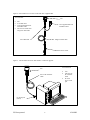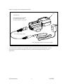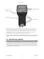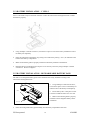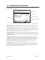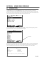
1
YSI Environmental
P u r e
D a t a
f o r
a
H e a l t h y
YSI 650 MDS
Multiparameter Display System
Operations Manual
P l a n e t . ™
YSI Incorporated
2
650 MDS
TABLE OF CONTENTS
SECTION 1 INTRODUCTION
SECTION 2 GETTING STARTED
2.1 UNPACKING
2.2 UNDERSTANDING THE 650 MEMORY
2.3 650 CONFIGURATIONS
2.4 650 FEATURES
2.5 BATTERIES AND CHARGING
2.6 TURNING THE INSTRUMENT ON
2.7 ADJUSTING THE DISPLAY CONTRAST
2.8 USING THE 650 KEYPAD
2.9 CONNECTING TO A SONDE
2.10 UNDERSTANDING THE STATUS BAR
2.11 UPGRADING ECOWATCH FOR WINDOWS SOFTWARE
SECTION 3 SETTING UP THE 650
SECTION 4 SONDE MENU INTERFACE
4.1 INTRODUCTION
4.2 SONDE MENU EXAMPLES
4.3 COMMON OPERATIONS USING 650 SONDE MENU SELECTION
SECTION 5 LOGGING DATA WITH THE 650
5.1 INTRODUCTION AND BASICS OF LOGGING
5.2 LOGGING DATA TO SONDE MEMORY
5.3 LOGGING DATA TO 650 MEMORY
5.4 650 LOGGING – “CANS” AND “CAN’TS”
SECTION 6 MANAGING 650 FILES
6.1 INTRODUCTION
6.2 DIRECTORY
6.3 UPLOAD TO PC
6.4 VIEW FILE
6.5 FILE MEMORY
6.6 DELETE ALL FILES
SECTION 7 UPLOADING DATA FROM SONDES
7.1 INTRODUCTION
7.2 UPLOAD PROCEDURE
SECTION 8 USING GPS WITH THE 650
8.1 SETTING UP THE GPS-650 INTERFACE
8.2 LOGGING GPS READINGS
SECTION 9 USING THE 650 BAROMETER
9.1 PRINCIPLES OF OPERATION
9.2 CALIBRATING THE BAROMETER
9.3 CHANGING BAROMETER UNITS
9.4 LOGGING BAROMETER READINGS
SECTION 10 UPGRADING 650 SOFTWARE
SECTION 11 TROUBLESHOOTING
SECTION 12 FERRITE BEAD INSTALLATION
SECTION 13 650 SAFETY CONSIDERATIONS
SECTION 14 WARRANTY AND SERVICE INFORMATION
SECTION 15 REQUIRED NOTICE
SECTION 16 650 MDS SPECIFICATIONS
YSI Incorporated
3
5
5
6
6
7
10
11
14
15
16
19
21
22
22
25
25
27
29
31
31
33
37
48
50
50
51
52
53
54
54
55
55
55
55
55
56
57
57
57
58
58
59
60
61
62
66
70
70
650 MDS
SAFETY AND EMC CONSIDERATIONS
650 MDS
Before using the 650 MDS, the user should carefully read the caution messages listed below and
should review Section 13 of this manual on Safety Considerations.
CAUTION: The YSI 660 can be used with an optional 6117 rechargeable battery pack that
contains Nickel Metal Hydride Batteries which if misused or not disposed of properly can cause
injury. In addition, the rechargeable battery pack can be charged with a cigarette lighter adapter
that could have safety concerns if not maintained properly. The user MUST read the safety
information concerning the general use of these batteries and their charging which are found in
Section 13 of this manual prior to using the battery pack.
CAUTION: When using the YSI 650 MDS, please be aware that electromagnetic compatibility
(EMC) performance issues may occur under certain conditions, such as when the sonde is exposed to
certain radio frequency fields, fast transients, or electrostatic discharge. If you are concerned with
these issues, consult the Declaration of Conformity that was enclosed with your instrument. Specific
conditions where temporary sensor problems may occur are listed in this document. If you are
unable to locate the Declaration of Conformity that was shipped with your instrument, contact your
local YSI representative, or YSI Customer Service in Yellow Springs, Ohio for a copy of the
document. See Section 14, Warranty and Service Information for contact information. In addition, if
you are using your 650 in a European Community (CE) country, Australia, or New Zealand you MUST
install a clamp-on ferrite bead on your PC interface cable and rechargeable battery pack adapter cable
in order to comply with the Residential, Commercial and Light Industrial Class B Limits for radiofrequency emissions specified in EN55011 (CISPR11) for Industrial, Scientific and Medical laboratory
equipment. See Section 12 for information on installing the ferrite bead assemblies.
TROUBLESHOOTING
The 650 MDS is characterized by sophisticated software that should provided trouble-free operation.
However as with all high-capability software packages, it is always possible that the user will
encounter circumstances in which the instrument does not respond to keypad entry. If this occurs,
the instrument function can easily be restored by removing and then reapplying battery power.
Simply remove either your C-cells or rechargeable battery pack from the battery compartment, wait
30 seconds and then replace the batteries. See Section 2.5 below for battery removal/reinstallation
instructions. See Section 11 below for other troubleshooting information.
YSI Incorporated
4
650 MDS
SECTION 1
INTRODUCTION
The YSI 650 Multiparameter Display System (650 MDS) is a powerful, hand held microcomputer based
instrument that allows the user to display sonde readings, configure sondes, store and recall data, upload
data from sondes and transfer data to computers for analysis and plotting.
Key features of the YSI 650 MDS:
• Completely waterproof case that is submersible to 1 m. Meets IP-67 specification.
• Rugged design with high impact resistance
• Large, non-volatile memory
• Simple cellular phone style keypad.
• Simple intuitive user-interface
• Choice of alkaline batteries or optional rechargeable battery pack
• Fuel gauge display of battery capacity
• User selectable backlight
• Handstrap (standard) or hands free harness (optional) for user comfort
• Optional barometer
• Optional GPS interface
• Compatibility with YSI EcoWatch for Windows data analysis software
• User upgradeable software via the YSI Web page
• CE and Australian C-Tick Compliance.
Partnered with a YSI 6-Series sonde, the 650 will allow the user to easily:
• Display real-time readings from YSI 6-series sondes.
• Log real-time sonde data to internal meter memory with custom site lists.
• Calibrate 6-series sondes.
• Set up 6-series sondes for deployment.
• Upload data from sondes for transfer to PC.
SECTION 2
GETTING STARTED
This section is designed to quickly familiarize you with the hardware and software components of the YSI
650 and its accessories. By the end of Section 2 you will have...
o
o
o
o
o
o
Unpacked the YSI 650 and confirmed that all components are present
Become familiar with the general features and setup configurations of your YSI 650.
Installed batteries in the YSI 650.
Established communication between your 6-series sonde and the YSI 650.
Viewed data from your 6-series sonde on the YSI 650 display.
Learned the basics of making alphanumeric entries from the keypad by setting the YSI 650 clock and
entering an Instrument ID name.
Successful completion of the above list is essential for you to continue on to Section 3, which focuses on the
custom setup of the 650. In subsequent sections, you will learn about how to set up sonde menus via the 650
interface, log data to both sonde and 650 memory, and use the GPS and barometer features of the 650.
YSI Incorporated
5
650 MDS
2.1
UNPACKING
Remove the instrument from the shipping box, being careful not to discard any parts or supplies. Use the
packing list to ensure all items are included, and inspect all assemblies and components for damage. If any
parts are damaged or missing, contact your YSI representative immediately. If you do not know which YSI
dealer you obtained your YSI 650 from, refer to Section 14 of this manual for contact information.
The 650 is offered in four configurations:
•
•
•
•
650-01 – Low memory with no barometer
650-02 – High memory with no barometer
650-03 – Low memory with barometer
650-04 – High memory with barometer
All configurations include the 650 with hand strap and strain relief lanyard installed and the 655174 PC
interface cable for use in data transfer to a PC and software updates from a PC. Make certain that you have
received these two items (650 itself and PC Interface Cable) during the unpacking process.
The following optional accessories are offered for use with the 650.
•
•
•
•
•
•
•
•
•
•
•
6113 Rechargeable Battery Pack Kit with 6116 charger adapter cable, 6114 110 volt wall charger, and
6117 battery pack included
6126 Rechargeable Battery Pack Kit with 6116 charger adapter cable, 6123 universal charger,
European power cable, British power cable, and 6117 battery pack included
6127 Rechargeable Battery Pack Kit with 6116 charger adapter cable, 6123 universal charger,
China/Australia power cord, and 6117 battery pack included
4654 Tripod
614 Ultra Clamp
5085 Hands Free Harness
5065 Form-fitting Case
5081 Hard-sided Case
6117 Extra Rechargeable Battery Pack
6115 GPS Cable for interface with user-supplied GPS unit
616 Cigarette Lighter Charger
If you have ordered any of these accessories with your 650, make certain during the unpacking process that
you have received them.
2.2 UNDERSTANDING THE 650 MEMORY
The 650 is available with two memory options – “low” and “high”.
The less expensive low memory option (650-01 and 650-03) is designed for users who typically use their 6series sondes in sampling applications and store limited data to their logger. The available memory of the
low memory option (ca. 10 kB) will allow the user to log approximately 150 field readings to a single file
in the 650 although the exact logging capability is dependent on the number of parameters active in the 6series sonde. Note also that if multiple files are utilized, the number of logged field readings will be
reduced. In addition, the low memory option will also allow the user to upload small files to the 650 that
have been logged to the internal memory of sondes during Discrete or Unattended sampling studies.
The high memory option (1.5 mB) of the 650 is designed for users who log large files directly to the 650 or
who wish to upload large (or many) files to the 650 from the internal memory of sondes which have been
YSI Incorporated
6
650 MDS
used to log data in Discrete or Unattended sampling applications. For example, with the high memory
option, it would be possible to easily upload the data from 7 sondes, each of which have data files in excess
of 200 kB or approximately 75 days at a 15-minute Unattended sampling interval.
No matter which memory option has been selected, it is important to understand that the memory resident
in the 650 is “Flash”, the same type of memory present in YSI 6-series sondes. Flash memory requires no
battery backup and therefore stored data cannot be lost due to instrument malfunction – a significant
advantage. However, it is not possible to erase individual files from flash memory – to free-up memory,
the user must erase (or format) the entire memory chip. From a practical point of view, this means that,
while named files which are already present in the 650 memory can be “overwritten” during multiple
uploads, the previously written files still occupy space in the memory. These files are in fact designated
“deleted” as will be described in Section 6.5 below. For example, if a file named “TEST” is uploaded
initially with a memory allocation of 50 kB and then is uploaded at a later time (and “overwritten”) with a
memory allocation of 100 kB, the total memory occupied is 150 KB even though only one file with the
designation “TEST” and a file size of 100 kB is shown in the file directory. For this reason, when dealing
with large files, the user may wish to transfer files to a PC immediately after upload and then erase the
entire flash in order to assure that maximum memory is present for subsequent uploads.
The storing of data directly from sondes to the 650 memory, the uploading of data stored in 6-series sondes
to the 650, and the management of these data files are described in detail in Sections 5-7 of this manual.
2.3 650 CONFIGURATIONS
There are a number of ways that you can configure the YSI 650. Below is a list of possible configurations
and corresponding diagrams.
•
•
•
•
650 interfaced to a 6-Series sonde.
650 interfaced to a 6-Series Sonde and a user-supplied GPS unit.
650 interfaced to a PC for data transfer or software upgrade using the PC interface cable
650 with rechargeable battery pack being charged
Figure 1. 650 interfaced to a 6-series sonde.
650
You will need:
•
•
650
6-series sonde
with integral
cable or YSI
field cable
Integral or field cable
with sonde connector
YSI 6-series sonde
YSI Incorporated
7
650 MDS
Figure 2. 650 interfaced to a 6-series sonde with user-supplied GPS.
You will need:
•
•
•
•
650
650
6115 GPS cable
User-supplied GPS unit
with DE-9 cable
YSI 6-series sonde with
integral or field cable
User-supplied GPS unit
with DE-9 cable
6115 GPS cable
Integral or field cable
YSI 6-series sonde
Figure 3. 650 interfaced to PC for data transfer or software upgrade.
You will need:
650
655174 PC Interface
Cable
•
•
•
650
YSI 655174
PC interface
cable
PC with
active serial
port
PC Serial port
(DE-9)
YSI Incorporated
8
650 MDS
Figure 4. Charging of 650 rechargeable battery pack.
650
You will need:
650 with battery pack installed
6116 Charger adapter cable
6114 Wall charger or equivalent
6116 Charger adapter cable
6114 wall charger (shown) or 6123 power supply
The setup of these configurations is described in detail in subsequent sections of this manual. They are
presented here so that your will be able to ascertain if you have all of the parts necessary for your
applications.
YSI Incorporated
9
650 MDS
2.4 650 FEATURES
The key physical features of the 650 display and keypad are shown in the figures below.
650 Front View
Display
Backlight Key
On/Off Key
Arrow Keys
Enter Key
Escape Key
Cellular Phone-Style Keypad
MS-8 Connector
Strain Relief Lanyard
Note that the YSI 650 keypad consists of 20 keys as shown in the diagram above. There are four function
keys, up, down, right and left arrow keys and an alpha/numeric keypad. The top left key that has a green
circle and line,
, is the ON/OFF key. The top right key,
Escape key is labeled
YSI Incorporated
and
, activates the display backlight. The
is the Enter key.
10
650 MDS
650 Back View
Accessory Connections
Barometer Vent
Patch
Battery Lid
Battery Lid Screws
Note that the back of the case contains the battery lid that is attached to the main case with four captive
screws and has three fittings for attachment of the ultraclamp and tripod accessories. In addition, the
battery lid has a hole that is covered with water-impermeable patch for venting of the optional barometer.
CAUTION: The barometer-venting patch is resident on the inside of the battery lid. Removal of or
damage to this patch will result in water leakage into the battery compartment.
The short cord with loop (lanyard) which is attached to the bottom of the case is attached to the strain relief
of the sonde cable. Simply open the D-ring, pass the lanyard loop through the opening, and then close the
D-ring.
2.5 BATTERIES AND CHARGING
The YSI 650 can be powered either with 4 alkaline C cells or a rechargeable NiMH battery pack. With the
C-cell configuration, the user will be able to power a typical YSI 6-series sonde (active dissolved oxygen
and one optical sensor) for approximately 45 hours of continuous operation. The rechargeable battery pack
will allow for about 15 hours of continuous use under these conditions. If the sonde is being powered by its
own internal batteries, the 650 batteries will last much longer. YSI Sondes with internal battery capability
are the 6920, 6600, 600XLM, and 600 OMS.
YSI Incorporated
11
650 MDS
2.5.1 BATTERY INSTALLATION – C CELLS
Four C cells install easily into the back of the 650. Follow the instructions and diagrams below to install
the batteries properly:
•
Using a Phillips or slotted screwdriver, loosen the 4 captive screws on the battery lid and then remove
the battery lid completely.
•
Insert the cells between the battery clips, being sure to follow the polarity (+ and -) as indicated on the
bottom of the battery compartment.
•
Make certain that the gasket is properly installed on the battery lid before reinstallation.
•
Reinstall battery lid and tighten the 4 captive screws securely and evenly using a Phillips or slotted
screwdriver. Do not overtighten.
2.5.2 BATTERY INSTALLATION – RECHARGEABLE BATTERY PACK
The YSI 6113 rechargeable battery pack is self-contained and is easily installed according to the
instructions and diagrams below:
• Using a Phillips or slotted screwdriver,
loosen the 4 captive screws on the battery lid
and then remove the battery lid completely.
Gasket
• Put the battery lid in a safe place so that
it will be available for future use of C cells.
• Make certain that the gasket is properly
installed on the rechargeable battery before
installation.
(4) Screws
•
Insert the rechargeable battery pack assembly into the battery compartment of the 650.
YSI Incorporated
12
650 MDS
•
Tighten the 4 captive screws securely and evenly using a Phillips or slotted screwdriver. Do not
overtighten
2.5.3 BATTERY CHARGING – RECHARGEABLE BATTERY PACK
The 6117 rechargeable battery pack is charged via the MS-8 connector on the bottom of the instrument and
thus the pack must be installed in the 650 for charging. To perform the charging operation, the user will
need to locate the proper power supply (6114 for US/Canada/Japan or 6123 with proper power cord for all
other countries) and the 6116 charger adapter cable which were supplied with your rechargeable battery
pack (6113 for US/Canada/Japan, 6126 for Europe, 6127 for China/Australia). As shown in Figure 4
above, first attach the charger adapter cable to the 650, then insert the barrel connector of the power supply
into the barrel of the adapter cable, and finally plug the power supply into an appropriate AC power outlet.
The pack can be recharged with the 650 either “on “or “off”. However, if the instrument is “on”, the
progress of the charging operation can be viewed in the Status Bar (see Section 2.10 below).
To ensure that you get maximum operational time from the rechargeable battery pack, the user should
follow the procedures below:
1.
2.
3.
4.
5.
6.
Place your display/logger on charge for approximately 2 hours to obtain an 80-90 % regeneration of
battery capacity.
Place your display/logger on charge for approximately 6 hours to get a full charge.
Do not charge the batteries continuously for more than 48 hours.
For long term storage, keep your battery pack between the temperatures of –20 C and 30 C and remove
it from the 650 case.
Do not charge your batteries at temperatures below 0 C or above 40 C.
Do not use or store the battery pack at high temperature, such as in strong direct sunlight, in cars
during hot weather, or directly in front of heaters.
If the above steps are not followed, it may result in a decrease in the operational lifetime of your battery
pack. In addition, pay particular attention to the method of long term storage of the battery pack as is
outlined in the following warning:
CAUTION: If the battery pack/650 will not be used for extended periods of time, the user should remove
the battery pack from the instrument. Failure to do this may result in overdischarge of the pack which can
have a detrimental effect of its lifetime
Note that YSI provides recharge options for many countries in the selection or the 6116, 6126, and 6127
kits. However, it is possible that the power cord options in these kits will not be correct for some users. In
these cases, users should purchase the 6126 or 6127 kit and substitute their local PC type power cord for
the power cord shipped with the kit. This power cord is usually readily available at any local electronics
store.
An optional automotive cigarette lighter charger (YSI 616) is also available for recharging the 650 battery
pack. Note that the user will require the 6116 adapter cable to use the cigarette lighter adapter. Instructions
and diagrams for configuring your cigarette lighter charger and changing fuses are shown below and are
found on the back of the 616 package. The user should save these instructions when unpacking the
accessory and keep them for later reference.
YSI Incorporated
13
650 MDS
To use the device with an American or Japanese vehicle, slide the adapter ring off of the plug. To use the
device with a European vehicle, leave the adapter ring on the plug and position it so the slots on the ring
line up with the plug’s spring clips. To begin charging your battery pack, first plug the barrel connector of
the cigarette lighter charger into the mating end of the 6116 adapter cable. Then attach the MS-8 end of the
6116 adapter cable to the 650. Finally, plug the other end of the cigarette lighter charger into the vehicle’s
lighter socket.
The 616 cigarette lighter charger contains a 2-ampere fast-blow type fuse. If the power cord stops working
properly, unscrew the adapter’s cap, remove the tip, and then pull out and check the fuse. See diagram
above to remove the fuse. If the fuse is blown or you are unsure, replace it with a new 2-amp fast-blow
fuse that is available at electronics stores such as Radio Shack. Reassemble the adapter and securely screw
the cap back onto the adapter body.
After you have installed batteries or the rechargeable battery pack into your 650, you are ready to proceed
to the next sections.
2.6 TURNING THE INSTRUMENT ON
Turn the instrument on by pressing and releasing the on/off button on the top left of the instrument keypad.
The following screen should be displayed.
Main Display
Status Bar
YSI Incorporated
14
650 MDS
Note that the screen is divided into two sections – the “Main Display” at the top and a “Status Bar” at the
bottom. The Main Display will provide access to the 650 and sonde menus and will be used to view sonde
sensor readings in real-time, to configure the 650 and the sonde, to calibrate the sonde sensors, and to log
data to either sonde or 650 memory. The Status Bar will always show the date and time of the 650 clock
(updated in real-time), the remaining battery capacity, the current barometer reading if you have purchased
this option, the GPS readings from a user-supplied GPS instrument, and will indicate whether the menu
being viewed in the Main Display is associated with your sonde or the 650. Additional information about
the Status Bar will be provided in Section 2.10 below.
You may also want to take the instrument into a dark room and, with the instrument turned ON, press the
backlight key which is located at the top right of the keypad. The instrument backlight should illuminate
the LCD so that the display can be read. Pushing the backlight key again will turn the backlight off. The
backlight will power off automatically after two minutes of non-use.
2.7 ADJUSTING THE DISPLAY CONTRAST
The contrast of the 650 display is automatically temperature compensated to provide a proper display under
most field conditions (-10 to 40 C). Some users, however, may wish to alter the display contrast to meet
their own preference. In addition, if the instrument is used at more extreme temperatures, the display is
likely to require some adjustment.
The contrast is easily adjusted by pressing and holding down the backlight key in the upper right of the
keypad and then pressing repeatedly or holding down the up/down arrow keys while observing the display.
Pressing the up arrow while holding down the backlight key increases (darkens) the contrast; pressing the
down arrow under these conditions decreases (lightens) the contrast.
NOTE: The backlight itself will only be activated if the backlight key is pressed and released. You must
hold down the backlight key to adjust the contrast.
YSI Incorporated
15
650 MDS
2.8 USING THE YSI 650 KEYPAD
On/Off
Backlight
Arrows
Escape Key
Enter Key
Alpha/Numeric Keys
Minus/Hyphen (-) Key
Period (.) Key
The 650 keypad allows the user to navigate various sonde and 650 menu selections and to make
alpha/numeric entries into both the 650 and sonde software. The arrow keys are used to select various
options in the menus; the cellular phone-style alpha/numeric keys allow data entry; the Enter key is used to
confirm selections; and the Escape key returns the user to the previous position in the menu structure.
The alpha/numeric keys of the 650 can be used to enter both numbers and letters. For many entries,
however, where only numbers are appropriate, the software automatically allows ONLY numeric entry,
e.g., the letters (ABC) associated with the “2” key cannot be activated. Examples of this type of fixed
numeric entry include setting the clock of the 650 or sonde, entering calibration parameters for sonde
sensors, and changing entries such as DO warm-up time and optical wiper interval in the Sonde
Advanced|Sensor submenu. You will follow an example of this type of entry when you set the 650 clock
in the example below.
When both numeric and alpha entry are appropriate for input, the 650 keypad provides a cellular phonestyle interface for choosing the proper character. As shown in the above diagram, the 2-9 keys can also be
used to input alpha characters. Basically, to activate a particular alpha/numeric character, the user must
press the appropriate key repeatedly until the desired letter or number appears in the display. For example,
to enter an M, press the numeric 6 key once and release. To enter an N, press the numeric 6 key twice in
rapid succession and then release. Lower case letters are also available for input using this basic method.
The following chart shows the alpha/numeric sequence available for each numeric key in the order they
will appear as the key is pressed repeatedly.
YSI Incorporated
16
650 MDS
1 -- 1
2 – ABC2abc2
3 – DEF3def3
4 – GHI4ghi4
5 – JKL5jkl5
6 – MNO6mno6
7 – PQRS7pqrs7
8 – TUV8tuv8
9 – WXYZ9wxyz9
0 -- 0
Using this guide, it can be seen that the character “p” will appear and remain in the display by pressing the
7 key six times in succession. The other characters associated with this key (“P”, “Q”, “R”, “S”, and “7”)
will appear during the repeated pressing of the numeric 7 key. However, only the “p” entry will be retained
after the key is released after the six keystrokes.
After release of the numeric key for approximately 1second, the cursor will automatically scroll to the right
to prepare for the next alphanumeric input. If you make a mistake in the entry, simply return to the
previous character with the left arrow key and reenter the number or letter. After the entry is complete,
press the Enter key to confirm it. You will follow an example of this type of entry when you enter an
Instrument ID name for your 650 in the example below.
To familiarize yourself with the basics of the keypad entry system, follow the instructions below to set the
date and time for your 650 and to enter an Instrument ID:
Turn the instrument on to display the 650 Main menu.
Use the arrow keys to highlight the System setup selection and press the Enter key. A display similar to
the following will appear (Note that the exact format of your displays will depend on the software version):
YSI Incorporated
17
650 MDS
Use the arrow keys to highlight the Date and Time selection and press the Enter key. The following
display will appear:
Highlight the selection for your desired date format and press Enter to confirm it.
Highlight the 4-digit year selection and press Enter to toggle between 2-digit (no check mark present) and
4-digit (check mark present) options.
Highlight the Date selection and press Enter. A cursor will appear over the first number in the date as
shown in the following display.
Enter the proper number from the keypad for the first date digit. Note that when you release the key, the
cursor moves automatically to the next number. Repeat this process until the date is correct. Then press
Enter to confirm the Date entry. Note also that, as described above, since alpha characters are
inappropriate for this entry, only numeric entry is possible.
Highlight the Time selection and press Enter. Repeat the process described above for the Date to enter
your correct local time using the military format. For example, 2:00 PM must be entered as 14:00.
Finally, press the Escape key to return to the System setup menu.
Now highlight the Instrument ID selection and press Enter. The following display will appear.
YSI Incorporated
18
650 MDS
As shown above, enter the designation “YSI 650” using the general instructions outlined above. Start by
pressing the numeric 9 key three times in rapid succession while viewing the characters on the display until
a “Y” appears. After the entry is complete, pause and the cursor will automatically move to the next entry
position. Now press the numeric 7 key four times in succession while viewing the characters on the
display. When an “S” appears, pause and the cursor will move automatically to the next entry position.
Continue with the entries in this way until ID designation is complete. If you make a mistake, you can use
the left arrow key to highlight the flawed entry and correct it. When the entry is complete, press Enter to
confirm it. Note that for this example, where both alpha and numeric entries are appropriate, the user must
press the numeric 2 key 4 times in succession to generate the number 2, as opposed to the previous clocksetting example where a single press of the numeric 2 key generated the number 2.
After completing the above example, press the Escape key repeatedly to return to the 650 Main menu and
then proceed to the next section.
2.9 CONNECTING TO A SONDE
The primary use of the 650 is to interface with YSI 6-series sondes. In this configuration, you will be able
to see data from the sonde sensors in real-time on the 650 display as well as to configure the sonde for your
particular application. In addition, once sonde interface is established, you will be able to easily log data
from the sonde sensors to either the memory of the sonde or the memory of the 650 for later analysis.
The connection between the sonde and the 650 is made via the mating of MS-8 connectors on the standard
YSI field cable and the bottom of the 650 case. To make the connection, hold the 650 in one hand, place
the 650 and cable connectors together, and rotate the field cable connector until engagement occurs. Then
rotate the field cable connector approximately 1-quarter turn until it is fully engaged as evidenced by a
YSI Incorporated
19
650 MDS
“click”. After connecting the sonde to the 650, press the “on” button on the upper left of the 650 keypad to
activate the 650 Main menu as shown below:
Using the arrow keys, highlight the Sonde run entry in the Main 650 Menu and press the Enter key.
Readings from the 6-series sonde sensors will appear on the 650 Main Display in real-time as shown in the
following diagram.
The two windows at the top of the display give the capability of logging the displayed readings to either the
650 (top left) or the sonde (top right) memory and allow the user to activate the wiper on turbidity and/or
chlorophyll probes if they are present in the sonde. Instructions for use of these windows are provided in
subsequent sections of this manual. Note also that there is a disk with rotating segments in the upper right
corner of the display whose movement confirms that the 650/sonde interface is functional.
To return to the 650 Main menu, press the Escape key.
CAUTION: When using the 650 MDS in field applications which are in close proximity to communication
towers and heavy industrial equipment, or which involve very low humidity conditions, the user may
experience problems with logger function. If possible, the user should relocate the sampling site away
from these potential sources of interference. In most cases, symptoms will involve instrument shutdown or
display lockup. These problems can usually be overcome by either simply pressing the on/off key to
reactivate the meter display or by resetting the instrument by removal of battery power as described in
Section 11 of this manual. If symptoms persist after these actions, consult YSI Customer Service for
advice.
YSI Incorporated
20
650 MDS
2.10 UNDERSTANDING THE STATUS BAR
The diagram below shows the various components of the Status Bar of your 650. Each item identified in the
drawing is explained in detail below.
Main Display
Status Bar
Barometer Reading
GPS Reading
Battery Capacity Status
Date and Time
Menu Indicator
2.10.1 Date and Time . This is the date and time for the clock in the 650, set by the user from the System
setup menu as described above. The date and time entries are updated in real-time in the Status Bar.
2.10.2 GPS Reading. This value will be present only if a user-supplied GPS unit with NMEA 0183 format
is connected to the 650 by the optional YSI 6115 cable. The setup of a GPS interface is described in more
detail in Section 8 below. Once properly connected to a GPS instrument, the values displayed in the Status
Bar are updated in real-time as the system is moved from location to location.
2.10.3 Barometer Reading. This value is the current local barometer reading in units selected by the user
in the System setup menu. The value is can be used simply as a meteorological parameter or can be used
in calibration of sonde dissolved oxygen sensors. The barometer reading is NOT corrected to sea level and
is updated in real-time.
2.10.4 Battery Capacity Status. The graphic indicator shows the portion of the battery capacity that is
remaining, either for the 4-C cell configuration or for the optional rechargeable battery pack. If a 6117
rechargeable battery pack is in place, a “NiMH” label will appear as part of the indicator. During charging
of the battery pack, the black portion of the icon will pulse horizontally until charging is complete. In
addition, the entire battery indicator will flash when your batteries are almost exhausted and require
replacement (C-cells) or recharge (optional rechargeable battery pack).
2.10.5 Menu Indicator. This icon is located in the lower right portion of the Status Bar and provides a
guide as to whether the menu on the display of the 650 originates in the sonde or the 650 itself. The icon
shown in the figure above represents a 650 menu; if the menu on the display had originated in the sonde,
the Status bar would display a sonde-like icon as shown below.
YSI Incorporated
21
650 MDS
Sonde Icon
2.11 UPGRADING ECOWATCH FOR WINDOWS SOFTWARE
To utilize the full capability of the 650 MDS, you will need to upgrade your version of EcoWatch for
Windows from the YSI World Wide Web page (www.ysi.com). Access the YSI Environmental Web Page,
select “tech support” from the header, and then “Downloads”. After registration, select the EcoWatch for
Windows upgrade entry and follow the instructions provided. After the upgrade is complete, your
software version (viewed from the EcoWatch toolbar entry Help|About EcoWatch) should be 3.13.00 or
higher.
If you encounter difficulties in the upgrade procedures, contact YSI Customer Service for advice.
After reading the above sections and participating in the simple examples provided, you should be familiar
with the basics of battery installation, keypad and display function, and keypad data entry. Please proceed
to Section 3 where the setup of your 650 is described in detail.
SECTION 3
SETTING UP THE 650
The 650 has a number of features which are user-selectable or which can be configured to meet the user’s
preferences. Most of these choices and selections are found in the System setup selection in the Main 650
Menu. To explore the various setup possibilities of the 650, turn the instrument on, select System setup,
and press Enter. The following display will appear. The second display can be observed by scrolling to
the bottom of the System setup entries with the down arrow.
YSI Incorporated
22
650 MDS
YSI suggests that the user become familiar with the features provided in the list below prior to using the
650 in field applications. Each item is described in some detail below.
3.1 Software version
The software version of your 650 is shown in the first line of the System setup menu. As enhancements
are introduced to the 650, you will be able to upgrade your 650 from the YSI web page. This item will be
used to track those upgrades and will be useful to YSI Customer Service personnel if you have questions
about the function of the instrument.
3.2 Date and time:
As described above in Section 2.8, activate this selection to set the date and time from the 650 keypad.
3.3 Power sonde:
If this choice is active, your 6-series sonde will be powered directly from the 650 batteries. The choice
MUST be active if you are using a sonde with no internal batteries (600QS, 600R, 600XL, or 6820). If
using a sonde with internal batteries (600XLM, 6920, 600 OMS battery version, or 6600), you can extend
the life of your 650 batteries by deactivating this selection. Note that the selection MUST BE OFF in order
to determine the voltage of the internal batteries of sondes – important information for Unattended studies.
3.4 Baud rate to sonde:
This entry allows the user to adjust the baud rate for communication with the sonde. It does not affect
communication for upload of files to a PC. Highlight the entry and press Enter. Then select the baud rate
of choice and press Enter to confirm it. CAUTION: The baud rate for the 650 MUST match that in the
sonde (usually set at 9600) or communication with the sonde will not be possible. Unless you know that
your sonde is set to a baud rate different than 9600, YSI strongly recommends that you leave the baud rate
for the 650 set to the default value of 9600.
3.5 Shutoff Time:
This value represents the number of minutes until the 650 automatically shuts down to save batteries.
Values can be integers from 1 to 15 or enter “0” to disable the shutoff completely.
3.6 Comma radix:
The user can toggle between a period (default) and comma for the radix mark by selecting this item and
pressing the Enter key. If you change your radix mark in the 650, make sure that you also change it to the
same symbol in the sonde Advanced|Setup menu.
YSI Incorporated
23
650 MDS
3.7 ID
Activate this item and Enter choice of instrument identification (limit 11 characters) for your 650 as
described in Section 2.8 above.
3.8 Circuit board SN
This item identifies the serial number of the circuit board resident in your 650. It cannot be changed by the
user.
3.9 Barometer Units:
Highlighting this selection and pressing Enter will activate a display which will allow you to select the
units of barometric pressure which will appear in real-time in the display Status Bar. Highlight the desired
units and press Enter to confirm the selection. This entry will only appear if you have ordered your 650
with the barometer option.
3.10 Calibrate Barometer
You may need to scroll down with the arrow keys to view this selection which allows you to calibrate the
optional barometer to your local barometric pressure. While the barometer has been factory calibrated and
should provide accurate readings on receipt, some sensor drift may occur over time, requiring occasional
calibration by the user. Proceed as follows:
Determine your local barometric pressure. This value is usually obtained from an independent laboratory
barometer. You can also obtain a barometric pressure value from your local weather service. This latter
value has usually been corrected to sea level and therefore must be “uncorrected” before it can be used in
calibration of the 650 barometer. See Section 9 of this manual for details.
Select Calibrate barometer and press Enter. Input the known barometric pressure from the 650 keypad
in the selected units (mm Hg in the following example) and press Enter. Note that in the example, the
barometer output has changed from 733.4 (the previous incorrect value) to 740 (the correct value from your
laboratory barometer). Note also that a value of the approximate barometer offset which occurred during
the calibration (6.3 mm Hg) is present in the display. The offset value is approximate due to the variation
in the tenths of a mm digit of the sensor. This value can be used to return the sensor to its factory
calibration; simply recalibrate the sensor to a new value which is determined by (current value) – (offset).
Note that this entry will only appear if your have ordered your 650 with the barometer option.
NOTE: After initial calibration of the barometer, a file with a name defined by the Circuit Board ID and a
.glp extension (e.g., 00003245.glp) will automatically be generated and stored in 650 memory. Each
additional barometer calibration record for will also be stored. See Section 6.3 below for the transfer of
this file to a computer for viewing and storage.
YSI Incorporated
24
650 MDS
SECTION 4 SONDE MENU INTERFACE
4.1 INTRODUCTION
The Sonde menu selection in the 650 Main menu provides a terminal-like interface simulating the
connection of the sonde to a PC as described in detail in Section 2 of the 6-series manual. Thus, this item
provides access to the entire menu structure of your 6-series sonde software so that you can perform custom
setup in the same way that would be possible if the sonde were attached to a PC.
From the 650 Main Menu, select Sonde menu and press Enter. A display similar (depending on sonde
type and sonde software version) to that shown below will appear:
Sonde Icon
Note that the icon in the lower right of the screen has changed from “meter” to “sonde” indicating that the
menu shown originates in the 6-series sonde. Note also that the 650 display has been designed to be very
similar to that presented on a monitor when a 6-series sonde is attached to a PC as shown below.
------------------Main----------------1-Run
5-System
2-Calibrate
6-Report
3-File
7-Sensor
4-Status
8-Advanced
Select option (0 for previous menu):
YSI Incorporated
25
650 MDS
In fact, the only significant difference between the two interfaces is that, for the PC mode, submenus are
accessed by entering the number associated with the specific item, while for the 650 mode the user must
use the arrow keys to highlight the item and press the Enter key to activate it. Thus, the description of the
6-series sonde menu structure and function which is found in your sonde manual is completely valid as a
reference for setting up your sonde for all types of studies. The menu structure of the sonde is presented in
diagram form below, followed by two examples in Section 4.2 of how to use the 650 Sonde Menu
interface. In addition, brief instructions for frequently performed sonde operation are provided as a
reference in Section 4.3 below.
SONDE MENU FLOW CHART
Sonde
1. Run
1. Conductivity
1. Discrete sample
2. DO %
2. Unattended sample
3. DO mg/L
2. Calibrate
4. Others
1. Directory
3. File
Date and Time
2. Upload
Battery Voltage
4. Status
3. Quick Upload
4. View File
Available Memory
1. Date & Time
Logging Status
2. Comm Setup
5. Quick View File
6. Delete All Files
5. System
3. Page Length
1. (v) Date
4. Instrument ID
2. (v) Time
5. SDI-12 Address
3. (v) Temp, C
7. Test Memory
4. ( ) Temp, F
6. Report
MORE
1. ( v) Temp
7. Sensor
8. Advanced
2. ( v) Cond
1. Cal Constants
3. (v) DO
2. Setup
4. ( ) ISE1 pH
3. Sensor
MORE
4. Data Filter
NOTE: When using the 650, all sonde functions are accessed through the Sonde menu prompt. These
include:
•
•
•
•
•
•
•
•
•
Activating/Deactivating sensors
Setting up the desired Report output
Calibrating the sensors
Changing the sample interval for Discrete Sample studies
Performing file management functions on the memory in the sonde
Checking the Status or System setup of the sonde.
Setting up sondes for Unattended sample deployments.
Setting up sondes for Discrete sample logging studies to sonde memory.
Uploading files from the sonde memory to the 650.
Earlier YSI display/loggers, such as the 610 D and 610 DM, had many of these functions as distinct items
in the display menu structure – a significant difference from the 650.
YSI Incorporated
26
650 MDS
4.2 SONDE MENU EXAMPLES
To become familiar with the 650 Sonde menu function, YSI recommends that the user connect a sonde to
their 650 and proceed through the following two examples of common sonde interface operations.
Example 1: Setting up the Report Output – Activation of the Salinity Parameter
Highlight the Sonde menu selection in the 650 Main menu and press Enter. Then use the arrow keys
highlight the Report selection and press Enter again.
Use the arrow keys to highlight the Salinity selection and then press the Enter key to activate the
parameter as shown by a dot in the open circle. Note that the entire report list can be accessed by
continuing to scroll the highlighting block down with the arrow key. After activation of salinity in the
Report setup of the sonde, press the Escape key twice in succession to return to the Main sonde menu.
Example 2: Calibrating the Dissolved Oxygen Sensor
NOTE: In the following example, it is assumed that the Autosleep RS232 function of your sonde has been
disabled in the sonde Advanced|Setup menu. If Autosleep were active, then the display would indicate a
countdown of the DO warm-up time and calibrate automatically at the end of this time period. See Section
4.3.9 of this manual and Section 2 of your 6-series manual for more information on the Autosleep function.
Place the sonde in the calibration chamber with the dissolved oxygen probe in water-saturated air.
Highlight the Sonde menu selection in the 650 Main menu and press Enter. Then, use the arrow keys to
highlight the Calibration selection and press Enter.
YSI Incorporated
27
650 MDS
Use the arrow keys to highlight the Dissolved Oxygen selection and press Enter. Then, use the arrow keys
to highlight the DO% selection and press Enter.
Use the 650 numeric entry keys and the right/left arrow keys to enter the current local barometric pressure.
Then, press the Enter key and observe the dissolved oxygen reading until stabilization occurs. Make sure
the Calibrate selection is highlighted in upper window.
NOTE: The current barometric pressure as read by your 650 will automatically appear as the default value
if your 650 is equipped with a barometer.
When the dissolved oxygen reading is stable, press the Enter key to confirm the calibration as indicated by
the message “Calibrated” in the header. In addition, the message in the upper window will change from
YSI Incorporated
28
650 MDS
“Calibrate” to “Continue”. Make sure that “Continue” is highlighted and press Enter to return to the DO
calibration menu.
4.3 COMMON OPERATIONS USING THE 650 SONDE MENU
SELECTION
The following section provides brief instructions for carrying out frequently used sonde activities via the
Sonde menu selection of the 650. The instructions do not provide the detail of the examples above,
assuming that the user understands how to navigate the menus with the Enter, Escape, and Arrow keys
and is able to make alpha/numeric entries from the keypad.
4.3.1 Running the sonde in real-time
This function can be accomplished either automatically from the Sonde run selection of the 650 menu or
by using the Sonde menu selection to activate the Run|Discrete Sample submenu of the Main 6-series
menu. If the Sonde run selection is made, data automatically appears on the screen at a sample interval of
approximately 1 second. However, if the user chooses to use the Run function from the sonde menu, the
sample rate can be set to higher values in the Discrete Sample menu. This feature will be described in
detail in Section 5. To Run the sonde from the Discrete sample menu, highlight Start sampling and press
the Enter key.
4.3.2 Setting up a sonde for deployment
Use the 650 Sonde menu selection to access Run|Unattended sample and then proceed with the setup for
the monitoring study as described in detail in Section 2 of the 6-series manual. Use the keypad to set the
sample interval and input file and site names. Then highlight Start logging and press Enter to begin the
Unattended study in which data is logged directly to the sonde memory. Finally, disconnect the 650 and
deploy the sonde.
4.3.3 Uploading data from sondes to the 650
Use the 650 Sonde menu selection to access the sonde File menu and then choose either a Quick upload
(all data in the last file) or Upload (complete or partial data in any sonde file) as described in detail in
Section 2 of the 6-series manual. After the proper selection is made, press Enter and the file will be
transferred automatically to the 650 memory with the 650 display indicating that an upload is in progress.
The uploading of data files from sondes to the 650 is demonstrated in greater detail in Section 7 below.
YSI Incorporated
29
650 MDS
4.3.4 Calibrating sonde sensors
Use the 650 Sonde menu selection to access the sonde Calibrate menu. Once the menu has been
activated, use the arrow keys to highlight a sensor for calibration and follow the instructions on the screen.
Use the keypad to enter numeric values associated with the calibration standards and press Enter to
confirm your input. View the data from each calibration standard in real-time and then highlight the
Calibrate selection in the upper frame. When the output is stable, press Enter to confirm the calibration
point. Then highlight Continue and press Enter to either move to the next calibration point or to finalize
the calibration. See the example in Section 4.2 above for a typical calibration procedure.
NOTE: To return a sensor calibration setup to its factory default setting, access any calibration routine for
that particular sensor which asks for numeric input. However, instead of entering numbers, hold the Enter
key down and press the Escape key. Highlight “yes” and press Enter. This protocol is the equivalent of
entering the command “uncal” from a computer keyboard.
4.3.5 Changing the sonde Sensor setup
Use the 650 Sonde menu selection to access the sonde Sensor menu. Once the menu has been activated,
use the arrow keys to highlight a sensor for activation/deactivation and press Enter to confirm your choice.
4.3.6 Changing the sonde Report setup
Use the 650 Sonde menu selection to access the sonde Report menu. Once the menu has been activated,
use the arrow keys to highlight a sensor for activation/deactivation and press Enter to confirm your choice.
See the example in Section 4.2 above.
4.3.7 Viewing data stored in the sonde
Utilize the 650 Sonde menu selection to access the File menu of the sonde. Highlight the “View file”
selection and press Enter. Select the file that you want to view. Choose Proceed and press Enter to view
the entire file or select the portion of the data that you want to view and then select Proceed and press
Enter to confirm your selection. After data has appeared on the screen, use the arrow keys to select the
particular sensor data that you wish to view.
IMPORTANT: The sonde Quick view file, which is designed to show the last page of data of the last
logged file when the sonde is interfaced to a PC is slightly different for the sonde/650 interface. Making
this selection will indeed show data from the last logged file, but all data (not just the last page) will be
displayed. It is still possible, however, to quickly view the last few logged data points which may be
important in checking a sonde’s current performance in the field. To rapidly move to the end of the file (in
either View file or Quick view file), press and HOLD the down arrow to accelerate the transition to the
final data points. Then use the arrow keys to view the data of interest.
4.3.8 Configuring and setting the sonde clock
Utilize the 650 Sonde menu selection to access the System menu of the sonde. Highlight the Date &
Time selection and press Enter. Use the arrow keys to highlight the preferred date format and press
Enter to confirm your selection. Activate/deactivate the 4-digit year selection, as desired, using the Enter
key to toggle between choices. Finally, set the date and time by highlighting the entries and inputting new
values from the keypad.
4.3.9 Setting the sonde Autosleep configuration
As explained in Section 2 of the 6-series manual, the setup of the Autosleep RS-232 function of the sonde
should be governed by the following rules:
•
•
Unattended sample studies/Remote deployments – Autosleep Active
Discrete sample studies with user present – Autosleep Inactive
The rules are particularly important with regard to the method of dissolved oxygen calibration – automatic
at the Unattended sample interval if Autosleep is Active; manually controlled by the user if Autosleep is
inactive. See Section 2 of the 6-series manual for additional information on the Autosleep function.
YSI Incorporated
30
650 MDS
To set the Autosleep function, utilize the 650 Sonde menu selection to access the Advanced|Setup menu
of the sonde. Use the up/down arrow keys to highlight the Autosleep RS232 selection and toggle the
function on/off with the Enter key until it is correct for your application.
SECTION 5 LOGGING DATA WITH THE 650
5.1 INTRODUCTION AND BASICS OF LOGGING
A primary function of the 650 is to facilitate the storage of field data from 6-series sonde sensors for later
analysis. It is important to understand that sonde sensor data can be logged to two memory locations using a
system consisting of a 650 interfaced with a sonde: (1) memory resident in the sonde and (2) memory resident
in the 650 itself. Different applications may favor one logging choice over another. In addition, data can be
logged either as single points (after the user has verified stabilization) or as a continuous data stream at a fixed
sample interval. No matter where or how the user decides to log field data with a 650/sonde system, the 650
software plays the key role in controlling the process.
When setting up the 650/sonde system for your logging application, it important to realize that the 650 Run
display, from which all logging is initiated can be activated by two methods. The first is to simply highlight
the Sonde run selection from the 650 menu. The second is to use the Sonde menu command from the 650
Main menu to enter the sonde menu structure and then to activate a Discrete sample study. Either of these
methods can be used to log data to both the sonde and the 650. However, for most applications, the latter
method (Run screen from sonde Discrete sample) should be used to activate logging to sonde memory with
the sample interval between logged points in a continuous data stream set from the Discrete sample menu of
the sonde. Likewise, the former method (direct activation of the 650 Run display from the Sonde run
command) should usually be used to activate logging to 650 memory with the sample interval set in the
Logging setup menu of the 650.
NOTE: Logging to sonde memory may not be possible for some older version 600R, 600XL, and 6820
sondes that were purchased prior to September 1999.
The two modes of activating the 650 Run display prior to the logging of data to either sonde or 650 memory
are shown in schematic fashion in the following drawing:
YSI Incorporated
31
650 MDS
Sample Interval
Set in 650
Logging setup
menu
Sample Interval
Set in Sonde
Discrete sample
menu
650 Logging
Window
Sonde Logging
Window
The user should particularly note the two windows in the upper portion of the display above, one designated
“650” and the other “Sonde”. All logging, either to sonde or 650 memory is controlled from these windows.
As indicated, data storage to the 650 is controlled from the upper left logging window. Storage to the sonde
memory is controlled from the upper right logging window. The highlighting cursor associated with the
logging windows can be moved within a particular window using the up/down arrows and toggled from
window to window using the left/right arrows. Note also that, if your sonde contains an optical sensor, it is
possible to activate the probe wiper prior to logging from the Sonde logging window.
While the following sections will show that the logging functions of the 650 have a high degree of flexibility
and capability, from a basic point of view, logging with the 650 is simple:
YSI Incorporated
32
650 MDS
•
Decide if you want to log data continuously, and, if so, determine what sample interval between data
points is appropriate for you study. If you will be logging to 650 memory, highlight the Logging setup
selection from the 650 Main menu, then highlight the Interval selection and set the interval as desired. If
you will be logging to sonde memory, select the 650 Sonde menu and then Run|Discrete sample from
the sonde menu. Set the sample interval and then activate the data display by selecting Start sampling.
•
Select the memory (sonde or 650) in which you want to store your data by toggling between the logging
windows.
•
Highlight the logging method desired – “Log one sample” for a single logged point or “Start logging” to
store a continuous data stream.
•
Press Enter to activate the logging selection.
•
To end the study if a continuous data stream was selected, press Enter with the highlight cursor on the
Stop logging command or press the Escape key.
Sections 5.2 and 5.3 below provide details and real-life examples of logging data to sonde memory and to 650
memory, respectively, using the 650 as the interface.
5.2 LOGGING DATA TO SONDE MEMORY
5.2.1 INTRODUCTION
All YSI 6-series sondes sold since September 1999 have memory present on their internal PCBs. In addition,
all 600XLM, 6920, and 6600 sondes have internal memory, regardless of the date of purchase. Interface of
these sondes to a 650 allows the user to easily store data (either a single point or a continuous stream) to the
sonde memory. If a continuous stream of data is desired, the interval between the stored points is controlled
by the Sample interval in the sonde’s Discrete sample function. The file name under which this data is
stored and the site name associated with the file are also input in the Discrete sample function of the sonde
using the 650 keypad as the input method. When logging to sonde memory, be sure to follow the instructions
above with regard to entering the 650 Run display either directly from the 650 Sonde run menu or indirectly
from the 650 Sonde menu selection to control your sample interval.
The following examples show the setup and implementation of logging to sonde memory using the 650 as the
interface device.
5.2.2 EXAMPLE 1 – SIMPLE SINGLE POINT LOGGING TO SONDE
MEMORY
A user with a 600XL/650 system wants to store data electronically from a single site rather than writing down
the information manually in the field.
To log this data point to the sonde memory, the user highlights the Sonde run selection in the 650 Main
menu and presses Enter to begin data display.
YSI Incorporated
33
650 MDS
The user places the sonde in the water and watches the readings on the 650 display until they are stable.
When stable, the Log one sample selection in the Sonde logging window (upper right) is highlighted as
shown above and the Enter key is pressed. The header changes from “Run” to “Sample logged” to confirm
that the data storage to sonde memory was successful and then returns automatically to the Sonde run
display. The user turns the 650 off and returns to the office to retrieve the data.
The single data point is stored in the sonde memory under the automatically generated file name NONAME1.
The file can be viewed by selecting Sonde menu from the 650 Main menu and pressing Enter.
To view the data on return from the site, the user selects the sonde menu File selection, presses Enter to
confirm the entry, and then highlights theView file selection and presses Enter. Following these instructions
generates a display of the data that is stored in the sonde memory under automatically generated name
NONAME1. Use the right/left arrow keys to scroll horizontally to view all of the data.
The user manually records the data from the site and turns the system off.
5.2.3 EXAMPLE 2 – CONTINUOUS LOGGING APPLICATION TO SONDE
MEMORY
A user wants to carry out a vertical profile of a lake from 0 to 30 feet in order to detect the presence of a
thermocline, and, if identified, to locate its position in the water column. The experiment will involve
lowering a 6920 sonde in 1 foot increments until the bottom of the lake is detected, leaving the sonde at each
depth for 3 minutes to allow the sensor readings to stabilize while logging data continuously. Thus, the user
will generate data over a 90 minute time period (30 increments times 3 minutes per increment). If data were
logged directly to sonde memory at the default 0.5 second sample interval, a very large data file containing
5400 data points would be generated, with little benefit gained from its size.
With this in mind, the user decides to increase the sample interval to 16 seconds, thus greatly reducing the
amount of data in the file with no loss of real resolution. As explained above, the sample interval for logging
to sonde memory is set in the Discrete sample menu of the sonde, and thus the user MUST activate the 650
Run display indirectly using the 650 Sonde menu selection as detailed above.
YSI Incorporated
34
650 MDS
The user attaches the 6920 sonde to a 650. After turning on the 650, the user selects Sonde menu from the
650 Main menu and presses Enter to display the Main sonde menu.
The user then selects Run from the sonde Main menu and Discrete sample from the Run menu, pressing
Enter to confirm each selection.
To set up the desired study parameters, the user uses the 650 keypad to change the Sample interval from 0.5
seconds to 16 seconds and inputs custom file (PROFILE1) and site (WEST LAKE) designations.
The user then highlights Start sampling and lowers the instrument into the water to begin the study. The data
displayed on the screen is updated every 16 seconds. The user then highlights the Start logging selection in
the sonde logging window in the upper right of the display and presses Enter to begin logging data to sonde
memory. The message in the sonde logging window changes to Stop logging, indicating that logging has
successfully been activated.
YSI Incorporated
35
650 MDS
At the end of the 90 minute profile determination, the user either confirms the Stop logging command by
pressing Enter or simply presses the Escape key to return to the sonde Discrete sample menu, highlights the
Close file selection, and confirms the file closing by pressing Enter.
The profile data taken at a 16 second sample interval is now stored in the sonde memory under the file name
PROFILE1. It can be viewed on the 650 display and/or uploaded to the 650 memory or directly to a PC by
accessing the sonde File menu.
5.2.4 SONDES WITHOUT MEMORY
If your sonde is a 600R, 600XL, or 6820 purchased prior to September 1999, it may contain a circuit board
that does not have memory. With sondes of this type, you will not be able to log data to the sonde – only to
the 650 as detailed in the following section. With these no-memory sondes attached to your 650, the Run
display will show a blank Sonde logging window as shown below.
YSI Incorporated
36
650 MDS
5.3 LOGGING DATA TO 650 MEMORY
5.3.1 INTRODUCTION
Even if the sonde in your 650/sonde system has its own memory, it may be more convenient for you to log
data directly to the 650 memory simply because you eliminate the need to upload the data after logging,
i.e., it will already be resident in 650 memory. In addition, logging directly to 650 memory allows you to
log GPS and barometric pressure readings along with sonde sensor data. Barometer and GPS data cannot
be logged to sonde memory. Finally, the file/site list capability associated with the 650 is more powerful
than that of the sonde, allowing you to log data from several sites to a single file. If these applications are
important to you, then it is likely that logging directly to 650 memory should be your first choice.
Naturally, if your sonde is a 600R, 600XL, or 6820 with no memory (pre-1999), then you will be
REQUIRED to log your sonde data directly to the 650.
Before proceeding in this section, be sure that you review Section 5.1 above which describes the basics of
logging with a 650 (either to sonde or to 650 memory).
The following sections will provide details and examples of the flexibility of logging sonde data to 650
memory. The distinction between (a) simple occasional logging with file and site names entered at the
logging site and (b) logging to a more sophisticated file structure where file parameters are entered into a
site list prior to going to the field will be described.
5.3.2 SIMPLE LOGGING TO 650 MEMORY
The term “simple logging” to 650 memory refers to the method of defining file and site names for the
study. In applications of this type, the user inputs new file and site (optional) names for each study at the
time the data is logged.
IMPORTANT: The Use site list selection in the 650 Logging setup menu should be INACTIVE for the
example below which demonstrates simple logging.
A user with a 600XL/650 system wants to store a continuous stream of data electronically for a single site at a
sample interval of 10 seconds between data points. Note that this is a similar example to that in 5.2.2 above,
except that the logging is to 650, rather than sonde, memory and a data stream, rather than a single point, will
be logged.
The first step in this application is to make certain that the sample interval is set correctly for the logging
study. The factory default sample interval of 1 second will therefore need to be changed to 10 seconds.
To set the sample interval, highlight the Logging setup entry in the 650 Main menu and press Enter.
YSI Incorporated
37
650 MDS
Press Enter at the highlighted Interval selection and use the arrow keys to scroll to the right and change the
interval from 1 second to 10 seconds. Confirm the selection by pressing Enter and then press Esc to return to
the 650 Main menu.
Once the sample interval is set correctly in the 650 Logging setup menu, the user simply highlights the Sonde
run selection in the 650 Main menu and presses Enter to begin data display.
The user places the sonde in the water and then highlights the Start logging selection in the 650 logging
window (upper left) and presses Enter. The user is then prompted to enter a Filename and Site description
for the study as shown below.
YSI Incorporated
38
650 MDS
Using the arrow keys, the Filename window is highlighted, the user presses the Enter key and then inputs the
file name (in this case, WEST) from the keypad as shown above. A site name (BLUE LAKE) is then entered
from the keypad by highlighting the Site description window and proceeding as for the File name. Pressing
Enter confirms the Site entry. The user then highlights the OK window and presses Enter to begin logging
the data stream. The header of the 650 logging windows changes to Stop logging to confirm that the data
storage to 650 memory is active and a countdown timer appears at the top of the display to show the exact
moment a point is logged to 650 memory. When the study is complete, the user highlights the Stop logging
selection and presses Enter to terminate logging.
NOTE: For ultimate simplicity, it was not necessary to enter either a file or a site name in the above
application. If the OK window had been highlighted immediately and Enter pressed, a point will be logged
to a file in the 650 memory under the designation NONAME1. It is also possible to input a custom file name,
but not enter a site name and then log the point.
The stream of data is stored in the 650 memory under the file name WEST that was input by the user. The file
can be viewed by selecting File from the 650 Main menu and pressing Enter. Then highlight the View file
selection and then the selected file (WEST), pressing Enter after each entry. The data in the file will be
displayed as shown below. Use the arrow keys to scroll horizontally in order to view all of the data.
Note that, using these same basic guidelines, data could have been logged at another site on the same day with the
user inputting a different site designation (file name and site name) in the field. Data could also have been logged
single points or as a continuous data stream at each site simply by the choice of Log single point or Start
logging, respectively, in the 650 Logging window.
Data can also be appended at later times to existing site designations. However, there is a limitation on
this process: the parameter setup during subsequent logging runs MUST be exactly the same as for
the first entry. For example, if you add a sonde parameter to the Report for the second logging run to a
particular site, you will not be able to append this data to the existing file. If you logged Barometer or
GPS readings to the initial file you will be required to maintain the logging of these files on subsequent
logging runs. If your current parameter setup is different from the one used initially, a “Parameter
Mismatch” screen similar to that shown below will appear when you try to log data to the old site
designation. The screen should help in pinpointing the change in your parameter setup that is causing the
inability to append the file. In the example below, the old parameter setup is shown on the right of the
screen and the new parameter setup is on the left. It is evident that the mismatch occurs in the third line
where salinity from the new setup is “mismatched” with “DO %” from the old setup. The screen thus
shows that salinity has been added to the parameter list between the two logging studies and must be
removed if the original file is to be appended with further data.
YSI Incorporated
39
650 MDS
5.3.3 LOGGING TO 650 MEMORY WITH A SITE LIST
In the example above, you learned how to log data to 650 memory that had file and site designations input
to the logger at the time that the data was logged in the field. It is also possible, and in most cases more
convenient, to place file and site designations into the 650 memory in the office or laboratory before
moving to the field for logging studies. This is particularly true if you are aware of the sites at which you
will be determining water quality data and/or which you will be visiting on a regular basis. The following
section describes how to set up site lists which contain entries designated “Site Designations” that will be
instantly available to the user in the field to facilitate the logging of data in the field with pre-established
naming of files and sites. There are two kinds of Site Designations available for use in Site lists:
•
Site Designations associated with applications where data from a single site is always logged to a
single file. This type is referred to as a “Single-Site Designation” and is characterized by two
parameters – a file name and a site name. Files logged to 650 memory under Single-Site Designations
will be characterized primarily by the File name, but will also have the Site name attached, so that it is
viewable in either the 650 File directory or in EcoWatch for Windows after upload to a PC
•
Site Designations associated with applications where data from multiple sites are logged to a single
file. This type is referred to as a “Multi-site Designation” and is characterized by three parameters – a
file name, a site name, and a site number. Files logged to 650 memory under Multi-site Designations
are characterized by a file name, but not a site name, since multiple sites are involved. However, each
data point has a Site Number attached to it so that the user can easily determine the sampling site when
viewing the data from the 650 File menu or processing the data in EcoWatch for Windows after upload
to a PC.
When reading the following section on the use of the 650 Site list, remember that a Site List is a
compilation of individual entries called Site Designations. Single-Site Designations are used when the
data from a particular location is always logged to the same single file. A Single-Site Designation is
characterized by a unique file name. Multi-Site Designations are used when data from several locations
are logged to a single file. For Multi-site Designations, there will a single File Name with multiple Site
Names and Site Numbers. The following displays show examples of Single and Multi-Site Designations.
Site List
Single-Site Designations
with Different File Names
YSI Incorporated
40
650 MDS
Site List
Multi-Site Designations with
the Same File Name
Note that Site lists containing Single Site Designations are usually input with the designation Store Site
Number INACTIVE in the 650 Logging setup menu. Thus, no site numbers appear in the first Site list
example. Conversely, Site lists containing Multi-Site Designations MUST be input with the Store Site
Number selection ACTIVE as shown in the second example.
As noted above, establishment of either of these two types of Site Designations that are stored in 650
memory in a Site List will allow you to log field data to the 650 memory without entering file/site
information from the 650 keypad in the field at each site. You will easily be able to access previously
entered Site Designation information from this the Site List at each field site and thus simplify your record
keeping and logging procedures. To utilize the full capability of the 650 logging system, you will need to
understand how to set up and use these two types of Site Designations, particularly if you are performing
multiple or replicate logging studies at various field sites. The following discussion and examples should
help you understand how to set up site lists for various applications.
LOGGING OF DATA TO 650 MEMORY FROM SINGLE SITES TO SINGLE FILES – USE OF
SINGLE-SITE DESIGNATIONS IN A SITE LIST
The setup and use of Single-Site Designations will be provided in the following application example:
Water quality data needs to be collected for two sites at the West and East ends of a lake (Blue Lake) at
various time intervals for 30 days. The environmental scientists want all of the data for each site to be in a
separate data file that can be reported from EcoWatch for Windows or from a spreadsheet. The key to this
application is that each physical location will need to be characterized by a different File Name in the Site
Designation.
To establish a site list in the 650 memory for this application, highlight the Logging setup selection in the
650 Main menu and press Enter. The following screen will appear. Make certain that the selection Use
Site list is active to display the full capability of the Logging setup as shown below. To set up a list with
Single-Site Designations the selection Store Site number should be INACTIVE (as shown below) before
proceeding.
YSI Incorporated
41
650 MDS
Note also that if you have purchased a 650 without the barometer option, the selection Store barometer
will not be present. Decide whether or not you want to store GPS and barometer information with your
data file and activate/deactivate the Store Lat and Long and Store Barometer selections appropriately.
Leaving these selections active will occupy memory in the 650 during logging and this factor may be a
consideration if you have purchased a 650 with “Low” memory and you do not really require this
information in your file. Once these selections have been made, highlight the Edit site list selection and
press Enter to display the screen below. Note that you can use the left/right arrows to scroll between the
Filename and Site name selections and that tips about the meaning of these terms are provided at the
bottom of the display depending on the position of the cursor.
To make Site list entries for this application, begin by highlighting the Filename position, pressing Enter
and inputting the file name (WEST, in this case) from the keypad. Press Enter to confirm the entry and the
cursor will automatically move to the right for the entry of a Site name . Enter BLUE LAKE for the site
and press Enter to confirm the entry. The cursor will move automatically to the next Filename entry
position. Now enter EAST for the file name and BLUE LAKE for the site name, pressing Enter after each
entry to confirm. Your site list should appear like that in the following display.
You have now established a site list that will be available in the field for logging of data to two files on
BLUE LAKE -- EAST and WEST. To use this list, you need to first make certain that the entry Use site
list is active in the 650 logging setup. Then travel to the first location, identified by the Filename WEST,
activate the 650 Run display, and then select either a continuous data stream (Start logging) or a single
data entry (Log single point) from the 650 logging window.
YSI Incorporated
42
650 MDS
Then press Enter. When the logging prompt is activated, the site list will automatically appear on the
display and be available for use in your study as shown below. First highlight the WEST file (since you are
at that location) and press Enter to log data to the 650 memory. An indication that the logging was
successful will appear in the 650 logging window. Then move to the next location (EAST), activate the
650 logging function, and repeat the logging process, but this time highlighting the EAST Filename entry.
NOTE: If you want to return to the Edit site list display for changes before logging, use the RIGHT
ARROW KEY to highlight the Configure selection and press Enter. The up/down arrows will only scroll
within the Site list.
The data from the two locations has been logged to the selected files that can be either viewed manually
using the 650 View file menu or uploaded to EcoWatch for Windows from the 650 File menu. This means
that all data for the West and East sites are located in separate files identified by the Filenames WEST and
EAST as shown in the 650 File Directory below.
Details of the files (shown by pressing Enter when the File is highlighted in Directory) are shown below.
Note that the site name (BLUE LAKE) is listed in the file since the data was logged using Single-Site
Designations.
YSI Incorporated
43
650 MDS
These files will remain “open” in 650 memory so that you can return to each location at a future time and
log more data to the file designations WEST and EAST (but see note below). The key for this Site list
setup is that all data logged will be stored in a separate file for each location (WEST and EAST) which
were designated as file names at the site BLUE LAKE.
NOTE CAREFULLY: As described above for non-site list files, there is a limitation on appending data to
existing files: the parameter setup during subsequent logging runs MUST be exactly the same as for the
first entry. For example, if you add a sonde parameter to the Report for the second logging run to a
particular site, you will not be able to append this data to the existing file. If you logged Barometer or
GPS readings to the initial file you will be required to maintain the logging of these files on subsequent
logging runs. If your current parameter setup is different from the one used initially, the Site Designation
for that file will be “grayed-out” in the Site list and will not be available until you adjust your parameter
setup. If you try to log data to the grayed-out file, you will be shown a “Parameter Mismatch” screen
similar to that shown in Section 5.3.2 for non-site list files which will aid in diagnosing the differences in
the parameter setup that is preventing the existing file from being appended with new data
LOGGING OF DATA FROM SEVERAL DIFFERENT SITES TO THE SAME FILE – USE OF A
“MULTI-SITE” LIST
The setup and use of Multi-Site Designations will be provided in the following example which deals with
a different approach to the application in the previous example on Single-Site Designations: Water quality
data needs to be collected for two sites at the West and East ends of a lake (Blue Lake) at various time
intervals for 30 days. In this case, the environmental scientists want all of the data in a single file for
recording keeping convenience. The key to this application is that the Site list will need to contain MultiSite Designations with the same Filename, but with different Site names and Site numbers to
characterize each physical location.
To make Site list entries for this application, highlight the Logging setup selection in the 650 main menu
and press Enter. The following screen will appear. As in the previous Site list setup, make certain that you
have activated/deactivated the Store barometer and Store Lat and Long settings as appropriate for your
application. The real key, however, in configuring the Logging setup display for use with a Multi-site list
is that you MUST make certain that the selection Store Site number is ACTIVE (as shown below) before
proceeding.
YSI Incorporated
44
650 MDS
Then highlight the Edit site list selection and press Enter to display the following screen.
To generate a list of Multi-Site Designations for storing readings from various sites to the same file,
establish two entries in the site list with the same file name (BLUELAKE). The entries will be
differentiated by different Site names (WEST and EAST), and, more importantly, by different Site
Numbers (1 for WEST and 2 for EAST) so that your site list appears as shown in display below.
You have now established a site list that will be available in the field for logging of data from two sites
(WEST and EAST) to a single file (BLUELAKE). To use this list, you need to first make certain that the
entry Use site list is active in the 650 logging setup. Then travel to the WEST site, activate the 650 Run
display and then select either a continuous data stream (Start logging) or a single data entry (Log single
point) from the 650 logging window, and press Enter. When the logging prompt is activated, the site list
will automatically appear on the display and be available for use in your study as shown below. First
highlight the entry with the WEST Site name (since your are at that location) and press Enter to log data
to the 650 memory. An indication that the logging was successful will appear in the 650 logging window.
Then move to the next location (EAST), activate the 650 logging function, and repeat the logging process,
but this time highlighting the EAST Site name entry.
YSI Incorporated
45
650 MDS
NOTE: If you want to return to the Edit site list display for changes before logging, use the RIGHT
ARROW KEY to highlight the Configure selection and press Enter. The up/down arrows will only scroll
within the Site list.
The data for two different sites has now been logged to the single file (BLUELAKE) that can be either
viewed manually using the 650 View file menu or uploaded to EcoWatch for Windows from the 650
File|Upload to PC menu. The Site Number (“1” for the WEST site and “2” for the EAST site) will be
stored with each data point and will be thus be available for identifying where the data was taken. The file
BLUELAKE can be examined by use of the 650 File selection. In the 650 File menu, highlight Directory
and press Enter as shown below. Then press Enter with the cursor on the BLUELAKE file to show the
file details.
Note that there is NO Site name listed for the file BLUELAKE since data from more than one site was
logged to it. Now highlight the View file selection and press Enter to display the data in BLUELAKE as
shown below.
Note that the data from two sites is identified by the Site Number attached to each data record. To index
these numbers to the appropriate locations, the user must consult the Site list by activating Edit site list
from the 650 Logging setup menu. The correlation between site names and numbers is found here,
indicating that Site 1 is WEST and Site 2 is EAST.
YSI Incorporated
46
650 MDS
This file will remain in 650 memory so that you can return to each location at a future time and log more
data to the Site designations WEST and EAST. The key for this site list setup is that all data logged will
be stored in the same file (BLUELAKE) under different Site Numbers for each location (1 for WEST and
2 for EAST).
NOTE CAREFULLY: The same limitation noted above applies for appending the file BLUELAKE with
additional data from these or other sites – the logging setup (sonde parameters, barometer, GPS) must be
identical to that for the initially-stored data. If there has been a change in setup, the Site Designation will
be “grayed-out” in the Site List indicating a parameter mismatch.
5.3.4 EDITING YOUR SITE LIST
The 650 software provides powerful tools for editing your site list. Actions such as inserting (adding) new
entries, deleting existing entries, and moving entries within the list can be carried out easily from the
keypad. Highlight the Edit site list entry in the 650 Logging setup display and press Enter to show the
following screen.
Note that the keystrokes for editing the site list are shown in the bottom of the Main Display. Thus, to
insert (add) a file above the present cursor position, simply highlight the proper entry and press the Right
arrow key while holding down the Enter key as shown in the following example. Note that two sites were
inserted in the initial site list using this method.
The two inserted entries can be moved either up or down in the list by highlighting them and pressing the
Up or Down arrow key while holding down the Enter key or completely deleted by highlighting the entry
and pressing the Left arrow key while holding down the Enter key as shown below.
YSI Incorporated
47
650 MDS
Finally, the user should be aware of a timesaving tip that is displayed when the Filename entry is
highlighted. The tip allows much easier generation of Multi-Site Designations where the Filename is
identical for several files. To “copy” the Filename from the previous file to a new entry below, simply
highlight the new Filename block, press Enter and then enter site names and site numbers. The site list
will show these blanks in the Edit site list mode as shown on the left below, but when the site list is
accessed for logging studies the actual Filename will appear to avoid confusion. This is shown at the right
below. Note that, by using this tip, two new sites have been easily added to the BLUELAKE Multi-site list
with no need to physically enter “BLUELAKE” as the Filename for each new site.
Remember that, when editing your Site list, you will have no effect on the actual files which were
previously logged to 650 memory nor on the data in the files. See Section 6 below.
5.4 650 LOGGING – “CANS” AND “CAN’TS”
The use of the 650 to facilitate the storage of data from YSI 6-series sondes has been described in some
detail in the sections above. Unfortunately, the high levels of capability and flexibility of the 650 logging
function might also be viewed as complexity which, in turn, can confuse some users about how to employ
the 650 in their particular application. This section is designed to help with any confusion that exists by
listing what “can” be done with the 650 logging system and what “can’t” be done.
5.4.1 SUMMARY OF 650 LOGGING CAPABILITIES
WITH A 650/YSI SONDE SYSTEM, THE USER CAN:
•
Log sonde sensor data to either sonde memory (if your sonde is so equipped) or 650 memory.
•
Log data as either a single point or as a continuous data stream.
•
Log data in both single point form and continuous stream form to the same file in 650 or sonde
memory.
YSI Incorporated
48
650 MDS
•
Log continuous data stream data at long or short sample intervals to sonde memory, as long as the
study is started from the Run menu of the sonde.
•
Log continuous data stream data at long or short sample intervals up to 15 minutes to 650 memory
using the Sample interval selection in the Logging setup menu of the 650.
•
Log data from the 650 internal barometer to the memory of the 650.
•
Log data from a user-supplied GPS unit to the memory of the 650, as long as the GPS unit is set up in
NMEA format and has the proper cable.
•
Log data with minimal keypad entry from the 650 display by using default file naming.
•
Assign custom file and site names using the 650 keypad at the logging site.
•
Set up custom site lists in the office or laboratory that are instantly available in the field to simply
file/site management.
•
Set up Site Designations that are characterized by a File Name and a Site Name for simple logging of
data from a single site to a single file.
•
Set up Site Designations that are characterized by a File Name, a Site Name, and a Site number which
correlates with the Site name. These lists allow the logging of data from more than one site to the
same file.
•
Easily view data on the 650 display that has been stored to either sonde or 650 memory.
•
Easily upload data that has been stored in either sonde or 650 memory to a PC for analysis using
EcoWatch for Windows software from YSI.
5.4.2 SUMMARY OF 650 LOGGING LIMITATIONS
WITH A 650/YSI SONDE SYSTEM, THE USER CANNOT:
•
Log GPS and/or barometer data to sonde memory.
•
Log GPS and/or barometer to 650 memory without a sonde attached and the 650 in Run mode. See
Sections 8.2 and 9.4 below.
•
Log data to existing files in 650 memory if the data format does not EXACTLY match that of the data
already in the file. Typical examples of this type of “file mismatch” include:
•
Attempting to append existing data files after changing the parameter list.
•
Attempting to append existing data containing a Site Number to a file that contains data
without Site numbers.
•
Attempting to append existing data containing NO site number to a file that contains data with
Site numbers.
•
Attempting to append existing files containing GPS and/or barometer data after deactivating
the storage of these parameters in Logging setup.
YSI Incorporated
49
650 MDS
•
Delete individual files from 650 or sonde memory. The memory is “flash” and therefore all files must
be deleted in order to regenerate the storage capacity.
•
Enter more than 8 characters for a File name or more than 13 characters for a Site name.
SECTION 6 MANAGING 650 FILES
6.1 INTRODUCTION
This section deals with the management of data that have been placed in 650 memory either through direct
logging from your sonde or from the upload of data stored in sonde memory. A “file” by definition contains
data and is distinct from the Site Designations in a Site list that are used to configure actual data files. For
example, deleting an entry from the site list after points have been logged under this designation will have no
effect on the actual logged data, i.e., the file itself will still be present in 650 memory. Conversely, deleting
data files from the 650 memory will not delete the Site Designations from the Site list. The management of
data stored in the 650 is controlled from the 650 File command; the management of the list of file/site
designations is controlled from the Edit site list command in the 650 Logging setup menu as described in
Section 5.3.4 above. Understanding this distinction will help the user avoid confusion in file and site list
management.
It is also important to remember that, as described in Section 2.2 above, the memory of the 650 is “flash” and
that, while this type of memory has many advantages, its use does impose two limitations on file management.
1.
The files are listed in the order that they are logged to memory and this order cannot be changed.
2.
It is not possible to delete individual files to free up memory. The only way to regenerate the 650
memory is to delete ALL files present, i.e., format the flash.
To proceed with the details of 650 File management, turn the instrument on, highlight the File entry in the 650
Main menu, and press Enter to display the File commands as shown below.
YSI Incorporated
50
650 MDS
6.2 DIRECTORY
Use the arrow keys to highlight the Directory selection in the 650 File menu and press Enter to display the
list of files resident in the 650 memory.
Note that the size of the file is shown in two different ways: (1) the number of samples (logged data points of
several parameters) and (2) the total number of bytes of memory occupied by the file. Highlight the top file
(PROFILE1) and press Enter to generate a display of the details of this file. Press Escape and then highlight
the second file (DEPLOY1) and press Enter to again display information about the file.
For both files, the file name, site name, file size and time of the first and last samples logged are shown. The
information under Interval will identify whether the data were logged by manual control of the system
(Discrete) or to the memory of a sonde set up in an Unattended sampling study. Only for Unattended
sampling studies will the actual sample interval be displayed. When the Interval has the designation
“Discrete”, the time between samples can be determined by viewing the data as described below in Section
6.4.
YSI Incorporated
51
650 MDS
6.3 UPLOAD TO PC
This frequently used command is used to transfer data files resident in the 650 memory (either logged directly
or uploaded from sonde memory) to a PC that is running YSI EcoWatch for Windows software. Once
transferred, the data can be custom configured, plotted, and reported in tabular form using this software
package. The data can also be exported from EcoWatch in spreadsheet compatible form if the user prefers
this method of data analysis and management. In order to carry out the upload of data files to your PC, you
must first connect the 650 to a serial port of your computer via the 655174 PC Interface cable as shown in the
following diagram:
650
655174 PC Interface Cable
Computer with
EcoWatch for
Windows Installed
DE-9
PC
PC Serial
port
Serial
Port
(DE-9)
After the connection is made, run EcoWatch for Windows, click on the sonde icon in the upper toolbar, and
set the Comm port number to match your interface. After this setup procedure, the following screen will be
present on your PC monitor:
YSI Incorporated
52
650 MDS
To transfer data from the 650 to your PC, highlight the Upload to PC selection in the 650 File menu and press
Enter to view a list of the files. Highlight the file that you wish to transfer and press Enter. The 650 and PC
displays will show the progress of the file transfer until completion.
Note that there are three file types (with different extensions) in the above directory: (1) Files with .dat
extensions which are data files logged to either sonde memory of 650 memory and which are in YSI PC6000
format; (2) Files with a .txt extension which are data files logged to sonde memory and then transferred to 650
memory in either ASCII or CDF format; and (3) Files with a .glp extension which are calibration records of
either the sonde sensors or the 650 barometer. For files with a .dat or .txt extension, transfer to a PC using the
Upload to PC command will proceed automatically and retain the file type that is present in 650 memory.
For files with a .glp extension, an additional screen will appear on activating the transfer that gives a choice of
binary, CDF, or ASCII for moving the file to the computer. You currently MUST use either the CDF or
ASCII format for transfer so that the .glp file can be viewed in NotePad or other word processing program.
The binary transfer option is for future YSI upgrades.
After transfer files of all types will be located in the C:\ECOWWIN\DATA subdirectory of your PC hard
drive.
6.4 VIEW FILE
The View file selection in the 650 File menu allows the user to examine the data in files logged or uploaded to
650 memory. Highlight the View file selection and press Enter to display a list of files present. Then
highlight the file of interest and press Enter to view the data on the 650 display.
YSI Incorporated
53
650 MDS
Use the arrow keys to scroll vertically to view more data points with regard to time or horizontally to view
more sensor data within a particular data entry. The vertical and horizontal scroll bars identify your location
within the data file.
6.5 FILE MEMORY
The File memory selection in the 650 File menu allows the user to get a complete picture of how the
memory of the instrument is presently allocated. To view details of the allocation, highlight File memory and
press Enter to display the following screen.
The key number in the File bytes used display is the Free memory listing which can be used to determine
when you need to format the 650 memory (“Delete all files” as described in the next section). The value
under Total memory will reflect whether you purchased a 650 with high or low memory. The top three items
in the display summarize the allocation of the used memory space. In the example above, 6400 bytes are used
in defining the memory directory, 512 bytes are taken up with accessible files, and 0 bytes are taken up in
“deleted” files. As described in Section 2.2 above, “deleted” files arise when the same file is uploaded from a
sonde several times with the file “overwritten”.
There is a lot of information on the File memory display, but the number of greatest importance is the Free
memory value.
6.6 DELETE ALL FILES
Use this selection to remove all files from the 650 memory. Remember that you cannot delete individual files
from flash memory. Highlight the selection and press Enter. Use the arrow keys to confirm that you really
want to delete all files and press Enter.
CAUTION: When you use this command, all data currently stored in the 650 memory will be irretrievably
lost, so make certain that you have transferred all files of interest to your PC before carrying out the
procedure. Note, however, that use of the Delete all files command will have no effect on any Site
Designations which have been entered from the Edit site list selection.
YSI Incorporated
54
650 MDS
SECTION 7 UPLOADING DATA FROM SONDES
7.1 INTRODUCTION
A primary function of the 650 is to serve as an intermediate location for transfer of data stored in deployed 6series sondes to a PC without bringing the sondes back to the base facility. In this application, the user
connects the 650 to the sonde at the deployment site via a standard YSI field cable and, using the proper
keypad commands, transfers the data stored in the sonde to the memory of the 650. The sonde is then
redeployed without disturbing the study and the data transferred to a PC on return to the base facility.
7.2 UPLOAD PROCEDURE
After attachment of the sonde to the 650 with a YSI field cable, turn on the 650, highlight the Sonde menu
selection and press Enter to display the Main sonde menu. Highlight the File selection and press Enter.
NOTE: The upload MUST be made from the File menu of the sonde, not the File menu of the 650.
Select the Upload or Quick upload (last file) and press Enter. Then follow the instructions including
selection of file format – YSI recommends the PC6000 format. Press Enter and the display will indicate that
upload of data from sonde to 650 is in progress as shown below. When the upload is complete, the display
will return to the Sonde File menu.
After the sonde file has been uploaded to the 650, the data is resident in the flash memory of both sonde and
650. Note that, if you choose to upload files from the sonde in CDF or ASCII format, the files will be
characterized by a .txt extension in the 650 Directory and will NOT be viewable on the 650 display. To view
these files, you must first transfer them from the 650 to your PC and then open them in a spreadsheet.
SECTION 8 USING GPS WITH THE 650
8.1 SETTING UP THE GPS-650 INTERFACE
The 650 allows the user to display GPS readings of latitude and longitude from a commercially-available,
user-supplied unit in the Status Bar of the 650 display. The interface of the GPS unit to the 650 is
YSI Incorporated
55
650 MDS
accomplished via the 6115 GPS cable that can be purchased as an optional accessory. Using the 6115 cable,
GPS readings can also be logged to the 650 memory along with sonde sensor readings taken at a particular
geographical location, which can then be relocated for subsequent studies.
The use of the GPS interface is easy, but the user must configure the hardware and software of the GPS unit as
follows before proceeding:
•
•
Consult the user manual of the GPS unit and configure the instrument so that readings in the NMEA 0183
protocol are generated.
Purchase from your GPS manufacturer a cable that connects at one end to the GPS unit and has at its
other end a male DE-9 connector for interface with the YSI 6115 GPS cable.
Once these requirements are met, proceed according to the following instructions, consulting Figure 2 in
Section 2.3 above for assistance:
•
•
•
•
Connect the 6115 GPS cable to the 650 via the MS-8 connector.
Connect the other MS-8 connector of the 6115 GPS cable to the MS-8 connector or your sonde cable.
Attach the male DE-9 connector of the 6115 GPS cable to the mating female connector of your GPS unit.
Turn on the 650 and make certain that appropriate GPS readings are displayed in the upper left corner of
the Status Bar as shown in the following display.
8.2 LOGGING GPS READINGS
To log latitude and longitude readings from a user-supplied GPS unit, the following conditions must be
met:
•
GPS readings can ONLY be logged to 650 memory – the system does NOT support logging to sonde
memory.
•
The GPS readings must be logged to 650 memory from the 650 Run display along with sonde sensor
readings. This means that you must have a sonde attached to your 650 via the 6115 cable in order to
log GPS readings. Logging of GPS readings is not supported without sonde attachment even though
these readings can be viewed in the Status Bar with no sonde attached.
•
If your want to log the GPS readings to 650 memory along with sonde sensor readings at a particular
location, you must make certain that the Store Lat and Long option is active in the Logging setup
menu of the 650.
YSI Incorporated
56
650 MDS
Once these conditions are met, follow the instructions in Section 5.3 above for logging of sonde sensor
readings to 650 memory. The GPS readings will automatically be added to the file at the sample interval
selected for the sonde readings.
GPS readings stored in 650 memory will remain as part of the sensor data file that can be viewed from the
650 display and/or uploaded with the data file for analysis in EcoWatch for Windows. Latitude and
longitude are, however, displayed somewhat differently by the 650 and EcoWatch as noted below:
•
For both display formats, the GPS are indexed relative to the point where the Greenwich Mean Time
line crosses the equator.
•
For the 650 Status Bar, readings are displayed in degrees and then decimal minutes relative to this
point with actual “N” (north), “S” (south), “E” (east) and “W” (west) designations relative to the index
point.
•
When analyzing data in EcoWatch, the user will have the choice of two formats, decimal degrees (e.g.,
47.5400 degrees) or degrees/decimal minutes (e.g., 47 o 32.400’). For EcoWatch, alpha directional
characters (“N”, “S”, “E”, and “W”) are NOT used. Instead, points north and east of the index point
are designated as positive, while points south and west are designated as negative.
These criteria mean that the GPS coordinates of Yellow Springs, Ohio, USA are approximately 39 o 47.33’
latitude and -83 o 54.13’ longitude as read in EcoWatch, but N 39 o 47.33’ W 83 o 54.13’ as displayed by the
650.
SECTION 9 USING THE 650 BAROMETER
9.1 PRINCIPLES OF OPERATION
The optional barometer operates on the strain-gauge principle and is located on the internal PCB of the 650.
To make certain that the barometer is sensing true atmospheric pressure under conditions of temperature and
pressure changes, the interior of the case is vented to the atmosphere with patches of material which are
permeable to air, but impermeable to water. One of these patches is located in the rear section of the case and
the other is attached to the battery lid. The patch on the case rear is not accessible to the user, but the one on
the battery lid can be damaged by abuse. Be certain to identify the location of the patch on the interior of the
battery lid and take care not to puncture it with sharp objects or to peel it away from the plastic. If you suspect
that the venting patch on your battery lid has been damaged, make certain that you do not expose the 650 to
water (either spraying or submersion). Then contact YSI Customer Service as soon as possible for advice.
The 650 barometer reads true barometric pressure and therefore is unlikely to agree with values from your
local weather service which are usually corrected to sea level before being distributed. Note, however, that
the primary purpose of the barometer is for use in calibrating your sonde dissolved oxygen sensor and the
“true” value as shown in the 650 Status Bar is the required parameter for this procedure.
9.2 CALIBRATING THE BAROMETER
The 650 barometer is factory calibrated to provide accurate readings in the 500-800 mm Hg range which will
be useful for dissolved oxygen calibration at most locations. This factory calibration should provide readings
that are useful for dissolved oxygen calibration for many months with no user attention. However, if the user
wishes to either increase the accuracy of the sensor in the local barometric pressure range or to compensate for
YSI Incorporated
57
650 MDS
the small drift associated with any sensor, the 650 provides a single point calibration routine which is accessed
in the 650 System setup menu and is described in Section 3.9 above.
The critical factor in carrying out the single point calibration is the accuracy of the “standard” barometer that
is used to determine the true barometric pressure. Common sources of this “standard” reading are high
quality laboratory barometers (either mercury-based or electronic) and data from your local weather service.
Laboratory barometer readings are usually “true” (uncorrected) values of air pressure and can be used “as is”
for a standard as long as the system is known to be accurate. Weather service readings are usually not “true”,
i.e., they are corrected to sea level, and therefore cannot be used until they are “uncorrected”. An
approximate formula for this “uncorrection” (where the BP readings MUST be in mm Hg) is:
True BP = [Corrected BP] – [2.5 * (Local Altitude/100)]
Overall, the key point to remember in calibration of your barometer is to make certain that your “standard”
reading is correct. If the “standard” is not accurate, you are likely to do more harm than good with your usercalibration.
9.3 CHANGING BAROMETER UNITS
The 650 offers the user a choice of six commonly used units of barometric pressure which can be displayed
in the Status Bar. When received from the factory, the 650 will show values in mm Hg. If the user wants
to change to other units, the selection is found in the 650 System setup menu as shown below. Highlight
the selection and press Enter to show the possible units. Then highlight the unit of choice and press Enter
to activate it. The barometer reading in the Status Bar will automatically change to the newly selected unit.
9.4 LOGGING BAROMETER READINGS
To log barometric pressure readings with the 650, the following conditions (similar to those above for
logging GPS readings) must be met:
•
Barometer readings can ONLY be logged to 650 memory – the system does NOT support logging to
sonde memory.
•
The barometer readings must be logged to 650 memory from the 650 Run display along with sonde
sensor readings. This means that you must have a sonde attached to your 650 in order to log barometer
readings. Logging of barometer readings is not supported without sonde attachment even though these
readings can be viewed in the Status Bar with no sonde attached.
•
If your want to log barometer readings to 650 memory, you must make certain that the Store
Barometer option is active in the Logging setup menu of the 650.
YSI Incorporated
58
650 MDS
Once these conditions are met, follow the instructions in Section 5.3 above for logging of sonde sensor
readings to 650 memory. The barometer readings will automatically be added to the file at the sample interval
selected for the sonde readings.
Barometer readings stored in 650 memory will remain as part of the sensor data file that can be viewed
from the 650 display and/or uploaded with the data file for analysis in EcoWatch for Windows. The
barometric pressure readings are processed as a normal parameter by EcoWatch, with the user having the
ability to change units from the EcoWatch menus. For example, data stored in 650 memory in units of mm
Hg units can easily be converted to readings in mBar after upload.
SECTION 10 UPGRADING 650 SOFTWARE
The 650 software can easily be upgraded from the YSI World Wide Web page (www.ysi.com) . However,
before accessing the Web page, the instrument should be prepared for upgrade by attaching the MS-8 end of
the YSI 655174 PC Interface cable to the 650 and the DE-9 end of the 655174 to a serial port of a PC which
has Internet access as shown below:
650
655174 PC Interface
Cable
Computer
with Internet
Access
DE-9 Serial
Port
Once the setup is complete, access the YSI Web Page and locate the section on software upgrades. Select
the 650 upgrade entry and follow the instructions provided on the Web Page. If you encounter difficulties
in the upgrade procedure, contact YSI Customer Service for advice.
YSI Incorporated
59
650 MDS
SECTION 11 TROUBLESHOOTING
The following sections describes problems which you might encounter when using the 650 MDS and provides
suggestions which might allow the user to overcome the symptom without additional assistance.
PROBLEM
No display is visible after pressing the on/off key.
POSSIBLE SOLUTION
If C cells are used, make certain that they are
installed properly with regard to polarity and that
good batteries are used. If a rechargeable battery
pack is used, place the pack in the instrument and
charge for 30 minutes.
Make certain that (a) the cable is connected properly
between sonde and 650 and (b) that Sonde power is
activated in the 650 System setup menu.
First, attempt to reset the instrument by simply
turning off and then on again. If this fails, remove
battery power from the instrument for 30 seconds and
then reapply power. When using C cells, remove the
battery lid and one of the batteries; when using the
rechargeable battery pack, remove the pack
completely from the instrument. After 30 seconds
replace the battery or battery pack and check for
instrument function.
(1) Make sure that cable is connected properly to
both 650 and sonde; (2) Make certain that you are
accessing the upload routine from the sonde File
menu and NOT from the 650 File menu.
1) Make sure that cable is connected properly to both
650 and PC; (2) Make certain that the proper Comm
port is selected in EcoWatch for Windows.
Make sure Store barometer and Store Lat and
Long are active in 650 Logging setup menu.
There is a parameter mismatch between the current
650 setup and that initially used. Use 650 File view
and the Parameter Mismatch screen to determine the
sonde parameter, barometer, and GPS format of file
already present in memory and readjust the setup to
match that initially used.
Make sure that (a) the cables are attached properly;
(b) that the GPS unit is configured for NMEA 0183
format; (c) that the GPS unit is “locked in” and that
the GPS unit display is showing proper readings.
The battery voltage is low. Change to new C cells or
recharge the 6117 battery pack.
The battery voltage is low. Change to new C cells or
recharge the 6117 battery pack.
No interaction with the sonde occurs when pressing
Sonde run or Sonde menu from the 650 menu.
Instrument software appears to be locked up as
evidenced by no response to keypad entries or
display not changing.
Upload of files to 650 from sonde fails.
Upload of files from 650 to PC fails
GPS and/or barometer data is not stored with sonde
data file.
Site Designations in the Site List are “grayed-out”
and not available for appending files with additional
data. A “Parameter Mismatch” screen is displayed.
GPS data is not shown in Status Bar.
The 650 display flashes and the instrument speaker
makes a continuous clicking sound.
The sonde/650 resets when optical wipers are
activated in the sonde.
If these guidelines and tips fail to correct your problem or if any other symptoms occur, contact YSI Customer
Service for Advice. See Section 8 of the 6-series manual for contact information.
YSI Incorporated
60
650 MDS
SECTION 12 FERRITE BEAD INSTALLATION
WARNING: If you are using your 650 in a European Community (CE) country or in Australia or New
Zealand, you must attach a ferrite bead to the 655174 PC Interface Cable and the 6116 Charger Adapter Cable
in order to comply with the Residential, Commercial and Light Industrial Class B Limits for radio-frequency
emissions specified in EN55011 (CISPR11) for Industrial, Scientific and Medical laboratory equipment.
These ferrite assemblies are supplied as part of cable kits.
To install the beads, follow these steps:
•
Make a small loop (approximately 5 cm in diameter) in the cable near the 650 MS-8 connector.
•
Lay the open ferrite bead assembly under the loop with the cable cross-over position within the cylinder
of the ferrite bead. See the drawing below for assistance.
•
Snap the two pieces of the bead together making certain that the tabs lock securely.
When the installation is complete, the 655174 and 6116 cables should resemble the following schematic
drawings.
YSI Incorporated
61
650 MDS
SECTION 13 650 SAFETY CONSIDERATIONS
IMPORTANT SAFETY INSTRUCTIONS!
SAVE THESE INSTRUCTIONS!
In essence, the most important safety rule for use of the 650 is to utilize the instrument ONLY for
purposes documented in this manual. This is particularly true of the 6117 rechargeable battery pack that
contains nickel metal hydride (NiMH) batteries. The 650 user should be certain to read all of the safety
precautions outlined below before using the instrument.
6113 Rechargeable Battery Pack Safety Information
Restrictions on Usage
1.
Never dispose of the battery pack in a fire.
2.
Do not attempt to disassemble the 6117 battery pack.
3.
Do not tamper with any of the electronic components or the batteries within the battery pack.
Tampering with either the electronic circuitry or the batteries will result in the voiding of the warranty
and the compromising of the system performance, but, more importantly, can cause safety hazards
which result from overcharging such as overheating, venting of gas, and loss of corrosive electrolyte.
4.
Do not charge the battery pack outside the 0-40 C temperature range.
5.
Do not use or store the battery at high temperature, such as in strong direct sunlight, in cars during hot
weather, or directly in front of heaters.
6.
Do not expose the battery pack to water or allow the terminals to become damp.
7.
Avoid striking or dropping the battery pack. If the pack appears to have sustained damage from these
actions or malfunctions after an impact or drop, the user should not attempt to repair the unit. Instead,
contact YSI Customer Service.
8.
If the battery pack is removed from the 650, do not store it in pockets or packaging where metallic
objects such as keys can short between the positive and negative terminals.
Precautions for Users with Small Children
Keep the battery pack out of reach of babies and small children.
YSI Incorporated
62
650 MDS
Danger Notifications – Misuse creates a STRONG possibility of
death or serious injury.
FAILURE TO CAREFULLY OBSERVE THE FOLLOWING PROCEDURES AND
PRECAUTIONS CAN RESULT IN LEAKAGE OF BATTERY FLUID, HEAT GENERATION,
BURSTING, AND SERIOUS PERSONAL INJURY.
1.
Never dispose of the battery pack in a fire or heat it.
2.
Never allow the positive and negative terminals of the battery pack to become shorted or connected
with electrically conductive materials. When the battery pack has been removed from the 650, store it
in a heavy plastic bag to prevent accidental shorting of the terminals.
3.
Never disassemble the battery pack and do not tamper with any of the electronic components or the
batteries within the battery pack. The battery pack is equipped with a variety of safety features.
Accidental deactivation of any of these safety features can cause a serious hazard to the user.
4.
The NiMH batteries in the battery pack contain a strong alkaline solution (electrolyte). The alkaline
solution is extremely corrosive and will cause damage to skin or other tissues. If any fluid from the
battery pack comes in contact with a user’s eyes, immediately flush with clean water and consult a
physician immediately. The alkaline solution can damage eyes and lead to permanent loss of eyesight.
Warning Notifications – Misuse creates a possibility of death or
serious injury
1.
Do not allow the battery pack to contact freshwater, seawater, or other oxidizing reagents that might
cause rust and result in heat generation. If a battery becomes rusted, the gas release vent may no
longer operate and this failure can result in bursting.
2.
If electrolyte from the battery pack contacts the skin or clothing, thoroughly wash the area immediately
with clean water. The battery fluid can irritate the skin.
Caution Notifications – Misuse creates a possibility of mild or serious
injury or damage to the equipment.
1.
Do not strike or drop the battery pack. If any impact damage to the battery pack is suspected, contact
YSI Customer Service.
2.
Store the battery pack out of reach of babies and small children.
3.
Store the battery pack between the temperatures of –20 and 30 C.
4.
Before using the battery pack, be sure to read the operation manual and all precautions carefully. Then
store this information carefully to use as a reference when the need arises.
YSI Incorporated
63
650 MDS
616 Cigarette Lighter Charger Safety Information
1.
This section contains important safety and operating instructions for the 650 cigarette lighter battery
charger (YSI Model 616; RadioShack Number 270-1533E). BE SURE TO SAVE THESE
INSTRUCTIONS.
2.
Before using the 616 cigarette lighter charger, read all instructions and cautionary markings on battery
charger, battery pack, and Model 650.
3.
Charge the 6117 battery pack with the 616 cigarette lighter charger ONLY when the 6117 is installed
in the YSI 650.
4.
Do not expose charger to rain, moisture, or snow.
5.
Use of an attachment not recommended or sold by the battery charger manufacturer may result in a
risk of fire, electric shock, or injury to persons.
6.
To reduce risk of damage to cigarette lighter and cord, pull by cigarette lighter rather than cord when
disconnecting charger.
7.
Make sure that the cord is located so that it will not be stepped on, tripped over, or otherwise subjected
to damage or stress.
8.
Do not operate charger with damaged cord or cigarette lighter connector – replace it immediately.
9.
Do not operate charger if it has received a sharp blow, been dropped, or otherwise damaged in any
way; contact YSI Customer Service.
10. Do not disassemble charger other than to change the fuse as instructed. Replace the part or send it to
YSI Product Service if repair is required. Incorrect reassembly may result in a risk of electric shock or
fire.
11. To reduce risk of electric shock, unplug charger before attempting any maintenance or cleaning.
Turning off controls will not reduce this risk.
650 Water Leakage Safety Information
The 650 has been tested and shown to comply with IP67 criterion, i.e. submersion in 1 meter of water for
30 minutes with no leakage into either the battery compartment or the main case. However, if the
instrument is submersed for periods of time in excess of 30 minutes, leakage may occur with subsequent
damage to the batteries, the rechargeable battery pack circuitry, and/or the electronics in the main case.
If leakage into the battery compartment is observed when using alkaline C cells, remove batteries, dispose
of batteries properly, and dry the battery compartment completely, ideally using compressed air. If
corrosion is present on the battery terminals, contact YSI Customer Service for instructions.
If leakage into the battery compartment is observed when using the 6117 rechargeable battery pack,
remove the battery assembly and set aside to dry. Return the battery pack to YSI Product Service for
YSI Incorporated
64
650 MDS
evaluation of possible damage. Finally dry the battery compartment completely, ideally using compressed
air. If corrosion is present on the battery terminals, contact YSI Customer Service for instructions.
CAUTION: If water has contacted the rechargeable battery pack, do not attempt to reuse it until it has
been evaluated by YSI Product Service. Failure to follow this precaution can result in serious injury to the
user.
If it is suspected that leakage into the main cavity of the case has occurred, remove the batteries
immediately and return the instrument to YSI Product Service for damage assessment.
CAUTION: Under no circumstances should the user attempt to open the main case.
YSI Incorporated
65
650 MDS
SECTION 14 WARRANTY AND SERVICE INFORMATION
All versions of the 650 are warranted for three years against defects in workmanship and materials when
used for its intended purposes and maintained according to instructions. Damage due to accidents, misuse,
tampering, or failure to perform prescribed maintenance is not covered. Within the warranty period, YSI
will repair or replace, at its sole discretion, free of charge, any product that YSI determines to be covered
by this warranty.
To exercise this warranty, write or call your local YSI representative, or contact YSI Customer Service in
Yellow Springs, Ohio. Send the product and proof of purchase, transportation prepaid, to the Authorized
Service Center selected by YSI. Repair or replacement will be made and the product returned transportation
prepaid. Repaired or replaced products are warranted for the balance of the original warranty period, or at
least 90 days from date of repair or replacement.
LIMITATION OF WARRANTY
This Warranty does not apply to any YSI product damage or failure caused by (i) failure to install, operate
or use the product in accordance with YSI’s written instructions, (ii) abuse or misuse of the product, (iii)
failure to maintain the product in accordance with YSI’s written instructions or standard industry
procedure, (iv) any improper repairs to the product, (v) use by you of defective or improper components or
parts in servicing or repairing the product, or (vi) modification of the product in any way not expressly
authorized by YSI.
THIS WARRANTY IS IN LIEU OF ALL OTHER WARRANTIES, EXPRESSED OR IMPLIED,
INCLUDING ANY WARRANTY OF MERCHANTABILITY OR FITNESS FOR A PARTICULAR
PURPOSE. YSI’s LIABILITY UNDER THIS WARRANTY IS LIMITED TO REPAIR OR
REPLACEMENT OF THE PRODUCT, AND THIS SHALL BE YOUR SOLE AND EXCLUSIVE
REMEDY FOR ANY DEFECTIVE PRODUCT COVERED BY THIS WARRANTY. IN NO EVENT
SHALL YSI BE LIABLE FOR ANY SPECIAL, INDIRECT, INCIDENTAL OR CONSEQUENTIAL
DAMAGES RESULTING FROM ANY DEFECTIVE PRODUCT COVERED BY THIS WARRANTY.
YSI Incorporated
66
650 MDS
AUTHORIZED SERVICE CENTERS
INTERNATIONAL
YSI Incorporated • Repair Center • 1725 Brannum Lane • Yellow Springs, Ohio • 45387 • Phone: (937)
767-7241• E-Mail: [email protected]
Hydrodata Services (UK) Ltd. • Unit 8 • Business Centre West • Avenue One • Letchworth • Herts SG6
2HB • UK • Phone: (44-1462) 673581 • Fax: (44-1462) 673582 • E-mail: [email protected]
YSI Nanotech • Kaizuka 1-15-4, Kawasaki-Ku • Kawaskaki City • Japan • 210-0014 • Ph: 011-814-42220009 • Fax: 011-81-44-221102 • E-mail: [email protected]
Hoskin Scientific • 4210 Morris Drive • Burlington, ONT., L7L 5L6 • Canada • Ph: 905-333-5510 • Fax:
905-333-4976
UNITED STATES SERVICE CENTERS
OHIO
YSI Incorporated • Repair Center • 1725 Brannum Lane • Yellow Springs, Ohio • 45387 • Phone: (800)
765-4974 • (937) 767-7241• E-Mail: [email protected]
CALIFORNIA
EQUIPCO Sales and Service • 1110 Burnett Avenue, Suite D • Concord, CA • 94520 • Phone: (800)5505875 • Fax: (510)674-8655
COLORADO
Ted D. Miller Associates, Inc. • 2525 S. Wadsworth Blvd., Suite 300 • Lakewood, CO • 80227 • Phone:
(303) 989-7737 • Fax: (303) 989-8875 • E:mail: [email protected]
MISSISSIPPI
C.C. Lynch & Associates, Inc. • P.O. Box 456 • 300 Davis Street • Pass Christian, MS • 39571 Phone:
(800) 333-2252 • (228) 452-4612 • Fax (228) 452-2563
YSI Incorporated
67
650 MDS
CLEANING INSTRUCTIONS
NOTE: Before they can be serviced, equipment exposed to biological, radioactive, or toxic materials must
be cleaned and disinfected. Biological contamination is presumed for any instrument, probe, or other device
that has been used with body fluids or tissues, or with wastewater. Radioactive contamination is presumed
for any instrument, probe or other device that has been used near any radioactive source.
If an instrument, probe, or other part is returned or presented for service without a Cleaning Certificate, and
if in our opinion it represents a potential biological or radioactive hazard, our service personnel reserve the
right to withhold service until appropriate cleaning, decontamination, and certification has been completed.
We will contact the sender for instructions as to the disposition of the equipment. Disposition costs will be
the responsibility of the sender.
When service is required, either at the user's facility or at YSI, the following steps must be taken to insure
the safety of our service personnel.
F In a manner appropriate to each device, decontaminate all exposed surfaces, including any containers.
70% isopropyl alcohol or a solution of 1/4 cup bleach to 1-gallon tap water are suitable for most
disinfecting. Instruments used with wastewater may be disinfected with .5% Lysol if this is more
convenient to the user.
F The user shall take normal precautions to prevent radioactive contamination and must use appropriate
decontamination procedures should exposure occur.
F If exposure has occurred, the customer must certify that decontamination has been accomplished and
that no radioactivity is detectable by survey equipment.
F Any product being returned to the YSI Repair Center, should be packed securely to prevent damage.
F Cleaning must be completed and certified on any product before returning it to YSI.
YSI Incorporated
68
650 MDS
PACKING INSTRUCTIONS
F
F
F
F
F
Clean and decontaminate items to insure the safety of the handler.
Complete and include the Cleaning Certificate.
Place the product in a plastic bag to keep out dirt and packing material.
Use a large carton, preferably the original, and surround the product completely with packing material.
Insure for the replacement value of the product.
Cleaning Certificate
Organization
Department
Address
City
State
Country
Model No. of Device
Zip
Phone
Lot Number
Contaminant (if known)
Cleaning Agent(s) used
Radioactive Decontamination Certified?
(Answer only if there has been radioactive exposure) Yes
No
Cleaning Certified By
Name
YSI Incorporated
Date
69
650 MDS
SECTION 15 REQUIRED NOTICE
The Federal Communications Commission defines this product as a computing device and requires the
following notice.
This equipment generates and uses radio frequency energy and if not installed and used properly, may cause
interference to radio and television reception. It has been type tested and found to comply with the limits for a
Class A or Class B computing device in accordance with the specification in Subpart J of Part 15 of FCC Rules,
which are designed to provide reasonable protection against such interference in a residential installation.
However, there is no guarantee that interference will not occur in a particular installation. If this equipment
does cause interference to radio or television reception, which can be determined by turning the equipment off
and on, the user is encouraged to try to correct the interference by one or more of the following measures:
•
Reorient the receiving antenna
•
Relocate the computer with respect to the receiver
•
Move the computer away from the receiver
•
Plug the computer into a different outlet so that the computer and receiver are on different branch circuits.
If necessary, the user should consult the dealer or an experienced radio/television technician for additional
instructions. The user may find the following booklet, prepared by the Federal Communication, helpful: “How
to Identify and Resolve Radio-TV Interference Problems”. This booklet is available from the U.S. Government
Printing Office, Washington, D.C. 20402, and Stock No. 0004-000-00345-4.
SECTION 16 650 MDS SPECIFICATIONS
Resistance to Water Leakage: IP 67 for both the standard alkaline battery configuration and for the
rechargeable battery pack option.
Operating Temperature Range for Visible Display: -10 to 60 Degrees Celsius
Storage Temperature Range: -20 to 70 Degrees Celsius
Dimensions: 9.13 inches long by 4.75 inches wide by 2.25 inches deep
Weight with 4 Alkaline C cells and no attached sonde or cable: Approximately 2.1 lbs.
(960 g).
Display: ¼ VGA; LCD with 320 by 240 pixels with backlight
Connector : MS-8; Meets IP 67 specification
Standard Battery Configuration:
4 Alkaline C Cells with detached battery cover
Optional Battery Configuration:
Nickel Metal Hydride Battery Pack with attached battery cover and 110 volt charger
YSI Incorporated
70
650 MDS
Battery Life :
Approximate battery life for typical sampling applications with 4 alkaline C cells – 3 hours of
“on” time per day for 0.5 month (10 working days) with the meter powering a 6600 sonde with all
probes active.
Approximate battery life for typical sampling applications with rechargeable battery pack – 3
hours of “on” time per day for 0.2 months (4 working days) with the meter powering a 6600 sonde
with all probes active. Battery capacity restored completely with a 6-hour charge and charged to
approximately 85 % with a 2-hour charge.
Barometer:
Range: 500 to 800 mm Hg
Resolution: 0.1 mm Hg
Accuracy: +/- 3 mm Hg within +/- 15 C of the calibration temperature
Communication Protocol:
RS-232 to all sondes and for data transfer to PC and for software updates
GPS via Y-cable – NMEA 0183
Standard Backlight Feature: 4 LEDs illuminating LCD
Keyboard: 20 keys including Meter On/Off, Backlight On/Off, Enter, Escape, 10 Number/Letter Entry
Keys, 2 Vertical arrow keys, 2 Horizontal arrow keys, 1 minus/hyphen entry key, 1 decimal point/period
key.
YSI Incorporated
71
650 MDS
1700/1725 Brannum Lane
Yellow Springs, Ohio 45387 USA
(800) 765-4974 (937) 767-7241
FAX: (937) 767-9320
Website: http://www.ysi.com
E-mail: [email protected]
Item # 655228
Drawing # A655228
Revision B
August 2001