1
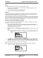
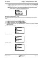
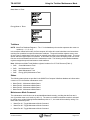
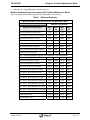
Last Updated: 02-November-2009 TB-980701E Technical Bulletin, Using the Totalizer Maintenance Mode OMNI FLOW COMPUTERS, INC. 12620 West Airport Boulevard, Suite 100 Sugar Land, Texas 77478 United States of America Phone-281.240.6161 Fax: 281.240.6162 www.omniflow.com 52-0000-0010/Rev E Page 1 of 9 TB-980701E Using the Totalizer Maintenance Mode NOTE: User Manual Reference - This Technical Bulletin complements the information contained in Revisions 22, 23, 24, 26, and 27. Totalizer Maintenance Mode – This mode allows the operator to verify meter run calculations by measuring meter run flow rate (gross, net, mass, or energy) without impacting the custody transfer totals) Table of Contents Scope ............................................................................................................................................3 Abstract .........................................................................................................................................3 Procedure to Start and End Maintenance Mode ...........................................................................3 Maintenance Mode Flow Rate and Totalizer Resolutions .............................................................4 Displaying the Maintenance Totals ...............................................................................................5 Totalizers.......................................................................................................................................6 Status ............................................................................................................................................6 Maintenance Mode Command ......................................................................................................6 Modbus Database Points Associated with Totalizer Maintenance Mode......................................7 52-0000-0010/Rev E Page 2 of 9 TB-980701E Using the Totalizer Maintenance Mode Scope The Maintenance Mode feature applies to the following application revisions: 24.74+ Turbine / Positive Displacement / Coriolis Liquid Flow Metering Systems with K Factor Linearization (metric units only) 23.74+/27.74+ Office/Turbine Gas Flow Metering System 22.74.30/26.74.04 Turbine Gas Flow Metering System Abstract The purpose of maintenance mode function is to allow operators to verify meter run calculations. This function measures meter run flow rate (gross, net, mass, and also energy in gas firmware applications) without impacting the overall operation of the custody transfer totals. When in the maintenance mode, the flow measured by the target meter run will not be accumulated in the meter run and/or station totalizers used for normal operation. Furthermore, any D/A outputs configured to output flow rate will not be impacted. While the specific meter is in the maintenance mode, the meter will display zero (0) flow in all the non-maintenance mode displays. Procedure to Start and End Maintenance Mode The maintenance mode function requires a technician Level '1' password. The following is the required procedure to Start and End the Maintenance Mode: 1. Enter a positive value for ‘low flow cutoff’ or ‘active frequency’ (refer to “Meter Run Setup” in Volume 3 of the User Manuals). A positive non-zero entry must be made to ensure that the meter active flag operates correctly at zero (0) flow. 2. Shutdown the meter (flow rate = Zero). 3. In the display mode, press [Alpha Shift] [Diag] [Meter] [n] [Enter]. The OMNI LCD screen will display: NOTE: Maintenance Mode Active/Inactive – If there is a ‘Y’ next to ‘Maintenance Mode’ in the display, then the mode is active. The maintenance mode is inactive when an ‘N’ is displayed. METER #1 MAINTENANCE Maintenance Mode N Reset Maint Totals Toggle Maint Mode _ 4. Press [] (down arrow key) to place the cursor at ‘Toggle Maint Mode’ and press [Alpha Shift] [Y] [Enter]. Depending on the maintenance mode status, the OMNI will toggle the mode. If the maintenance mode is active, then this step will end or “turn off” the mode; and vice versa. You will be prompted for the password. The LCD screen will display: NOTE: Configuration Settings – The maintenance mode uses current flow computer configuration settings; i.e., additional configuration entries are not required. METER #1 MAINTENANCE Maintenance Mode N Reset Maint Totals Password _ 52-0000-0010/Rev E Page 3 of 9 TB-980701E 5. Using the Totalizer Maintenance Mode Type the Level 1 password and press [Enter]. The OMNI LCD screen will display a screen similar to the following: METER #1 MAINTENANCE Maintenance Mode Y Reset Maint Totals Toggle Maint Mode _ NOTE: When the maintenance mode starts after selecting the type of measurement (gross net, mass or energy), the flow rate and totalized flow are zero. To end (deactivate) the totalizer maintenance mode, repeat bullet steps two (2) and five (5). Maintenance Mode Flow Rate and Totalizer Resolutions After a RAM reset, the Maintenance Mode Flow Rate and Totalizer resolutions are automatically defaulted to the same settings as the normal (i.e. non-Maintenance mode) flow rates and totalizer settings. The following is the required procedure to Set or Change the Maintenance Mode Flow Rates and Totalizer resolution settings without affecting the normal mode flow rate and totalizer settings: You should ensure that you have stopped the Maintenance Mode by following the procedures in the previous section titled “Procedure to Start and End Maintenance Mode”. NOTE: Maintenance Mode Active/Inactive - If there is a ‘Y’ next to ‘Maintenance Mode’ in the display, then the mode is active. The maintenance mode is inactive when an ‘N’ is displayed. METER #1 MAINTENANCE Maintenance Mode N Reset Maint Totals Toggle Maint Mode _ 1. From the Display mode, press [Alpha Shift] [Diag] [Meter] [Enter]. The LCD screen will display: MAINTENANCE MODE Resolution Gro Tot Resolution Net Tot Resolution MassTot Resolution Eng Tot Resolution GroFlow Resolution NetFlow Resolution MasFlow Resolution EngFlow 0 0 0 0 0 0 0 0 3. Place the cursor on each of the settings to change the resolution. Each of the totalizers and flow rates can be set independently from zero (0) to three (3) places past the decimal. The number of digits wide for the totalizers will be either eight (8) or nine (9) digits according to the setting configured in the Password menu of the flow computer for the normal totalizers. 52-0000-0010/Rev E Page 4 of 9 TB-980701E Using the Totalizer Maintenance Mode 4. To reset the current totals for an individual meter run, from the Display mode, press [Alpha Shift] [Diag] [Meter] [n] [Enter] and scroll down to the ‘Reset Maint Totals’ prompt and press [Alpha Shift] [Y] [Enter]. NOTE: When the maintenance mode starts after selecting the type of measurement (gross net, mass or energy), the flow rate and totalized flow are zero (0). METER #1 MAINTENANCE Maintenance Mode N Reset Maint Totals Y Toggle Maint Mode Displaying the Maintenance Totals In the display mode, select the displays you want by entering the corresponding key press sequence as follows: For Gross Flow Maintenance Totals, press [Meter] [n] [Gross] For Net Flow Maintenance Totals, press [Meter] [n] [Net] For Mass Flow Maintenance Totals, press [Meter] [n] [Mass] For Energy Flow Maintenance Totals (gas applications only Revisions 23.73+ and 27.72+), press [Meter] [n] [Energy] The OMNI LCD screen will display: MaintenanceMode am³h Meter 1 0 MaintenanceMode am³ Meter 1 0 Gross Meter ‘N’ Enter: MaintenanceMode am³h Meter 1.. 0 MaintenanceMode am³ Meter 1 0 Net Meter ‘n’ Enter: MaintenanceMode nm³h Meter 1 0 MaintenanceMode nm³h Meter 1 0 52-0000-0010/Rev E Page 5 of 9 TB-980701E Using the Totalizer Maintenance Mode Mass Meter ‘n’ Enter: Maint Flow tonnes/hr Meter 1 0 Maint Total tonnes Meter 1 0 Energy Meter ‘n’ Enter: MaintEnergy flowrate Meter 1 0 Maintenance energy Meter 1 0 Totalizers NOTE: Meter Run Database Registers – The “n” in the database point number represents the meter run number (n = 1, 2, 3, or 4). In the totalizer maintenance mode, the flow computer will realize all normal calculations and accumulate resulting flow quantities into special maintenance totalizers. The special totalizer registers reset to zero (0) upon entry to maintenance mode or can be manually reset while in the maintenance mode. This reset will not affect the regular meter run totalizers. In this mode, the LCD screen will display meter run current flow rate and accumulated flow rate for the maintenance mode. The following are the Modbus database registers assigned as special maintenance mode totalizers. Note: Maintenance Mode Totals Modbus registers introduced in v27.74.30 firmware (Table 1). 5n92 Gross Maintenance Total 5n93 Net Maintenance Total 5n94 Mass Maintenance Total 5n95 Energy (NSV) Maintenance Total Status The following status points are provided in the OMNI Flow Computer’s Modbus database to indicate when a meter run is in the totalizer maintenance mode: Meter Run #1 - Maintenance Mode Status Meter Run #2 - Maintenance Mode Status Meter Run #3 - Maintenance Mode Status Meter Run #4 - Maintenance Mode Status Maintenance Mode Command The maintenance mode function can be activated/deactivated remotely, providing that the flow rate is zero (0) and the meter run is inactive (1n05 = 0). The meter run totalizer maintenance mode is activated by setting one or all the following Modbus database points to '1'; the mode will be ended by writing '0' to these same database points: Meter Run #1 - Toggle Maintenance Mode Command Meter Run #2 - Toggle Maintenance Mode Command Meter Run #3 - Toggle Maintenance Mode Command 52-0000-0010/Rev E Page 6 of 9 TB-980701E Using the Totalizer Maintenance Mode Meter Run #4 - Toggle Maintenance Mode Command Modbus Database Points Associated with Totalizer Maintenance Mode Table 1 comprises the database registers for the maintenance mode function. Table 1. Database Registers MODBUS DATABASE POINTS ASSOCIATED WITH THE MAINTENANCE MODE Database Point Number Database Point Description Meter #1 Meter #2 Meter #3 Meter #4 Meter Run Maintenance Mode Status 1197 1297 1397 1497 Previous Batch ‘N’ Maintenance Ticket Flag 2139 2239 2339 2439 Maintenance Ticket (0=No, 1=Yes) 3109 3209 3309 3409 Gross Maintenance Mode Totalizers 5192* 5292* 5392* 5492* Net Maintenance Mode Totalizers 5193* 5293* 5393* 5493* Mass Maintenance Mode Totalizers 5194* 5294* 5394* 5494* Energy (NSV) Maintenance Mode Totalizers 5195* 5295* 5395* 5495* Maintenance Mode Command 2737 2738 2739 2740 Note: The following Modbus registers were introduced in v27.74.20 firmware Maintenance Mode Gross Flow Rate 18575 18675 18775 18875 Maintenance Mode Net Flow Rate 18576 18676 18776 18876 Maintenance Mode Mass Flow Rate 18577 18677 18777 18877 Maintenance Mode Energy Flow Rate 18578 18678 18778 18878 # Dec. Places - Maint Mode Gross Totals 13612 13612 13612 13612 # Dec. Places - Maint Mode Net Totals 13613 13613 13613 13613 # Dec. Places - Maint Mode Mass Totals 13614 13614 13614 13614 # Dec. Places - Maint Mode Energy Totals 13615 13615 13615 13615 # Dec. Places - Maint Mode Gross Flow Rate 13616 13616 13616 13616 # Dec. Places – Maint Mode Net Flow Rate 13617 13617 13617 13617 # Dec. Places - Maint Mode Mass Flow Rate 13618 13618 13618 13618 # Dec. Places - Maint Mode Energy Flow Rate 13619 13619 13619 13619 Maint Mode Gross Total 15536 15636 15736 15836 Maint Mode Net Total 15537 15637 15737 15837 Maint Mode Mass Total 15538 15638 15738 15838 52-0000-0010/Rev E Page 7 of 9 TB-980701E Using the Totalizer Maintenance Mode MODBUS DATABASE POINTS ASSOCIATED WITH THE MAINTENANCE MODE Database Point Number Database Point Description Meter #1 Meter #2 Meter #3 Meter #4 Maint Mode Energy Total 15539 15639 15739 15839 Maint Mode Gross Flow Rate 17586 17686 17786 17886 Maint Mode Net Flow Rate 17587 17687 17787 17887 Maint Mode Mass Flow Rate 17588 17688 17788 17888 Maint Mode Energy Flow Rate 17589 17689 17789 17889 *NOTE: For Revision 27.74.30+ the following Meter #1 database points have been moved to the following Modbus addresses: 5192 Moved to 15536 5193 Moved to 15537 5194 Moved to 15538 5195 Moved to 15539 Meter #2 has been moved to 15636 Meter #3 has been moved to 15376 Meter #4 has been moved to 15836 52-0000-0010/Rev E Page 8 of 9 TB-980701E Using the Totalizer Maintenance Mode DOCUMENT REVISION HISTORY DOCUMENT INITIAL RELEASE DATE......................................................28-May-2003 REVISION A B C D E DATE 28-May-2003 26-Feburary-2007 26-May-2008 21-April-2009 02-November-2009 PURPOSE / CHANGE REQUEST Maintained on Web - Initial release Maintained on Web Maintained on Web DCR 090122 DCR 090310 52-0000-0010/Rev E Page 9 of 9