1
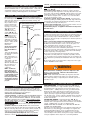
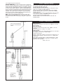
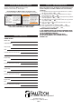
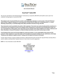
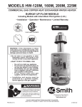
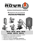
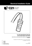
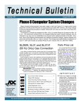
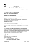
Fall Protection, Precision Engineered.
™
ANCHOR DEVICES
USER'S INSTRUCTION MANUAL
PLEASE NOTE: This manual meets the "Manufacturer's Instructions"
requirements of ANSI A10.14 - 1991 and ANSI Z359.1 - 1992.
It should be read completely and used as part of the User's Training
Program as required by OSHA (1910.66, Appendix C).
WARNING
This is a design-compatible component of a comprehensive Fall
Tech™ Personal Fall Arrest or Fall Restraint System. AS A
USER,YOU MUST READ AND FOLLOW THE MANUFACTURER'S
INSTRUCTIONS, LABELS AND WARNINGS for each component part
of the complete system before using it.
If you do not understand the Instructions, Labels and Warnings for
the use and maintenance of this component, have them explained
to you.
ANY MISUSE OF THIS COMPONENT, ANY ALTERATION OR MODIFICATION OF IT, OR FAILURE TO PROPERLY FOLLOW THESE USER'S
INSTRUCTIONS, MAY RESULT IN SERIOUS INJURY OR DEATH.
ATENCION: TODAS LAS PERSONAS QUE USEN ESTE EQUIPO DEBERAN
LEER Y COMPRENDER O TENER A ALGUIEN QUE LES EXPLIQUE LAS
SIGUENTES INSTRUCCIONES ANTES DE USARLO. EN CASO CONTRARIO SE PODRIAN PRODUCIR LESIONES GRAVES O MORTALES.
ATTENTION: LIRE ET BIEN COMPRENDRE OU SE FAIRE RECITER LES
INSTRUCTIONS AVANT DE SE SERVIR DE CETTE APPAREIL. SINON LA
BLESSURE GRAVE OU LA MORT PEUT ON RESULTE.
ACHTUNG: ALLE BENUTZER DIESES GERATES MUSSEN DIE ANLEITUNGEN VOLLSTANDIG DURCHLESEN UND VERSTEHEN. NICHTBEACHTUNG KANN SCHWERE ODER TODLICHE VERLETZUNGEN ZUR FOLGE
HABEN.
ATTENZIONE: E VERAMENTE MOLTO IMPORTANTE, LEGGERE LE
ISTRUZIONI E CAPIRE COMPLETAMENTE COME SI DEVE ADOPERARE
QUESTO ISTRUMENTO, ALTRIMENTI SI RISCHIA IL PERICOLO DI FARSI
MALE SEVERAMENTE, E PUO RISULTARE ANCHE IN MORTE.
excessive heat, flames or physical deformation.
Don’t use this component if you are working near high voltage power
lines or other energized electrical equipment.
Don’t use this system if you are pregnant, a minor, or have reduced
tolerance to fall forces by reason of age, physical condition or other
pre-existing disorders.
Don’t use near moving machinery which may entangle any component
of the system.
Don’t subject system components to sharp edges or abrasive surfaces.
Don’t use system if your total combined weight (body, clothing, tools,
etc.) exceeds 310 pounds (140 kg).
Don’t use this system if there are any signs of excessive wear,
or any signs of structural deterioration.
Don’t use polypropylene rope with any component of this system.
Don’t knot any components of this system. Knotting reduces
component strength by 50%.
DON’T USE THIS SYSTEM IF IT HAS BEEN USED TO ARREST A FALL. IF
IT HAS BEEN USED TO ARREST A FALL, IT MUST BE REMOVED FROM
SERVICE IMMEDIATELY AND DESTROYED.
FIG. 1A WIRE FORM ANCHOR
Loops Around
Proper Anchor
Point
Squeeze Here To Open
Connect
Lifeline/Lan
yard Here
FIG. 1B FALLTECH™ GRIP ANCHOR
Connect
Lifeline/Lanyard Here
Section 1- Product Description
™
FallTech Wire Form and Grip Anchors (FIG. 1A,1B) are design-compatible components of a comprehensive Personal Fall Arrest, Fall
Restraint, Suspension or Rescue System. They are designed to serve
as anchorage points capable of sustaining a minimum static load of
5,000 pounds (22.2 kN), per attached worker. Once properly installed
(see Section 7), they may be connected to a design-compatible
FallTech Carabiner or Lifeline snap hook.
DO NOT USE ANCHOR DEVICES FOR HANGING, HOISTING OR
SUPPORTING TOOL AND EQUIPMENT.
FIG. 1C CONNECTOR PLATE
Stainless Steel
Anchor Plate
D-ring For
Attaching
Lifeline/
Lanyard
Section 2 - Important Do’s and Don’ts
NOTE: THE COMPONENTS, MATERIALS AND ANCHORAGE OF A
PERSONAL FALL ARREST OR FALL RESTRAINT SYSTEM MUST BE
SELECTED BY A QUALIFIED PERSON TO MATCH THE SYSTEM
APPLICATION, AND WORKPLACE HAZARDS AND ENVIRONMENT.
DO
Do use this component only with other system-compatible components
of a comprehensive personal fall protection or fall restraint system such
as those available from FallTech.
Do use this component only in a system which limits free falls to 6 feet
or less.
Do use extreme caution when rigging this system.
Do rig this system to avoid the hazards of swing falls.
DON’T
Don’t use this component or system to hoist materials.
Don’t use this component if it has been exposed to corrosion, chemicals,
Model 7407 Wire Form Anchor
Model 7408 FallTech Grip Anchor
FIG. 2A (Typical Fall Restraint Setup)
Full Body
Harness
Lanyard
Manual Rope Grab (Roofer's Restraint)
Sheathing Or
Padding To
Protect Lifeline
Against Sharp
Edges
Line
Tensioner
Or Counterweight
(Min.
5 Pounds/
2.3 kg)
5/8"
(16 mm) Lifeline
Lengths: 25 Feet (7.6 m)
and 50 Feet (15 m)
Model 7411 FallTech Connector Plate
Anchor Point
(Must Support
5,000 Pounds
(22.2 kN) Min.,
Per Attached Worker)
Section 3 - ANSI / OSHA Requirements
This FallTech Personal Fall Protection System component fully complies
with ANSI Standards A10.14 - 1991 and ANSI Z359.1 - 1992, and all
current OSHA requirements for fall arrest and fall restraint in general
construction, including 1910.66 Appendix C and 1926.500.
Section 4 - Employer & User Training Responsibilities
OSHA requires that an EMPLOYER shall provide a training program
for each employee who might be exposed to fall hazards. The program
shall teach each employee to recognize the hazards of falling, and
train each employee in
FIG. 2B CLC GRIPLOCK™
the procedures to be folFALL PROTECTION SYSTEM (Typical Setup)
lowed to minimize fall
hazards. Prior to work
requiring a Personal Fall
Arrest System (PFAS)
(FIG. 2A) or Fall
Anchor Point
Restraint/Positioning
System (FIG. 2B), the
USER shall be trained by
Rope Grab
a competent person to
(Decelerator)
properly inspect, use,
store and maintain this
equipment according to
the requirements of ANSI
Z359.1 - 1992, and the Lifeline:
25 Feet
Manufacturer’s
(7.6 m)
Instructions.
or 50 Feet
(15 m)
As part of the training
process, the user of
Lanyard with
these Anchor Devices
Shock Absorber
must:
1) Become familiar with
ALL instructions printed in
this manual;
2) Be trained in the correct use and care of this
Full Body
component;
Harness
3) Be aware of its application limits; and
4) Know and understand
the consequences of
improper use of this
component.
NOTE: You must be
trained in the use of
these Anchor Devices
without being subjected
Line Tensioner Or
to a fall hazard. For best
Counterweight (Min.
results, Personal Fall
5 Pounds/2.3 kg)
Protection System training should be reviewed
or repeated at least one
per year.
(FIG. 2A), only a Manual Rope Grab (which can be locked into a
fixed, non-sliding position on the properly anchored Lifeline) may be
used. 4) Minimizing of swing falls. Anchorage point must be directly
above user (FIG. 3A).
5) Fall path clearance check. The amount of clearance needed is
based on the type and length of the connecting subsystem used, and
the location of the anchorage. (FIG. 3B) Total fall distance is the maximum free fall distance (6 feet/1.8 m) plus the distance the Lanyard
shock absorber elongates (max. 3.5 feet/1.1 m). Total fall distance
may not exceed 9.5 feet (2.9 m).
6) Avoidance of sharp edges and other hazards. You must protect
workers by padding or sheathing unprotected sharp edges while work
is being done. All workplace hazards must be eliminated, controlled,
or considered before any work takes place.
7) Rescue and evacuation plan. You must provide a means of rescue
and evacuation for workers should a fall occur.
8) Immediately dispose of equipment which has been subjected to
fall arrest forces.
Section 6 - Visual Inspection Before Each Use
To make sure that this FallTech Anchor Device will perform properly as
part of a Personal Fall Arrest or Fall Restraint System, it is important
that you visually inspect it BEFORE EACH USE. (This Anchor Device
should also be inspected by a competent person other than yourself at
least twice a year.)
What to look for when visually inspecting Anchor Devices:
1) Look to see that Anchor Device is not cracked, bent or deformed.
2) Make sure that Anchor Device is free of excess dirt, paint, oil or
other contaminants which could affect its operation.
3) If Anchor Device has been subjected to fall arrest (or equivalent)
forces, remove it from service immediately and destroy.
4) Look to see that all Anchor Device labels and warnings are securely fastened and still legible. Missing or illegible labels and warnings
must be replaced by contacting FallTech.
5) Look to see that other FallTech Personal Fall Protection System
components (Full Body Harnesses, Lanyards, Rope Grabs, Lifelines,
etc.) are ready for use by visually inpecting each one according to the
User’s Instructions provided by the manufacturer with each component
part.
6) Record the results of your Anchor Device inspection in the Log provided in Section 11 of this manual.
WARNING
If this Anchor Device is damaged, or has been subjected to fall
arrest (or equivalent) forces, it must be removed from service
immediately and destroyed.
NOTE: Harsh environments and weather, prolonged use and other
extreme working conditions may require you to have this Anchor
Device fully inspected by a competent person other than yourself at
least twice a year.
Section 7 - How To Install Anchor Devices
Section 5 - The Fall Protection Plan
As an employer, you must be aware of the factors which affect the
safety of your workers before, during and after a fall. Having a Fall
Protection Plan ready before work begins is the best way to ensure the
ultimate safety and well-being of your employees.
Your Fall Protection Plan Must Include:
1) Proper anchorage. A PROPERLY SELECTED ANCHORAGE POINT IS
CRITICAL TO THE SUCCESS OF A PERSONAL FALL ARREST SYSTEM
(PFAS). OSHA 1910.66 APPENDIX C REQUIRES THAT AN ANCHORAGE POINT (structural beam or member) MUST SUPPORT A STATIC
LOAD OF 5,000 POUNDS (22.2 kN) — PER PERSON ATTACHED TO
THE ANCHORAGE POINT. The anchorage point must be selected to
reduce fall hazards, and to avoid worker contact with objects in the
fall path (FIG. 3B).
2) Limit free fall to 6 ft. (1.8 m) or less. Users of Personal Fall
Protection Systems must not work above the anchorage point. (FIG.
3B) The connecting subsystem of one worker (Lifeline, Lanyard, etc.)
must not cross or tangle with that of another worker. Connecting
subsystems must never be knotted or tied to each other.
3) Positioning / Fall Restraint Only Plan. When a Rope Grab is
attached to a Lifeline for work positioning/ fall restraint purposes
WIRE FORM ANCHOR: FallTech Wire Form Anchors (FIG. 1A) are
designed for attachment to a support member capable of sustaining
the minimum static load required for a Personal Fall Arrest or Fall
Restraint System — 5,000 pounds (22.2 kN), per attached worker.
Grasp the lower portion of the Anchor (below the large loop) and
squeeze the two sides tightly together to open up the large top loop.
Slip the opened top loop past the support member (pipe or beam),
turn 90° and release. Connect a design-compatible Lifeline snap hook
or self-locking Carabiner to the smaller formed “eye” on the bottom of
the Wire Form Anchor.
FALLTECH GRIP ANCHOR: FallTech Grip Anchors (FIG. 1B) are
designed for attachment to a support beam capable of sustaining the
minimum static load required for a Personal Fall Arrest or Fall Restraint
System – 5,000 pounds (22.2 kN), per attached worker.
BEFORE INSTALLING THE ANCHOR, A 3/4” HOLE MUST BE DRILLED
THROUGH THE SUPPORT BEAM.
Must be used in vertical applications only. Grasp the Anchor with your
thumb in the eye and your fingers on the flanges. Pull together and
insert Grip through pre-drilled 3/4” hole in support beam. Release
thumb and fingers. The Grip MUST FIT SNUGLY. A too-loose fit may
cause the Grip to work itself free causing serious injury or death. Attach
a design-compatible Lifeline snap hook or self-locking Carabiner
to the integral O-ring of the Grip Anchor.
FALLTECH CONNECTOR: The FallTech Connector Plate is designed to
be used in a variety of applications to provide secure anchorage. Plate
must be installed using appropriate fasteners (not supplied). Structure
to which the plate is attached must be capable of supporting applicable loads. Proper fasteners (Grade 5 or better recommended) must be
used to secure plate to anchorage. If plate is welded in position, work
must be done by a certified professional welder per current industry
standards. Care must be taken in installation to ensure the D-ring
swivels freely at all times. Welded installations and installations into
masonry must be proof tested to 3,600 pounds.
NOTE: Always follow the Manufacturer’s Instructions, Labels and
Warnings FOR EACH COMPONENT PART of the FallTech Fall Arrest or
Fall Restraint System when connecting any subsystem component to
another.
Section 8 - Maintenance & Storage
Anchor Devices should be cleaned with a mild soap and water solution and wiped dry with a clean cloth.
DO NOT FORCE-DRY ANCHOR DEVICES.
Check Anchor Devices for excessive amounts of dirt, paint, roofing
mastic, oil, etc. which could affect operation.
Store Anchor Devices in a cool, dry place, free of direct sunlight.
DO NOT STORE ANCHOR DEVICES IN AN AREA WHERE CHEMICAL
VAPORS MAY EXIST.
If Anchor Devices are stored for an extended period of time, be sure to
inspect them thoroughly (see Section 6) before use as part of a
Personal Fall Arrest or Fall Restraint System.
DO NOT ATTEMPT TO REPLACE OR REPAIR ANY PART OF THIS
ANCHOR DEVICE.
Section 9 - Product Specifications
FIG.3A
Wire Form Anchor
Construction: 1/4” Stainless steel rated to min. 5,000 lb. (22.2 kN)
tensile strength
FallTech Grip Anchor
Construction: Galvanized steel rated to min. 5,000 lb. (22.2 kN)
along axis
Hole size needed: 3/4” (19 mm) - 7/8” (22mm)
Connector Plate
Construction: Stainless steel. D-rings-plated forged steel, each rated to
min. 5,000 lb. (22.2 kN) min. break strength
(General Specifications)
Capacity: 310 pounds (140 kg) one person, plus clothing, tools, etc.
Part of a system designed to limit fall arrest force to 1,800 pounds
(8 kN) max.
Fully complies with ANSI A10.14 - 1991 and ANSI Z359.1 - 1992
standards, and all current OSHA requirements, including 1910.66
Appendix C and 1926.500.
Made in the U.S.A.
Anchor Point Should Be Directly
Above User To Avoid Swing Fall
Hazard
FIG.3B
Anchor Point
Should Always
Be Above Work
Position
Total Fall Distance =
Free Fall (Max. 6 Feet/
1.8 m) + Lanyard Shock
Absorber Deceleration
Distance (Max. 3.5 Feet/
1.1 m)
Work Level
Maximum Allowable
Free Fall Before Fall
Arrest System
Activates is 6 Feet
(1.8 m)
To Avoid Injury,
Fall Path
Must Be Clear
Of Obstructions
Total Fall Distance
May Not Exceed
9.5 Feet (2.9 m)
Section 10 - On-Product Labels & Warnings
Section 12 - Important Safety Check List
All labels and warnings (FIG. 4) must be securely
attached to Anchor Devices, and be legible:
FIG. 4 Manufacturer’s Warning Labels for Connector Plate
(To Position Retractable Lifeline To System-Compatible Roof Anchor)
Fall Protection,
Precision Engineered.
™
Alexander Andrew, Inc.,
L. A., CA •1- 800 -719-4619
Complies with OSHA and
ANSI requirements.
D-ring: Plated forged alloy
steel rated at 5,000 pounds
(22.2 kN) min. breaking
strength. Plate: Stainless
steel rated at 5,000 pounds
(22.2 kN) min. breaking
strength. Part of a system
designed to limit fall arrest
forces to 1,800 pounds (8
kN) max. Capacity: 310
pounds (140 kg), one person
plus clothing, tools, etc.
MODEL # 7411
YEAR MFG’D
be mounted to structure capable of supporting a min. of
5,000 pounds (22.2 kN) as
All warnings and instructions determined by a qualified person. All connecting hardware
supplied with this product
must be read and followed. and connections must be
compatible. Use only grade 5
Any failure to do so could
or better hardware. Maximum
result in serious injury or
death. This anchor is part of arresting force = 1,800
a comprehensive fall arrest/ pounds. Maximum work
positioning system. See the rating = 310 pounds.
instruction manual for instal- DO NOT REMOVE LABEL.
lation instructions. Plate must
WARNING
CONNECTOR PLATE
NOTE: If labels and warnings are missing or illegible,
contact FallTech immediately at 1-800 -719 -4619.
Section 11-Inspection Log
Before your employees use any FallTech™ Personal Fall Protection
System component, check YES or NO after each of the following
statements:
1) All equipment has been inspected and maintained in accordance
with the User’s Manual. YES ___ NO ___
2) The equipment has been assembled and installed according to
FallTech instructions. YES ___ NO ___
3) The anchorage point meets minimum load requirements per OSHA
1910.66 Appendix C. YES ___ NO ____
4) The equipment has been inspected and found to be in good work
ing condition. YES ___ NO ___
5) Each user has been trained in the proper and safe use of the
equipment. YES ___ NO ____
6) Each user understands the equipment. YES ___ NO ___
7) Each equipment user is in good health and is not under the
influence of alcohol or drugs. YES ___ NO ___
URGENT WARNING TO EMPLOYERS:
A “NO” CHECKED AFTER ANY OF THE ABOVE STATEMENTS COULD
CAUSE SERIOUS INJURY OR DEATH TO THE USER AND/OR TO OTHERS IN THE IMMEDIATE WORK AREA.
YOU ARE LIABLE FOR ANY SUCH INJURY OR DEATH.
DO NOT USE EQUIPMENT IF ANY STATEMENT HAS BEEN
CHECKED “NO”.
ANCHOR DEVICES
MODEL NO.:
PURCHASE DATE:
Inspected By:
Date:
Problems, Defects Noted (If Any):
Inspected By:
Date:
Problems, Defects Noted (If Any):
Inspected By:
Date:
Problems, Defects Noted (If Any):
Inspected By:
Date:
Problems, Defects Noted (If Any):
Fall Protection, Precision Engineered.
™
Alexander Andrew, Inc.
Los Angeles, CA • 1-800 -719 -4619
9M16