1
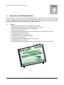
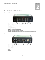
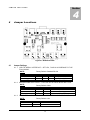
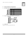
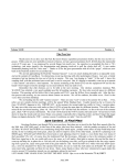
GREEN HERON ENGINEERING LLC RADIO BOSS USB USER GUIDE DOCUMENT REVISION: 1.0 N O V E M B E R 6, 2 01 0 GREEN HERON ENGINEERING LLC Green Heron Engineering LLC 1107 Salt Road Webster, NY 14580 Phone 585.217.9093 Email: [email protected] RADIO AND TELEVISION INTERFERENCE This equipment has been tested and found to comply with the limits for a Class B digital device, pursuant to Part 15 of the FCC rules. These limits are designed to provide reasonable protection against harmful interference in a residential installation. This equipment generates uses and can radiate radio frequency energy and, if not installed and used in accordance with the instructions, may cause harmful interference to radio communications. However, there is no guarantee that interference will not occur in a particular installation. If this equipment does cause harmful interference to radio or television reception, which can be determined by turning the equipment off and on, the user is encouraged to try to correct the interference by one or more of the following measures: Reorient or relocate the receiving antenna. Increase the separation between the equipment and the receiver. Connect the equipment into an outlet on a circuit different from that to which the receiver is connected. Consult the dealer or an experienced radio/TV technician for help. You may also find helpful the following booklet, prepared by the FCC: "How to Identify and Resolve Radio-TV Interference Problems." This booklet is available from the U.S. Government Printing Office, Washington D.C. 20402. Changes and Modifications not expressly approved by the manufacturer or registrant of this equipment can void your authority to operate this equipment under Federal Communications Commissions rules. NOTICE Green Heron Engineering reserves the right to make changes for product improvement or manufacturing, without notice or any obligation to update units already sold. WARRANTY This product is warranted to be free of defects in materials and workmanship for 1 year. We will repair or replace, at our option, any equipment proven to be defective within the warranty period. All warranty work is F.O.B. Webster, NY, USA. This warranty is exclusive of abuse, misuse, accidental damage, acts of God or consequential damages, etc. Green Heron Engineering LLC liability shall not exceed the original purchase price of the equipment. TRADEMARKS Kenwood is a trademark of Kenwood Corporation Icom is a trademark of Icom Inc. All other products, company names, brand names, and trademarks are the property of their respective owners. Table of Contents 1 Overview and Description ...................................................................... 1 2 Controls and Indicators .......................................................................... 2 3 Installation ............................................................................................. 3 4 Jumper Locations .................................................................................. 4 5 Serial Interface Assignments .................................................................5 Appendix A: Helpful Links ............................................................................... 6 Appendix B: Additional Information .................................................................7 O V E R V I E W 1 A N D D E S C R I P T I O N Section 1 Over view and Description Radio Boss USB is a universal radio interface designed specifically to meet the needs of the multi-mode contest operator. It provides all the commonly needed computer interface requirements for your radio in one compact package. The Radio Boss USB is fully isolated and is compatible with all radio MIC, Data and Accessory ports. Radio Boss USB solves many of the problems associated with available interfaces: 1.1 Features High performance USB to RS-232, TTL/CMOS and CI-V adaptor Works with any serial device using RS-232, TTL/CMOS or CI-V interfaces Works with virtually all Amateur Radio software applications Supports all voice and data modes Three optically isolated keying outputs using the standard RS232 signals DTR, RTS and TXD LED indicators for TXD, RTS and DTR Compatible with MMTTY EXT-FSK mode Compatible with XP, Vista, Windows 7 and MAC Front Panel Audio Level Controls Completely USB Powered (No other external power required) Uses Standard Connectors and Cables Unique “Same COM Port” USB assignment allows multiple Radio Boss devices on the same PC 1 C O N T R O L S A N D I N D I C A T O R S 2 Controls and Indicator s 2.1 Front Panel 1. 2. 3. 4. 5. 6. 7. 8. 2.2 Section 2 TX Level – Adjusts the level of the audio going to the Radio from the Computer Sound Card EXT IN – Audio IN from Computer Sound Card MIC – Optional MIC input AUDIO OUT – Audio output to Radio for TX LED's (DTR, RST, TXD) AUDIO IN – Audio input from Radio for RX EXT OUT – Audio OUT to Computer Sound Card RX Level – Adjusts the level of the audio going to the Computer Sound Card from the radio. Rear Panel 1. 2. 3. 4. 5. 6. TXD Output (Optical Isolated) RTS Output (Optical Isolated) DTR Output (Optical Isolated) RS-232 (TTL) DB-9 USB Icom CI-V 2 I N S T A L L A T I O N 3 Installation 3.1 Connecting to the Computer Section 3 1. Connect supplied USB cable to any available USB port. Most computers will recognize and install the correct driver directly from within Windows. 2. If prompted, follow the “New Hardware Found” wizard; Allow “Search Windows Update for Drivers”. Follow Wizard prompts as required. 3. Confirm USB COM Port with “Device Manager”. This will always be the COM port used on this computer for this specific Radio Boss Unit. Radio Boss USB shows up in device manager as a “USB Serial Port (COMx)”. 4. If you have additional Radio Boss Units they will be automatically installed upon plug-in. NOTE: If the COM port the Radio Boss installs on a port that is out of the range of COM ports allowed by your specific application, please refer to the Operation Notes at the end of this manual. 3.2 3.3 Configuration and Connections to Serial Devices (Radio, or other RS-232) 3.2.1 RS-232 SERIAL DEVICES -- Set Jumpers 6, 7 & 8 as follows: JP6 JP7 JP8 2-3 2-3 1-2 3.2.2 KENWOOD TTL RADIOS -- Set Jumpers 6, 7 & 8 as follows: JP6 JP7 JP8 1-2 2-3 2-3 3.2.3 ICOM CI-V -- Set Jumpers 6, 7 & 8 as follows: JP6 JP7 JP8 1-2 1-2 1-2 3.2.4 SERIAL DEVICES 1. A l l S er ia l D e v ic es are c on n ec t e d us in g t he D B - 9 ( R S- 2 3 2 / T T L) or th e ICO M j ac k ( C I - V) : Configuration and Connections to Microphone and external Audio 1. Referring to the Jumper Settings table(s), select the jumper setting (JP6) for MIC switching. (Factory default = NONE) 2. Connect an external computer microphone to “MIC” as required. 3. Referring to the Jumper Settings table(s), select the jumper setting (JP4) for the audio output from the computer to the Radio Boss. 4. Connect Computer Audio Out from Line Out or Speaker Out to “EXT IN” 5. Connect radio microphone or radio external audio input to “AUDIO OUT” 6. Connect radio audio out to “AUDIO IN” 3.4 Connect Keying Jacks as Needed 1. DTR is usually used for CW or FSK 2. RTS is usually used for PTT 3. TXD is an optional selection in software for CW or FSK 3 J U M P E R 4 L O C A T I O N S Section 4 Jumper Locations Figure 4-1: Radio Boss PCB 4.1 Jumper Settings 4.1.1 USB TO SERIAL INTERFACE – SET JP6, 7 AND 8 ACCORDING TO THE FOLLOWING: NOTE: Factory Default = Standard RS-232 TYPE Standard RS-232 Icom CI-V Kenwood TTL 4.1.2 JP6 2-3 1-2 1-2 JP8 1-2 1-2 2-3 COMMENTS DB-9 One Radio via CI-V DB-9 RX=2, TX=3 MICROPHONE SWITCHING – FOR USE WITH RADIO BOSS MIC JACK NOTE: Factory Default = None Switch to MIC on: None DTR RTS 4.1.3 JP7 2-3 1-2 2-3 JP1 IN OUT OUT JP2 OUT 2-3 1-2 Comments MIC into Computer or Radio Switches to MIC on DTR Switches to MIC on RTS COMPUTER AUDIO OUT – EXTRA ATTENUATION FOR SPKR OUT NOTE: AUDIO OUT Line Speaker Factory Default = Line JP4 OUT IN Comments Extra Attenuation OUT Extra Attenuation IN 4 S E R I A L I N T E R F A C E A S S I G N M E N T S Section 5 5 Serial Interface Assignments 5.1 RS 232 DB9 Assignment When Unit is Jumpered for Standard RS-232 Pin # 1 2 3 4 5 6 7 8 9 Name DCD RXD TXD DTR SGND DSR RTS CTS RI Description Data Carrier Detect Receive Data (a.k.a. RD, Rx) Transmit Data (a.k.a. TD, Tx) Data Terminal Ready Ground Data Set Ready Request To Send Clear To Send Ring Indicator 5.2 Kenwood TTL DB9 Connection When Unit is Jumpered for TTL 5.3 ICOM CI-V-232 Standard Icom CI-V cable, ensure Jumpers are set for CI-V first. 5 A P P E N D I X A Appendix A: Helpful Links General: Sound Card Problems -- Windows Vista http://windows.microsoft.com/en-US/windows-vista/Tips-for-fixing-common-sound-problems QuickMix (Save & Restore Sound Card Settings) http://www.ptpart.co.uk/quickmix/ Sound Card Tester (executable from westmountainradio.com) http://www.westmountainradio.com/exe/SoundCardTest.exe Logging, Rig control and CAT Software: Ham Radio Deluxe http://www.ham-radio.ch/ WriteLog TRX Manager WinEQF VHFlog TR Log N1MM Logger http://www.writelog.com/ http://www.trxmanager.com/ http://www.win-eqf.com/ http://www.qsl.net/w3km/features.htm http://www.trlog.com/ http://www.n1mm.com/ RTTY Software MMTTY EXTFSK plug-in for MMTTY HamScope http://mmhamsoft.amateur-radio.ca/pages/mmtty.php http://mmhamsoft.amateur-radio.ca/pages/mmtty/ext-fsk.php http://www.qsl.net/hamscope/ 6 A P P E N D I X B Appendix B: Additional Infor mation What do I do if my application won’t support a COM # this high? The assigned Radio Boss comport in your computer may be too high for proper utilization by your logging or contest software. Usually this is a result of running software that creates virtual communications ports each time it was installed or executed. In normal operation, Windows XP does not display these ports and they are hidden from view, which makes it impossible to delete. To delete unwanted and hidden COM ports: 1. Click Start >All Programs > Accessories and then click Command Prompt. 2. Type set devmgr_show_nonpresent_devices=1 in the Command Prompt window and then press Enter. 3. Type cd \Windows \system32 in the Command Prompt window and then press Enter. 4. Type start devmgmt.msc in the Command Prompt window and then press Enter. 5. Click View >Show hidden devices. This will display devices that are not connected to your computer and you can delete what you do not need Windows 7 USB devices that are connected to a computer may not work after the computer is idle for more than one hour Windows 7. Please refer to this Microsoft Support Article. http://support.microsoft.com/kb/978258 MMTTY-EXTFSK Driver EXTFSK.DLL is an additional driver that is used with MMTTY to allow software control of FSK and PTT keying for devices like Radio Boss USB that do not support direct 5 bit Baudot. .On RS-232 ports (and some USB adapters) these functions have traditionally been controlled by the hardware UART. With EXTFSK, you can key PTT and FSK using DTR and RTS on the Radio Boss USB port. Using another third party product, it is even possible to do Rig Control on the same port, all using one Radio Boss USB. http://www.eterlogic.com/Products.VSPE.html. (See Appendix C for specific example) EXTFSK is available from MMTTY page of the MM Hamsoft web site. EXTFSK is contained in the comfsk105.zip file along with the source code and readme.txt file. To use EXTFSK, download comfsk105.zip, unzip it and place EXTFSK.DLL in the same directory as MMTTY.EXE. The readme.txt file contains the information needed to use EXTFSK.DLL. 7