1
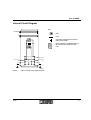
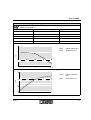
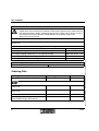
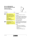
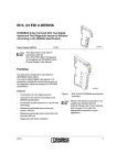
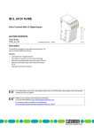
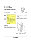
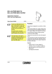
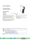
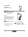
IB IL 24 SEG/F
INTERBUS Inline
Segment Terminal With Fuse
Data Sheet 5656B
5 6 5 6 A 0 0 1
02/2001
This data sheet is intended to be used
in conjunction with the “Configuring
and Installing the INTERBUS Inline
Product Range” User Manual
IB IL SYS PRO UM E.
Function
The segment terminal is designed for use within
an INTERBUS Inline station. It is used to create
a fused partial circuit (segment circuit) within the
main circuit. The terminal is not used to supply
power and has no components for protection
against polarity reversal and surge voltage.
Features
5 6 5 6 A 0 0 5
This terminal does not have an
INTERBUS protocol chip and is not a
bus device.
–
Automatic creation of a segment circuit
within the main circuit
–
Segment circuit protected by internal fuse
–
Diagnostic indicators
5656B
Bild 1
IB IL 24 SEG/F terminal
with the connector plugged in
Please note that the connector is not
supplied with the terminal. Refer to the
ordering data on page 8 to choose the
appropriate connector for your application.
1
IB IL 24 SEG/F
Local Diagnostic Indicators
Des.
U S
Color Meaning
E
US
S E G /F
E
Green 24 V voltage
(in segment circuit US); prior to
fuse
Red
Fuse in the segment terminal
(in segment circuit US)
A blown fuse is indicated by diagnostic indicator E (LED E is on).
Terminal Assignment
1
The terminal points are provided for
measuring purposes only! Power is
injected using a bus terminal or a
power terminal.
2
1 .1
1
1
2 .1
1 .2
2
2
2 .2
1 .3
3
3
2 .3
1 .4
4
4
Terminal Assignment
point
2 .4
5 6 5 6 A 0 0 2
Bild 2
IB IL 24 SEG/F with the appropriate
connector
Function Identification
1.1, 2.1
Segment voltage US
(after the fuse)
1.2, 2.2
Main voltage UM
1.3, 2.3
GND of the supply voltages
1.4, 2.4
FE connection
Black
2
5656B
IB IL 24 SEG/F
Internal Circuit Diagram
Key:
IN T E R B U S
LED
U L
Fuse
Capacitive coupling to functional
earth ground (FE)
Other symbols are explained in the
IB IL SYS PRO UM E User Manual.
+ 2 4 V (U S )
+ 2 4 V (U M )
+ 2 4 V (U M )
5 6 5 6 B 0 0 3
Bild 3
5656B
Internal wiring of the terminal points
3
IB IL 24 SEG/F
Technical Data
General Data
Housing dimensions (width x height x depth)
12.2 mm x 120 mm x 71.5 mm
(0.480 in. x 4.724 in. x 2.795 in.)
Weight
44 g (without connector)
Permissible temperature (operation)
-25°C to +55°C (-13°F to +131°F)
Permissible temperature (storage/transport)
-25°C to +85°C (-13°F to +185°F)
Permissible humidity (operation)
75% on average, 85% occasionally
Ranging from -25°C (-13°F) to +55°C (131°F) appropriate measures against increased
humidity (> 85%) must be taken.
Permissible humidity (storage/transport)
75% on average, 85% occasionally
For a short period, slight condensation may appear on the housing if, for example, the
terminal is brought into a closed room from a vehicle.
Air pressure (operation)
80 kPa to 106 kPa
(up to 2000 m [6562 ft.] above sea level)
Air pressure (storage/transport)
70 kPa to 106 kPa
(up to 3000 m [9843 ft.] above sea level)
Degree of protection
IP 20 according to IEC 60529
Class of protection
Class 3 according to VDE 0106, IEC 60536
24 V I/O Supply
Voltage is supplied through the bus terminal or power terminal.
No connections for supply voltage are required on the segment terminal. The corresponding terminals are available for testing purposes only.
Permissible Total Current in the Voltage Jumpers of the Main and Segment Circuits
Nominal current of the terminal
6.0 A
Maximum permissible value
8.0 A
The terminal is delivered with a 6.3 A slow-blow fuse. If there is a higher total current in
the voltage jumpers UM and US, the user must ensure a better protection of the current
circuit through appropriate fuses. Please note the information for the selection of fuses
given on page 7.
4
5656B
IB IL 24 SEG/F
Characteristic of the Voltage in the Segment Circuit When the Fuse Is Blown
Note that power is not disconnected even after the fuse has blown! Observe the characteristic curves below!
Load Resistance (Ω)
Typical Output Voltage (V)
Typical Current (mA)
1000000
12.80
0.013
100000
12.21
0.122
10000
8.60
0.86
1000
1.99
1.99
100
0.28
2.8
Typical output voltage in relation to resistance within the segment circuit
1 0 0
U [V]
Output voltage in V
R [Ω]
Resistance in Ω
U
[V ]
1 0
1
1 0 0 0 0 0 0
1 0 0 0 0 0
1 0 0 0 0
1 0 0 0
1 0 0
0 .1
R [W ]
5 6 5 6 A 0 0 9
Typical output current in relation to resistance within the segment circuit
1 0
1
1 0 0 0 0 0
1 0 0 0 0
1 0 0 0
1 0 0
Output current in
mA
R [Ω]
Resistance in Ω
I [m A ]
1 0 0 0 0 0 0
I [mA]
0 ,1
0 .0 1
5656B
R [W ]
5 6 5 6 A 0 1 0
5
IB IL 24 SEG/F
Power Dissipation
Formula to calculate the power dissipation of the electronics
P
= 0 .1 8 0 W
to t
With
Ptot
IS
RF
+ IS 2 x R
F
Total power dissipation of the terminal
Load current in the segment circuit
Resistance of the fuse
The resistance of fuse RF for a 6.3 AT fuse is approx. 50 mΩ.
Power dissipation of the housing depending on the ambient temperature
P
P
H O U
= 2 .4 W
H O U
= 2 .4 W
With
PHOU
TU
-2 5 °C < T
-
T
U
- (-5 °C )
-5 °C < T
3 7 .5 K /W
U
U
£ -5 °C
£ + 5 5 °C
Permissible power dissipation of the housing, maximum
Ambient temperature
Typical power dissipation of the electronics in relation to the load current in the segment
circuit
P [mW] Power dissipation in mW
IS [A]
3 5 0 0
3 0 0 0
P [m W ]
2 5 0 0
Load current in the segment circuit in A
This test was carried out with a
10 AT fuse.
2 0 0 0
1 5 0 0
1 0 0 0
5 0 0
0
0 .1
0 .5
1
2
IS [A ]
6
4
6
8
5 6 5 6 A 0 0 7
5656B
IB IL 24 SEG/F
Derating of the Load Current in the Segment Circuit
Ambient temperature TU in °C
Load current in the segment circuit IS in A
55°C (131°F)
4.0 A
45°C (113°F)
6.3 A
Permissible load current in the segment circuit in relation to the ambient temperature
8
7
6
IS [A ]
5
4
3
2
1
0
-2 5
-2 0
-1 5
-1 0
-5
0
5
1 0
1 5
T
IS [A]
TU [°C]
U
2 0
2 5
3 0
3 5
4 0
4 5
5 0
5 5
5 6 5 6 A 0 0 6
[° C ]
Load current in the segment circuit in A
Ambient temperature in °C
Safety Devices
Overload/short circuit in segment circuit
Fuse 5 x 20 (6.3 A slow-blow)
You may also use fuses with other values. The maximum fuse value is 8 A.
Note for the selection of fuses:
Only use slow-blow fuses for currents higher than 2 A!
Surge voltage
Protective elements in the power terminal or the
bus terminal
Protection against polarity reversal
Protective elements in the power terminal or the
bus terminal
5656B
7
IB IL 24 SEG/F
Electrical Isolation
To provide electrical isolation between the logic level and the I/O area, it is necessary to
supply these areas from the bus terminal or from the bus terminal and a power terminal
with separate power supplies. Interconnection of power supply units in the 24 V range is
not allowed. Please pay attention to GND-PE links at the power supply units!
(Refer also to user manual)
Common potentials
24 V main power, 24 V segment voltage, and GND have the same potential. FE is a separate potential area.
Separate system potentials consisting of bus terminal/power terminal and I/O terminal
- Test voltage
5 V supply incoming remote bus / 7.5 V supply (bus logic)
500 V AC, 50 Hz, 1 min
5 V supply outgoing remote bus / 7.5 V supply (bus logic)
500 V AC, 50 Hz, 1 min
7.5 V supply (bus logic) / 24 V supply (I/O)
500 V AC, 50 Hz, 1 min
24 V supply (I/O) / functional earth ground
500 V AC, 50 Hz, 1 min
Technical modifications reserved TNR 94 23 78 5
- Test distance
Error Messages to the Higher-Level Control or Computer System
None
Ordering Data
Meaning
Order Designation
Order No.
Segment terminal with fuse
IB IL 24 SEG/F
27 27 74 7
Connector (black, w/o color print)
pack of 10
IB IL SCN-PWR-IN
27 27 46 2
Connector (black, with color print)
pack of 10
IB IL SCN-PWR-IN-CP
27 27 63 7
Fuse
SI 5 x20 6,300 A T
50 30 51 2
“Configuring and Installing the INTERBUS
Inline Product Range” User Manual
IB IL SYS PRO UM E
27 43 04 8
8
© Phoenix Contact 02/2001
A connector is needed for the power supply of the terminal
5656B