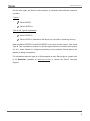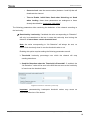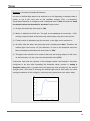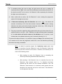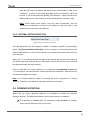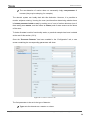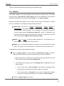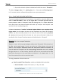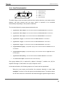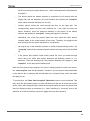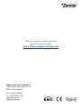
1
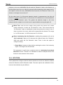
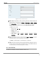
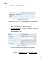
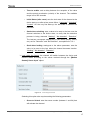
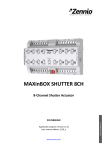
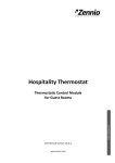
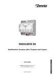
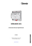
Motion Detector Motion Detector with Luminosity Sensor USER MANUAL ZN1IO-DETEC / ZN1IO-DETEC-N / ZN1IO-DETEC-P / ZN1IO-DETEC-X User Manual Version: [0.2]_b www.zennio.com Motion Detector Contents Document updates ........................................................................................................................ 3 1 2 3 Introduction .......................................................................................................................... 4 1.1 Zennio Motion Detector................................................................................................ 4 1.2 Models and Supported Devices .................................................................................... 4 Installation............................................................................................................................. 6 2.1 General Installation ....................................................................................................... 6 2.2 Connecting the detector to the device ......................................................................... 8 2.3 Connecting multiple parallel detectors ......................................................................... 8 ETS Parameterisation .......................................................................................................... 10 3.1 Input ............................................................................................................................ 10 3.2 Channels ...................................................................................................................... 12 3.2.1 Detection ............................................................................................................ 14 3.2.2 No Detection ....................................................................................................... 15 3.2.3 Channel Lock and Restrictions ............................................................................ 16 3.2.4 Forced States ...................................................................................................... 22 3.2.5 External Motion Detection ................................................................................. 23 3.3 Presence Detection ..................................................................................................... 23 3.3.1 Master................................................................................................................. 25 3.3.2 Slave .................................................................................................................... 27 3.3.3 Practical Example ................................................................................................ 28 List of examples Detection States .......................................................................................................................... 12 Length of the Detection ............................................................................................................. 13 Luminosity-Constrained Detection ............................................................................................. 19 Luminosity Reset ......................................................................................................................... 20 Luminosity Reset (delayed) ......................................................................................................... 20 Presence Detection ..................................................................................................................... 28 http://www.zennio.com Technical Support: http://zennioenglish.zendesk.com 2 Motion Detector DOCUMENT UPDATES Version Changes Page(s) Added minor details about the Forced States function. 23 Added minor details about the Presence Detection function. 24 [0.2]_b http://www.zennio.com Technical Support: http://zennioenglish.zendesk.com 3 Motion Detector 1 INTRODUCTION 1.1 ZENNIO MOTION DETECTOR The Zennio Motion Detector is an optional accessory that, connected to any Zennio device equipped with inputs, permits detecting motion (e.g., moving subjects) in the environment of the room where it is installed, by means of the built-in infrared technology. In addition to the binary motion detection (yes / no), a function for measuring the luminosity has been incorporated, which makes it a very versatile accessory. Finally, it brings the option to notify the KNX bus about errors in the connection or in the detector itself, through the Short-Circuit / Open Circuit functions. Figure 1. Zennio Motion Detector 1.2 MODELS AND SUPPORTED DEVICES The Zennio Motion Detector is marketed as an optional accessory for the variety of Zennio devices equipped with inputs and whose application program is specifically compatible with the Zennio motion detector. The user manuals of the Zennio devices specifically make reference to this functionality, so please refer to them to confirm whether a particular device is compatible with the motion detector or not. Moreover, the behaviour and the options of the motion detection function may differ slightly depending on the Zennio device it is connected to. Therefore, the user manual of the motion detector has been particularised for each device. To access the documentation, it is highly recommended to make use of the links provided at the Zennio homepage (www.zennio.com) within the specific section of the particular device being configured. http://www.zennio.com Technical Support: http://zennioenglish.zendesk.com 4 Motion Detector On the other hand, the Zennio motion detector is marketed under different reference numbers: Type A: ZN1IO-DETEC, ZN1IO-DETEC-N. Type A and Type B (switchable): ZN1IO-DETEC-P. ZN1IO-DETEC-X (identical to the above one, but with no luminosity sensor). Note that ZN1IO-DETEC-P and ZN1IO-DETEC-X can work in both modes, Type A and Type B. This is possible by means of a specific type selection micro-switch (see section 2.2 2.1), which should be configured according to the particular Zennio device the detector is being connected to. For information about the type (A or B) that applies to each Zennio device, please refer to its Datasheet (available at www.zennio.com) or contact the Zennio Technical Support. http://www.zennio.com Technical Support: http://zennioenglish.zendesk.com 5 Motion Detector 2 INSTALLATION 2.1 GENERAL INSTALLATION The Zennio Motion Detector needs to be connected to any of the available input ports of the Zennio device (please refer to the specific user manual of the target device for further details). Once connected to the device, the detector needs no further electrical power; it will be ready to function once the Zennio device gets programmed. C A A. LED Indicator. B. Detection Cell. C. Connection Terminal. B D. Double Microswitch. E. Metal Clamp. E D Figure 2. Element Diagram (models ZN1IO-DETEC and ZN1IO-DETEC-N) C A A. LED Indicator. B. Detection Cell. B C. Connection Terminal. D. Triple Microswitch. E. Metal Clamp. E D Figure 3. Element Diagram (models ZN1IO-DETEC-P and ZN1IO-DETEC-X) Figure 2 and Figure 3 show the main elements of the device: LED Indicator (A): LED light that will blink in red colour when motion is detected. The luminosity levels are obtained from the light that strikes this hole. Detection Cell (B): cell for the motion detection. http://www.zennio.com Technical Support: http://zennioenglish.zendesk.com 6 Motion Detector Connection Terminal (C): slot for inserting the device connecting cables. Double/Triple Micro-switch (D): Models ZN1IO-DETEC and ZN1IO-DETECT-N These two switches enable or disable the luminosity measurement (switch #1) and the blinking of the LED on the detection of motion (switch #2). LUM On LUM Off LUM On LUM Off LED On LED Off LED Off LED On Figure 4. Positions of the Double Micro-Switch Models ZN1IO-DETEC-P and ZN1IO-DETEC-X These switches allow enabling or disabling the luminosity measurement (switch #1; only functional in model ZN1IO-DETEC-P) and the blinking of the LED on the detection of motion (switch #3). Switch #2, on the other hand, allows selecting the Type A or Type B working modes, depending on the Zennio device the detector is being connected to. LUM On LUM Off LUM On LUM Off Type A Type A Type A Type A LED On LED Off LED Off LED On LUM On LUM Off LUM On LUM Off Type B Type B Type B Type B LED On LED Off LED Off LED On Figure 5. Positions of the Triple Micro-Switch Important: please refer to section 1.2 for information about the differences between all the models and their compatibility with the different Zennio devices. Metal Clamps (E): spring clamps that help secure the detector after the installation. http://www.zennio.com Technical Support: http://zennioenglish.zendesk.com 7 Motion Detector It is possible to accommodate the motion detector in the false ceiling of the room by drilling a 40-mm diameter corona and inserting the detector (previously connected to the device) with its metal clamps folded (see section 2.2). For installation tips and suggestions, it is also important to review the “Installation” technical note, available at the Zennio homepage (www.zennio.com). 2.2 CONNECTING THE DETECTOR TO THE DEVICE Figure 6. Connection to the Device During the connection of the detector to the device, the terminal labeled as “I” on the detector side needs to meet the desired input slot (1, 2, etc.) on the side of the target device, while the terminal labeled as “C” on the detector plug should be connected to the common input slot (identified as well as “C”) in the target device. 2.3 CONNECTING MULTIPLE PARALLEL DETECTORS It is possible to connect multiple parallel detectors (typically two, but may be more depending on the model) to the same input port of the device, so that a wider detection area is covered, while both detectors still work (and are configured) as if they were only one detector, which does not apply when two input ports are used. Important: please refer to the datasheet of the motion detector for the maximum number of them that can be connected in parallel to the same input. Figure 7 illustrates this type of assembly, with one of the two wires of each detector (the one labeled as “I”) connected to a particular input of the device and the remaining two wires (labeled as “C”) connected to the common input port. http://www.zennio.com Technical Support: http://zennioenglish.zendesk.com 8 Motion Detector However, under this set-up it is mandatory that the luminosity measuring function is not active in more than one detector (see section 2.1). Otherwise the measurements sent by the detectors may interfere each other. Figure 7. Connecting Two Parallel Detectors Note: Zennio devices compatible with the motion detector typically provide the option to enable multiple virtual detection channels, which makes it possible to simultaneously implement a variety of reactions and behaviours, although all of them associated to a sole input value. The number of the available virtual channels is not related at all with how many detectors are connected. Moreover, from the hardware point of view, multiple detectors connected to the same input are considered as only one detector. For detailed information about the technical features of the motion detector, as well as on security and installation procedures, please refer to the device Datasheet, bundled within the device packaging and also available at www.zennio.com For installation tips and suggestions, it is also important to review the “Installation” technical note, available at the same address. Important: the next sections of this manual refer to different functions related to the measurement of the luminosity. Please ignore all them for model ZN1IO-DETEC-X. http://www.zennio.com Technical Support: http://zennioenglish.zendesk.com 9 Motion Detector 3 ETS PARAMETERISATION 3.1 INPUT Once the corresponding input of the device has been configured to work as a motion detector (please refer to the user manual of the device itself for further details), the “Configuration” tab shows up. Figure 8 illustrates this. Moreover, a set of communication objects are available by default: [Ix] Short Circuit Error: 1-bit object that will notify the KNX bus (by sending a “1” every 30 seconds) about short-circuit events in the detector wiring or in the detector itself. Once solved, the value “0” will be sent (once) through the same object. [Ix] Open Circuit Error: 1-bit object that will notify the KNX bus (by sending the value “1” every 30 seconds) about open-circuit events in the detector wiring or in the detector itself. Once solved, the value “0” will be sent (once) through the same object. [Motion Sensor] Scene Input: 1-byte object through which it will be possible to receive scene values (0 – 63, both included) from the bus. [Motion Sensor] Scene Input: 1-byte object through which it will be possible to send scene values (0 – 63, both included) to the bus. Note: object names may differ slightly depending on the input port where the motion detector has been connected. Figure 8. ”Configuration” Tab The following parameters are available in the Configuration tab: http://www.zennio.com Technical Support: http://zennioenglish.zendesk.com 10 Motion Detector Number of sensors connected to the input: sets the number of sensors (one or two) connected to the same input, in order to adequately calibrate the luminosity and detection readings. Please see section 2.3 for more details. Luminosity Sending: activates or deactivates the option to periodically send the luminosity level to the KNX bus (in terms of percentage, through object “[Ix] Luminosity”). If checked, the following parameters show up: Period: period for sending the luminosity level to the bus, between 0 and 255 seconds. If set to 0, the periodical sending remains disabled. Luminosity change to send: sets a certain increment (in percentage) so that when two consecutive readings of the luminosity are found to differ by more than such value, an extra sending of the luminosity to the bus will take place. If set to “0”, this type of transmission is disabled. Figure 9. Luminosity Sending As stated, the luminosity level is sent through the “[Ix] Luminosity” 1-byte object. The higher the light level detected in the room is, the greater the value of this object will be. Note: bear in mind that during continuous motion detection, the value of the luminosity level may take a little more time to update, as both signals (detection and luminosity) share the same input port of the device. motion motion Figure 10. Luminosity Readings during Motion Detection Events. http://www.zennio.com Technical Support: http://zennioenglish.zendesk.com 11 Motion Detector Channels 1-X: activates or deactivates the different virtual detection channels. Every channel will work independently, which makes it possible to set different parameters (delays, thresholds, etc.) and different parallel reactions to the readings sent by a sole physical detector. Presence Detector: activates or deactivates the presence detection function. 3.2 CHANNELS When a channel is enabled, ETS displays a new tab (“Channel i”), which is divided into several parts. Figure 11. Channel Configuration Basically, the channel will switch to the “Detection” state when a motion detection signal is received from the sensor and to the “No Detection” state when such signal is no longer received. It will be possible to define a Detection Length and a Blind Time to ensure the channel remains in the new state for at least a certain time, after which it will listen again to the signal received from the sensor. The following example illustrates this. Example: Detection States. The graph below shows the following succession of events: At t1, the sensor activates the motion signal. The channel switches then to the “Detection” state and sends a “1” through “[Ix][Ci] Detection State”, making for example a lamp turn on. http://www.zennio.com Technical Support: http://zennioenglish.zendesk.com 12 Motion Detector At t2, motion is no longer detected; however the channel remains in “Detection” and starts counting the parameterised Detection Length time (T1). At t3, the channel switches to “No Detection” and sends a “0” (making the lamp turn off). After that, it starts counting the parameterised Blind Time (T2). Although at t4 the sensor starts reporting motion again, the channel does not switch to “Detection” until T2 ends, that is, until t5. At t6 the sensor stops reporting motion, so the channel starts a new Detection Length count. At t7, before T1 concludes, motion is reported again, so the count for the Detection Length is interrupted, remaining the channel in “Detection” without having switched to “No Detection” between t6 and t7. t1 t2 t3 t4 t5 t6 t7 Figure 12. Channel Detection States vs. Motion Signal The upper parameters of this tab basically define the aforementioned delays: Length of Detection: sets the minimum time that should elapse without any motion before the channel switches to the “No Detection” state. Further motion events will interrupt this countdown. The range is 1 to 255 seconds, 1 to 255 minutes and 1 to 18 hours. Example: Length of the Detection. One MAXinBOX 66 and one motion detector are being used to turn on/off a light source (which is connected to a KNX light dimmer) depending on whether motion is being detected or not in the room. If the detection length is set to 5 seconds, as soon as the detector finds moving http://www.zennio.com Technical Support: http://zennioenglish.zendesk.com 13 Motion Detector subjects in the room, MAXinBOX 66 will send the “Detection” value to the dimmer, so that the light source turns on. After five seconds without detecting motion again (even if the subject is still in the room), MAXinBOX 66 will send the “No Detection” value to the dimmer, so the light source turns off. On the other hand, if a 60-second detection length is parameterised, the light will remain on at least for 60 seconds, as 60 seconds of no detection are necessary before sending the “No Detection” value. The greater the detection length is, the more evidence that the subject is not in the room is required before turning the lights off. Blind Time: sets the time margin during which the channel will remain inactive whenever it enters the “No Detection” value. This ensures that the “No Detection” state is maintained at least during that time interval, even if there is motion in the room, which will be ignored by the channel. The range is 1 to 255 seconds, 1 to 255 minutes and 1 to 18 hours. Reset Luminosity after No Detection: enabling this parameter will set the “[Ix] Luminosity” object to 0% whenever the channel leaves the “Detection” state and enters the “No Detection” state. There is also the option to configure a delay. Reset Delay: imposes a delay before resetting the value of the luminosity object. The range is 0 to 60 seconds. This parameter is useful when combined with the Luminosity-Constrained Detection function. Therefore it is advisable to read the examples about such function in later sections of this manual. 3.2.1 DETECTION These parameters configure what the device should send to the bus when the channel enters the Detection and No Detection states. The same options are available for both; however their defaults may be different. http://www.zennio.com Technical Support: http://zennioenglish.zendesk.com 14 Motion Detector Figure 13: Channel – detection function Send Type: sets what to send to the bus when the channel enters the Detection state. The options are “Nothing”, “Binary Value”, “Scene”, “Scaling” and “HVAC Mode”. Scenes will be sent through “[Motion Sensor] Scene Output”, while the other will be sent through “[Ix][Ci] Detection State”. Value: value to send. • Binary Value: “Off”, “On”. • Scene: 1 to 64. • Scaling: 0% to 100%. • HVAC Mode: “Auto”, “Comfort”, “Standby”, “Economy”, “Building Protection”. Mode: sets whether the above value will be sent once or cyclically. In case of selecting the latter, one more parameter will show up: Period: 1 to 255 seconds, 1 to 255 minutes, 1 to 18 hours. Delay: sets the time that the device should wait before sending the value to the bus, after the channel enters the Detection state. The available values are 0 to 255 seconds, 0 to 255 minutes and 0 to 18 hours. 3.2.2 NO DETECTION The options are analogous to those for Detection (section 3.2.1). http://www.zennio.com Technical Support: http://zennioenglish.zendesk.com 15 Motion Detector 3.2.3 CHANNEL LOCK AND RESTRICTIONS This part contains the parameters related to channel locks, luminosity restrictions and forced state: Figure 14: Channel – lock function. Enable / Lock: sets how to activate or deactivate the channel in runtime. While the channel remains deactivated, it will ignore the motion / no motion signals from the sensor, as well as the entire channel configuration. Always Enabled: the channel will always remain active. Lock using 1-bit Object: the channel will switch between the Active and Inactive states (or vice versa) according to the value received through the “[Ix][Ci] Channel Lock” object. Figure 15. Lock using 1-bit object Selecting this option also requires setting the following parameters: o Configuration: sets the value (0 / 1) that will switch the channel to the Active state and the value that will switch it to the Inactive state. The options are “0 = Unlock; 1 = Lock” and “0 = Lock; 1 = Unlock”. http://www.zennio.com Technical Support: http://zennioenglish.zendesk.com 16 Motion Detector o Time to enable: sets a delay between the reception of the value and the actual re-activation (unlock) of the channel. The available range is 0 to 255 seconds. o Initial Status (after reset): sets the lock state of the channel at the device start-up or after a bus power failure: “Last state”, “Unlocked”, “Locked”. On the very first start-up, the last state is assumed as Unlocked. o Send when unlocking: sets a value to be sent to the bus once the channel switches to the Active state, to notify that the detection process is being resumed. “Nothing”, “No detection”, “Detection”. The last two correspond respectively to the values (binary, scene, etc.) set for “Detection” and “No Detection”, as explained in 3.2.1. o Send when locking: analogous to the above parameter; sets the value to be sent to the bus when the channel becomes Inactive. “Nothing”, “No detection”, “Detection”. Lock using the Scene: the channel will switch between the Active and Inactive states according to the values received through the “[Motion Sensor] Scene Input” object. Figure 16. Lock using the Scene Selecting this option also requires setting the following parameters: o Scene to Unlock: sets the scene number (between 1 and 64) that will activate the channel. http://www.zennio.com Technical Support: http://zennioenglish.zendesk.com 17 Motion Detector o Scene to Lock: sets the scene number (between 1 and 64) that will deactivate the channel. o Time to Enable, Initial State, Send when Unlocking and Send when Locking: these three parameters are analogous to those already described for “Lock using 1-bit object”. The following parameters allow restricting the behaviour of the channel according to the luminosity: Restricted by Luminosity: if enabled, the value corresponding to “Detection” will only be transmitted to the bus in case the luminosity level during the detection is lower than a certain threshold level. Note: the value corresponding to “No Detection” will always be sent, no matter if the luminosity level is over the threshold value or not. Enabling this option requires setting the following parameters as well. Threshold: luminosity percentage over which the channel will stop sending detections. Send No Detection when the Threshold is Exceeded?: if enabled, the “No Detection” value will be sent to the KNX bus as soon as the luminosity is found over the threshold value. Figure 17. Detection restricted by luminosity Important: parameterising inadequate threshold values may cause an undesired behaviour of the device. http://www.zennio.com Technical Support: http://zennioenglish.zendesk.com 18 Motion Detector Example: Luminosity-Constrained Detection A source of artificial light needs to be switched on or off depending on whether there is motion or not in the room and on the available sunlight. Thus, a LuminosityConstrained Detection is configured, with a threshold value of 50% and with the “Send no detection when the threshold is exceeded” option active. 1) At night, the luminosity level stays at 10%. 2) Motion is detected at 6:00h am. The light source turns on as luminosity < 50%, causing a rapid increase of the luminosity, which keeps rising due to the sunrise. 3) Further motion is detected every few seconds, so the light source remains on. 4) At 6:30h, after the dawn, the luminosity level is already about 60%. Therefore, the artificial light source turns off (“No Detection” is sent as the threshold value has been exceeded) and therefore the level lowers to 55%. 5) The light source remains off no matter if there are still moving subjects in the room, as the luminosity is in any case over the threshold value (55%). It becomes clear that the essence of this example (where “No Detection” has been configured to be sent after exceeding the threshold value) consists in setting a threshold value which is greater than the luminosity level provided by the natural sunlight (here, 55%) and in ensuring the artificial light source itself does not cause (during the absence of the sunlight) a luminosity level greater than such value, either. http://www.zennio.com Technical Support: http://zennioenglish.zendesk.com 19 Motion Detector The already mentioned Reset Luminosity after No Detection function guarantees that, after a switch-off due to the sending of a no-detection, the device will notify any further detection in any case, even if it has not been able to verify the updated luminosity value yet. Please see the following example. Example: Luminosity Reset. A light source needs to be turned on or off depending on the motion detection and on whether it is daytime or night. Hence, a luminosity detection constrained to a threshold of 30% is configured, although “Send no detection when the threshold is exceeded” is disabled. 1) If somebody enters the room at night, the light source will turn on, thus making the luminosity raise to 70%. Such value will be afterwards measured by the device. As the device was NOT set to send a “No Detection” after surpassing the threshold, the light source will remain on. 2) After a while with no motion, the “No Detection” is sent, which turns the light off. 3) If motion is again detected immediately after (before the device has had enough time to detect the darkness), the “Detection” will not be sent to the bus until the device can check the updated luminosity (see “Luminosity Sending”, in 3.1). To prevent the above situation, it is possible to parameterise a luminosity reset to 0% after the “No Detection”. Example: Luminosity Reset (delayed). Let the light source of the above example implement a soft (progressive) switch-off. As above, the switch-on and the switch-off are required to depend on the motion detection and on whether there is natural sunlight in the room or not. Again, a threshold of 30% is configured, without a “No detection” sending after exceeding the threshold value. http://www.zennio.com Technical Support: http://zennioenglish.zendesk.com 20 Motion Detector 4) If somebody enters the room at night, the light source will turn on, making the luminosity raise to 70%. Such value will be afterwards measured by the device. As the device was NOT set to send a “No Detection” after surpassing the threshold, the light source will remain on. 5) After a while with no motion, the “No Detection” is sent, making the progressive switch-off of the light source start. 6) If Reset the luminosity after No Detection was set to “Yes”, the device will assume a luminosity of 0% from that moment. However, as no motion is being detected, the device will receive further luminosity values (e.g., 60%) during the progressive switch-off, thus overwriting that 0%. 7) This may cause that a detection taking place before the end of the switch-off is not notified to the bus, as 60% > 30%. Therefore, the light will finally switch completely off, but the device will not be aware of the darkness until it receives, some instants later, the updated luminosity (see “Luminosity Sending” in 3.1). To prevent the above situation, it is possible to impose a delay to the luminosity reset, so it remains at 0% once the progressive switch-off is over and therefore preventing that value from being overwritten. Note: as stated in previous pages, the luminosity reset option only applies to transitions from the “Detection” to the “No Detection” states and when they are due to events of the sensor. Therefore, the luminosity is not reset in the following cases: • After sending an extra “No Detection” due to exceeding the luminosity threshold (parameterisable behaviour). • After sending a “No Detection” due to a transition from the “No Detection” state towards itself (i.e., if a detection had been reported by the sensor but the channel remained in the “No Detection” state because of a luminosity value greater than the threshold, the luminosity will not be reset even if “No Detection” is still reported to the bus). http://www.zennio.com Technical Support: http://zennioenglish.zendesk.com 21 Motion Detector 3.2.4 FORCED STATES The last parameter block refers to the configuration of the forced state and the external detection objects: Figure 18: Forced States Force state: enables or disables the "[Ix][Ci] Force state" one-bit object. Values received through this object will be interpreted by the device as if the real sensor were sending detection or no-detection signals through the input line (i.e., this object can emulate the detection of motion). The behaviour when a value from the bus is received through this object is: An “on” is received: • If the channel was previously in the “Detection” state, no action will be taken. • If the channel was previously in the “No Detection” state, it will enter the “Detection” state. The detection delay (see 3.2.1) will also apply here, analogously as when it is the actual sensor what triggers the “Detection” state. An “off” is received: • If the channel was previously in the “Detection” state, it will enter the “No Detection” state. The configured no-detection delay (see 3.2.2) will also apply here, analogously as when it is the actual sensor what triggers the “No Detection” state. • If the channel was previously in the “No Detection state”, no action will be taken. Idle Time after Force: sets the time interval during which the channel will remain in the forced state. The available values are 1 to 255 seconds, 1 to 255 minutes and 1 to 18 hours. Note that forced states ignore the length of detection and blind time that may have been configured (see section 3.2). http://www.zennio.com Technical Support: http://zennioenglish.zendesk.com 22 Motion Detector After the idle time, the channel will switch to the “No Detection” state (or to “Detection”, if motion is just being detected), and the no-detection value will be sent. If the forced state was already “No Detection”, nothing will be sent. Nothing will be sent if the channel is found locked after the idle time, either. Note: forced states have priority over any other functionality, and are executed unconditionally as they do not depend on the lock state of the channel nor on the state of the detector. 3.2.5 EXTERNAL MOTION DETECTION Figure 19. External Motion Detection The last parameter lets the integrator enable or disable a specific communication object (“[Ix] External Motion Detection”) for the reception of motion detections from external KNX devices, so that various devices can combine their states and perform a joint response. When one “1” is received through this object, the channel will act the same way as if the sensor itself had detected motion: the detection object will be sent to the bus and the detection length will start counting. Keep in mind that if the remote device is not configured to periodically re-send that “1” to this object, the local detection channel will leave the “Detection” state as soon as the detection length time expires. Note: one external detection object is provided per input configured as a motion detector. Therefore, it will affect all channels enabled for such input. 3.3 PRESENCE DETECTION Apart from the motion detection channels, it is possible to enable the presence detection function. The difference between motion and presence is important: The detection of motion does not necessarily imply presence of humans (there may be objects moving in the room). http://www.zennio.com Technical Support: http://zennioenglish.zendesk.com 23 Motion Detector The non-detection of motion does not necessarily imply non-presence of humans (they may be sleeping, for example). The domotic system can hardly deal with this distinction. However, it is possible to monitor subjects entering / leaving the room (and therefore determining whether there is human presence inside or not) by making use of a set of motion detectors (one of them acting as a master, and the others as slaves) and of state sensors at the doors of the room. To better illustrate how this functionality works, a practical example has been included at the end of this section (3.2.3). Once the “Presence Detector” has been enabled in the “Configuration” tab, a new screen containing the corresponding parameters will show. Figure 20: “Presence Detector” tab The first parameter to be set is the type of detector: Type: sets the detector as a master or a slave. http://www.zennio.com Technical Support: http://zennioenglish.zendesk.com 24 Motion Detector There are different parameters depending on the detector type. 3.3.1 MASTER The master detector will bring together the information received from the slaves (through object “[Ix] Presence: Slave Input”) and its own detections, and therefore determine whether there is presence (“Occupied”) or not (“Not Occupied”). Whether the transitions between the two states should imply the sending of a certain value to the KNX bus is configured through these parameters: Send Type: can be set to “Nothing”, “Binary Value”, “Scene”, “Scaling” or “HVAC Mode”. The options and the parameterisation are analogous to those in the detection function (section 3.2.1), although in this case the values will be sent through object “[Ix] Presence State (Z)”, where “Z” depends on the send type selected (unless it has been set to “Scenes”; in that case, the value will be sent through “[Motion Sensor] Scene Output”). Mode: “once” or “cyclic”. If set to the latter, a period (of 1 to 255 seconds, 1 to 255 minutes, or 1 to 24 hours) must be set too. Delay: time to wait before sending the object once the transition has taken place. The range is 0 to 255 seconds, 0 to 255 minutes and 0 to 255 hours. The detection of presence takes place as follows: When a trigger signal is received through “[Ix] Presence Trigger” (which is supposed to be linked to the door-closed events from the door sensors): Motion detections (including those reported by the slave detectors) will be ignored during a parameterisable waiting time. Once elapsed the waiting time, the listening time (configurable too) will start counting. • If the current state is “Not occupied”, any detection (including those reported from the slaves) will switch the state to “Occupied”. • If the current state is “Occupied” but no motion is detected (including the slaves) during the listening time, it will switch to “Not occupied”. While no trigger signal is received: http://www.zennio.com Technical Support: http://zennioenglish.zendesk.com 25 Motion Detector Any motion detection (slaves included) will switch the state to “Occupied”. The desired trigger value (0 / 1), waiting time (1 to 10 seconds) and listening time (1 to 10 seconds) can be configured through the homonymous parameters. 3.3.1.1 FALSE “NOT OCCUPIED” DETECTIONS To prevent undesired detections of no-presence, it is possible to send the KNX bus an order to save the scene as soon as the trigger value is received, provided that the current presence state is “Occupied”. After the listening time, if no further detections have taken place, the presence detector will switch (as usual) to “Not Occupied”, and send the bus the corresponding value. In these circumstances, if motion is detected again without a new reception of the trigger value, then the above situation will be considered as a false “Not Occupied” detection (as there was still presence in the room). An order will be sent to play back the scene previously saved (this will make the room recover the state it had prior to sending the “Not Occupied”) and the detector will switch back to “Occupied”. Example: false “non-occupied” detections. Suppose a room with two people sleeping inside (state “Occupied”). If the detection of the false not-occupied events is not in use, when one of them leaves, the room will switch to “Not occupied”. Afterwards, when the other person makes a movement, the room will switch to “Occupied” and the corresponding order will be sent, so for example the lights will turn on. On the contrary, with this option in use, such action will not take place when the person in the room makes a movement, as the trigger value (i.e., the door being opened) has not been received again. The only parameters of this function are: Non-Occupied False Detection: enables or disables this functionality. Scene Number: number of the scene (1 – 64) to be used. Figure 21. False Detection of the Non-Occupied event http://www.zennio.com Technical Support: http://zennioenglish.zendesk.com 26 Motion Detector 3.3.2 SLAVE Slave detectors notify the master detector about detection and no-detection situations by sending one “1” or one “0”, respectively, through the “[Ix] Presence: Slave Output” object. However the only way a slave can switch from the detection state to the nodetection state is after the reception of a trigger signal (i.e., after a door closes). Therefore, slave detectors also make use of the “[Ix] Presence Trigger” object. After the trigger signal is received, the slave will let a certain waiting time (configurable) elapse. The time count will be restarted if further triggers are received. Once the count ends, the slave will switch to no-detection. Once in no detection, as soon as motion is detected the state will switch to detection. Both the trigger value (0 / 1) and the waiting time can be configured through the homonymous parameters. http://www.zennio.com Technical Support: http://zennioenglish.zendesk.com 27 Motion Detector 3.3.3 PRACTICAL EXAMPLE 1 5 2 4 1. 2. 3. 4. 5. 6. 3 6 Slave Detector #1. Master Detector. Slave Detector #2. Lamp. Door Sensor #1. Door Sensor #2. The above figure shows a scenario with two slave motion detectors, one master motion detector, two door sensors and one lamp, which is required to be controlled automatically, depending on the presence detection. The involved objects for proper presence detection are: A. “[Ix] Presence: Slave Output”, from the device where the slave detector #1 is connected to. B. “[Ix] Presence: Slave Output”, from the device where the slave detector #2 is connected to C. “[Ix] Presence: Slave Input”, from the device where the master detector is connected to. D. “[Ix] Presence: Trigger”, from the device where the master detector is connected to. E. “[Ix] Presence: Trigger”, from the device where the slave detector #1 is connected to. F. “[Ix] Presence: Trigger”, from the device where the slave detector #2 is connected to. G. “[Ix] [Switch/Sensor] Edge” (or equivalent object), from the device where the left door sensor is connected to. H. “[Ix] [Switch/Sensor] Edge” (or equivalent object), from the device where the right door sensor is connected to. I. “[Ix] Presence State (Binary)”, from the device where the master detector is connected to. J. The on/off control object of the dimmer that controls the lamp. One group address (A1) is required for objects A through C, another one (A2) for objects D through H, and another one (A3) for objects I and J. In the above situation, the following sequence of events can be reproduced: - Being the room empty and therefore the presence detection in state “notoccupied”, the door on the left opens and somebody enters. The device where the left door sensor is connected to will send the trigger signal through A2 and it http://www.zennio.com Technical Support: http://zennioenglish.zendesk.com 28 Motion Detector will be received by the slave detector no. 1 which afterwards will notify detection through A1. - The device where the master detector is connected to will receive both the trigger (A2) and the detection (A1) and therefore will activate the “occupied” state, which will make the lamp turn on (A3). - Another person enters the room through the door on the right side. The corresponding sensor and the slave detector no. 2 will react the same as above. However, since the presence detection in the device of the master detector was already in “occupied”, nothing will happen in the lamp. - Afterwards, one of the two people leaves the room (while the other person remains inside, in the central section of the room). Therefore, the trigger will be sent and then the two slaves will switch to “no-detection”. - As long as any of the detectors (master or slaves) keeps detecting motion, the “occupied” state will be maintained and therefore the lamp will not be switched off. - If the person that remains inside finally leaves the room (no matter through which door), the slave and master detectors will definitely remain in “nodetection”. After the listening time, the presence detection will change to “notoccupied”, so the lamp will be switched off. Note that if the person that remains in the room is sleeping when the other one leaves, the “not-occupied” state will be adopted. Therefore, any movement made afterwards by the person who is sleeping will activate back the “occupied” state, which will make the lamp turn on. To prevent this, the False “Non-Occupied” Detection function can be activated. This way, when the first person leaves, an order will be sent to the bus to record the current scene, which will be played back (instead of turning the lamp on) when the person that was left sleeping makes a movement (i.e., when switching to “occupied” due to the detection of motion but without a previous trigger from the door sensors). http://www.zennio.com Technical Support: http://zennioenglish.zendesk.com 29 Join and send us your inquiries about Zennio devices: http://zennioenglish.zendesk.com Zennio Avance y Tecnología S.L. C/ Río Jarama, 132. Nave P-8.11 45007 Toledo (Spain). Tel. +34 925 232 002. Fax. +34 925 337 310. www.zennio.com [email protected]