1
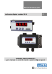
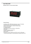
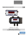
Operating instructions
Digital indicator model DI10
14023439.01 • V1.0 • 10/2011
Digital indicator model DI10
for panel mounting or wall mounting
GB
GB
Operating instructions model DI10 page 1 - 36
© 2010 WIKA Alexander Wiegand SE & Co. KG
All rights reserved.
WIKA® is a registered trademark in various countries.
Prior to starting any work, read the operating instructions!
Keep for later use!
2
WIKA operating instructions digital indicator DI10
Contents
1
2
General information ................................................................................4
Safety .......................................................................................................5
2.1
2.2
2.3
2.4
3
4
Intended use ........................................................................................5
Personnel qualification.........................................................................7
Special hazards ...................................................................................7
Labelling / Safety marks ......................................................................8
Specifications ..........................................................................................9
Design and function ..............................................................................11
4.1 Short description................................................................................11
4.2 Scope of delivery ...............................................................................11
5
Transport, packaging and storage .......................................................12
5.1 Transport ...........................................................................................12
5.2 Packaging..........................................................................................12
5.3 Storage ..............................................................................................12
6
Commissoning, operation ....................................................................13
6.1
6.2
6.3
6.4
6.5
6.6
6.7
7
Mounting............................................................................................13
Electrical connection ..........................................................................14
Function and operation description ....................................................17
Setting up the device .........................................................................18
Extended parameterization ................................................................21
Functional principle of the setpoints ...................................................27
Default values ....................................................................................28
Maintenance and cleaning ....................................................................30
7.1 Maintenance ......................................................................................30
7.2 Cleaning ............................................................................................30
8
9
Faults .....................................................................................................30
Dismounting, return and disposal .......................................................31
9.1 Dismounting ......................................................................................31
9.2 Return................................................................................................32
9.3 Disposal.............................................................................................32
10 Appendix: Declaration of conformity...................................................33
Declarations of conformity can be found online at www.wika.com.
WIKA operating instructions digital indicator model DI10
3
1 General information
1 General information
The instrument described in the operating instructions has been
designed and manufactured using state-of-the-art technology.
All components are subject to stringent quality and environmental
criteria during production. Our management systems are certified to
ISO 9001.
These operating instructions contain important information on handling
the instrument. Working safely requires that all safety instructions and
work instructions are observed.
Observe the relevant local accident prevention regulations and general
safety regulations for the instrument's range of use.
The operating instructions are part of the instrument and must be kept
in the immediate vicinity of the instrument and readily accessible to
skilled personnel at any time.
Skilled personnel must have carefully read and understood the
operating instructions, prior to beginning any work.
The manufacturer's liability is void in the case of any damage caused by
using the product contrary to its intended use, non-compliance with
these operating instructions, assignment of insufficiently qualified skilled
personnel or unauthorised modifications to the instrument.
The general terms and conditions, contained in the sales
documentation, shall apply.
Subject to technical modifications.
Further information:
- Internet address:
- Relevant data sheet:
- Application consultant:
4
www.wika.de / www.wika.com
AC 80.06
Tel.: (+49) 9372/132-0
Fax: (+49) 9372/132-406
E-Mail: [email protected]
WIKA operating instructions digital indicator DI10
2 Safety
Explanation of symbols
WARNING!
... indicates a potentially dangerous situation that can result
in serious injury or death, if not avoided.
Information
... points out useful tips, recommendations and information
for efficient and trouble-free operation.
DANGER!
...identifies hazards caused by electric power. Should the
safety instructions not be observed, there is a risk of serious
or fatal injury.
2 Safety
WARNING!
Before installation, commissioning and operation, ensure that
the appropriate instrument has been selected in terms of
measuring range, design and specific measuring conditions.
Non-observance can result in serious injury and/or damage
to equipment.
Further important safety instructions can be found in the
individual chapters of these operating instructions.
2.1 Intended use
The device is designed for the evaluation and display of current loop signals.
With the setpoints, it is possible to perform simple control tasks (only possible
for devices with setpoints).
The instrument has been designed and built solely for the intended use
described here, and may only be used accordingly.
WIKA operating instructions digital indicator model DI10
5
2 Safety
Please read the following safety advice and the assembly before installation
and keep it for future reference.
If the instrument is transported from a cold into a warm environment, the
formation of condensation may result in the instrument malfunctioning. Before
putting it back into operation, wait for the instrument temperature and the
room temperature to equalise.
Notes on installation
There must be no magnetic or electric fields in the vicinity of the device,
e.g. due to transformers, mobile phones or electrostatic discharge.
Do not install inductive consumers (relays, solenoid valves etc.) near
the device and suppress any interference with the aid of RC spark
extinguishing combinations or free-wheeling diodes.
Keep input, output and supply lines separate from one another and do
not lay them parallel with each other. Position “go” and “return lines”
next to one another. Where possible use twisted pair. So, you receive
best measuring results.
Screen off and twist sensor lines. Do not lay current-carrying lines in the
vicinity. Connect the screening on one side on a suitable potential
equaliser (normally signal ground).
The device is not suitable for installation in areas where there is a risk
of explosion.
Any electrical connection deviating from the connection diagram can
endanger human life and/or can destroy the equipment.
The terminal area of the devices is part of the service. Here electrostatic
discharge needs to be avoided. Attention! High voltages can cause
dangerous body currents.
Galvanic insulated potentials within one complex need to be placed on
a appropriate point (normally earth or machines ground). So, a lower
disturbance sensibility against impacted energy can be reached and
dangerous potentials, that can occur on long lines or due to faulty
wiring, can be avoided.
The manufacturer shall not be liable for claims of any type based on
operation contrary to the intended use.
6
WIKA operating instructions digital indicator DI10
2 Safety
2.2 Personnel qualification
WARNING!
Risk of injury should qualification be insufficient!
Improper handling can result in considerable injury and
damage to equipment.
The activities described in these operating instructions
may only be carried out by skilled personnel who have
the qualifications described below.
Keep unqualified personnel away from hazardous areas.
Skilled electrical personnel
Skilled electrical personnel are understood to be personnel who, based on
their technical training, knowledge of measurement and control technology
and on their experience and knowledge of country-specific regulations,
current standards and directives, are capable of carrying out work on
electrical systems and independently recognising and avoiding potential
hazards.
The skilled electrical personnel have been specifically trained for the work
environment they are working in and know the relevant standards and
regulations.
The skilled electrical personnel must comply with current legal accident
prevention regulations.
2.3 Special hazards
DANGER!
Danger of death caused by electric current.
Upon contact with live parts, there is a direct danger of
death.
Electrical instruments may only be installed and mounted
by skilled electrical personnel.
Operation using a defective power supply unit (e.g. short
circuit from the mains voltage to the output voltage) can
result in life-threatening voltages at the instrument!
WARNING!
Do NOT use this product as safety or emergency stopping
device, or in any other application where failure of the
product could result in personal injury or material damage.
Failure to comply with these instructions could result in
death or serious injury and material damage.
WIKA operating instructions digital indicator model DI10
7
2 Safety
2.4 Labelling / Safety marks
Product label
Explanation of symbols
Before mounting and commissioning the instrument, ensure
you read the operating instructionns!
CE, Communauté Européenne
Instruments bearing this mark comply with the relevant
European directives.
8
WIKA operating instructions digital indicator DI10
3 Specifications
3 Specifications
Specifications
Display
Principle
Character size
Indication range
Display rate
Memory
Input
Number and type
Accuracy
Measuring time
Voltage drop
Power supply
Electrical connection
{Switching outputs}
Number and type
Display
Material
Ingress protection
Dimensions
Mounting
{Wall mounting
enclosure}
Material
Ingress protection
Dimensions
Cable gland
Mounting
7-segment LED, red, 4-digit
14 mm
-1999 … +9999
0.1….10 sec
Flash memory (independent of power supply),
data retension > 100 years
1 current input 4…20 mA
± 0.3 % ± 1 Digit
0.1…10 sec
approx. DC 5.1 V, max. 150 mW
{approx. DC 8.0 V for option with switching
outputs, max. 200 mW}
Not required, since the indicator is powered by
the 4…20 mA loop
plug-in terminal, wire cross-section up to 2.5
mm²
2 PhotoMOS outputs, potential free
max. AC/DC 30 V, max. 0.4 A
PC polycarbonate, black
Front: IP 65, rear: IP 00
96 x 48 x 45 mm (w x h x d) including plug-in
terminals
snap-in screw element for wall thickness up to
3 mm
ASA, black, PG gland
IP 65
160 x 90 x 60 mm (w x h x d)
Cable diameter: 4.0…8.0 mm
fixing holes for screws
WIKA operating instructions digital indicator model DI10
9
3 Specifications
Permissible ambient conditions
Operating temperature
0…60 °C
Storage temperature
-20…80 °C
Humidity
0…80 % relative humidity, non-condensing
CE conformity
EMC directive
2004/108/EC, EN 61326 emission (group 1,
class B) and interference immunity (industrial
application)
{ } Items in curved brackets are optional extras for additional price.
For further specifications see WIKA data sheet AC 80.06 and the order
documentation.
Operating elements
10
WIKA operating instructions digital indicator DI10
4 Design and function
4 Design and function
4.1 Short description
The device is designed for the evaluation and display of current loop signals
(4…20 mA). With the setpoints, it is possible to perform simple control tasks
(only possible for devices with setpoints).
The configuration of the device is done with an intuitive menu navigation. The
14 mm characters allow a good read-out of the measuring values.
4.2 Scope of delivery
The scope of delivery is:
Indicator for panel mounting:
Indicator
2 fixing elements
Seal
Operating instructions
Indicator for wall mounting:
Indicator
Operating instructions
Cross-check scope of delivery with delivery note.
WIKA operating instructions digital indicator model DI10
11
5 Transport, packaging and storage
5 Transport, packaging and storage
5.1 Transport
Check instrument for any damage that may have been caused by transport.
Obvious damage must be reported immediately.
5.2 Packaging
Do not remove packaging until just before mounting. Keep the packaging as it
will provide optimum protection during transport (e.g. change in installation
site, sending for repair).
5.3 Storage
Permissible conditions at the place of storage:
Storage temperature: -20 ... +80 °C
Humidity: 0 ... 80 % relative humidity (no condensation)
Avoid exposure to the following factors:
Direct sunlight or proximity to hot objects
Mechanical vibration, mechanical shock (putting it down hard)
Soot, vapour, dust and corrosive gases
Potentially explosive environments, flammable atmospheres
Store the instrument in its original packaging in a location that fulfils the
conditions listed above. If the original packaging is not available, pack and
store the instrument as described below:
1. Wrap the instrument in an antistatic plastic film.
2. Place the instrument, along with shock-absorbent material, in the
packaging.
3. If stored for a prolonged period of time (more than 30 days), place a
bag, containing a desiccant, inside the packaging.
WARNING!
Before storing the instrument (following operation), remove
any residual media. This is of particular importance if the
medium is hazardous to health, e.g. caustic, toxic,
carcinogenic, radioactive, etc.
12
WIKA operating instructions digital indicator DI10
6 Commissoning, operation
6 Commissoning, operation
Please read the safety instructions and installation instructions in chapter 2
before installation and keep this user manual for future reference.
6.1 Mounting
Indicator for panel mounting:
1. After removing the fixing elements, insert the device.
2. Check the seal to make sure it fits securely.
3. Click the fixing elements back into place and tighten the clamping
screws by hand. Then use a screwdriver to tighten them another half a
turn.
CAUTION!
The torque should not exceed 0.1 Nm!
The dimension symbols can be exchanged before
installation via a channel on the side!
WIKA operating instructions digital indicator model DI10
13
6 Commissoning, operation
Indicator for wall mounting:
Fasten the wall mounting enclosure with adequate material (screws) at the
four mounting holes.
Screws are not part of scope of delivery. Please use screws
according to the material of the wall, where you want to install
the enclosure.
For electrical connection pass the cable through the high-strength cable
gland.
Close the enclosure with the attached screws and fasten the screw nut of the
cable gland. So ingress protection IP 65 is reached.
6.2 Electrical connection
device without setpoints
14
WIKA operating instructions digital indicator DI10
6 Commissoning, operation
device with setpoints
For devices with switching outputs please use measuring input Irel+.
Connection examples
The examples show devices with setpoints.
a) Current loop device in combination with a transmitter in current
loop technique:
b) Current loop device in combination with another measuring input
with low burden:
WIKA operating instructions digital indicator model DI10
15
6 Commissoning, operation
c) Current loop device in combination with a 3-wire sensor:
d) Current loop device in combination with a 4-wire sensor:
e) Current loop device with activated outputs DC 24 V (upto 0.4 A)
16
WIKA operating instructions digital indicator DI10
6 Commissoning, operation
6.3 Function and operation description
Operation
The operation is divided into two different levels.
Menu Level: Here it is possible to navigate between the individual
menu items.
Parameterization level: The parameters stored in the menu item can
be parameterized here.
Functions that can be adjusted or changed are always indicated with a
flashing of the display. Adjustments made at the parameterization level
should be always confirmed by pressing the [P] key to save them.
However, the display automatically saves all adjustments and then switches
to operation mode if no further keys are pressed within 10 seconds.
Level
Menu level
Parameterization
level
Button
Description
Change to parameterization level with the
relevant parameters.
For navigation at the menu level.
To confirm the changes made at the
parameterization level.
To change the value or setting.
Example:
WIKA operating instructions digital indicator model DI10
17
6 Commissoning, operation
6.4 Setting up the device
Switching on
Once the installation is complete, you can start the device by applying the
current loop. Check beforehand once again that all the electrical connections
are correct.
Starting sequence
For 1 second during the switching-on process, the segment test (8 8 8 8) is
displayed, followed by an indication of the software type and, after that, also
for 1 second, the software version. After the start-up sequence, the device
switches to operation/display mode.
Standard parameterization
To be able to parameterize the display, press the [P] key in operating mode
for 1 second. The display then changes to the menu level with the first menu
item tYPE.
Menu level Parameterization level
Selection of the input signal, tYPE:
tYPE
4-20
SEnS
There are two measuring input options for the current loop: 420 mA as works calibration (without application of the sensor
signal) and SEnS as sensor calibration (with the sensor
applied). Confirm the selection with [P] and the display
switches back to the menu level.
18
WIKA operating instructions digital indicator DI10
6 Commissoning, operation
Menu level Parameterization level
Setting the measuring range end value, END:
End
8
8
8
8
nOCA
CAL
Set the end value from the smallest to the highest digit with
[▲] [▼] and confirm each digit with [P]. A minus sign can only
be parametrized on the highest value digit. After the last digit,
the display switches back to the menu level.
If SEnS was selected as the input option, you can only select
between nOCA and CAL. With nOCA, only the previously set
display value is taken over, and with CAL, the device takes
over both the display value and the analogue input value.
Setting the measuring range start/offset value, offs:
OFFS
8
8
8
8
nOCA
CAL
Enter the start/offset value from the smallest to the highest
digit [▲] [▼] and confirm each digit with [P]. After the last digit
the display switches back to the menu level.
If SEnS was selected as the input option, you can only select
between nOCA and CAL. With nOCA, only the previously set
display value is taken over, and with CAL, the device takes
over both the display value and the analogue input value.
WIKA operating instructions digital indicator model DI10
19
6 Commissoning, operation
Menu level Parameterization level
Setting the decimal point, dot:
dot
0
0.0
0.00
0.000
The decimal point on the display can be moved with [▲] [▼]
and confirmed with [P]. The display then switches back to the
menu level again.
Setting the display time, SEC:
SEC
0.1
0.9 dann 1.0
10.0
The display time is set with [▲] [▼]. The display moves up in
increments of 0.1 up to 1 second and in increments of 1.0 to
10.0 seconds. Confirm the selection by pressing the [P]
button. The display then switches back to the menu level
again.
Activation / deactivation of the programming lock and
completion of the standard parameterization, run:
run
ULOC
LOC
With the aid of the [▲] [▼] keys, you can choose between the
deactivated key lock ULOC (works setting) and the activated
key lock LOC. Make the selection with [P]. After this, the
display confirms the settings with "- - - -", and automatically
switches to operating mode.
If LOC was selected, the keyboard is locked. To get back into
the menu level, you must press [P] for 3 seconds in operating
mode. You must now enter the CODE (works setting 1 2 3 4)
that appears using the [▲] [▼] keys plus [P] to unlock the
keyboard. FAIL appears if the input is wrong.
20
WIKA operating instructions digital indicator DI10
6 Commissoning, operation
6.5 Extended parameterization
By pressing the [▲] & [▼] buttons during standard parameterization for one
second, the display switches to the extended parameterization mode.
Operation is the same as in standard parameterization.
Menu level Parameterization level
Rescaling the measuring input values, EndA:
EndA
8
8
8
8
With the aid of this function, you can rescale the input value of
4-20 mA (works setting) without applying a measuring signal.
If sensor calibration has been selected, these parameters are
not available.
Rescaling the measuring input values, OFFA:
OFFA
8
8
8
8
With the aid of this function, you can rescale the input value of
4-20 mA (works setting) without applying a measuring signal.
If sensor calibration has been selected, these parameters are
not available.
Setting the tare /offset value, tArA:
tArA
0
0
0
0
The given value is added to the linerarized value. In this way,
the characteristic line can be shifted by the selected amount.
WIKA operating instructions digital indicator model DI10
21
6 Commissoning, operation
Menu level Parameterization level
Zero point tranquilization, ZErO:
ZErO
0
0
With zero point tranquilization, a value range around zero can
be preselected at which the display shows zero. If, for
example, a 10 is set, the display would show a zero in the
range from -10 to +10 and continue below it with -11 and
above it with +11.
MIN/MAX value inquiry - Assignment of key functions,
tAST:
tASt
EHEr
LI.12
no
Here, you can enter for the operating mode either a MIN/MAX
value inquiry or a threshold value correction on the arrow
keys.
If the MIN/MAX memory is activated with EHEr, the measured
MIN/MAX values will be saved during operation and can be
called up via the arrow keys [▲] [▼]. The values are lost if the
device is restarted.
If the threshold value correction LI.1 is selected, the limit
values can be changed during operation without hindering the
operating procedure.
If no is parameterized, the arrow keys [▼] [▲] have no
function in operating mode.
Flashing of display, FLAS:
FLAS
LI-1
LI-2
LI.12
no
Here, flashing of the display can be added as an extra alarm
function, either to the first limit value (select: LI-1), the second
limit value (select: LI-2) or to both limit values (select: LI.12).
With no (works setting), no flashing is assigned at all.
22
WIKA operating instructions digital indicator DI10
6 Commissoning, operation
6.5.1 Limit values, limits, hysteresis
Menu level Parameterization level
Limit values / Limits, LI-1:
LI-1
0
0
0
0
For both limit values, two different values can be
parameterized. With this, the parameters for each limit value
are called up one after the other.
Hysteresis for limit values, HY-1:
HY-1
0
0
0
0
For both limit values, a hysteresis function exists that reacts
according to the functional principle (operating current /
quiescent current).
Function if display falls below / exceeds limit value, Fu-1:
Fu-1
HIgH
Louu
(Low)
To indicate if the value falls below the lower limit value, Louu
can be selected (LOW = lower limit value) and if it goes above
the upper limit value, HIgH can be selected (HIgH = upper
limit value). LOW corresponds to the quiescent current
principle and HIgH to the operating current principle.
WIKA operating instructions digital indicator model DI10
23
6 Commissoning, operation
Menu level Parameterization level
Limit value /Limits, LI-2:
LI-2
0
0
0
0
For both limit values, two different values can be
parameterized. With this, the parameters for each limit value
are called up one after the other.
Hysteresis for limit values, HY-2:
HY-2
0
0
0
0
For both limit values, a hysteresis function exists that reacts
according to the functional principle (operating current /
quiescent current).
Function if display falls below / exceeds limit value, FU-2:
Fu-2
HIgH
Louu
(Low)
To indicate if the value falls below the lower limit value, Louu
can be selected (LOW = lower limit value) and if it goes above
the upper limit value, high can be selected (HIGH = upper limit
value). LOW corresponds to the quiescent current principle
and HIGH to the operating current principle.
24
WIKA operating instructions digital indicator DI10
6 Commissoning, operation
Menu level Parameter-Ebene
Setting the code, CODE:
CodE
1
2
3
4
With this setting, it is possible to select an individual code
(works setting 1 2 3 4) for locking the keyboard. To
locl/release the key, proceed according to menu item run.
WIKA operating instructions digital indicator model DI10
25
6 Commissoning, operation
6.5.2 Additional setpoints
Menu level Parameter-Ebene
Setpoints - Number of additional setpoints, SPCt:
SPCt
0
In addition to the start and end value, 8 extra setpoints can be
defined to linearize non-linear sensor values. Only the
activated setpoint parameters are displayed.
Display values for setpoints dIS1 … dIS8:
dIS1
8
8
8
8
nOCA
CAL
Under this parameter the value of the setpoints is defined.
With sensor calibration, as with end value/offset, you will be
asked at the end whether a calibration should be made.
Analogue values for setpoints INP1 … INP8:
InP1
0
0
0
0
The setpoints are only displayed with the works calibration (420 mA). Here, the desired analogue values can be freely
selected. The input of constantly rising analogue values must
be carried out by the customer/user.
26
WIKA operating instructions digital indicator DI10
6 Commissoning, operation
6.6 Functional principle of the setpoints
Operating current
The setpoint S1-S2 is
off below the threshold
and on reaching the
threshold.
Quiescent current
The setpoint S1-S2 is on
below the threshold and
switched off on reaching
the threshold.
Alarms / optical setpoint display
An activated setpoint can be optically indicated by flashing of the 7-segment
display.
Functional principle of the alarms
Threshold
Threshold/limit value for switch over
Hysteresis
Width of the window between the thresholds
Operating principle
Operating current / quiescent current
WIKA operating instructions digital indicator model DI10
27
6 Commissoning, operation
6.7 Default values
Reset to default values
To return the unit to a defined basic state, a reset can be carried out to the
default values. The indicator must be in “ULOC” mode. An accidental reset
during operation is avoided..
The following procedure should be used:
Switch off the power supply
Press button [P]
Switch on loop current (approx. 3.8 mA) and press [P]-button until
„- - - -“ is shown in the display.
With reset, the default values of the program table are loaded and used for
subsequent operation. This puts the unit back to the state in which it was
supplied.
Caution!
28
All application-related data are lost.
WIKA operating instructions digital indicator DI10
6 Commissoning, operation
Default values
PN
0
1
2
3
13
50
1 bin
2 bin
4
5
6
59
61
62
63
71
72
73
51
100
101 A
101 B
102 A
102 B
103 A
103 B
104 A
104 B
105 A
105 B
106 A
106 B
107 A
107 B
108 A
108 B
Parameter Menu items
tYPE
4-20
SEnS
End
-1999
to
OFFS
-1999
to
dot
0000
to
SEC
0.1
bis
run
ULOC
LOC
OFFA
-19.99
to
EndA
-19.99
to
tArA
-1999
to
ZErO
00
to
tASt
No
EHtr
FLAS
No
LI-1
LI-1
-1999
to
HY-1
0000
to
Fu-1
Louu
HIgH
LI-2
-1999
to
HY-2
0000
to
Fu-2
Louu
HIgH
CodE
0000
to
SPCt
0
to
dIs1
-1999
to
InP1
-1999
to
dIs2
-1999
to
InP2
-1999
to
dIs3
-1999
to
InP3
-1999
to
dIs4
-1999
to
InP4
-1999
to
dIs5
-1999
to
InP5
-1999
to
dIs6
-1999
to
InP6
-1999
to
dIs7
-1999
to
InP7
-1999
to
dIs8
-1999
to
InP8
-1999
to
9999
9999
0.000
10.0
99.99
99.99
9999
99
LI.12
LI-2
9999
9999
9999
9999
9999
8
9999
9999
9999
9999
9999
9999
9999
9999
9999
9999
9999
9999
9999
9999
9999
9999
WIKA operating instructions digital indicator model DI10
Default
SEnS
2000
0400
0
1.0
ULOC
04.00
20.00
0000
00
No
LI12
no
0800
0000
HIgH
1200
0000
HIgH
1234
0
29
8 Faults
7 Maintenance and cleaning
7.1 Maintenance
This instrument is maintenance-free.
Repairs must only be carried out by the manufacturer.
7.2 Cleaning
CAUTION!
Before cleaning, correctly disconnect the instrument
from the mains.
Clean the instrument with a moist cloth.
Electrical connections must not come into contact with
moisture.
For information on returning the instrument see chapter "9.2
Return".
8 Faults
Fault
The display of the device is dark
Solution
Check the current loop current of the
device.
Please contact the manufacturer if
errors of this kind occur.
The device shows 4 bars in the upper Displayed overflow at exceedance
part of the display
of display/measuring range
The device shows 4 bars in the lower Displayed overflow at undershooting
part of the display
of display/measuring range
The device shows „Err2“ (Error 2)
During parameterization current <
3,5 mA
30
WIKA operating instructions digital indicator DI10
9 Dismounting, return and disposal
CAUTION!
If faults cannot be eliminated by means of the measures
listed above, the instrument must be shut down immediately,
and it must be ensured that pressure and/or signal are no
longer present, and it must be prevented from being
inadvertently put back into service.
In this case, contact the manufacturer.
If a return is needed, please follow the instructions given in chapter "9.2
Return".
9 Dismounting, return and disposal
WARNING!
Residual media in dismounted instruments can result in a
risk to persons, the environment and equipment. Take
sufficient precautionary measures.
9.1 Dismounting
To dismount the instrument, do the following steps:
Indicator for panel mounting:
1. Open the clamping screws and remove the fixing elements.
2. Remove the instrument and seal from panel cutout.
Indicator for wall mounting:
For dismounting the indicator open the four fastening screws of the enclosure
and remove it.
WIKA operating instructions digital indicator model DI10
31
9 Dismounting, return and disposal
9.2 Return
WARNING!
Strictly observe when shipping the instrument:
All instruments delivered to WIKA must be free from any kind
of hazardous substances (acids, bases, solutions, etc.).
When returning the instrument, use the original packaging or a suitable
transport package.
Enclose the completed return form with the instrument.
The return form is available on the internet:
www.wika.de / Service / Return
9.3 Disposal
Incorrect disposal can put the environment at risk.
Dispose of instrument components and packaging materials in an
environmentally compatible way and in accordance with the country-specific
waste disposal regulations.
32
WIKA operating instructions digital indicator DI10
10 Appendix: Declaration of conformity
10 Appendix: Declaration of conformity
WIKA operating instructions digital indicator model DI10
33
10 Appendix: Declaration of conformity
34
WIKA operating instructions digital indicator DI10
10 Appendix: Declaration of conformity
WIKA operating instructions digital indicator model DI10
35
WIKA global
WIKA subsidiaries worldwide can be found online at www.wika.com.
WIKA Alexander Wiegand SE & Co. KG
Alexander-Wiegand-Straße 30
63911 Klingenberg • Germany
Tel. (+49) 9372/132-0
Fax (+49) 9372/132-406
E-Mail [email protected]
www.wika.de
36
WIKA operating instructions digital indicator DI10