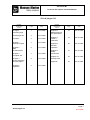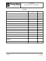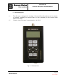
1
AIS Tester M1
Technical Description and Guide Manual
Malfunction diagnostic
and control device of
AIS stations class A
AIS TESTER M1
Technical Description and Guide Manual
Версия – 1.0
AIS Tester M1
Technical Description and Guide Manual
Date
Signature
accompanying
document entry
number
Document number
Canceled
new
Page number
changed
Chapter Subdivision
Article number
Changes.
Changes journaling page
Page 1
Changes journaling pages
09.12.2008
AIS Tester M1
Technical Description and Guide Manual
Actual pages list
Chapter
Subdivision
Article
Page
Date
Changes
journaling page
1
09.12.2008
Actual pages list
2
09.12.2008
Contents
3
09.12.2008
Chapter 1
General Purpose
4
09.12.2008
Chapter 2
Main
Characteristics
6
Chapter 3
Complete Set
Chapter
Subdivision
Article
Page
Date
Chapter 6
Measurement of
AIS parameters
16
09.12.2008
Chapter 7
Tester’s
calibration
19
09.12.2008
20
09.12.2008
09.12.2008
Chapter 8
General
operation
21
09.12.2008
7
09.12.2008
Chapter 9
Safety
precautions
09.12.2008
8
09.12.2008
Chapter 10
Storage rules
22
Chapter 4
Device Operation
and Description
Appendix
23
09.12.2008
Chapter 5
Operation
9
09.12.2008
Page 2
Actual pages list
09.12.2008
AIS Tester M1
Technical Description and Guide Manual
Contents
Title
Item No
Page
Changes journaling page
1
Actual pages list
2
Contents
3
General Purpose
1
4-5
Main Characteristics
2
6
Complete Set
3
7
Device Operation and Description
4
8
Operation procedures
5
9-15
AIS measurement parameters settings
6
16-18
Tester’s calibration
7
19
General operation
8
20
Safety precautions
9
21
Storage rules
10
22
Appendix:
Appendix 1. Tester’s main menu structure
23
Page 3
Contents
09.12.2008
AIS Tester M1
Technical Description and Guide Manual
1. General purpose
1.1
1.2
The AIS tester is designed for checking of A class AIS mobile stations and it is suitable
for express checking and annual tests as well (according to the circular letter
MSC.1/Circ.1252).
General view of the tester is represented on the fig.1-1
Fig. 1-1. General view
Item 1
Page 4
General Purpose
09.12.2008
AIS Tester M1
Technical Description and Guide Manual
1.3
AIS TESTER operates on a frequencies of AIS channel 1, channel 2 and DSC – channel
70. It’s designed according to the ITU Р M-1371-3, and IEC 61993-2 standards as
technical equipment for AIS blocks and stations mounting accuracy testing on a vessel.
Checking of the testable equipment is to carry out using the cable with included
attenuator or by means of antenna through broadcast.
TESTER is controlled with the keyboard and graphic LCD-display with screen resolution
128*64 dpi. Using the main menu one can perform full automatic checking. Testing
results are shown on the display and saved in nonvolatile memory unit. TESTER renders
possible to save four self-contained measuring sessions each of which easily retrieve to
a PC later using included utility programme.
To use TESTER there’s no need to synchronize with GNSS (Global Navigation Satellite
System) – TESTER uses suitable slot synchronization technique which is not supposed
to necessarily get GNSS timing signals. For general generated VDL and request
information applied RATDMA ultrashort waves access
method of procedure.
One can check pilot plug and external sensor with the TESTER because of using this
equipment as terminal.
One doesn’t need to posses some extra knowledge to operate the TESTER – all you
have to do is to make a thorough examination of this user manual. TESTER can be
programmed in any suggested conditions and can be simply upgraded.
1.4
TESTER allows to:
- Measure AIS frequencies (on channels 1,2);
- Measure or estimate the AIS transmitted power;
- Decoding of AIS messages;
- DSC polling information passing (channel 70);
- check AIS answer to so called “virtual vessel”
1.5
Under the terms of operation TESTER is to use at a temperature range of + 5 оС to + 45
о
С. and relative humidity 95% depending on the LCD type.
1.6
The TESTER is powered supply by four 1,5V AA batteries or external power supply unit
with 4,2….6V and system load current no less than 500 mA, which is connected to the
TESTER via USB port (USB network adapter or PC USB port).
Item 1
Page 5
General Purpose
09.12.2008
AIS TESTER M1
Technical Description and Guide Manual
2. Main characteristics:
2.1
AIS operational frequencies are: channel 1 - 161,975 MHz ;
channel 2 - 162,025 MHz.
2.2
DSC operational frequency channel 70 - 156,525 MHz.
2.3
Setting accuracy of output frequency – no less than ±1ppm.
2.4
Output power of AIS channel 1,2 and channel 70 DSC no less than
mW.
2.5
AIS modulation - FM-GMSK.
2.6
AIS channel band rate - 9600 Baud.
2.7
DSC channel band rate - 1200 Baud.
2.8
Tester provides carrier frequency measurement in range of 156-162MHz within the
accuracy ± 99 Hz.
2.9
Input\Output resistance - - (50 ± 1.5) Ohm.
(-7) dBm or 100
ATTENTION! Input attenuator signal capacity in continuous mode must be not more then
10 W.
2.10
TESTER allows to save four self-contained measuring sessions in nonvolatile memory
unit. One measurement cycle time requires about 10 min.
2.11
TESTER power supply requires four 1,5W AA batteries or external power supply of
4,2….6 W and power system load current no less than 500 mA which is connected to
the TESTER via USB port (USB network adapter or PC USB port).
2.12
TESTER useful current from inner battery:
-
light-off stand-by mode – not above 150 mA
light-up stand-by mode - not above 200 mA
light-off measurement mode - not above 350 mA
2.13
Approximate continuous operation time using the battery – about 5 hours.
2.14
TESTER displays internal battery voltage with accuracy ± 5%.
Item 2
Page 6
General Purpose
09.12.2008
AIS TESTER M1
Technical Description and Guide Manual
3. Complete set
3.1 Complete set of the TESTER includes:
№
1
2
3
4
5
6
7
8
9
10
Item
AIS Tester
Attenuator
PC Cable (USB A – USB A 1.5м)
PC Cable (DB9 - NMEA )
RF Cable TNC-TNC
RF Cable BNC-BNC
RF Connector BNC-UHF
Technical Description and User Manual
Package
Software and software user’s guide manual
amt
1
1
1
1
1
1
1
1
1
Notification
optional
* Updated software can be
downloaded at our website
•
•
* The updated version of software can be downloaded at our website :
http://gmdsstesters.com/downloads/ais_software.zip
** The FTDI driver is required for connection with PC. FTDI driver can be downloaded at our website:
http://gmdsstesters.com/downloads/drivers_FTDI.rar
Serial Number: _____________________________________
Issue date: ________________________________________
Acceptance date: ___________________________________
Раздел 3.
Стр.7
Комплектность
09.12.2008
AIS TESTER M1
Technical Description and Guide Manual
4. TESTER operation and description.
4.1 The measurement of AIS parameters can be carried out by means of the cable and
attenuator (with attenuation 40 dB) or by the outside antenna. The high-frequency cable is to be
connected to the according input on the front panel (fig. 5-1).
4.2 The measurement can be carried out independently – in this case TESTER supplies by
means of inner battery units, or in steady-state conditions – by means of power-supply source.
4.3 The signal from the testable equipment goes to the duplexer by means of the attenuator
(or antenna and broadcast), and after being filtrated it goes to the two separate receivers which
get signals of different frequency. In this case the receiver of signal is a double-conversion
superheterodyne. The first heterodyne has fixed frequency, but the second one has tunable
frequency which helps to adjust to different frequency range. Both of this heterodynes has
phase-locked-loop frequency control – it means that main frequency is the fixed frequency of
temperature-compensated reference-frequency generator. First intermediate frequency channel
is 6020 - 6040 kHz – it includes an intermediate-frequency amplifier, a log detector of receiving
signal level, a ratio detector, that forms signal of phase rebounds – they means bipolar pulses
that corresponds to the phase translation of phase-shift keyed signal input. This phase
translation of phase-shift keyed signal input is needed to decode information and phase
deviation calculation in main controller.
4.4 The signal receiver is a superheterodyne with a single frequency changing and a
heterodyne that included in phase-locked-loop frequency control circuit. In channel are included:
heterodyne, mixer, intermediate-frequency amplifier, and a log detector of receiving signal level.
This detector detects amplitude modulation signal and reports a sweep signal to a main
controller with the amplitude which is proportional to the receiving signal level.
4.5 All the changes are performed by the main controller which in it’s turn controlled by the
frequency of high-stable reference-frequency generator. Main controller plug-in besides AIS
signal processing maintains the indicator, keyboard and acoustic controller work. Besides, main
controller energize only the necessary units – it saves energy greatly – and also it imports data
to the PC using interface level transducer RS-232.
4.6
level.
Reference supply source is used to improve measurement accuracy received signal
Item 4
Page 8
Tester operation and description
09.12.2008
AIS TESTER M1
Technical Description and Guide Manual
5
Operation
5.1
Operation and connection control.
5.1.1
On the front panel of the tester are LCD indicator with the screen resolution 128*64 and
keyboard. (Fig. 5-1).
5.1.2
One can turn TESTER using top-right ON button, and turn it off holding the same
button about 5 seconds. (Fig. 5-1).
5.1.3
Navigation buttons ←, →, ↓, ↑, ESC, ENT will help to choose menu options and to
execute selected operations, and also for confirmation/backtracking of the selected
operation. (Fig. 5-1).
5.1.4
F1 и F2 buttons in main menu will turn on and turn off LCD lighting respectively.
Sometimes this buttons control another functions – such cases will be described below.
Fig. 5-1
5.1.5
MENU button helps to get quick entrance to the main menu.
Item 5
Page 9
Operation procedures
09.12.2008
AIS TESTER M1
Technical Description and Guide Manual
There is HF input for the antenna or attenuator connection on the top of the TESTER’s case. On
the bottom panel of the device is allowed additional slot for PC or power supply adapter
connection. (Fig. 5-1).
5.2
Turning ON/OFF
5.2.1
Turn the device on by pressing and holding ON button till sound signal and the moment
when main screen picture will appear on the display (2-3 sec.):
Musson Marine Ltd.
AIS Tester
Ser.No. xxxx
Soft.rev.1.0.
hh:mm
dd.mm.20yy
After that, release ON button. Pressing and holding ON button within 3…5 sec. will
turn the TESTER off.
5.3
TESTER menu.
By pressing MENU button one can reach the following main menu :
AIS Test
Setup
Link PC
Manufacturer Test
Tester main menu structure is represented in Appendix 1. By using buttons ↑ (up) и ↓
(down) you can execute vertical movement.
Using the ENT button one can enter the main menu sections. To exit the menu
sections use the ESC button.
Main menu has four sections:
AIS Test – AIS equipment testing;
Setup - tester parameters settings ;
Link PC – uploading testing results to the PC and user profile download, where are all
the AIS data to AIS channel transfer contained;
Manufacturer Test - manufacturer technical menu;
Each section has its own subsections. User moves among the subsections using the
same buttons as for the moving in main menu.
Use the MENU button to go back to main menu.
5.3.1
AIS Test Menu
Item 5
Page 10
Operation procedures
09.12.2008
AIS TESTER M1
Technical Description and Guide Manual
AIS Test Menu contains the following sections:
● AIS Monitor
●
●
●
●
Ship Emulation
Tx/Rx Message 3
Tx/Rx Message 5
Polling DSC
● Receive NMEA
- continuous input and upload all the AIS information
transferring on the ultra-short waves channels;
- virtual vessel emulation;
- report 3 request and reception;
- report 5 request and reception;
- DSC polling information request and reception on the
channel 70;
- NMEA statement reception and indication on the LCD.
5.3.1.1 AIS Monitor
In this mode tester receives and indicates on the LCD all the AIS reports. As for
example:
AIS Monitor
RxA ID 1 273000000
dF +00045 Hz
RSSI 12,50 W
Slot:xxxx Sync OK
The second line indicates:
- The channel that receives progress report – A or B;
- Report number, according to М.1371-3 (ID x), where x-from 1 to 26ти;
- Vessel MMSI, which transferred the report.
The third line indicates frequency deviation dF (Hz).
The fourth – received signal power (W).
The fifth – the slot number и AIS station controller slot synchronization result.
Synchronization state changes from BAD to OK approximately after 3 or 4 received
reports.
5.3.1.2 Ship Emulation
Entering the menu user should pick up the channel for testing (A or B).
Virtual vessel emulation is performed as following:
First Report 1 including TESTER MMSI and position data of the vessel (with fractional
change about 150 meters) heads to the vessel from which in Menu AIS Monitor was
received position report (Report 1…3).
Then on the tested station CPM appears virtual image (a vessel) which has slightly
different position comparing to the tested station.
After pressing the ENTER button a message “Wait !” will appear on the screen. The
report transmission will be performed after the sound signal.
5.3.1.3 Tx/Rx Message 3
Item 5
Page 11
Operation procedures
09.12.2008
AIS TESTER M1
Technical Description and Guide Manual
As in previous case, entering the menu user should pick up the channel for testing (A
or B).
After pressing the ENTER button all the testing information will appear on the screen:
Tx/Rx Message 3
- request for transferring the report 3;
Channel A
- request will be performed on the A channel;
To: 273 000 000 - MMSI of acquire station,,,
If needed MMSI of acquire station can be edited – to do this press the button “→” ; and
then use the buttons “↑”, “↓” to change the light-up position and use the buttons “←”, “→”
to pick up the required position.
If MMSI corresponds to the tested station – press the ENTER button once more to check
the information – then press the ENTER button again – in this case user has to hear
sound signal and to see a message “Wait !” on the screen. After the sound signal
(about 3-4 sec.) the request will be transferred – Report 15 to the tested station – then
tester will be switched automatically to the receiving mode – in this case all the reports
except the Report 3 will be ignored. Otherwise acquire report may be deleted by another
one which is transferred by the schedule.
Received Report 3 is shown in the following way:
Tx/Rx Message 3
- Report 3 request;
RxA ID 3 273 000 000
- Report 3 is received on channel A;
Long. ¤ 033°29,2448 E
- longitude of the tested station;
Lat.
¤ 44°35,3342 N
- latitude of the tested station.
5.3.1.4 Tx/Rx Message 5
Pick up the channel for testing (A or B).
After pressing the ENTER button all the information will be displayed on the screen:
Tx/Rx Message 5
Channel B
To: 273 000 000
- request for Report 5 transferring;
- request will be performed on channel A;
- MMSI of acquire station,,,
If needed MMSI of acquire station can be edited – to do this press the button “→” ; and
then use the buttons “↑”, “↓” to change the light-up position and use the buttons “←”, “→”
to pick up the required position.
If MMSI corresponds to the tested station – press the ENTER button once more to check
the information – then press the ENTER button again – in this case user has to hear
sound signal and to see a message “Wait!”on the screen. After the sound signal (about
3-4 sec.) the request will be transferred – Report 15 to the tested station – then tester
will be switched automatically to the receiving mode – in this case all the reports except
the Report 5 will be ignored. Otherwise acquire report may be deleted by another one
which is transferred by the schedule.
Item 5
Page 12
Operation procedures
09.12.2008
AIS TESTER M1
Technical Description and Guide Manual
Received Report 3 is shown in the following way :
Tx/Rx Message 5
RxB ID 5 273 000 000
Call
sign @@@@@@@
Name @@@@@@@@@@
@@@@@@@@@@
- Report 5 request;
- Report 5 is received on channel B;
- call sign of the tested vessel;
- the tested vessel name.
5.3.1.5 Polling DSC
Entering this section of the menu user will see the following information:
Polling DSC
- routine work
To : 273 000 000
- MMSI of acquire station.
Wait !
MMSI of acquire station is taken from the report which was received in AIS Monitor
mode! If MMSI corresponds to the tested stations then press the ENTER button – then
after the sound signal request will be transferred through DSC channel. Tester will be
switched automatically to the callback report receiving mode through DSC channel! In
this case will be set 20 sec. countdown timer – time maximum for the AIS station to
respond. After the callback report receiving all decoded information will be shown on
the screen:
Polling DSC
- routine work;
MMSI 273 000 000
Ship name :
xxxxxxxxxx
- MMSI of responding station;
- the vessel name.
The following DSC report is transferring as a request согласно according to
ITU-R M.825-3:
120, 120
Format specifier – Individual call
27,30,00,00,00
MMSI requested station
103
Category – Information
20,19,99,99,90
Self identification = tester’s MMSI no.
111
Message – Report ship’s name/identification
117
End of sequence – Ack.RQ
xxx
ECC – modulus-2 checsum
117,117
End of sequence – Ack.RQ.
5.3.1.6 Receive NMEA
In this menu section user can see all the information that goes to ports of AIS station,
including Pilot Plug. Set the data interchange speed - 38 400 baud. In case if user
needs to test sensors operation - 4800 baud.
TESTER allows to connect exit points with physical layers RS 422 and RS 232 as
well. Interconnect protocol in this case will be NMEA 0183
(MЭК 61 162-1).
Item 5
Page 13
Operation procedures
09.12.2008
AIS TESTER M1
Technical Description and Guide Manual
5.3.2.
Setup Menu
Setup menu contains the following sections:
- optional;
- optional;
- go back to the main screen picture.
Location Source
View Profile
Soft rev.
5.3.2.1
Soft rev.
After entering SOFT Rev. menu section appears the main screen picture, then
using the ”→” (right) button user can entrance date and time settings menu.
To set time and date use the “↑” (up) button - to pick the required position use “→”
(right) button. Press ENTER after all the settings.
5.3.3
Link PC Menu
Link PC menu contains the following sections:
Save Profiles
Load Profiles
- transfer data to the PC;
- upload data from PC (this option is presently unavailable).
5.3.3.1 Save Profiles Section
Entering this section user sees the following screen information:
PRESS
*DOWNLOAD*
BUTTON
IN YOUR
SOFTWARE
Tester connects to the PC by the integrated USB bridge – UART (USB Serial Converter)
manufactured by FTDI - FT232R. Free drivers by FTDI create virtual COM-port, which
provides this connection. To create this connection user should install program drivers
by FT232R.
Program package includes:
■
AIST_software –ZIP manufacturer program archive;
■
CDM 2.04.16 – drivers folder for FT232R;
■
Windows_XP_Installation_Guide – detailed users guide for correct driver
installation.
The recommended installation procedure is following:
1.
dearchive ZIP archive to the separate folder on the PC hard disk;
2.
launch the program;
3.
connect the tester to the Pc using the USB – cord from the tester set and turn on
the device.
Item 5
Page 14
Operation procedures
09.12.2008
AIS TESTER M1
Technical Description and Guide Manual
4.
then the message that the new USB device was found will appear on the screen;
as a drivers installation resource select CDM 2.04.16 folder from the program package;
5.
enter the tester PC LINK > Save Profiles menu section and initialize AIST
software .
5.3.4 Manufacturer Test Menu
This menu contains following sections :
Ubat
- voltage of power supply measurement;
RF Test
- HF hosts testing;
Power
- power meter calibration;
DAC
- HF voltage-control installation;
5.3.4.1 Ubat Section
In this section user can measure and see on the screen source voltage of the tester. If
the source voltage is less than 4,5 W a “battery low” pictogram will appear in the top
right LCD corner. If the source voltage is less than 4,0 W user will see a message:
Replace Battery
- after that tester will be switched off automatically!
5.3.4.2 Don’t change any Power и DAC menu settings – it may cause the device failure!
5.4.
Tester outside power unit operation.
As a TESTER power supply unit use USB adapter which is optional included into the
complete set of the device. Tester can also be power supplied by 220 V AC supply,
and besides, directly from the PC USB port.
Item 5
Page 15
Operation procedures
09.12.2008
AIS TESTER M1
Technical Description and Guide Manual
6.
Measurement of AIS parameters
6.1
General notes of AIS Station.
In this section is described logical operation and criteria set, which are to use during the
checking AIS station A class. They are based upon IMO / IALA recommended guideline – so,
only in this case user can get one-valued and directly treat results while using the AIS Tester
“M1”.
By the primary testing of the just mounted station make sure that AIS equipment is
installed in proper way according to this guidance and manufacturer demands to get
the successful operation of the AIS.
One of the important AIS aspects is its mobility. Together with requesting some certain
operation of AIS Tester (which is expected operation) , AIS carries out an action,
according to AIS protocol of current navigation circumstances (which is unexpected
operation).
6.2
Checking sequence.
6.2.1
Connect the AIS station output to the attenuator input, and attenuator output to the
Tester input by using the HF-cable which is included to complete set of the “M1” Tester.
Note that power meter is calibrated only for this type of the connection!
To do all the checking use the AIS Test menu section!
6.2.2
6.2.3
Step 1
Enter AIS Monitor Menu.
In common AIS station A class is to transfer location report – Report 1 at 10 sec.
interval, alternating А and B channels. Besides, the station has to transfer static
information – Report 5 at 6 min. interval, also alternating А and B channels.
For each of the received reports DSP tester AIS controller calculates the deviation of the
frequency and power; but power inducts after tester slot synchronization which is shown
in fifth line on the screen:
Slot xxxx Sync OK - slot current number and synchronization status.
In this mode tester performs slot synchronization and gathers data for the following
saving to the nonvolatile memory to create checking protocol later. Data processing is
shown on the screen in sixth line which is shown how filling four item line. This four item
correspond to the following information:
1 - channel A power output and frequency;
2 - channel B power output and frequency;
3 - Report 1 - transient data, transferring according to the station inner time
schedule;
4 - Report 5 – strategic vessel data.
Item 6
Page 16
Checking AIS station
09.12.2008
AIS TESTER M1
Technical Description and Guide Manual
Besides there is special memory capacity for Report 3 - doubling Report 1, за apart from
the fact that Report 3 is an respond to the transient data. Saving Report 3 to the memory
unit is optional.
In the same mode Tester imports MMSI of the tested station from the received reports
and saves it in RAM to use in future testing – all the requests will be done according to
this MMSI.
Next phase – waiting for the Report 5 takes rather long time (about 6 min.), that’s why
after ¾ line filling it is recommended go to the Step 2. It doesn’t influence the data
gathering process!
6.2.4
Step 2
To minimize latency period for receiving Report 5 and for checking receivers and
controllers of the tested stations go to the Tx/Rx Message 5 menu section (Report 5
requesting).
After getting Report 5 four item line in sixth line on the screen will be totally filled and in
the end line on the screen user can see the following:
Save – F2
- it means that Tester gathered minimum data for protocol
and now user can save data to the nonvolatile memory with future uploading all the
information to the PC by pressing the “F2” button. After the saving user can see the
following screen information:
Save Ok !
- data was saved successfully;
Profile 1 (4)
- data was saved to the profile 1 (they are 4).
By each following saving the profile number (in memory unit) increase by one. After
filling profile 4 the new record will be saved in profile 1 deliting the previous profile
information. So, user doesn’t need to clear the tester memory space every time to save
some new data.
6.2.5
Step 3
Enter Ship Emulation menu section.
Pick up a channel – channel A (for example).
Press the ENTER button twice – after the sound signal, about 2-4 sec. Report 1 will be
transferred from MMSI tester – 201 999999 containing the position which is slightly
differed (about 100 meters) from the tested station position. After that on MKD (MKD Minimum keyboard and display) will appear an virtual vessel from MMSI tester, which
means following:
1 – tested AIS station is capable of receive VDL reports on the set channel;
2 – tested AIS station has right CPM connection – connection between AIS station and
CPM works properly.
6.2.6
Step 4
Enter Tx/Rx Message 3 menu section - Report 3 request.
Pick up the other channel. Besides, you can repeat this operation using two channels.
Press the ENTER button twice.
After receiving the responding report user can see present position of the tested station
on the screen. Make sure that tested station received requested report (it means that
receiver of the picked channel is working properly), that controller processed the report
Item 6
Page 17
Checking AIS station
09.12.2008
AIS TESTER M1
Technical Description and Guide Manual
in a proper way and that receiver of the tested station is working through picked
channel.
To save this data press the “F2” button. In this case user will be notified that there is
the lack of the data to be saved:
Attention !
Not full data
But by the pressing the ENTER button user can save data to the previous or to the new
profile:
Save
Rewrite profile x
New profile
If user completes all the recommended sequencing, then pick Rewrite profile x, as
there are three places in each profile to save messages - 1, 3, 5.
6.2.7
Step 5
Next testing phase – polling information testing on the DSC channel 70.
Enter Polling DSC menu section and press the ENTER button twice.
After the sound signal tester will transfer request 111 – “Report ship’s name” and
about 20 sec. c will respond. All the requesting information will appear on the screen. If
there’s no respond from the station user can see the following:
No respond - no respond from the acquired station.
Item 6
Page 18
Checking AIS station
09.12.2008
AIS TESTER M1
Technical Description and Guide Manual
7.
Tester’s calibration
Tester is dedicated complicated electronic device that’s why its checking has to be
performed on manufacturer site.
This checking is to be performed twice in a year.
Item 7
Page 19
Tester’s calibration
09.12.2008
AIS TESTER M1
Technical Description and Guide Manual
8.
General operation
At significant temperature variations in warehouse or working room it is strongly
recommended to store any tester equipment in package about two hours before any
operations.
In case of high humidity conditions it is strongly recommended to store any tester
equipment out-of-work about 12 hours.
Item 8
Page 20
General operation
09.12.2008
AIS TESTER M1
Technical Description and Guide Manual
9.
Safety precautions
Operate the tester is possible after reading guidance manual and а safety induction.
Item 9.
Safety precautions
Page 21
09.12.2008
AIS TESTER M1
Technical Description and Guide Manual
10.
Storage rules
Packed equipment stocks an article to prevent water, vapor, rain and corrosion
environment damages.
Storage temperature has to be from 278 К (5
humidity not above 80%.
Item 10.
о
С) to 313 К (40
о
С) and relative
Page 22
Storage rules
09.12.2008
AIS Tester M1
Technical Description and Guide Manual
Fig. P - 1. Tester’s Main Menu Structure
Appendix
Page 23
09.12.2008