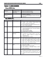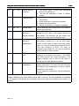
1
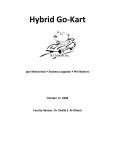
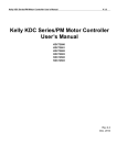
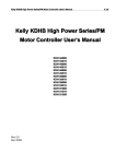
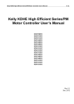
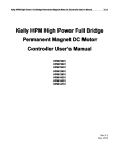
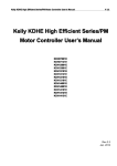
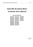
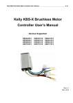
Kelly KBL Series Brushless Motor Controller User
User’’s Manual
V 2.0
Kelly KBL Series Brushless Motor
Controller User
User’’s Manual
Devices Supported:
24
101
KBL
KBL24
24101
2415
1
KBL
KBL2415
24151
24201
KBL
KBL24201
243
01
KBL
KBL243
24301
KBL48101
KBL48151
KBL48201
KBL48251
KBL48301
12151H
KBL
KBL12151H
3610
1
KBL
KBL3610
36101
36
151
KBL
KBL36
361
362
01
KBL
KBL362
36201
363
01
KBL
KBL363
36301
KBL72101
KBL72151
KBL72201
KBL72251
KBL72301
12221H
KBL
KBL12221H
Rev.2.0
Jan / 2008
Kelly KBL Series Brushless Motor Controller User
User’’s Manual
V 2.0
Contents
Chapter 1 Introduction.................................................2
1.1 Overview....................................................... 2
Chapter 2 Main Features and Specifications.............................3
2.1 General functions.............................................. 3
2.2 Features....................................................... 3
2.3 Specifications................................................. 4
2.4 Model.......................................................... 5
Chapter 3 Wiring and Installation......................................5
3.1 Mounting the Controller........................................ 5
3.2 Connections.................................................... 6
3.3 Installation Checklist........................................ 11
Chapter 4 Maintenance.................................................12
4.1 Cleaning...................................................... 12
4.2 Configuration................................................. 12
Table 1: LED CODES....................................................13
Contact Us:...........................................................15
Page 1
Kelly KBL Series Brushless Motor Controller User
User’’s Manual
V 2.0
Chapter 1 Introduction
1.1 Overview
The manual introduces Kelly BLDC motor controller features, installation and maintenance.
Read the manual carefully and thoroughly before use the controller. Should you have any
questions, please contact the support center of Kelly Controls, LLC.
Kelly’s programmable motor controllers provide efficient, smooth and quite controls for
electrical vehicles like golf cart, go-cart, electric motorcycle, fork lift, hybrid vehicle, as well as
electric boat and industry motor speed control. It uses high power MOSFET, fast PWM to
achieve efficiency >98% in most cases. Powerful microprocessor brings in comprehensive and
precise control to the controllers. It also allows users to set parameters, conduct tests, and
obtain diagnostic information quickly and easily.
Page 2
Kelly KBL Series Brushless Motor Controller User
User’’s Manual
V 2.0
Chapter 2 Main Features and Specifications
2.1 General functions
(1) Extended fault detection and protection. LED flashing for fault code.
(2) Monitoring battery voltage. Stop driving if battery voltage is too high or too low.
(3) Built-in current loop and over current protection.
(4) Controller temperature measurement and protection
(5) Current cutback at low temperature and high temperature to protect battery and controller.
The current will ramp down quickly if controller temperature is higher than 90C, and
shutdown at 100C. Low temperature current ramping down usually starts at 0C.
(6) The controller keeps monitoring voltage during regen. It will cut back current or stop regen if
voltage is too high.
(7) Configurable to limit max reverse speed to half of max forward speed
(8) Two RS232 ports. One for configuration, the other for application.
(9) Configurable and programmable with RS-232. Software upgradeable. Windows GUI
provided.
Provide 5V sensor supply
(10)
(11)Reverse alarm output. Recirculation diodes provided.
Motor temperature detection and protection
(12)
3 hall position sensor inputs. Open collector. The controller provides pull up.
(13)
3 switch inputs. Close to ground to activate. Default to throttle switch, brake switch and
(14)
reverse switch.
3 analog inputs, 0-5V. Default to throttle input, brake input and motor temperature input
(15)
Optional CAN bus.
(16)
Caution! Regeneration has braking effect, but can't replace mechanical brake. Mechanical
brake is required to stop your vehicle. Regen isn’t a safety feature! Controller may stop regen
to protect itself (not you!).
2.2 Features
•Intelligence with powerful microprocessor.
•Synchronos rectification, ultra low drop, fast PWM to achieve very high efficiency.
•Current limit and torque control.
•Low EMC.
•Battery protection: current cut back, shutdown and warning at low battery.
•Thermal enhanced rugged aluminum housing. Rugged connectors.
•Thermal protection: Current cut back on low temperature and high temperature to protect
battery and controller.
•Compatible with 60-degree or 120-degree hall position sensor.
•Support any number of poles.
•Up to 60000 electric RPM. (electric RPM = mechanical RPM * motor poles)
•High pedal protection: Disable operation if power up with non-zero throttle.
Page 3
Kelly KBL Series Brushless Motor Controller User
User’’s Manual
V 2.0
•Brake switch is used to start regen.
•0-5V brake signal is used to command regen current.
3 Specifications
2.
2.3
•Frequency of Operation: 16.6kHz.
•Standby Current: less than 3 mA.
•Supply Voltage, PWR, 18V to 90V.
•Supply Current, PWR, 150mA.
•Operating Voltage, B+, 18V to 1.25*Norminal.
•Analog Brake and Throttle Input: 0-5 Volts.
•Reverse alarm: <150mA.
•Full Power Operating Temperature Range: 0C to 50C (controller case temperature).
•Operating Temperature Range: -30C to 90C, 100C shutdown (controller case temperature).
•Armature Current Limit, 1 minute: 100A / 150A / 200A / 250A / 300A .
•Armature Current Limit, Continuous: 60A / 90A / 120A / 150A / 180A .
Page 4
Kelly KBL Series Brushless Motor Controller User
User’’s Manual
V 2.0
4 Model
2.
2.4
The naming regulation of the Kelly BLDC motor controller model:
KBL48101
The eighth letter represents whether the controller with
regeneration (0 represents non-regeneration, 1
represents with-regeneration).
The sixth and seventh letters represent the
max current divided by 10.
The fourth and fifth letters represent the
max voltage
The first three letters represent Kelly’s BLDC
motor controller.
Chapter 3 Wiring and Installation
3.1 Mounting the Controller
The controller can be oriented in any position as clean and dry as possible, or shield with a
cover to protect it from water and contaminants.
To ensure full rated output power, the controller should be fastened to a clean, flat metal
surface with four screws. Applying silicon gel or other thermal conductive material to contact
surface will enhance thermal performance.
Sufficient heat sink and airflow are required for high power application.
The case outline and mounting hole dimensions are shown in Figure 1.
Page 5
Kelly KBL Series Brushless Motor Controller User
User’’s Manual
V 2.0
Tall: 62 millimeters
Figure 1: mounting hole dimensions (dimensions in millimeters)
3.2 Connections
3.2.1 Front Panel of BLDC Motor Controller:
Five metal bars and two plugs (J1, J2) are provided for connections to the battery, motor
and control signals in the front of the controller shown as Figure 2.
Page 6
Kelly KBL Series Brushless Motor Controller User
User’’s Manual
Figure 2: Front panel of BLDC motor controller
B+: battery positive
B-: battery negative
A: Output U/1/A phase
B: Output V/2/B phase
C: Output W/3/C phase
Figure 3: The connecting diagram of J1 and J2
J1 Pin Definition
123456-
Red LED: Fault code
Reserved:
Reserved:
Alarm: To drive reverse beeper
GND: Signal return
Green LED: Running indication
7- GND: Signal return
er
8- RS232 receiv
receiver
er
9- RS232 transmitt
transmitter
10- CAN bus high
11- CAN bus low
12- Reserved
13- GND: Signal return, or power supply ground
ler power supply
14- PWR
PWR:: Control
Controller
J2 Pin Definition
Page 7
V 2.0
Kelly KBL Series Brushless Motor Controller User
User’’s Manual
V 2.0
ler power supply
1- PWR
PWR:: Control
Controller
2- GND: Signal return, or power supply ground
3- GND: Signal return
4- Motor temperature input.
5- Throttle analog input, 0-5V
6- Brake analog input
input,, 0-5V
7- 5V: 5V supply output
8- Throttle switch input
9- Reverse switch input
10- Brake switch input
11- Hall phase C
12- Hall phase B
13- Hall phase A
14- GND: Signal return
Notes:
1. All GND pins are internally connected. GND is internally connected to B2. Two PWR pins, J1-14 and J2-1, are internally connected. It
It’’s recommended to use
J1-14 to supply peripherals like alarm and meters. Twist peripheral wires with PWR
is the best for EMC. Recirculation diodes are provide in the controller for alarm and
meter drivers.
3. Switch to ground is active. Open switch is inactive
Caution: Make sure all connections are correct before apply power. Otherwise it may damage
the controller! Please securely wire B- before applying power. Never put contactor or break
on B-. Don't connect GND to B-.
Page 8
Kelly KBL Series Brushless Motor Controller User
User’’s Manual
3.2.2 Standard Wiring of BLDC Motor Controller
Figure 4: BLDC controller standard wiring
Page 9
V 2.0
Kelly KBL Series Brushless Motor Controller User
User’’s Manual
V 2.0
Figure 5: BLDC controller preferred wiring
Page 10
Kelly KBL Series Brushless Motor Controller User
User’’s Manual
Figure 6:
Page 11
The standard wiring of KBL12151H/KBL12221H
V 2.0
Kelly KBL Series Brushless Motor Controller User
User’’s Manual
V 2.0
3.2.
3 Communication Port
3.2.3
A RS232 port of controller is provided to communicate with host computer for calibration and
configuration.
Figure 6: standard RS232 interface
3.3 Installation Check list
Before operating the vehicle, complete the following checkout procedure. Use LED code as
a reference. The LED codes are listed in Table 1.
Caution:
• Put the vehicle up on blocks to get the drive wheels off the ground before beginning these
tests.
• Do not allow anyone to stand directly in front of or behind the vehicle during the checkout.
• Make sure the PWR switch and the brake is off
• Use well-insulated tools.
• Make sure the wire is connected correctly
• Turn the PWR switch on. The LED should blink, then keeps on when the controller
operates normally. If this does not happen, check continuity of the PWR and controller
ground.
• The fault code will be detected automatically at restart.
• With the brake switch open, select a direction and operate the throttle. The motor should
spin in the selected direction. Please verify wiring and voltage if it doesn’t. Also check fuse.
The motor should run faster with increasing throttle. If not, refer to Table 1 LED code, and
correct the fault according to the code.
• Take the vehicle off the blocks and drive it in a clear area. It should have smooth
acceleration and good top speed.
Page 12
Kelly KBL Series Brushless Motor Controller User
User’’s Manual
V 2.0
Chapter 4 Maintenance
There are no user-serviceable parts inside the controllers. Do not attempt to open the
controller. Or you will damage it. However, clearing the controller exterior periodically should be
necessary.
The controller is inherently a high power device. When working with any battery powered
vehicle, proper safety precautions should be taken. These include, but are not limited to: proper
training, wearing eye protection, avoiding loose clothing and jewelry, and using insulated
wrenches.
4.1 Cleaning
Although the controller requires virtually no maintenance after properly installation, the
following minor maintenance is recommended in certain applications.
• Remove power by disconnecting the battery.
• Discharge the capacitors in the controller by connecting a load (such as a contactor coil or
a horn) across the controller’s B+ and B- terminals.
•
Remove any dirt or corrosion from the bus bar area. The controller should be wiped with a
moist rag. Be sure it is dry before reconnecting the battery.
• Make sure the connections to the bus bars are tight. Use two wrenches for this task in order
to avoid stressing the bus bars; the wrenches should be well insulated.
4.2 Configuration
You can configure the controller with a host computer through RS232.
•
Use straight RS232 cable connecting the 9pin connector on face penal to a host computer
Provide 18V to 90V to PWR (either J2 pin1 or J1 pin14). Wire power supply ground to any
GND pin.
•
Do not connect B+, throttle and so on. The controller may display fault code, but it doesn't
affect programming or configuration.
Page 13
Kelly KBL Series Brushless Motor Controller User
User’’s Manual
V 2.0
Table 1: LED CODES
Green LED Codes
LED Code
Green Off
Green On
Green and Red LED
Keep On
Explanation
No power or not
operating
Normal operation
Solution
1. Check if all wires are correct.
2. Check fuse and power supply.
That’s great! You got solution!
1. Software is upgrading.
2. The controller is damaged. Please contact Kelly
for warrantee.
Red LED Codes
LED Code
1,2
¤
¤¤
Explanation
Over voltage error
1,3
¤
¤¤¤
Low voltage error
1,4
¤
¤¤¤¤
Over temperature
warning
2,1
¤¤
¤
Motor RPM over
low
2,2
¤¤
¤¤
Internal voltage
fault
2,3
¤¤
¤¤¤
Over temperature
Solution
1. Battery voltage is higher than max operating
voltage of the controller. Please check the
battery voltage and configuration.
2. Over voltage at regeneration. Controller will cut
back or stop regeneration.
1. The controller will attempt to clear the fault
code automatically after 5 second if battery
return to normal.
2. Check the battery voltage.
3. Charge battery if necessary.
1. The controller temperature is over 90ºC. The
controller will cut back current in the case.
Stop or reduce output to ensure the
temperature fall.
2. Improve heat sink or airflow
1. After 2 seconds which controller start to output,
motor rotate speed doesn't reach 25 electric
RPM, the controller will limit output current.
When motor rotate speed beyond 25 electric
RPM, output current won't be limited.
1. Check if the B+ and PWR voltage are correct,
refer to B- or GND.
2. Please check load on 5V supply.
3. The controller is damaged. Please contact
Kelly for warrantee.
1. The controller temperature is over 100ºC.
Controller stops driving in order to protect itself.
2. Stop driving and wait for temperature fall. The
controller will restart if temperature drops below
80ºC.
Page 14
Kelly KBL Series Brushless Motor Controller User
User’’s Manual
¤¤¤¤
Throttle error at
power up
2,4
¤¤
3,1
¤¤¤ ¤
Frequent reset
3,2
¤¤¤ ¤¤
Internal reset
3,4
¤¤¤ ¤¤¤¤
Throttle isn’t zero
when try to
change direction
4,1
¤¤¤¤ ¤
Over voltage at
startup or
regeneration
4, 2
¤¤¤¤ ¤¤
Hall sensor signal
error
4, 3
¤¤¤¤ ¤¤¤
Motor over
temperature
V 2.0
1. The throttle signal is higher than configured
dead zone at power-on
2. The fault will disappear if restart or release
throttle.
1. The controller will stop driving after detect too
many resets.
2. mostly because of overcurrent protection
3. Restart will clear the error.
4. Please contact Kelly if it happens repeatedly
Reset caused by over current or so. It is normal if
occurring occasionally.
The controller won’t change drive direction if
throttle isn’t zero. Also it won’t change direction at
high speed. The controller will wait throttle and
speed close to zero before change direction.
The controller won’t drive motor if detect
overvoltage at power up. It will cut back regen
current or stop regen if detect overvoltage during
regen. You may set overvoltage threshold with GUI.
The max threshold is about 1.25 times of
controller rated voltage. I.e. you may set threshold
lower than 60V for 48V controller.
120 degree hall motor produce the coding
belonging to 60 degree hall motor, or 60 degree
hall motor produce the coding belonging to 120
degree. Needing user to set the hall angle to
correct type through calibration software.
1.The motor temperature sensor beyond the
setting temperature, the motor will stop outputing
and waiting motor temperature to drop to original
temperature, then restart.
2.Can change the temperature through calibration
software.
The LED flashes once at power on, then keeps on for normal operation. “1, 2”
means it flashed once, then flashes twice after 1 second. The time between two flashes
is 0.5 second. The pause time between one error code and another error code is 2
second.
Page 15
Kelly KBL Series Brushless Motor Controller User
User’’s Manual
V 2.0
Contact Us:
Kelly Controls, LLC
Home Page:
http://www.KellyController.com
E-mail:
[email protected]
Phone:
(001) 224 637 5092
Page 16