1
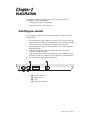
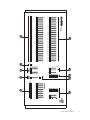
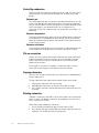
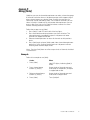
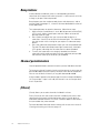
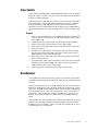
Lighting control system
Version 2.03
Table of Contents
Chapter 1
Introduction
Acclaim 100 features . . . . . . . . . . . . . . . . . . . . . . . . . . . . . . . . . . . .
Using this manual . . . . . . . . . . . . . . . . . . . . . . . . . . . . . . . . . . . . . .
Text conventions . . . . . . . . . . . . . . . . . . . . . . . . . . . . . . . . . . . . . . .
Pile-on convention . . . . . . . . . . . . . . . . . . . . . . . . . . . . . . . . . . . . . .
Customer service . . . . . . . . . . . . . . . . . . . . . . . . . . . . . . . . . . . . . .
1
2
2
2
3
Chapter 2
Installation
Installing your console . . . . . . . . . . . . . . . . . . . . . . . . . . . . . . . . . . . 5
Attaching dimmers . . . . . . . . . . . . . . . . . . . . . . . . . . . . . . . . . . . . . 6
Chapter 3
Learning the basics
Lesson 1: Acclaim 100 keyboard . . . . . . . . . . . . . . . . . . . . . . . . . . 8
Lesson 2: Creating and working with scenes and crossfades . . . 10
Manual crossfades . . . . . . . . . . . . . . . . . . . . . . . . . . . . . . . . . 10
Example . . . . . . . . . . . . . . . . . . . . . . . . . . . . . . . . . . . . . . . . . 11
Timed crossfades . . . . . . . . . . . . . . . . . . . . . . . . . . . . . . . . . . 12
To run timed crossfades, follow these steps: . . . . . . . . . . . . 12
Example . . . . . . . . . . . . . . . . . . . . . . . . . . . . . . . . . . . . . . . . . 13
Lesson 3: Creating and working with submasters . . . . . . . . . . . . 14
Creating and recording submasters . . . . . . . . . . . . . . . . . . . . 15
Example . . . . . . . . . . . . . . . . . . . . . . . . . . . . . . . . . . . . . . . . . 15
Controlling submasters . . . . . . . . . . . . . . . . . . . . . . . . . . . . . . 16
Pile-on convention . . . . . . . . . . . . . . . . . . . . . . . . . . . . . . . . . 16
Copying submasters . . . . . . . . . . . . . . . . . . . . . . . . . . . . . . . . 16
Deleting submasters . . . . . . . . . . . . . . . . . . . . . . . . . . . . . . . . 16
Lesson 4: Using [Solo] . . . . . . . . . . . . . . . . . . . . . . . . . . . . . . . . . 17
Example . . . . . . . . . . . . . . . . . . . . . . . . . . . . . . . . . . . . . . . . . 17
Lesson 5: Creating and working with chases . . . . . . . . . . . . . . . . 18
Creating a chase . . . . . . . . . . . . . . . . . . . . . . . . . . . . . . . . . . . 18
Example . . . . . . . . . . . . . . . . . . . . . . . . . . . . . . . . . . . . . . . . . 19
Viewing a chase . . . . . . . . . . . . . . . . . . . . . . . . . . . . . . . . . . . 19
Stopping a chase . . . . . . . . . . . . . . . . . . . . . . . . . . . . . . . . . . 19
Modifying chase rate and output level . . . . . . . . . . . . . . . . . . 20
Reversing a chase . . . . . . . . . . . . . . . . . . . . . . . . . . . . . . . . . . 20
Stepping through a chase . . . . . . . . . . . . . . . . . . . . . . . . . . . . 21
Deleting a chase . . . . . . . . . . . . . . . . . . . . . . . . . . . . . . . . . . . 21
Example . . . . . . . . . . . . . . . . . . . . . . . . . . . . . . . . . . . . . . . . . 21
Recording a chase while a chase is running . . . . . . . . . . . . . . 22
Blacking out chases . . . . . . . . . . . . . . . . . . . . . . . . . . . . . . . . 22
Chapter 4
Reference
Blackout . . . . . . . . . . . . . . . . . . . . . . . . . . . . . . . . . . . . . . . . . . . . .
Grandmaster [B/O] . . . . . . . . . . . . . . . . . . . . . . . . . . . . . . . . .
Chase [B/O] . . . . . . . . . . . . . . . . . . . . . . . . . . . . . . . . . . . . . . .
Bump buttons . . . . . . . . . . . . . . . . . . . . . . . . . . . . . . . . . . . . . . . .
Channel potentiometers . . . . . . . . . . . . . . . . . . . . . . . . . . . . . . . .
23
23
23
24
24
iii
[Chase] . . . . . . . . . . . . . . . . . . . . . . . . . . . . . . . . . . . . . . . . . . . . .
Cross faders . . . . . . . . . . . . . . . . . . . . . . . . . . . . . . . . . . . . . . . . .
Grandmaster . . . . . . . . . . . . . . . . . . . . . . . . . . . . . . . . . . . . . . . . .
Level potentiometer . . . . . . . . . . . . . . . . . . . . . . . . . . . . . . . . . . .
Power . . . . . . . . . . . . . . . . . . . . . . . . . . . . . . . . . . . . . . . . . . . . . .
Rate potentiometer . . . . . . . . . . . . . . . . . . . . . . . . . . . . . . . . . . . .
Reverse [Rev] . . . . . . . . . . . . . . . . . . . . . . . . . . . . . . . . . . . . . . . .
[Solo] . . . . . . . . . . . . . . . . . . . . . . . . . . . . . . . . . . . . . . . . . . . . . . .
[Step] . . . . . . . . . . . . . . . . . . . . . . . . . . . . . . . . . . . . . . . . . . . . . . .
[Stop] . . . . . . . . . . . . . . . . . . . . . . . . . . . . . . . . . . . . . . . . . . . . . . .
Submaster potentiometers . . . . . . . . . . . . . . . . . . . . . . . . . . . . . .
Submasters [Subs] . . . . . . . . . . . . . . . . . . . . . . . . . . . . . . . . . . . .
Time potentiometers . . . . . . . . . . . . . . . . . . . . . . . . . . . . . . . . . . .
[View] . . . . . . . . . . . . . . . . . . . . . . . . . . . . . . . . . . . . . . . . . . . . . .
24
25
25
26
26
26
27
27
27
27
28
28
29
29
Appendix A
Specifications
Output options . . . . . . . . . . . . . . . . . . . . . . . . . . . . . . . . . . . .
Controls . . . . . . . . . . . . . . . . . . . . . . . . . . . . . . . . . . . . . . . . .
Keyboard functions . . . . . . . . . . . . . . . . . . . . . . . . . . . . . . . . .
Size and weight . . . . . . . . . . . . . . . . . . . . . . . . . . . . . . . . . . .
Appendix B
Limited warranty
iv
Table of Contents
31
31
31
31
Chapter 1
Introduction
Welcome to Acclaim 100 from Electronic Theatre Controls. Acclaim 100
combines easy-to-use manual control with sophisticated electronic
features. The Acclaim 100 is available in four versions, each with a
different channel configuration:
• Model 112 with 12 control channels
• Model 124 with 24 control channels
• Model 136 with 36 control channels
• Model 148 with 48 control channels
This chapter orients you to the console and the manual. It includes the
following sections.
• Acclaim 100 features
• Using this manual
• Text conventions
• Pile-on convention
• Customer service
Acclaim 100 features
Acclaim 100 is a two-scene console that provides the following features:
• Independent faders that control manual and timed crossfades
• Eight manual faders that control programmed submasters
• 12, 24, 36, or 48 control channels (depending on model)
• Solo and bump buttons
• Programmable chase function
Acclaim 100 User Manual
1
Using this manual
This manual provides operating instructions for the Acclaim 100. The
following chapters are included:
Chapter 1 Introduction
Acclaim 100 capabilities, user manual conventions and customer support
information.
Chapter 2 Installation
Instructions for installing Acclaim 100
Chapter 3 Learning the basics
Tutorial on working with scenes, submasters and chases
Chapter 4 Reference
Description of console key functions and menu options in alphabetical
order.
Appendix A Specifications
Technical specifications for Acclaim 100
Appendix B Limited Warranty
Text conventions
In this manual, console buttons are indicated with square brackets, such
as [Chase]. Potentiometer settings are in bold type, such as 10.
References to other sections of the manual are printed in italics, as in
Chapter 1, Introduction.
Pile-on convention
Acclaim 100 uses a pile-on convention, rather than last-action convention,
to determine output levels for channels. This means that Acclaim 100
reads all output levels it receives for a specific channel and sets that
channel to the highest of these levels.
For example, assume a channel is included in a submaster and is also
included in an active scene. Acclaim 100 sets the channel at the greater
of the two settings.
2
Chapter 1 Introduction
Customer service
If you have problems with your system, please follow these steps:
1. Check the User Manual.
2. If you do not find the answer in the manual, call your local dealer or
ETC Technical Services. Please have the following information
available before you call:
•
System model and serial number (located on console’s back
panel)
•
Software version (displayed on Setup menu)
•
Dimmer installation type
•
Dimmer manufacturer
To reach Electronic Theatre Controls' US technical services department,
call Monday through Friday, from 8:00 AM to 6:00 PM Central Standard
Time. If calling from anywhere in the United States, place your call to
800-775-4382. From outside the United States, call the number listed
below under North America.
Address all correspondence about Acclaim 100 to:
North America
Electronic Theatre Controls, Inc.
Customer Service Department
3030 Laura Lane
Middleton, WI 53562
Phone: (+1) 608 831 4116
Europe:
Electronic Theatre Controls, Ltd
5 Victoria Industrial Estate
Victoria Road
London W3 6UU
Phone: (+44) 181 896 2000
Asia:
Electronic Theatre Controls
Room 605-606
Tower III, Enterprise Square
9 Sheung Yuet Road
Kowloon Bay, Hong Kong
Phone: (+852) 2799 9325
Internet
Email address: [email protected]
World Wide Web Home Page: www.etcconnect.com
Acclaim 100 User Manual
3
4
Chapter 1 Introduction
Chapter 2
Installation
This chapter includes installation instructions for the Acclaim 100
including the following procedures:
• Installing your Acclaim 100 console
• Connecting Acclaim 100 to dimmers
Installing your console
With reference to the back panel illustration below, install your Acclaim
100 as follows:
1. Place console on a hard, stable, flat surface with at least 6 inches of
space behind it for ventilation and cable clearance. Console should be
at least 6 feet away from dimmers and high-current AC lines.
2. Locate the power switch on the rear panel of the console and press
to the off position.
3. Insert the female end of the console power cord in the power
connector on the back panel.
4. Insert the male end of the console power cord in a grounded 120 VAC
AC outlet. For 220 VAC operation, consult Electronic Theatre Controls.
5. Press the power switch the the on position.
➍
➌
PUSH
CAUTION
DO NOT REMOVE COVER
REFER SERVICING TO QUALIFIED
SERVICE PERSONNEL
➊ ➋
➊
➋
➌
➍
Power Connector
Power Switch
Fuse
DMX512 Connector
Acclaim 100 User Manual
5
Attaching dimmers
The Acclaim 100 provides USITT standard, DMX512 output through a fivepin connector located on the console’s back panel. This dimmer output
port can control 12, 24, 36, or 48 dimmers, depending on the Acclaim
model you purchase.
Connector
XLR 5 pin female
Pinout
1
2
3
4
5
6
Chapter 2 Installation
Common
Data (-)
Data (+)
No connection
No connection
Chapter 3
Learning the basics
This chapter includes lessons on Acclaim 100's features: scenes,
submasters and chases. Each lesson is described briefly below.
• Lesson 1 describes the Acclaim 100 keyboard.
• Lesson 2 describes how to create scenes and run manual and timed
crossfades.
• Lesson 3 includes instructions for creating and using submasters.
• Lesson 4 describes bump buttons, [Solo] and [B/O] (black out)
buttons, and the Grand Master.
• Lesson 5 includes instructions for creating and working with chase
routines.
For an alphabetical listing and detailed explanation of each feature, see
Chapter 4, Reference.
Acclaim 100 User Manual
7
Lesson 1:
Acclaim 100 keyboard
This lesson familiarizes you with the Acclaim 100 keyboard, shown on the
next page.
➊ Channel potentiometers
Channel pots set individual channels' output levels. For more information
see page 24.
➋ Time potentiometers
Time pots control the speed at which a timed crossfade takes place. For
more information see page 29.
➌ Mode
Three mode buttons allow you to record and view chases and record
submasters. NOTE: The top Mode button is not used. Labels pertain to
the buttons below. For more information see pages 24, 28 and 29.
➍ [B/O]
The [B/O] (black out) key forces all channels to a zero intensity level. For
more information see page 23.
➎ Chase
Chase buttons and pots allow you to control the rate and intensity of
chases. For more information see pages 23 and 27.
➏ Channel bump buttons
Channel bump buttons momentarily raise channel outputs to full intensity
levels. For more information see page 24.
➐ Solo
[Solo] enables you to use channel bump buttons to force selected
channels to full intensity and suppress unselected channels' outputs to
zero. For more information see page 27.
➑ Cross faders
Cross faders allow you to control crossfades. A row of LEDs next to each
cross fader allows you to visually track the progress of fades. For more
information see page 25.
➒ Grandmaster
Grandmaster controls intensity levels of all channels and submasters. For
more information see page 25.
➓ Submasters
Submaster pots and bump buttons allow you to control submasters'
intensity levels. For more information see pages 24 and 27.
8
Chapter 3 Learning the basics
➊
➏
➒
➋ ➌➍
➐ ➑
➓
➎
Acclaim 100 User Manual
9
Lesson 2:
Creating and working with scenes and crossfades
A scene is a group of channels set at specific levels to create a look on
stage. The Acclaim 100 console has two rows of control channel
potentiometers that allow you to create two different scenes -- scene A
and scene B. Channel potentiometers, or pots, allow you to individually
control the output for each channel.
Acclaim 100's A and B cross faders control the output for scenes A and B
respectively. These two cross faders function independently one controls
the output of scene A, the other controls scene B. Each cross fader has a
strip of LEDs next to it that indicates the progress of the cross fade. In a
manual cross fade the LEDs follow the movement of the cross faders; in
a timed cross fade, they indicate the percentage of playback time that has
run. (See Timed crossfades, page 12, for an explanation of the role of the
cross faders in timed crossfades.)
Note: You may find it helpful to refer to the fold-out keyboard illustration
in Appendix B while you read this section. This fold-out illustration lets you
to refer to the keyboard while you read the manual.
If you have created looks in both scene A and scene B, you can use two
cross faders to bring one scene up while fading the other scene out. This
is called a crossfade.
Manual crossfades
In a crossfade, you normally set the channel settings for one scene while
another is live on stage. When you want to change from one scene to
another, you can simultaneously fade the live scene out and bring the next
one up, using the cross faders.
Follow these steps to create scenes and run manual crossfades:
1. Make sure the Grand Master is set at 10 (100 percent), the [B/O] LED
is not lit, and the Time pots are set at 0. Then set both scene A and B
cross faders at 0.
2. Create scene A by setting scene A channel pots to desired levels.
3. Bring up scene A by moving scene A cross fader to 10.
4. With scene B cross fader at 0, set scene B channel pots at desired
levels for scene B.
5. Pull both cross faders down simultaneously to start the crossfade,
bringing scene B up and fading scene A out. Move scene A cross
fader to 0 and scene B cross fader to 10.
6. With scene A cross fader at 0, set scene A channel pots at desired
levels for next scene A.
7. Push both cross faders up simultaneously to start the next crossfade,
bringing scene A up and fading scene B out. Move scene B cross
fader to 0 and scene A cross fader to 10.
8. Repeat steps four through seven for each scene change.
Note: Scene A is at full intensity when the cross fader handle is at the top
of the pot scene B is at full intensity when its cross fader handle is at the
bottom of the pot. This allows you to easily execute smooth cross fades
by moving both cross faders simultaneously with one hand.
10
Chapter 3 Learning the basics
Example
Follow this example to create scenes A and B and run a manual crossfade
between the two scenes. Before you start, make sure Grandmaster is set
at 10 and [B/O] LED is not lit.
Action
Effect
1. Move scene A and B cross
faders to 0.
Sets output of all channels at zero
percent.
2. Set Time pot at 0.
Sets fade time at zero (fade is
manually controlled by moving
cross faders).
3. Move scene A pots 1
through 5 to 7; set
remaining scene A pots at 0.
Sets scene A channels 1 through 5
at 70 percent; all other channels are
set at zero percent.
4. Move scene A cross fader to
10.
Brings up scene A.
5. Move scene B pots 6
through 10 to 4; set
remaining channels at 0.
Sets scene B channels 6 through 10
at 40 percent; sets all other
channels at zero percent.
6. Move scene A cross fader to
0 and scene B cross fader to
10 simultaneously.
Fades scene A out and brings scene
B up on stage.
7. Move scene A cross fader to
10 and scene B cross fader
to 0 simultaneously.
Fades scene B out and brings scene
A up on stage.
Acclaim 100 User Manual
11
Timed crossfades
Sometimes you may prefer to change scenes using timed crossfades.
Because they are not controlled by physical movement of the cross
faders, timed crossfades are generally smoother than manual fades,
especially when the fade takes place over a relatively long time. The
primary difference between manual and timed cross fades is the role of
the cross faders.
In manual crossfades, the speed at which you move the cross faders
determines the fade rate. In a timed crossfade, you vary the fade rate by
changing the position of the Time pots. For example, set the scene A Time
pot at 1m (one minute), then move the scene A cross fader from 10 (100
percent) to 0 (zero percent). Scene A fades out in one minute.
In a timed crossfade, the cross faders control the extent of a fade, but the
Time pot controls how long it will take. However, if you move the scene
A cross fader to 5, scene A output will fade to only 50 percent over a
period of 30 seconds. The fade rate stays the same because the Time pot
setting is not changed, but the fade will not complete if the cross fader is
not set to 10.
Each cross fader has its own Time pot, which gives you independent
control of the rate at which the two scenes fade. For example, scene A
might come up in 30 seconds, while scene B takes two minutes to fade
out. The Time pots are marked from 0 to 5m, indicating fade durations of
from zero to five minutes. When you set Time pots at 0, you must
manually fade the scenes in and out with the cross faders.
Each fader has a strip of LEDs next to it. As a fade runs, the LEDs light in
sequence, tracking the progress of the fade. When you run a manual fade
the LEDs light as you move the fader. When running a timed cross fade,
the LEDs light, and the fade progresses, according to the fade rate
determined by the position of the Rate pot.
To run timed crossfades, follow these steps:
1. Make sure the Grand Master is set at 10 (100 percent), the [B/O] LED
is not lit, and the Time pots are set at 0. Then set both scene A and B
cross faders at 0.
2. Create scene A by setting scene A channel pots at desired levels.
3. Bring up scene A by moving scene A pot to 10.
4. With scene B cross fader at 0, set scene B channel pots at desired
levels for scene B.
5. Set scene A and B Time pots to desired fade time settings.
6. Pull both cross faders down simultaneously to start the timed
crossfade. The crossfade starts as soon as you move the cross faders
and continues at the programmed rate. The progress of the fade can
be tracked by the LEDs to the left and right of the cross faders.
7. You can stop the fade in progress by moving the cross faders back to
meet the lit LEDs.
8. To restart the fade, move both cross faders again in the original
direction. The fade resumes.
9. You can reverse the direction of the fade by moving the cross faders
back toward their starting point.
12
Chapter 3 Learning the basics
Example
Follow this example to create scenes A and B and run a timed crossfade
between the two scenes. Before you start, make sure Grandmaster is set
at 10 and [B/O] LED is off.
Action
Effect
1. Move scene A and B cross
faders to 0.
Sets output of all channels at zero
percent.
2. Set Time pot at 0.
Sets fade time at zero (fade is
manually controlled by moving
cross faders).
3. Move scene A pots 1
through 5 to 7; set
remaining scene A pots at 0.
Sets scene A channels 1 through 5
at 70 percent; all other channels are
set at zero percent.
4. Move scene A cross fader to
10.
Sets output of all scene A channels
at 100 percent.
5. Set scene A and B Time pots
at 1m.
Sets scene A and B fade times at
one minute.
6. Move scene B pots 6
through 10 to 4; set
remaining channels at 0.
Sets scene B channels 6 through 10
at 40 percent; sets all other
channels at zero percent.
7. Move scene A cross fader to
0 and scene B cross fader to
10 simultaneously.
Fades scene A out and brings scene
B up on stage. Crossfade takes one
minute.
Acclaim 100 User Manual
13
Lesson 3:
Creating and working with submasters
A submaster is a group of channels recorded at specific levels in a
submaster potentiometer. The Acclaim 100 console is equipped with
eight submaster potentiometers, or pots. Each submaster pot allows you
to proportionally control the output of the channels in a submaster.
Submasters enable you to save looks that you use often and to access
them easily. You can use submasters as building blocks when you create
scenes or other submasters. For example, you might create a different
submaster for each cyclorama wash another submaster might include a
practical. Or, you might choose to create a series of submasters for each
area of your set.
A submaster bump button is located below each submaster pot. The
submaster bump button allows immediate output of a submaster to its full
recorded intensity for as long as you press the button.
When a submaster pot is set at 0, the channels that make up the
submaster are set at zero percent of their recorded output level. To
increase the output level, push the submaster pot up. When the pot is set
at 10, the submaster's channels are at 100 percent of their recorded
output level. You can set the level of output intensity at any point between
0 and 10.
This lesson includes the following sections:
• Creating and recording submasters
• Controlling submasters
• Copying submasters
• Deleting submasters
14
Chapter 3 Learning the basics
Creating and recording submasters
Creating a submaster involves setting channel levels to create a scene
then recording those settings in a submaster pot. All channels that are live
on stage when the submaster is recorded become part of the submaster.
Be sure that only the channels you want to be part of the submaster are
on stage when you record the look.
A channel can be included in as many submasters as you choose. To
record a submaster, follow these steps:
1. Make sure the Grandmaster is set at 10 (100 percent) and the [B/O]
LED is not lit. Adjust channel pots and cross faders to create the
desired scene on stage.
2. Press [Subs] to indicate that you want to record the look as a
submaster. A red LED to the left of the button lights. This indicates
that the Acclaim 100 is waiting for you to press a submaster bump
button.
3. Press the submaster bump button where you want to record the look.
The red LED above the bump button lights momentarily, then both
LEDs go out, indicating that the submaster has been recorded.
4. To verify that submaster was correctly recorded, set all other
submaster and channel pots to 0. Push the submaster pot up to 10
the channels come up at the levels you recorded.
Example
Follow this example to record a submaster. Before you start, make sure
Grandmaster is set at 10 and [B/O] LED is not lit.
Action
Effect
1. Set cross fader A at 10 and
cross fader B at 0.
Sets scene A outputs at 100 percent
and scene B at zero.
2. Move scene A channel
pots 1-10 to 10.
Sets channel output levels on stage
at 100 percent.
3. Press [Subs].
Prepares console to record channels
as submaster; [Subs] LED lights.
4. Press submaster bump
button under pot
number 3.
Records channels 1 through 10 at 100
percent in submaster number 3
Acclaim 100 User Manual
15
Controlling submasters
There are three ways to bring a submaster up on stage. You can use the
submaster pot, the submaster bump button, or the submaster [Solo]
button.
Submaster pot
To use the submaster pot, set the pot at the desired output level. As you
move it from 0 to 10, the output level increases from zero to 100 percent.
You can set the intensity level of the outputs at any point between 0 and
100. For example, if you record channels set at 100 percent in a
submaster, and set the submaster pot at 5 (50 percent), the output is at
50 percent.
Submaster bump button
The submaster bump button allows you to immediately bring a submaster
to 100 percent of its recorded level for as long as you press the button.
When you release the bump button, the channels in the submaster revert
to their previous levels.
Submaster solo button
The submaster [Solo] button has the same effect as the bump button, but
it also suppresses the output levels of all other submasters to zero.
Pile-on convention
Acclaim 100 uses a pile-on convention, rather than last-action convention,
to determine output levels for channels. Acclaim 100 reads all output
levels it receives for a specific channel and sets that channel to the
highest of these levels.
For example, if a channel is included in a submaster and in an active
scene, the channel outputs at the higher of the two settings.
Copying submasters
You may want to copy a submaster or use submasters as building blocks
for new submasters.
To copy a look from one submaster to another, follow these steps:
1. Bring up the submaster you want to copy.
2. Add additional submasters or channels to the look on stage.
3. Press [Subs], then press the bump button of the submaster you want
to record.
Deleting submasters
To delete a submaster, rerecord it with all channel pots set at zero output
levels. In effect, you delete a submaster by recording a new one over it
with all channels set at zero.
Follow these steps to delete a submaster:
1. Set all channel and submaster pots to zero, or press [B/O].
2. Press [Subs], then press the bump button for the submaster you want
to delete. This records all levels at zero percent.
16
Chapter 3 Learning the basics
Lesson 4:
Using [Solo]
[Solo] lets you use the channel bump buttons to select a channel or group
of channels and raise them to 100 percent output while suppressing all
other channel outputs to a level of zero. Channels that are part of a
submaster are not affected by [Solo]. The number of channels you can
select in [Solo] is limited only by the number of bump buttons you can
press at one time. You can use [Solo] to isolate a subset of a scene
without affecting the other channels.
Follow these steps to use [Solo]:
1. Press [Solo]. A red LED to the left of the key lights.
2. Press and hold channel bump buttons you want to isolate. The
selected channels immediately output at 100 percent all other
channels are suppressed to zero.
3. Release the bump buttons to return all channels to their previous
levels.
4. Press [Solo] again to leave [Solo] mode. Now channel bump buttons
perform as usual, flashing channel levels to 100 percent without
affecting other channel output levels.
Note: Pressing [Solo] does not affect output levels of channels included
in submasters.
Example
Follow this example to use [Solo]:
Action
Effect
1. Press [Solo].
Solo] LED lights, indicating [Solo] is
effect.
2. Press channel bump
buttons [1] and [3].
Output levels of channels one and
three jump to 100 percent; all output
is suppressed to zero.
3. Release channel bump
buttons [1] and [3].
Output levels of channels one and
three revert to original level.
4. Press [Solo].
Turns [Solo] off.
Acclaim 100 User Manual
17
Lesson 5:
Creating and working with chases
A chase is an effect in which a group of channels are flashed to full
intensity one at a time, and in a predetermined sequence. The sequence
continues to run until it is disabled on the console. You can use the chase
feature to create marquee or runway effects. You can adjust channel and
submaster output levels while a chase is running without affecting the
chase.
This lesson includes the following sections:
• Creating chases
• Viewing chases
• Stopping chases
• Modifying chase rate and intensity levels
• Reversing chases
• Stepping through chases
• Deleting chases
• Recording a new chase while a chase is running
• Blacking out chases
Creating a chase
To create a chase sequence follow these steps:
1. Press [Chase] the red LED indicates that a chase is being recorded.
2. Press the bump buttons for the channels that you want to include in
the chase. As you press each bump button, a red LED lights above the
bump button, indicating that that channel has been included in the
chase.
Note: Channels appear in chase in the sequence in which you enter them.
3. Press [Chase] again to initiate the chase. The red LED to the left of the
[Chase] key goes out. The chase is now entered and running on stage.
See Viewing a chase, page 19, to learn how to monitor the chase
using the channel LEDs.
Note: The chase continues to run until it is stopped or deleted. For
directions on how to stop a chase see page 19. For directions on how to
delete a chase see page 21.
18
Chapter 3 Learning the basics
Example
Follow this example to create a chase:
Action
Effect
1. Press [Chase].
[Chase] LED lights, indicating that a
chase is being created.
2. Press channel bump
buttons [1], [2] and [3].
Enters channels 1, 2 and 3 in chase.
3. Press [Chase].
Records channels 1, 2 and 3 in chase
and starts chase running.
Viewing a chase
You may find it easier to work with chases if you can see them on the
console. Acclaim 100's [View] function enables you to monitor the
progress of a chase by watching a sequence of channel LEDs on the
console keyboard. To view a chase follow these steps:
1. Press [View] to see the chase's channel LEDs light in sequence as the
chase runs.
2. Press [View] again to turn off the [View] function.
Stopping a chase
[Stop] enables you to stop and restart a chase. When you stop a chase,
the chase stops immediately. The channel that is live when you press
[Stop] remains on stage until you press [Stop] again, restarting the chase.
1. Press [Stop] to stop the chase.
2. Press [Stop] again to restart it. The chase restarts from the channel on
which it stopped.
Acclaim 100 User Manual
19
Modifying chase rate and output level
While a chase is running, you can modify its speed and intensity using the
Rate and Level pots.
Using the Level pot
When you record a chase with Acclaim 100, all channels are automatically
entered at full intensity regardless of the channel pot setting. To modify
the output level of chase channels you must use the Level pot.
The Level pot sets all channels included in the chase at the same level
from zero to 100 percent. Setting the pot at 0 blacks out the chase. Chase
output can be set at any point from 0 to 10.
The numbers next to the pot indicate the chase's output level. The scale
is marked 0 through 10, representing the percentage of output divided by
10. For example, if the pot is set at 5, the output levels of the channels in
the chase are set at 50 percent.
Using the Rate pot
The Rate pot controls the speed at which a chase proceeds by varying the
length of time each channel remains on stage before the next channel
comes up. To change the speed of a chase, move the Rate pot up or
down.
As you move the pot from 1s to .1s, the rate of the chase decreases from
one second per channel to a tenth of a second per channel. For example,
if a pot is set at .5s, each channel in the chase flashes for one half second
before the next one flashes.
Reversing a chase
The channels that make up a chase flash in the sequence in which you
recorded them. [Rev] reverses the sequence in which they flash.
To reverse a chase, follow these instructions:
1. Press [Rev]. A red LED indicates that the chase direction has been
reversed. If the console is in the [View] mode, the channel LEDs
reverse direction.
2. To return to the original chase direction, press [Rev] again. The red
LED goes out. If the console is in the View mode, the channel LEDs
also revert back to their original direction.
20
Chapter 3 Learning the basics
Stepping through a chase
Press [Step] to proceed through a chase one channel at a time. If you do
not stop the chase before pressing [Step], the chase immediately
advances to the next chase channel, then continues at the programmed
rate.
To step through a chase, follow these steps:
1. Press [Stop] to stop the chase.
2. Press [Step] to flash the next channel in the sequence.
3. Press [Step] to flash the next channel in the sequence, and again for
each subsequent channel.
4. Press [Stop] again to leave [Step] and restart the chase.
Note: To reverse the direction in the [Step] mode, press [Rev] and
continue pressing [Step] for each subsequent channel in the new
direction.
Deleting a chase
To delete a chase you must record a new one that contains no channels.
To record a chase with no channels, follow these steps:
1. Press [Chase] the red LED immediately to the left of [Chase], and the
LEDs corresponding to each channel in the chase light.
2. Press the channel bump button over each illuminated LED. As you
press each bump button, the LED above it goes out, indicating that
that channel has been deleted.
3. Press [Chase] again when all the channels have been deleted. In
effect, this records a new chase that contains no channels.
Example
Follow this example to delete the chase you created in Creating a chase,
page 18:
Action
Effect
1. Press [Chase].
[Chase] LED and channel LEDs for
channels 1, 2 and 3 light.
2. Press channel bump
buttons [1], [2] and [3].
Channel LEDs go out, indicating that
corresponding channels have been
deleted from chase.
3. Press [Chase].
[Chase] LED goes out, chase is
recorded with no channels (channels
set to zero).
Acclaim 100 User Manual
21
Recording a chase while a chase is running
You can record a new chase while an active chase is running without
affecting the active chase. The procedure is the same as described
previously. The existing chase continues to run until you press [Chase] to
record the new channel sequence, at which point the new chase starts.
Blacking out chases
Pressing Chase [B/O] (black out) button blacks out a chase without
affecting other outputs. The chase continues to run on the console. This
can be helpful if you want to stop the chase briefly, then bring it back up
without deleting and recreating it manually.
To black out a chase follow these steps:
1. Press Chase [B/O]. A red LED lights indicating that a chase is running
but is not live on stage.
2. Press [B/O] again to bring the chase back up on stage.
Note: When you turn the console on, Chase B/O is in effect. Press Chase
[B/O] to turn off the [B/O].
22
Chapter 3 Learning the basics
Chapter 4
Reference
This reference chapter lists all Acclaim 100 buttons and features in
alphabetical order. Listings include a description of the feature and
instructions for using it.
Blackout
Acclaim 100 has two [B/O] (black out) buttons. The Grandmaster [B/O]
blacks out all console output. The Chase [B/O] blacks out only a running
chase.
Grandmaster [B/O]
The Grandmaster [B/O] blacks out all channel output levels. It is located
above the Grandmaster pot.
Example
1. Press [B/O] to force all channels to a zero intensity level. A red LED
lights when console is in black out mode.
2. Press [B/O] again to restore channel levels. The LED goes out
indicating that console output is no longer blacked out.
Chase [B/O]
The Chase [B/O] key is located to the left of the chase Level and Rate
pots. It blacks out a chase on stage, but allows it to continue running on
the console. This can be helpful if you want to stop the chase briefly, then
bring it back up on stage without deleting and recreating it.
Example
1. Press [B/O] to black out the chase on stage.
2. Press [B/O] again to bring the chase back up on stage.
Note: If you have activated [View], the channel LEDs will continue to
display the chase even though it does not appear on stage. See page 29
to learn more about [View].
Acclaim 100 User Manual
23
Bump buttons
A bump button immediately raises its corresponding channel or
submaster to full output level when you press it. Levels remain at full for
as long as you press the bump button.
Bump buttons are also used to record chases and submasters, and to
activate [Solo]. See pages 15, 18 and 27 for more detailed discussions of
these applications.
To use bump buttons to record a submaster, follow these steps:
1. Make sure the Grand Master is set at 10 (100 percent) and the [B/O]
LED is not lit. Adjust channel pots and cross faders to create the
desired scene on stage.
2. Press [Subs] to indicate that you want to record the look as a
submaster. A red LED to the left of the button lights. This indicates
that the Acclaim 100 is waiting for you to press a submaster bump
button.
3. Press the submaster bump button where you want to record the look.
The red LED above the bump button lights momentarily, then both
LEDs go out, indicating that the submaster has been recorded.
4. To verify that submaster was correctly recorded, set all other
submaster and channel pots to 0. Push the submaster pot up to 10
the channels come up at the levels you recorded.
Channel potentiometers
Channel potentiometers control the intensity level of individual channels.
To increase a channel's intensity level, push the pot up. As you move the
pot from 0 to 10, the level of intensity increases from zero to 100 percent.
You can set the level of intensity at any point between 0 and 10.
Scale numbers represent the percentage of maximum output divided by
10. For example, if a pot is set at 5, the channel is set at an output level
that is 50 percent.
[Chase]
[Chase] allows you to select channels included in a chase.
Press [Chase] to view the current channels included in the chase. After
selecting chase channels with bump buttons, press [Chase] again to
record the selected channels as a chase. Channels appear in the chase in
the same order they were entered.
For more detailed information about working with chases see Lesson 5:
Creating and working with chases, page 18.
24
Chapter 4 Reference
Cross faders
Cross faders are independently operated potentiometers that set output
levels for scenes A and B. You can use the cross faders to control either
manual or timed crossfades.
To bring up scene A and fade out scene B at the same time, push faders
up simultaneously. Pulling faders down together reverses this process,
bringing scene B up and fading out scene A. Because faders move
separately, you can change output levels of both scenes independently.
For more information on timed crossfades, see Timed crossfades, page
12.
Example
1. Make sure the Grandmaster is set at 10 (100 percent), the [B/O] LED
is not lit, and the Time pots are set at 0. Then set both scene A and B
cross faders at 0.
2. Create scene A by setting scene A channel pots to desired levels.
3. Bring up scene A by moving scene A cross fader to 10.
4. With scene B cross fader at 0, set scene B channel pots at desired
levels for scene B.
5. Pull both cross faders down simultaneously to start the crossfade,
bringing scene B up and fading scene A out. Move scene A cross
fader to 0 and scene B cross fader to 10.
6. With scene A cross fader at 0, set scene A channel pots at desired
levels for next scene A.
7. Push both cross faders up simultaneously to start the next crossfade,
bringing scene A up and fading scene B out. Move scene B cross
fader to 0 and scene A cross fader to 10.
8. Repeat steps four through seven for each scene change.
Grandmaster
The Grandmaster controls the intensity level of all Acclaim 100 channels.
It overrides all other controls except [B/O]. See page for more information
on [B/O].
Normally the Grandmaster is set at 10 (100 percent) so that all channels
operate at 100 percent of their set levels. When the Grandmaster is set at
a level less than 10, channel outputs equal current settings multiplied by
the percentage level at which the Grandmaster is set. For example, if a
submaster is set at 50 percent, and the Grandmaster is also set at 50
percent, the channels output at 25 percent of their recorded intensity
levels.
The numbers next to the Grandmaster indicate the output level at which
the pot is set. Numbers represent the percentage of maximum output
divided by 10. For example, if a pot is set at 5, the Grandmaster is set at
an output level that is 50 percent.
Acclaim 100 User Manual
25
Level potentiometer
The Level potentiometer controls output levels of channels in a chase. If
a channel is included in both a scene and a chase, the Level pot setting
affects its output only when it is flashed as part of a chase sequence.
When channels are recorded in a chase, they are automatically recorded
at full intensity. Changing the Level pot setting changes the intensity of all
channels in the chase equally.
To change the output level of a chase, move the pot up or down. As you
move the pot from 10 to 0, the level of output intensity decreases from
100 percent to zero. Setting the Level pot at 0 has the same effect as
pressing chase [B/O]. See page 23 for more information on [B/O].
The numbers next to the pot indicate the output level of the chase. The
scale is marked 0 through 10, representing the percentage of maximum
output divided by 10. For example, if the pot is set at 5, the output levels
of the channels in the chase are set at 50 percent.
Example
Record a chase including channels 1 through 10, all channels are
automatically recorded at full intensity. While chase is running, move
Level pot to 4. Each channel flashes at 40 percent of maximum output
level.
Power
Acclaim 100's power switch is located on the rear panel of the console.
Electronic Theatre Controls recommends that you turn the console power
switch to the OFF position before you plug or unplug the power cable.
Rate potentiometer
The Rate pot controls the speed at which a chase proceeds by varying the
length of time each channel in the chase flashes before the next channel
comes up.
To change chase rate, move the Rate pot up or down. The numbers next
to the pot indicate the speed of the chase in seconds. As you move the
pot from 1s to .1s, the rate of the chase decreases from one second per
channel to a tenth of a second per channel.
Example
Record a chase including channels 1 through 10. Set the Rate pot at 1s to
flash each channel in the chase for one second. To speed up the chase,
pull the Rate pot down to .5s each channel flashes for one half a second.
26
Chapter 4 Reference
Reverse [Rev]
[Rev] lets you reverse the direction of a chase in progress; it does not stop
the chase. You do not need to stop the chase before you press [Rev] in
order to reverse its direction.
Example
A chase running through channels 1 through 5 consecutively runs
channels 5 through 1 after you press [Rev].
[Solo]
[Solo] lets you use the channel bump buttons to select a channel or group
of channels and suppress all others to a level of zero. [Solo] is useful for
isolating a subset of a scene to readjust or refocus fixtures without
affecting other channels.
[Step]
[Step] allows you to flash one channel at a time in a running chase. Each
time you press [Step], the next channel in the chase sequence flashes to
full.
1. Press [Stop] to stop a running chase.
Note: If you do not stop the chase before pressing [Step], the chase
immediately advances to the next chase channel, then continues at the
programmed rate.
2. Press [Step] to flash the next channel in the sequence.
3. Press [Step] to flash the next channel in the sequence, and again for
each subsequent channel.
To reverse the direction of the chase while in [Step]:
1. Press [Rev].
2. Press [Step] to continue in the new direction.
3. Press [Rev] again to return to the original chase direction.
4. Press [Stop] again to leave [Step] and restart the chase.
[Stop]
[Stop] allows you to stop and restart a chase. Whichever chase channel is
live when you press [Stop] remains live until you restart the chase by
pressing [Stop] again. [Stop] does not erase a recorded chase, nor does it
black out the chase.
1. Press [Stop] once to stop a running chase.
2. Press [Stop] again to resume the chase.
Acclaim 100 User Manual
27
Submaster potentiometers
Acclaim 100 has eight submaster potentiometers, or pots. You can record
a submaster in each pot.
To record a submaster in a submaster pot, follow these steps:
1. Adjust channel pots to create the desired scene on stage.
2. Press [Subs] to indicate that you want to record the look as a
submaster. A red LED to the left of the key lights. This indicates that
the Acclaim 100 is waiting for you to press a submaster bump button.
3. Press the submaster bump button where you want to record the look.
4. Set all channel pots at zero, then push the submaster pot up to 10.
The channels you recorded come up at the proportionate levels you
recorded.
For more information on submasters, see pages 15 through 16.
To bring a submaster up, push pot up. As you move pot from 0 to 10, the
level of intensity increases from zero to 100 percent.
The numbers next to the submaster pots indicate the output level at
which the submasters are set. They represent the percentage of output
divided by 10. For example, if a pot is set at 5, the submaster is set at an
output level that is 50 percent of its recorded output.
Submasters [Subs]
Pressing [Subs] indicates you will press a submaster bump button to
record a sub.
After you have used channel and submaster pots to create the look you
want, press [Subs] and then one of the submaster bump buttons. This
records the look as a submaster. The submaster is stored in the pot
immediately above the bump button.
28
Chapter 4 Reference
Time potentiometers
The two Time pots control the duration of crossfades. Each one controls
the fade time of the cross fader immediately below it on the console. They
can be set separately to program different fade rates for each scene.
The numbers 0 to 5m between the two pots indicate fade durations of
from zero to five minutes. If you set the Time pot at 5m, the fade takes
five minutes. At 1m, the fade takes one minute. At 0 there is no
programmed fade time you must control the fade manually.
To change the speed of a crossfade, move the Time pots up or down.
Pulling the pots down decreases the fade rate. Pushing the pots up
increases the fade rate. You can set the rate of the fade at any point
between 0 and 5m.
Once the fade time for a scene is set, initiate the cross fade by moving
the cross fader for that scene.
Example
Set the scene A Time pot at 1m (one minute), then move the scene A
cross fader from 10 (100 percent) to 0 (zero percent). All scene A output
fades out in one minute.
In a timed crossfade, the cross faders control the extent of a fade, but the
Time pot controls how long it will take. If you move the scene A cross
fader to 5, then move the scene A cross fader from 10 (100 percent) to 0
(zero percent), scene A output fades to 50 percent over a period of 30
seconds. The fade rate stays the same because the Time pot setting is not
changed.
[View]
[View] allows you to observe the progress of a chase as it runs. Channel
LEDs flash as channels flash on stage
Example
Press [View], channel LEDs included in the chase flash as channels flash
on stage. Press [View] again to turn the function off.
Acclaim 100 User Manual
29
30
Chapter 4 Reference
Appendix A:
Specifications
Output options
•
DMX512 digital output through 12, 24, 36, or 48 control channels,
depending on model
Controls
•
•
•
•
•
Manual and timed crossfades
Channel potentiometers
• Two rows of 12, 24, 36, or 48 each depending on model
• Bump/Solo buttons on all channel potentiometers
Eight submaster potentiometers
• Fully overlapping channel assignments
• Proportional channel levels
• Bump and [Solo] buttons on all 8 submasters
Grandmaster on 60 mm potentiometer
Black out function
Keyboard functions
•
•
•
•
•
Cross fades (manual and timed)
Eight submasters
Programmable chase
Grandmaster
[Solo]
Size and weight
Model #
AC/112
AC/124
AC/136
AC/148
Dimensions
35" x 13.5" x 3"
40" x 13.5" x 3"
48" x 13.5" x 3"
56" x 13.5" x 3"
Weight
24 lbs (11 kg)
26 lbs (12 kg)
30 lbs (14 kg)
33 lbs (15 kg)
Acclaim 100 User Manual
31
32
Appendix A: Specifications
Appendix B:
Limited warranty
Electronic Theatre Controls, Inc. (ETC) warrants
to the original owner or retail customer that for
a period of two years from date of delivery of a
portable system or energization of a
permanently installed system its products will
be free from defects in materials and
workmanship under normal use and service.
Warranty does not cover any product or part of
a product subject to accident, negligence,
alteration, abuse or misuse, or any accessories
or parts not supplied by ETC. Warranty does not
cover “consumable” parts such as fuses,
lamps, color media or components warranted
directly to the owner by the original
manufacturer. ETC’s warranty does not extend
to items not manufactured by us. Freight terms
on warranty repairs are FOB ETC factory or
designated repair facility. Collect shipments or
freight allowances will not be accepted.
ETC’s sole responsibility under this warranty
shall be to repair or replace at ETC’s option such
parts as shall be determined to be defective on
ETC’s inspection. ETC will not assume any
responsibility for any labor expended or
materials used to repair any equipment without
ETC’s prior written authorization. ETC shall not
be responsible for any incidental, general or
consequential damages, damages to property,
damages for loss of use, time, profits or
income, or any other damages.
The owner's obligations during the warranty
period under this warranty are to notify ETC at
ETC's address within one week of any
suspected defect, and to return the goods
prepaid to ETC at their factory or authorized
service center.
THIS WARRANTY IS CONTINGENT ON THE
CUSTOMER’S FULL AND TIMELY
COMPLIANCE WITH THE TERMS OF
PAYMENT SET FORTH IN THE “TERMS AND
CONDITIONS.” THIS WARRANTY IS
EXPRESSLY IN LIEU OF ANY AND ALL OTHER
WARRANTIES EXPRESSED OR IMPLIED,
INCLUDING THE WARRANTIES OF
MERCHANTABILITY AND FITNESS FOR A
PARTICULAR PURPOSE AND OF OTHER
OBLIGATIONS AND LIABILITIES ON OUR
PART. THE OWNER ACKNOWLEDGES THAT
NO OTHER REPRESENTATIONS WERE MADE
TO HIM OR RELIED UPON HIM WITH
RESPECT TO THE QUALITY AND FUNCTION
OF THE GOODS SOLD.
This written warranty is intended as a complete
and exclusive statement of the terms thereof.
Prior dealings or trade usage shall not be
relevant to modify, explain or vary this warranty.
Acceptance of, or acquiescing in, a course of
performance under this warranty shall not
modify the meaning of this agreement even
though either party has knowledge of the
performance and a chance to object.
Terms and Conditions
The following terms and conditions, and those
on the face hereof, shall control as to any order
accepted by Electronic Theatre Controls, Inc.
(ETC), notwithstanding any terms and
conditions that may be contained in any
purchase order or other document of Customer,
and ETC’s acceptance of any order is expressly
made conditional on Customer’s assent to such
terms and conditions. Such terms and
conditions will constitute the entire agreement
between the parties as to any order and will
supersede any prior understandings,
agreements, representations, or warranties.
Such terms and conditions will not be modified,
added to, superseded or otherwise altered
except by written document signed by an
authorized representative of ETC,
notwithstanding any terms and conditions
contained in the purchase order or other
document of Customer. ETC’s commencement
of performance and/or delivery shall not
constitute a waiver of such terms and
conditions or any acceptance of any terms and
conditions contained in the Customer’s order or
other documents. Acceptance of any product or
service by the Customer will be construed as
acceptance of ETC’s terms and conditions. Any
dispute or questions of construction with
respect to any order placed with ETC shall be
governed by the laws of the State of Wisconsin.
All prices are in US Dollars, FOB ETC’s factory
or warehouse. Prices, models and
specifications are subject to change without
notice. Orders must be in writing. Phone orders
will be accepted from established accounts
when followed by written confirmation. The
acceptance of any order does not imply
conformance with plans and specifications
unless the plans and specifications accompany
the order and are accepted as binding by ETC.
Acclaim 100 User Manual
33
Equipment ordered which differs in any way
from our standard catalog items will require
drawings approved in writing by the Customer.
When drawings are approved, they shall take
precedence over all other written or verbal
instructions. Orders are effective only when
accepted and acknowledged by the factory.
Minimum order is $25.00 net, exclusive of
freight.
Price protection will be given on orders entered
for immediate shipment and for project orders
entered before the effective date of a price
increase. All other orders will be billed at price
at time of shipment. Quotations for custom
products are valid for thirty (30) days.
ETC shall not be liable for late delivery and/or
inability to perform due to unforeseen
circumstances or conditions, including our
ability to obtain supplies and raw materials,
government regulations, labor stoppages,
casualties, fire, and other causes beyond our
control. When such circumstances or
conditions have been remedied, ETC will make
and Customer will accept delivery/performance.
Equipment is shipped at the Customer’s risk
and our obligation to deliver equipment is
discharged upon their delivery in good condition
to the carrier. Shipments are FOB ETC factory
or warehouse. ETC prepay and bill freight on
UPS shipments. Freight and air are sent collect
unless specifically quoted otherwise. Unless
specifically prohibited, partial shipments will be
made. Federal, state and/or local taxes, duties
and other charges are the responsibility of the
purchaser.
If purchaser cancels any portion of a Purchase
Order prior to shipment, Purchaser shall be
liable to ETC for a cancellation charge equal to
ETC's actual costs incurred in connection with
that portion of the Purchase Order that is
cancelled, including, without limitation, labor
and materials.
34
Appendix B: Limited warranty
Payment terms are net 30 days after date of
invoice. All payments are applied to the oldest
outstanding invoice. Accounts over thirty (30)
days are subject to a 1 1/2% (one and one-half
percent) per month late payment penalty. ETC
will have the option of withholding performance
under any and all orders from the Customer if an
invoice remains unpaid after 30 days. All
disputes otherwise unresolved between ETC
and Customer shall be resolved in a court of
competent jurisdiction for the location of ETC's
offices, Dane County, Wisconsin. If suit or
action is instituted by ETC to enforce payment
or performance by the Customer, the Customer
agrees to pay all costs and attorney's fees
incurred.
Claims for shortage or damaged must be made
within ten (10) days. Equipment is carefully
packed and delivered in good condition to the
carrier. All claims for loss or damage in transit
must be made by the consignee directly to the
carrier. ETC will render every aid and assistance
in the presentation and enforcement of such
claims without waiver of our rights to have
compliance with the terms of payment of our
invoices.
Equipment returned without ETC’s written
permission will not be accepted. Equipment
returned for credit must be in accordance with
established RMA procedures. Equipment must
be unused, in original cartons and in saleable
condition, subject to ETC’s quality control and
test inspection. Restocking charges of $25.00
or 25% (whichever is greater) plus any
repacking or reconditioning costs will be
deducted. Returns for warranty work will be via
warranty procedures. In no case will permission
be granted to return specially-modified or
custom equipment, or merchandise invoiced
more than six (6) months prior to date of
Customer’s return request.
Electronic Theatre Controls
North America 3030 Laura Lane • Middleton, Wisconsin 53562, USA •
Tel: (+1) 608 831 4116 • Fax: (+1) 608 836 1736
Europe 5 Victoria Industrial Estate, Victoria Road • London, W3 6UU, England •
Tel: (+44) 181 896 1000 • Fax: (+44) 181 896 2000
Asia Room 605-606, Tower III, Enterprise Square, 9 Sheung Yuet Road • Kowloon Bay, Hong Kong •
Tel: (+852) 2799 1220 • Fax: (+852) 2799 9325
Web www.etcconnect.com • Email [email protected] • © 1999 Electronic Theatre Controls •
Specifications subject to change • 1055M1001 • Revised 6/99