1
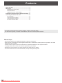
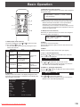
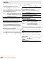
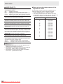
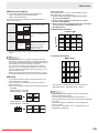
PN-425
LCD MONITOR
OPERATION GUIDE
Downloaded From TV-Manual.com Manuals
Contents
Basic Operation................................................................3
Menu Items........................................................................5
Displaying the menu screen..........................................5
Menu item details..........................................................6
Adjustments for PC screen display.............................10
Initialization (Reset)/Functional Restriction Setting.... 11
Controlling the Monitor with a PC.................................12
PC connection.............................................................12
Communication conditions..........................................12
Communication procedure..........................................12
RS-232C command table............................................14
This guide contains instructions regarding operation, settings, and similar details.
For instructions regarding connection and installation, refer to the included Operation Manual.
Manual Scope
- Microsoft and Windows are registered trademarks of Microsoft Corporation.
- Adobe, Acrobat, and Reader are either registered trademarks or trademarks of Adobe Systems Incorporated in the United
States and/or other countries.
- All other brand and product names are trademarks or registered trademarks of their respective holders.
- Language of OSD menu used in this manual is English by way of example.
- Illustrations in this manual may not exactly represent the actual product or display.
- This manual assumes use in horizontal orientation, except where specifically noted.
2
E
Downloaded
From TV-Manual.com Manuals
Basic Operation
3. MODE (Screen mode selection)
Each time you press this button, the screen mode changes in
the following order:
1
STD (Standard) → OFFICE*1 → VIVID → sRGB*2
→ STD (Standard) ...
3
2
*1Display brightness is lowered. (This mode saves power.)
*2When the input mode is DIGITAL/ANALOG1/ANALOG2.
sRGB is international standard of color representation
specified by IEC (International Electrotechnical
Commission). Color conversion is made in taking account
of liquid crystal’s characteristics and represents color tone
close to its original image.
4
6
5
7
8
4. SIZE (Screen size selection)
Each time you press this button, the screen size changes in
the following order: (See page 4.)
WIDE → ZOOM1 → ZOOM2 → NORMAL
→ Dot by Dot → WIDE ...
1. INPUT (Input mode selection)
The menu is displayed. Press
or
to select the input
mode, and press
to enter.
* You can select the input terminal by pressing the input
switch of the monitor.
Input mode
DIGITAL
ANALOG1
PC
input
ANALOG2
AV
input
Video
Audio
PC digital RGB input
terminal
PC analog RGB input
terminal
PC audio input
terminal
Audio input
terminals (VIDEO)
2. DISPLAY
Displays monitor information. The display disappears when
this button is pressed again or disappears automatically after
approximately 15 seconds.
INFORMATION
ANALOG1
INPUT MODE
: ANALOG1
SIZE
: WIDE
MODE
: STD
BRIGHT
: 22
VOLUME
: 15
OFF TIMER
: 10:59
ID No.
:
MODEL
: PN-425
S/N
:
1024x768
V: 60 Hz
Pressing
or
displays the VOLUME menu when the
menu screen is not displayed.
VOLUME
Audio input
Component video input
terminals
COMPONENT
terminals
(COMPONENT)
VIDEO
6. MENU
Displays and turns off the menu screen (see page 5).
7. VOL +/- (Volume adjustment)
PC analog RGB input
terminals (BNC)
Composite video input
terminals or S-video
input terminal
5. MUTE
Turns off the volume temporarily.
Press the MUTE button again to turn the sound back to the
previous level.
15
Press
or
to adjust the volume of the sound.
* If you do not press any buttons for about 4 seconds, the
VOLUME menu automatically disappears.
8. BRIGHT +/- (Backlight adjustment)
Pressing
or
displays the BRIGHT menu when the menu
screen is not displayed.
BRIGHT
15
Press
or
to adjust the brightness.
* If you do not press any buttons for about 4 seconds, the
BRIGHT menu automatically disappears.
0
Downloaded From TV-Manual.com Manuals
H: 48.4 kHz
3
E
Basic Operation
nSwitching the screen size
Even when the screen size is changed, the display may remain the same depending on the input signal.
WIDE
ZOOM1
PC input
Displays image so it fills the entire screen.
AV input
An image with a 4:3 aspect ratio is stretched to fill the entire
screen.
PC input
An image with a 4:3 aspect ratio is enlarged to fill the entire screen
without changing the aspect ratio. The edges of the image may be
cut off.
AV input
ZOOM2
PC input
Use this size if ZOOM1 cuts off the subtitles.
AV input
NORMAL
Dot by Dot
PC input
Displays image so it fills the screen without changing the aspect
ratio of the input signals.
AV input
Displays the entire image of the aspect ratio of 4:3 without
changing the aspect ratio.
PC input
Displays the dots of the signals input from the connected PC as
the corresponding dots on the screen.
AV input
Displays the dots of the input signals as the corresponding dots on
the screen. *
* Displays 1080i images at reduced size so that they fill the entire screen.
TIPS
• Using this monitor’s screen-size switching or dual-screen display functions to compress or expand the screen for commercial
or public viewing in establishments like cafes or hotels may infringe on the rights of the creators, as protected by Copyright
Law, so please be careful.
• When ENLARGE is set, the screen size is fixed to WIDE mode.
• When dual-screen display is selected, the screen size cannot be changed.
• The appearance of the original video may change if you select a screen size with a different aspect ratio than the original
image (e.g. TV broadcast or video input from external equipment).
• When an ordinary non-wide image (4:3) is viewed with the whole screen using the screen-size switching function of this
monitor, the edge of the image may be lost or appear distorted. If you wish to respect the creator’s intentions, set the screen
size to NORMAL.
• When playing commercial software, parts of the image (like subtitles) may be cropped. In this case select the optimal screen
size using the screen-size switching function of this monitor. With some software, there may be noise or distortion at the
edges of the screen. This is due to the characteristics of the software, and is not a malfunction.
• Depending on the original image size, black bands may remain at the edges of the screen.
4
E
Downloaded
From TV-Manual.com Manuals
Menu Items
Displaying the menu screen
nMenu screen display
1
Video and audio adjustment and settings of various functions
are enabled. This section describes how to use the menu
items. See pages 6 to 8 for details of each menu items.
GAIN CONTROL
MANUAL
nExample of operation
(Adjusting CONTRAST in the GAIN CONTROL menu)
1. Press
to display the menu screen.
ADJUSTMENT
MANUAL
127
50
149
27
H-POS
V-POS
V: 60 Hz
H: 48.4 kHz
2. Press
to display the GAIN CONTROL menu.
3. Press
to select CONTRAST.
GAIN CONTROL
44
4
1024x768
V: 60 Hz
H: 48.4 kHz
TIPS
• Items that cannot be selected appear in gray.
(e.g. Function not supported by the current input signal)
ANALOG1
BLACK LEVEL
68
CONTRAST
44
1024x768
V: 60 Hz
or
H: 48.4 kHz
to adjust the setting.
GAIN CONTROL
MANUAL
ANALOG1
AUTO
BLACK LEVEL
68
CONTRAST
50
1024x768
5. Press
68
CONTRAST
AUTO
MANUAL
4. Press
BLACK LEVEL
3
1 Name of the menu
2 Input mode
3 An item being selected (highlighted)
4 Screen resolution of input signal, and other data.
RESET
1024x768
ANALOG1
AUTO
ANALOG1
AUTO
CLOCK
PHASE
●
2
V: 60 Hz
H: 48.4 kHz
to close the menu screen.
TIPS
• The menu will differ depending on the input mode.
• The menu screen will close automatically if no operation is
performed for about 15 seconds.
Downloaded From TV-Manual.com Manuals
5
E
Menu Items
Menu item details
The menu will differ depending on the input mode.
nADJUSTMENT (ANALOG1/ANALOG2)
MANUAL/AUTO
Adjusts CLOCK, PHASE, H-POS, and V-POS.
If you are using a Windows PC, use the adjustment pattern
on the supplied CD-ROM. (See page 10.)
MANUAL����� Selects and adjusts CLOCK, PHASE, H-POS,
and V-POS.
AUTO���������� Use this automatic adjustment when you use
the PC analog RGB input terminal or PC analog
RGB input terminals (BNC) to display a PC
screen for the first time or when you change the
setting of the PC. (See page 10.)
CLOCK
Adjusts frequency for sampling clock for applicable video.
Adjust when there is flickering in the form of vertical stripes.
When using the adjustment pattern (see page 10), make
adjustments so that no vertical stripe noise appears in it.
PHASE
Adjusts sampling clock phase for applicable video.
Useful when small characters appear with low contrast and/
or there are flickers at corners.
When using the adjustment pattern (see page 10), make
adjustments so that no horizontal stripe noise appears in it.
* Adjustments to PHASE should be made only after CLOCK
has been correctly set.
H-POS
Adjust the horizontal position of the image.
V-POS
Adjust the vertical position of the image.
RESET
resets the values of the ADJUSTMENT menu
Pressing
items to the factory preset values.
nGAIN CONTROL
(DIGITAL/ANALOG1/ANALOG2)
MANUAL/AUTO (ANALOG1/ANALOG2)
Adjusts BLACK LEVEL and CONTRAST.
If you are using a Windows PC, use the adjustment pattern
on the supplied CD-ROM. (See page 10.)
MANUAL����� Selects and adjusts BLACK LEVEL and
CONTRAST.
AUTO���������� Automatically adjusts BLACK LEVEL and
CONTRAST.
BLACK LEVEL
Adjusts the entire brightness of the video signals.
CONTRAST
Adjusts the brightness of the image.
nCOLOR CONTROL
(DIGITAL/ANALOG1/ANALOG2)
WHITE BALANCE
THRU�������������� Displays the input signal level as is.
(for DIGITAL only)
PRESET��������� Selects the color temperature using PRESET.
USER�������������� Used for adjusting R-CONTRAST,
G-CONTRAST, and B-CONTRAST
respectively.
PRESET
Allows selection from the preadjusted settings. (For a guide
to the color temperatures of the adjustment values, see page
8.)
R-CONTRAST
Adjusts red component when WHITE BALANCE is set to
USER.
G-CONTRAST
Adjusts green component when WHITE BALANCE is set to
USER.
B-CONTRAST
Adjusts blue component when WHITE BALANCE is set to
USER.
COPY TO USER
SET������������� Pressing
copies the value set for PRESET
to the USER setting.
GAMMA
Select a gamma value.
6
E
Downloaded
From TV-Manual.com Manuals
Menu Items
nVIDEO ADJUSTMENT
(COMPONENT/VIDEO)
CONTRAST
Adjusts the light areas of the image.
BLACK LEVEL
Adjusts the entire brightness of the video signals.
TINT
Adjusts the hue. Selecting + changes the color towards
green, and selecting - changes it towards magenta.
COLORS
Adjusts the color intensity.
SHARPNESS
Adjusts the sharpness of the image.
WHITE BALANCE
Allows selection from the preadjusted settings. (For a guide
to the color temperatures of the adjustment values, see page
8.)
GAMMA
Select a gamma value.
nMODE SELECT 1
480 LINES (ANALOG1/ANALOG2)
If a computer connected to the PC analog RGB input
terminal or the PC analog RGB input terminals (BNC)
outputs resolutions of 640 x 480 or 848 x 480, select the
relevant horizontal resolution.
768 LINES (ANALOG1/ANALOG2)
If a computer connected to the PC analog RGB input
terminal or the PC analog RGB input terminals (BNC)
outputs resolutions of 1024 x 768, 1280 x 768, or 1360 x
768, select the relevant horizontal resolution.
ENLARGE H
Sets the number of screen splits (number of monitors) in the
longer direction used for the enlargement. (See page 9.)
ENLARGE V
Sets the number of screen splits (number of monitors) in the
shorter direction used for the enlargement. (See page 9.)
ENLARGE-POS H/ENLARGE-POS V
Specify the split screen to be displayed when the
enlargement function is used. (See page 9.)
BEZEL H/BEZEL V
Sets the frame width of the display when the enlargement
function is used.
(H: Width of the shorter side, V: Width of the longer side)
MULTI ZOOM
nMODE SELECT 2
OFF TIMER
Set the time until the monitor turns off (enters standby mode)
between 0 and 23 in units of one hour. This function is
disabled when “0” is specified.
OSD H-POSITION
Adjusts the horizontal display position of menu screen.
OSD V-POSITION
Adjusts the vertical display position of menu screen.
LANGUAGE
Sets the display language for the menu screen.
Pressing
displays the selection menu.
POWER ON DELAY
You can delay the screen display after the monitor is turned
on. The period can be set up to 60 seconds in units of one
second. When this function is activated, the power LED
flashes in orange. This function is disabled when “0” is
specified.
ID No. SET
Assigns ID numbers to monitors using RS-232 cables.
The numbers 1 to 255 are available for ID numbers.
If “0” is set, the system regards this as the state where no ID
number is set.
This should normally be set to “0”.
MONITOR
Select the installation direction of the monitor.
LANDSCAPE......Horizontal orientation
PORTRAIT.........Vertical orientation
SCAN MODE (COMPONENT/VIDEO)
Sets the scan mode used for AV mode input.
MODE1����Over-scan display
MODE2����Under-scan display
MODE3����Under-scan display when the input signal is 1080i.
Otherwise, over-scan display
* Even when MODE1 is selected, under-scan display is used
when the input signal is 1080i and the screen size is Dot by
Dot.
COLOR SYSTEM
Selects the video signal system for AV equipment connected
to the S-video input terminal and composite video input
terminals (PAL/PAL-60/SECAM/NTSC (3.58)/NTSC (4.43)). If
AUTO is selected, the system is automatically set according
to the input signal.
Adjusts the enlarged screen. Pressing
displays the next
menu.
IMAGE ZOOM��Adjusts the scale of enlargement.
H-POS��������������Adjusts the position of the longer direction.
V-POS��������������Adjusts the position of the shorter direction.
AUDIO
Adjust the volume of the sound output from the speaker.
Pressing
displays the next menu.
TREBLE�����������Adjusts the volume of treble-level sound.
BASS����������������Adjusts the volume of bass-level sound.
BALANCE���������Adjusts the balance of the audio sound
between right and left.
Downloaded From TV-Manual.com Manuals
7
E
Menu Items
nMODE SELECT 3
PIP MODES (See page 9.)
Sets the display method.
OFF���������Displays one screen.
PIP�����������Displays a sub screen inside a main screen.
PbyP��������Displays a main screen and a sub screen in a line.
PbyP2������Displays a main screen which measures 1024 pixels
in the longer direction and a sub screen in a line.
PIP SIZE
Sets the size of the sub screen in PIP mode.
PIP H-POS
Adjusts the horizontal position of the sub screen in PIP mode.
PIP V-POS
Adjusts the vertical position of the sub screen in PIP mode.
PIP SOURCE (VIDEO)
Selects the input signal of the sub screen in PIP, PbyP, or
PbyP2 mode.
SOUND CHANGE
Sets the sound which is output in PIP, PbyP, or PbyP2 mode.
If the main screen is displayed as a full screen by the AUTO
OFF function, the sound for the main screen is output even
when the sound for the sub screen is specified.
PbyP2 POS
Sets the position of the sub screen in PbyP2 mode.
AUTO OFF
Sets the display method when no signals for the sub screen
are input in PIP, PbyP, or PbyP2 mode.
AUTO............. Displays the main screen as a full screen.
MANUAL........ Displays a main screen and a black sub screen.
TIPS
• When WHITE BALANCE is set to THRU, BLACK LEVEL,
CONTRAST and GAMMA cannot be set.
• When MODE is set to sRGB or VIVID, COLOR CONTROL
cannot be set. (DIGITAL/ANALOG1/ANALOG2)
• When MODE is VIVID, WHITE BALANCE and GAMMA
cannot be set. (COMPONENT/VIDEO)
8
E
Downloaded
From TV-Manual.com Manuals
nGuide to the color temperatures of the
adjustment values
The following is a guide to the color temperatures of the
respective adjustment values for WHITE BALANCE.
• Factory-adjusted value is “13” (approx. 9,000K).
• The setting values are shown for reference. The color
temperature of the screen varies over time. This function is
not intended to keep the color temperature constant.
Adjustment value
Color temperature (K)
15
app. 10,000
14
app. 9,500
13
app. 9,000
12
app. 8,500
11
app. 8,000
10
app. 7,500
9
app. 7,000
8
app. 6,500
7
app. 6,000
6
app. 5,500
5
app. 5,000
4
app. 4,500
3
app. 4,000
2
app. 3,500
1
app. 3,000
Menu Items
nDual screen display
You can display the following screens simultaneously.
• VIDEO and DIGITAL/ANALOG1/ANALOG2
• VIDEO and COMPONENT
Set this function with PIP MODES in the MODE SELECT 3
menu. (See page 8.)
PIP
A sub screen is displayed
inside a main screen.
Main screen
Sub
screen
PbyP
Sub
screen
PbyP2
Main screen
Sub
screen
In horizontal orientation
A main screen and a sub
screen are displayed in a
line.
Displays a main screen
which measures 1024
pixels in the longer
direction and a sub
screen in a line.
ENLARGE H
1
ENLARGE V
Main
screen
Setting procedure
In the MODE SELECT 1 menu, set ENLARGE H/V and
ENLARGE-POS H/V. (See page 7.)
1. Set the number of monitors aligned in the longer
direction in ENLARGE H.
2. Set the number of monitors aligned in the shorter
direction in ENLARGE V.
3. Set the section of the separated image to be displayed
on each monitor in ENLARGE-POS H and
ENLARGE-POS V.
2
3
4
1
(1,1)
(2,1)
(3,1)
(4,1)
2
(1,2)
(2,2)
(3,2)
(4,2)
3
(1,3)
(2,3)
(3,3)
(4,3)
4
(1,4)
(2,4)
(3,4)
(4,4)
* The currently selected input signal is displayed on the main
screen.
TIPS
In vertical orientation
ENLARGE V
4
3
2
1
(1,4)
(1,3)
(1,2)
(1,1)
1
(2,4)
(2,3)
(2,2)
(2,1)
2
(3,4)
(3,3)
(3,2)
(3,1)
3
(4,4)
(4,3)
(4,2)
(4,1)
4
ENLARGE H
• You might infringe on a copyright of the author which is
protected by copyright law when you display the images of
the computer screen and television/VCR simultaneously for
profit-making or to show the image to the public.
• The screen size for dual-screen display is the same as
the screen size for single-screen display. The Dot by Dot
screen is displayed in NORMAL size except when it is set
as the PIP main screen.
• When dual-screen display is selected, the screen cannot
be enlarged. MONITOR settings cannot be changed either.
nEnlarge
• You can align several monitors and integrate them into a
single large screen to display.
• Up to 4 monitors can be aligned in both the longer and
shorter directions.
• Each monitor displays enlarged views of separated images.
(Example)
Longer direction: 2 monitors
Shorter direction: 2 monitors
Longer direction: 3 monitors
Shorter direction: 2 monitors
Downloaded From TV-Manual.com Manuals
* The numbers in parentheses are the setting values in
(ENLARGE-POS H, ENLARGE-POS V) format.
TIPS
• Up to 4 monitors can be linked in daisy chain using PC
analog RGB output terminals.
• For connections other than those indicated above, a
separate splitter for the video signal (commercially available)
is required.
• Dual-screen display is disabled when the enlargement
function is used.
• To cancel the enlargement, set “1” for ENLARGE H and
ENLARGE V respectively.
9
E
Menu Items
Adjustments for PC screen display
nAutomatic adjustment
When you use the PC analog RGB input terminal or PC
analog RGB input terminals (BNC) to display a PC screen for
the first time, or when you change the setting of the PC, use
the automatic screen adjustment.
1. Switch the input to ANALOG1 or to ANALOG2 and
display the adjustment pattern. (See the description
below.)
2. Press
to display the ADJUSTMENT menu.
and select AUTO.
3. Press
The automatic adjustment is complete in several seconds.
4. Press
6 times to close the menu screen.
TIPS
• If the screen cannot be adjusted properly with one
automatic adjustment, repeat the automatic adjustment 2 or
3 times. Try manual adjustment if necessary.
nScreen display for adjustment
Before making adjustments in the ADJUSTMENT menu
or GAIN CONTROL menu, display an image to brighten
the entire screen. If you are using a Windows PC, use the
adjustment pattern on the supplied CD-ROM.
Opening the adjustment pattern
1. Load the supplied CD-ROM into the computer’s CDROM drive.
2. Open the CD-ROM in [My Computer].
3. Double-click [Adj_uty.exe].
The adjustment pattern will appear.
Adjust the screen automatically or manually.
4. When adjustment is finished, press the [Esc] on the
computer’s keyboard to quit the adjustment program.
5. Eject the CD-ROM from the CD-ROM drive.
TIPS
• If the display mode on the computer you are using is
65,000 colors, the color levels in the color pattern may
appear differently or grayscale may appear to be colored.
(This is due to the specifications of the input signal and is
not a malfunction.)
10
E
Downloaded
From TV-Manual.com Manuals
Initialization (Reset)/Functional Restriction Setting
You can return the settings to their factory-preset values and
restrict operations.
1. After pressing
, and
for about 5 seconds, press
,
,
in that order.
FUNCTION 1
ALL RESET
ALL RESET
ADJUSTMENT LOCK
OFF
1
OSD DISPLAY
OFF
ON
LED
OFF
ON
TEMP ALERT
OFF
OSD&LED
RS-232C
LOCKED
2
LED
UNLOCKED
OK...[MENU]
2. Select and set the items.
ALL RESET
Resets the settings to the factory default settings.
After initialization, turn the main power switch off and
then back on.
ADJUSTMENT LOCK
You can disable operations on the monitor and the
remote control unit that use buttons.
OFF���Enables operation.
1��������Disables all operations other than turning power
on/off and FUNCTION 1.
2��������Only the FUNCTION 1 operation is enabled.
Disables all operations other than FUNCTION 1
(not even power on/off).
OSD DISPLAY
Hides/shows menus.
The FUNCTION 1 screen cannot be hidden.
LED
Specifies whether to light power LED.
TEMP ALERT
Selects the notification method for an abnormal
temperature.
OFF�������������� Do not notify about an abnormal
temperature.
OSD&LED���� When an abnormal temperature is
detected, the power LED flashes in red
and green alternately and the screen
displays a message: TEMPERATURE.
LED�������������� When an abnormal temperature is
detected, the power LED flashes in red
and green alternately.
RS-232C
Specifies whether to allow control via RS-232C (see
page 12).
LOCKED������� Disables control via RS-232C.
UNLOCKED� Enables control via RS-232C.
3. Press
to return to the normal screen.
Downloaded From TV-Manual.com Manuals
11
E
Controlling the Monitor with a PC
You can control this monitor from a PC via RS-232C (COM
port) on the PC.
Communication procedure
PC connection
When a command is sent from the PC to the monitor, the
monitor operates according to the received command and
sends a response message to the PC.
Connect with RS-232 straight cable between the PC’s COM
port (RS-232C connector) and the RS-232C input terminal on
the monitor.
nCommand format
Return code
C1
C2
C3
C4
P1
Command field
(4 prescribed
alphanumerical characters)
P2
P3
P4
Parameter field
(4 character string comprised of:
0-9, +, -, space, ?)
Example: VOLM0030
VOLM
30
RS-232C input terminal
PC
To COM port
RS-232 straight cable
(commercially available)
* Be sure to input 4 characters for the parameter. Pad with
spaces (“ ”) if necessary.
(“
” is a return code (0DH, 0AH or 0DH))
Wrong : VOLM30
Right : VOLM
30
When inputting a negative value, specify a numerical value in
3 digits.
Example: AUTR-009
Communication conditions
Set the RS-232C communication settings on the PC to match
the monitor’s communication settings as follows:
Baud rate
9600 bps
Stop bit
1 bit
Data length
8 bits
Flow control
None
Parity bit
None
Do not use spaces for MPOS. Specify parameters using 6
numerical characters.
Example: MPOS010097
If a command has “R” listed for “Direction” in the
“RS-232C command table” on page 14, the current value can
be returned by using “?” as the parameter.
Example:
VOLM ? ? ? ?
←
From PC to monitor (How much
is current volume setting?).
30
←
From monitor to PC (Current
volume setting: 30).
* If an ID number (see page 7) has been assigned
(For example, ID number = 1).
VOLM
30
12
E
Downloaded
From TV-Manual.com Manuals
001
?
← From PC to monitor.
← From monitor to PC.
Controlling the Monitor with a PC
nResponse code format
When a command has been executed correctly
O
K
Return code
(0DH, 0AH)
A response is returned after a command is executed.
When a command has not been executed
E
R
R
Return code
(0DH, 0AH)
TIPS
• “ERR” is returned when there is no relevant command or
when the command cannot be used in the current state of
the monitor.
• If communication has not been established for reasons
such as a bad connection between the PC and monitor,
nothing is returned (not even ERR).
If execution of the command is taking some time
W
A
I
T
Return code
(0DH, 0AH)
“WAIT” is returned. In this case, a value will be returned if you
wait a while. Do not send any command during this period.
When control via RS-232C is locked (to prevent use)
using the operation lock function (see page 11)
L
O
C
K
E
D
Return code
(0DH, 0AH)
nCommunication interval
• After OK or ERR is returned, you must send the following
commands.
To set a timeout for the command response, specify 10
seconds or longer.
• Provide an interval of 100 ms or more between the
command response and the transmission of the next
command.
VOLM0020
OK
Interval of 100 ms or more
INPS0001
WAIT
OK
TIPS
• When turning the power on while the POWER ON DELAY
function is in use, set the timeout period to the POWER ON
DELAY period + 10 seconds or longer.
Downloaded From TV-Manual.com Manuals
13
E
Controlling the Monitor with a PC
RS-232C command table
How to read the command table
Command:
Command field (See page 12.)
Direction:
W When the “Parameter” is set in the parameter field (see page 12), the command functions as described
under “Control/Response Contents”.
?” in the
R The returned value indicated under “Reply” can be obtained by setting “????” or “
parameter field (see page 12).
Parameter:
Parameter field (See page 12.)
Reply:
Response (Returned value)
*:
“Yes” indicates a command which can be used in power standby mode.
“No” indicates a command which cannot be used in power standby mode.
TIPS
• To specify the horizontal/vertical positions for vertical orientation, specify the values for horizontal orientation.
Power control/Input mode selection
Function
Power control
Command
POWR
Direction
Parameter
W
Reply
0
Control/Response contents
*
Switches to standby mode.
1
Returns from standby mode.
R
0 Standby mode
Yes
1 Normal mode
2 Input signal waiting mode
Input mode selection
INPS
W
0
Toggle change for input mode.
1
DIGITAL: DVI
2
ANALOG1: Analog RGB
3
COMPONENT: Component
4
VIDEO: S-Video/Video
5
Reserved (ERR code returned)
6
ANALOG2: Analog RGB (BNC)
R
Yes
1 DIGITAL: DVI
2 ANALOG1: Analog RGB
3 COMPONENT: Component
4 VIDEO: S-Video/Video
6 ANALOG2: Analog RGB (BNC)
Video adjustment (When PC digital RGB input is used: DIGITAL)
Function
WHITE BALANCE
GAIN CONTROL
THRU
Parameter
Reply
0
PRESET
1-15
1-15
USER
99
99
Control/Response contents
*
Yes
R-CONTRAST
CRTR
WR
0-128
0-128
G-CONTRAST
CRTG
WR
0-128
0-128
B-CONTRAST
CRTB
WR
0-128
0-128
BLACK LEVEL
BLVL
WR
0-60
0-60
CONTRAST
CONT
WR
0-60
0-60
GAMM
WR
0-2
0-2
0: 1.8, 1: 2.2, 2: 2.4
Yes
PXCK
R
-
Returns current resolution in the form of hhh, vvv.
No
WIDE
WR
1
1
WIDE
2
2
NORMAL
3
3
Dot by Dot
4
4
ZOOM1
5
5
ZOOM2
Resolution check
SIZE (Screen size selection)
14
Direction
WR
0
GAMMA
Input resolution
Command
CTMP
E
Downloaded
From TV-Manual.com Manuals
Yes
Yes
Controlling the Monitor with a PC
Video adjustment
(When PC analog RGB/PC analog RGB (BNC) inputs are used: ANALOG1/ANALOG2)
Function
ADJUSTMENT
GAIN CONTROL
WHITE BALANCE
Command
Direction
Control/Response contents
Reply
ASNC
W
1
CLOCK
CLCK
WR
0-255
0-255
PHASE
PHSE
WR
0-63
0-63
H-POS
HPOS
WR
0-500
0-500
Adjusts the position of the longer direction. Maximum value depends on
resolution.
V-POS
VPOS
WR
0-100
0-100
Adjusts the position of the shorter direction.
RESET
ARST
W
1
AUTO
AGIN
W
1
BLACK LEVEL
BLVL
WR
0-127
0-127
CONTRAST
CONT
WR
0-127
0-127
PRESET
CTMP
WR
1-15
1-15
99
99
USER
CRTR
WR
0-128
0-128
G-CONTRAST
CRTG
WR
0-128
0-128
B-CONTRAST
CRTB
WR
0-128
0-128
GAMM
WR
0-2
Resolution check
PXCK
R
Pixel setting
PXSL
WR
SIZE (Screen size selection)
WIDE
WR
*
No
No
R-CONTRAST
GAMMA
Input resolution
Parameter
AUTO
Yes
Yes
0-2
0: 1.8, 1: 2.2, 2: 2.4
-
Returns current resolution in the form of hhh, vvv.
Yes
0
0
768) Reserved (ERR code returned)
1
1
768) 1360 x 768
2
2
768) 1280 x 768
3
3
768) 1024 x 768
4
4
480) Reserved (ERR code returned)
5
5
480) 848 x 480
6
6
480) 640 x 480
1
1
WIDE
2
2
NORMAL
3
3
Dot by Dot
4
4
ZOOM1
5
5
ZOOM2
No
Yes
Video adjustment
(When component video/composite video inputs are used: COMPONENT/VIDEO)
Function
VIDEO
ADJUSTMENT
CONTRAST
Command
Direction
Parameter
Control/Response contents
Reply
CONT
WR
0-60
0-60
BLACK LEVEL
BLVL
WR
0-60
0-60
COLORS
COLR
WR
0-60
0-60
TINT
TINT
WR
0-60
0-60
SHARPNESS
SHRP
WR
0-20
0-20
WHITE BALANCE
CTMP
WR
1-15
1-15
GAMMA
GAMM
WR
0-2
0-2
0: 1.8, 1: 2.2, 2: 2.4
SIZE (Screen size selection)
WIDE
WR
1
1
WIDE
SCAN MODE
Resolution check
RESO
R
SCAN
WR
Downloaded From TV-Manual.com Manuals
Yes
2
2
ZOOM1
3
3
ZOOM2
4
4
NORMAL
5
Input resolution
0-2
*
Yes
Yes
5
Dot by Dot
-
480i, 480p, 1080i, 720p, 576i, 576p
No
0-2
0: MODE1, 1: MODE2, 2: MODE3
Yes
15
E
Controlling the Monitor with a PC
Common input controls
Function
PIP
PbyP
PbyP2
PIP MODES
PIP SIZE
Sub screen position
Direction
WR
MWSZ
WR
Parameter
0
Control/Response contents
Reply
0
1
1
PIP
2
2
PbyP
3
3
PbyP2
0
0
SMALL
1
1
MEDIUM
2
2
LARGE
WR
0-100
0-100
Adjusts the position of the longer direction.
MVPS
WR
0-100
0-100
Adjusts the position of the shorter direction.
Sub screen position
(Batch specification)
MPOS
WR
0-100,0-100
0-100,0-100
Specify the position in MPOSxxxyyy format (xxx: Longer side, yyy:
Shorter side position). Returns a response in (xxx,yyy) format.
PIP SOURCE
MWIP
WR
1
1
DIGITAL: DVI
PbyP2 POS
AUTO OFF
MWAD
MW2P
MOFF
WR
WR
WR
2
2
ANALOG1: Analog RGB
3
3
COMPONENT: Component
4
4
VIDEO: S-Video/Video
5
-
Reserved (ERR code returned)
6
6
ANALOG2: Analog RGB (BNC)
1
1
MAIN
2
2
SUB
0
0
POS1
1
1
POS2
2
2
POS3
0
0
MANUAL
1
1
AUTO
TREBLE
AUTR
WR
-10-10
-10-10
BASS
AUBS
WR
-10-10
-10-10
BALANCE
AUBL
WR
-10-10
-10-10
VOLUME
VOLM
WR
0-31
0-31
MUTE
WR
0
0
OFF
1
1
ON
ID number
OFTM
ID no. setting
WR
OFTR
R
IDST
W
0
0
OFF
1-23
Set time for OFF TIMER
Value
Remaining time
R
ID no. setting (Once)
IDSL
ID no. setting (Subsequent) IDLK
INFORMATION
W
W
Sets the monitor’s ID number. (“0” means “no ID number”.) Automatically
set with IDST001+.
0-255
Sets a monitor ID number.
This ID number is only effective for the command immediately after this
command.
0
Clears the ID number if one has been designated.
1-255
Sets a monitor ID number.
This ID number is effective for the next and all subsequent commands
after this command.
0
Clears the ID number if one has been designated.
IDCK
W
MODEL
INF1
R
Value
S/N
SRNO
R
Value
BMOD
WR
MODE (Screen mode selection)
0
ID: xxx
IDLK: yyy
Displays the product serial number.
0
0
STD (Standard)
1
1
OFFICE
2
2
VIVID
3
3
sRGB (When the input mode is ANALOG1/ANALOG2/DIGITAL)
0-31
Brightness
0
OSD ON
BRIGHT
VLMP
WR
0-31
RSET
W
0
OSD DISPLAY
LOSD
WR
0
1
1
OSD OFF
ADJUSTMENT LOCK
ALCK
WR
0
0
OFF
TEMP ALERT
POWER ON DELAY
16
OFLD
TALT
PWOD
E
Downloaded
From TV-Manual.com Manuals
WR
WR
WR
Yes
Yes
Yes
Yes
Yes
No
No
Yes
Yes
Yes
Displays monitor’s own ID number and the selected ID number on the
screen.
ALL RESET
LED (Power LED)
Yes
Returns the monitor’s ID number.
1-255
ID check
Yes
Yes
1-23
0-255
Yes
Yes
MUTE
OFF TIMER
*
OFF
MHPS
SOUND CHANGE
AUDIO
Command
MWIN
Yes
Yes
Yes
No
1
1
1
2
2
2
0
0
LED ON
1
1
LED OFF
0
0
TEMP ALERT OFF
1
1
TEMP ALERT OSD&LED
2
2
TEMP ALERT LED
0
0
POWER ON DELAY OFF
1-60
1-60
POWER ON DELAY ON
Yes
Yes
Yes
Yes
Yes
Controlling the Monitor with a PC
Function
LANGUAGE
Command
Direction
LANG
WR
Parameter
14
DSTA
1
1
DEUTSCH
2
FRANÇAIS
3
3
ITALIANO
R
*
ENGLISH
2
4
Temperature sensor
Control/Response contents
Reply
14
4
ESPAÑOL
0
Internal temperature normal
1
Internal temperature abnormal (Standby mode)
2
Internal temperature abnormal (Temperature is normal now, but it was
abnormal during operation.)
3
Internal temperature abnormal (Brightness of the backlight decreases.)
Yes
Yes
4
Temperature sensor abnormal
Temperature
ERRT
R
Value
Returns temperature at temperature sensors 1 and 2 in the form of xxx,
yyy.
Fan error monitoring
ERRF
R
0
Fan normal
1
Fan error
COLOR SYSTEM
CSYS
WR
0-5
0-5
0: AUTO, 1: PAL, 2: PAL-60, 3: SECAM, 4: NTSC 3.58, 5: NTSC 4.43
Yes
STDR
WR
0-1
0-1
0: LANDSCAPE, 1: PORTRAIT
Yes
EMAG
WR
0
0
OFF
MONITOR
ENLARGE
Ratio
BEZEL H
1
1
2x2
2
2
3x3
3
3
4x4
EMHV
WR
00-44
00-44
1 x 1 (OFF) to 4 x 4 (“m x n” is expressed as “mn”, where m and n are
the numbers of monitors specified for the longer direction and the shorter
direction respectively.)
BEZH
WR
0-100
0-100
Bezel width of shorter side
BEZEL V
BEZV
WR
0-100
0-100
Bezel width of longer side
Image position (M x N)
EPHV
WR
11-44
11-44
Specify values in the order of ENLARGE-POS H/ENLARGE-POS V. (See
page 9.)
See the description below.
Image position (2 x 2)
EPOS
WR
0-3
0-3
Image position (3 x 3)
EPOS
WR
0-8
0-8
0-15
Image position (4 x 4)
Obtain cause of last standby mode
EPOS
WR
0-15
STCA
W
0
No
Yes
No
Initialization
R
0
No detectable error has occurred
1
Standby mode by remote control unit
2
Standby mode by monitor button
3
Standby mode by RS-232C
4
Waiting mode by NO SIGNAL (Incl: VESA DPMS/DMPM)
5
Standby mode by fan error
6
Standby mode by abnormal temperature
7
Standby mode by OFF TIMER operation
Yes
• Image position (EPOS) setting
In horizontal orientation
2x2
3x3
4x4
0
1
0
1
2
0
2
3
3
4
5
4
6
7
8
8
12
3
1
2
5
6
7
9
10
11
13
14
15
In vertical orientation
2x2
2
0
3
1
3x3
4x4
6
3
0
7
4
1
8
5
2
12
13
14
15
Downloaded From TV-Manual.com Manuals
0
8
4
9
5
1
10
6
2
11
7
3
17
E
PN-425 G EN08K(1)
Downloaded From TV-Manual.com Manuals