1
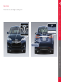
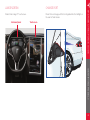
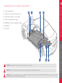
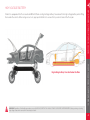
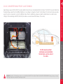
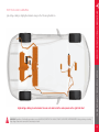
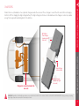
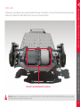
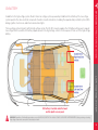
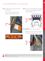
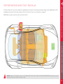
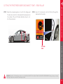
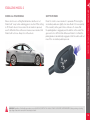
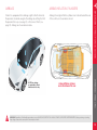
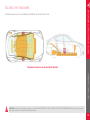
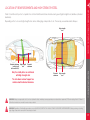
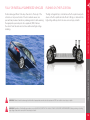
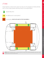
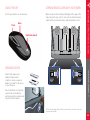
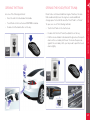
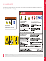
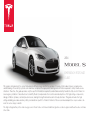
2014 EMERGENCY RESPONSE GUIDE This guide is intended only for use by trained and certified rescuers and first responders. It assumes that readers have a comprehensive understanding of how safety systems work and have completed the appropriate training and certification required to safely handle rescue situations. Therefore, this guide provides only the specific information required to understand and safely handle the fully electric Model S in an emergency situation. It describes how to identify Model S, and provides the locations and descriptions of its high voltage components, airbags, inflation cylinders, seat belt pre-tensioners, and high strength materials used in its body structure. This guide includes the high voltage disabling procedure and any safety considerations specific to Model S. Failure to follow recommended practices or procedures can result in serious injury or death. The high voltage battery is the main energy source. Model S does not have a traditional gasoline or diesel engine and therefore does not have a fuel tank. IDENTIFYING MODEL S...................................................................................1 LIFTING MODEL S .......................................................................................... 21 HIGH VOLTAGE COMPONENTS ..................................................................3 OPENING MODEL S ...................................................................................... 22 OVERVIEW OF HIGH VOLTAGE COMPONENTS................................................... 3 HIGH VOLTAGE BATTERY ................................................................................................ 4 DC-DC CONVERTER AND FRONT JUNCTION BOX........................................... 5 HIGH VOLTAGE CABLING................................................................................................. 6 CHARGERS................................................................................................................................7 DRIVE UNIT .............................................................................................................................. 8 HIGH VOLTAGE LABELS ............................................................................. 24 LOW VOLTAGE SYSTEM ................................................................................9 INDEX ................................................................................................................. 25 12V BATTERY........................................................................................................................... 9 USING THE KEY ...................................................................................................................22 OPENING DOORS ...............................................................................................................22 OPENING REAR DOORS WITH NO POWER.........................................................22 OPENING THE TRUNK......................................................................................................23 OPENING THE HOOD (FRONT TRUNK) .................................................................23 DISABLING HIGH VOLTAGE........................................................................10 FIRST RESPONDER CUT LOOP - FRONT TRUNK ..............................................10 CUTTING THE FIRST RESPONDER LOOP - FRONT TRUNK .......................... 11 FIRST RESPONDER DISCONNECT POINT - REAR PILLAR............................ 12 CUTTING THE FIRST RESPONDER DISCONNECT POINT REAR PILLAR .........................................................................................................................13 STABILIZING MODEL S ................................................................................. 14 AIRBAGS AND SUPPLEMENTARY RESTRAINT SYSTEM (SRS) ..... 15 AIRBAGS...................................................................................................................................15 AIRBAG INFLATION CYLINDERS.................................................................................15 SEAT BELT PRE-TENSIONERS ......................................................................................16 REINFORCEMENTS ........................................................................................ 17 NO-CUT ZONES............................................................................................... 18 RESCUE OPERATIONS ................................................................................. 19 FULLY OR PARTIALLY SUBMERGED VEHICLES .................................................19 PUSHING ON THE FLOOR PAN ....................................................................................19 P/N: SC-14-94-001.1 TABLE OF CONTENTS FIREFIGHTING ..................................................................................................................... 20 HIGH VOLTAGE BATTERY - FIRE DAMAGE ......................................................... 20 BADGING.....................................................................................................................................1 LARGE SCREEN..................................................................................................................... 2 CHARGE PORT ....................................................................................................................... 2 EMERGENCY RESPONSE GUIDE Model S has three main badges to distinguish it. IDENTIFYING MODEL S BADGING IDENTIFYING MODEL S 1 CHARGE PORT Model S has a large 17” touchscreen. Model S has a charge port that is integrated into the taillight on the rear left side fender. Instrument panel Touchscreen EMERGENCY RESPONSE GUIDE LARGE SCREEN IDENTIFYING MODEL S 2 1. High Voltage Battery 2. DC-DC converter and front junction box 1 2 3 EMERGENCY RESPONSE GUIDE HIGH VOLTAGE COMPONENTS OVERVIEW OF HIGH VOLTAGE COMPONENTS 4 3. High voltage cabling (colored orange) 4. 10 kW on-board master charger 5. OPTIONAL: 10 kW on-board slave charger 6. Charge port 7. Drive unit 6 7 WARNING: After deactivation, the high voltage circuit requires two minutes to deplete. WARNING: The SRS control unit has a backup power supply with a discharge time of approximately ten seconds. HIGH VOLTAGE COMPONENTS 5 WARNING: Regardless of the disabling procedure you use, ALWAYS ASSUME THAT ALL HIGH VOLTAGE COMPONENTS ARE ENERGIZED! Cutting, crushing or touching high voltage components can result in serious injury or death. 3 Model S is equipped with a floor-mounted 400 volt lithium-ion high voltage battery. Never breach the high voltage battery when lifting from under the vehicle. When using rescue tools, pay special attention to ensure that you do not breach the floor pan. HIGH VOLTAGE COMPONENTS High voltage battery is located below the floor EMERGENCY RESPONSE GUIDE HIGH VOLTAGE BATTERY WARNING: Regardless of the disabling procedure you use, ALWAYS ASSUME THAT ALL HIGH VOLTAGE COMPONENTS ARE ENERGIZED! Cutting, crushing or touching high voltage components can result in serious injury or death. 4 High voltage is present at the DC-DC converter and front junction box, located behind the front trunk. The DC-DC converter transforms the high voltage current from the 400 volt battery to low voltage to charge the Model S 12 volt battery. The front junction box provides power to various components, such as the Battery heater, the air conditioning compressor and the cabin heater. Use caution when cutting in this area during a dash lift (dash roll) procedure—use work-around techniques, if necessary. HIGH VOLTAGE COMPONENTS DC-DC converter and front junction box are located behind the front trunk, near the center of the vehicle EMERGENCY RESPONSE GUIDE DC-DC CONVERTER AND FRONT JUNCTION BOX WARNING: Regardless of the disabling procedure you use, ALWAYS ASSUME THAT ALL HIGH VOLTAGE COMPONENTS ARE ENERGIZED! Cutting, crushing or touching high voltage components can result in serious injury or death. 5 High voltage cabling is highlighted in dark orange in the following illustration. HIGH VOLTAGE COMPONENTS High voltage cabling is routed under the rear seats and inside the rocker panel on the right side front EMERGENCY RESPONSE GUIDE HIGH VOLTAGE CABLING WARNING: Regardless of the disabling procedure you use, ALWAYS ASSUME THAT ALL HIGH VOLTAGE COMPONENTS ARE ENERGIZED! Cutting, crushing or touching high voltage components can result in serious injury or death. 6 Model S has one (standard) or two (optional) chargers under the rear seat. These chargers convert the AC current from a charging station to DC for charging the high voltage battery. The high voltage junction box, located between the chargers, routes any surplus energy from regenerative braking back to the battery. OPTIONAL: Slave charger (under rear left side seat) Master charger (under rear right side seat) Charger(s) are located under the rear seat HIGH VOLTAGE COMPONENTS High Voltage Junction Box EMERGENCY RESPONSE GUIDE CHARGERS WARNING: Regardless of the disabling procedure you use, ALWAYS ASSUME THAT ALL HIGH VOLTAGE COMPONENTS ARE ENERGIZED! Cutting, crushing or touching high voltage components can result in serious injury or death. 7 The drive unit is located between the rear wheels under the floor pan of the Model S. It converts the DC current from the high voltage battery into the 3-phase AC current that the electric motor uses to power the wheels. HIGH VOLTAGE COMPONENTS Drive unit is located between the rear wheels EMERGENCY RESPONSE GUIDE DRIVE UNIT WARNING: Regardless of the disabling procedure you use, ALWAYS ASSUME THAT ALL HIGH VOLTAGE COMPONENTS ARE ENERGIZED! Cutting, crushing or touching high voltage components can result in serious injury or death. 8 In addition to the high voltage system, Model S has a low voltage system, powered by a traditional 12 volt battery. The low voltage system operates the same electrical components found in conventional vehicles, including the supplementary restraint system (SRS), airbags, ignition, touchscreen, and interior and exterior lights. The low voltage system interacts with the high voltage system. The DC-DC converter supplies the 12V battery with power to support low voltage functions, and the 12V battery supplies power to the high voltage contacts to allow power to flow out of the high voltage battery. LOW VOLTAGE SYSTEM 12V battery is located under the hood and the plastic access panel EMERGENCY RESPONSE GUIDE LOW VOLTAGE SYSTEM 12V BATTERY WARNING: Regardless of the disabling procedure you use, ALWAYS ASSUME THAT ALL HIGH VOLTAGE COMPONENTS ARE ENERGIZED! Cutting, crushing or touching high voltage components can result in serious injury or death. 9 The front trunk first responder cut loop consists of low voltage wires. Cutting this loop shuts down the high voltage system and disables the SRS and airbag components. See cut instructions on page 11. NOTE: When cutting the loop, double cut to remove an entire section. This eliminates the risk of the cut wires accidentally reconnecting. DISABLING HIGH VOLTAGE The front trunk cut loop is located on the right side, under the hood and the plastic access panel EMERGENCY RESPONSE GUIDE FIRST RESPONDER CUT LOOP FIRST RESPONDER CUT LOOP - FRONT TRUNK WARNING: Regardless of the disabling procedure you use, ALWAYS ASSUME THAT ALL HIGH VOLTAGE COMPONENTS ARE ENERGIZED! Cutting, crushing or touching high voltage components can result in serious injury or death. 10 STEP 1: Open the hood (also known as the Front Trunk). See page 23 for details. The cut loop is located on the right side. Its label protrudes from under the plastic access panel. STEP 2: Remove the access panel by pulling its rear edge upward to release the five clips that hold it in place. Maneuver it toward the windshield to remove. Remove access panel Cut loop label EMERGENCY RESPONSE GUIDE CUTTING THE FIRST RESPONDER CUT LOOP - FRONT TRUNK STEP 3: DOUBLE CUT the loop to remove an entire section. Removing an entire section of the cut loop eliminates the risk of the wires accidentally touching (reconnecting). DISABLING HIGH VOLTAGE Double cut the loop WARNING: Regardless of the disabling procedure you use, ALWAYS ASSUME THAT ALL HIGH VOLTAGE COMPONENTS ARE ENERGIZED! Cutting, crushing or touching high voltage components can result in serious injury or death. 11 If the front trunk cut loop is inaccessible, the rear pillar disconnect point can shut down the high voltage system and disable the SRS and airbag components in the same manner as the front trunk cut loop. See cut instructions on page 13. NOTE: Only one point needs to be disconnected, not both. EMERGENCY RESPONSE GUIDE FIRST RESPONDER CUT LOOP FIRST RESPONDER DISCONNECT POINT - REAR PILLAR DISABLING HIGH VOLTAGE WARNING: Regardless of the disabling procedure you use, ALWAYS ASSUME THAT ALL HIGH VOLTAGE COMPONENTS ARE ENERGIZED! Cutting, crushing or touching high voltage components can result in serious injury or death. 12 STEP 1: Open the rear passenger door closest to the charge port. The disconnect point is located under the body panel on the outside of the seat. The label indicates where to cut into the body panel. STEP 2: Use a 12” circular saw to cut 6 in (152 mm) through the label and into the pillar. DISABLING HIGH VOLTAGE Cut loop label EMERGENCY RESPONSE GUIDE CUTTING THE FIRST RESPONDER DISCONNECT POINT - REAR PILLAR WARNING: Regardless of the disabling procedure you use, ALWAYS ASSUME THAT ALL HIGH VOLTAGE COMPONENTS ARE ENERGIZED! Cutting, crushing or touching high voltage components can result in serious injury or death. 13 CHOCK ALL FOUR WHEELS SHIFT INTO PARK Drivers can choose a setting that determines whether or not Model S will “creep” when a driving gear is selected. If this setting is off, Model S does not move unless the accelerator is pressed, even if shifted into Drive or Reverse. However, never assume that Model S will not move. Always chock the wheels. Model S is silent so never assume it is powered off. Pressing the accelerator pedal even slightly can cause Model S to move quickly if the currently active gear is Drive or Reverse. To ensure that the parking brake is engaged, press the button on the end of the gear selector to shift into Park. Whenever Model S is in Park, the parking brake is automatically engaged so that the vehicle will not move if the accelerator pedal is pressed. EMERGENCY RESPONSE GUIDE STABILIZING MODEL S STABILIZING MODEL S STABILIZING MODEL S WARNING: Regardless of the disabling procedure you use, ALWAYS ASSUME THAT ALL HIGH VOLTAGE COMPONENTS ARE ENERGIZED! Cutting, crushing or touching high voltage components can result in serious injury or death. 14 AIRBAG INFLATION CYLINDERS Model S is equipped with six airbags (eight in North America). Responders should de-energize the airbags by cutting the First Responder Cut Loop (see page 11) or Disconnect Point (see page 13). Airbags are shown below in blue. Airbag (stored gas) inflation cylinders are located toward the rear of the vehicle, as shown below in red. Airbag inflation cylinders are located toward the rear AIRBAGS AND SRS NOTE: Knee airbags are applicable to North American vehicles only. EMERGENCY RESPONSE GUIDE AIRBAGS AND SRS AIRBAGS WARNING: Regardless of the disabling procedure you use, ALWAYS ASSUME THAT ALL HIGH VOLTAGE COMPONENTS ARE ENERGIZED! Cutting, crushing or touching high voltage components can result in serious injury or death. 15 Seat belt pre-tensioners are located by the B-pillars, as shown below in red. EMERGENCY RESPONSE GUIDE SEAT BELT PRE-TENSIONERS Seat belt pre-tensioners are located by the B-pillars AIRBAGS AND SRS WARNING: Regardless of the disabling procedure you use, ALWAYS ASSUME THAT ALL HIGH VOLTAGE COMPONENTS ARE ENERGIZED! Cutting, crushing or touching high voltage components can result in serious injury or death. 16 Model S is reinforced to protect occupants in a collision. Reinforcements are shown below in green (high strength steel) and blue (extruded aluminum). Depending on the tools used, high strength steel can be challenging or impossible to cut. If necessary, use workaround techniques. High strength steel Extruded aluminum (vehicles built before mid-2014) High strength steel EMERGENCY RESPONSE GUIDE HIGH STENGTH STEEL LOCATION OF REINFORCEMENTS AND HIGH STRENGTH STEEL Extruded aluminum Extruded aluminum High strength steel The side doors and roof support are reinforced with extruded aluminum REINFORCEMENTS Only the side B-pillars are reinforced with high strength steel WARNING: Always use appropriate tools (such as a hydraulic cutter), and always wear appropriate personal protective equipment (PPE) when cutting Model S. Failure to follow these instructions can result in serious injury or death. WARNING: Regardless of the disabling procedure you use, ALWAYS ASSUME THAT ALL HIGH VOLTAGE COMPONENTS ARE ENERGIZED! Cutting, crushing or touching high voltage components can result in serious injury or death. 17 Model S has areas that are defined as “no-cut zones” due to high voltage, gas struts, and SRS or airbag hazards. Never cut or crush these areas—doing so can result in serious injury or death. NO CUT ZONES Do not cut through areas shown in red EMERGENCY RESPONSE GUIDE NO-CUT ZONES NO-CUT ZONES WARNING: Always use appropriate tools (such as a hydraulic cutter), and always wear appropriate personal protective equipment (PPE) when cutting Model S. Failure to follow these instructions can result in serious injury or death. WARNING: Regardless of the disabling procedure you use, ALWAYS ASSUME THAT ALL HIGH VOLTAGE COMPONENTS ARE ENERGIZED! Cutting, crushing or touching high voltage components can result in serious injury or death. 18 PUSHING ON THE FLOOR PAN Treat a submerged Model S like any other vehicle. The body of the vehicle does not present a risk of shock in water. However, as a precautionary measure, handle any submerged vehicle while wearing the appropriate personal protective equipment (PPE). Remove the vehicle from the water and continue with normal high voltage disabling. The high voltage battery is located below the floor pan. Never push down on the floor pan from inside Model S. Doing so can breach the high voltage battery, which can cause serious injury or death. RESCUE OPERATIONS WARNING: Failure to handle a submerged vehicle without appropriate personal protective equipment (PPE) can result in serious injury or death. EMERGENCY RESPONSE GUIDE RESCUE OPERATIONS FULLY OR PARTIALLY SUBMERGED VEHICLES WARNING: Regardless of the disabling procedure you use, ALWAYS ASSUME THAT ALL HIGH VOLTAGE COMPONENTS ARE ENERGIZED! Cutting, crushing or touching high voltage components can result in serious injury or death. 19 HIGH VOLTAGE BATTERY - FIRE DAMAGE Extinguish small fires, that do not involve the high voltage battery, using a CO2 or ABC extinguisher. A burning or heating battery releases toxic vapors. These vapors include sulfuric acid, oxides of carbon, nickel, aluminum, lithium, copper, and cobalt. Responders should wear full personal protective equipment (PPE), including self-contained breathing apparatus (SCBA), and take appropriate measures to protect civilians downwind from the incident. Use fog streams or positive pressure ventilation (PPV) fans to direct vapors. During overhaul, do not make contact with any high voltage component. Always use insulated tools for overhaul. Stored gas inflation cylinders, gas struts, and other components can result in a boiling liquid expanding vapor explosion (BLEVE) in extreme temperatures. Perform an adequate “knock down” on the fire before entering the incident’s “hot zone.” If the high voltage battery becomes involved in fire or is bent, twisted, damaged, or breached in any way, or if you suspect that the battery is heating, use large amounts of water to cool the battery. DO NOT extinguish fire with a small amount of water. Always establish or request an additional water supply. Battery fires can take up to 24 hours to fully extinguish. Consider allowing the vehicle to burn while protecting exposures. The high voltage battery, the drive unit, the charge controllers, and the DC-DC converter are liquid cooled with typical glycolbased coolant. If damaged, blue fluid can leak out of the battery. A damaged high voltage battery can cause rapid heating of the battery cells. If you notice smoke coming from the battery area, assume the battery is heating and take appropriate action as described under the heading “FIREFIGHTING” on this page. Always advise second responders (law enforcement, tow personnel) that there is a risk of the battery re-igniting. After a Model S has been involved in a submersion, fire, or a collision that has compromised the high voltage battery, always store it in an open area with no exposures within 50 feet. WARNING: When fire is involved, consider the entire vehicle energized and DO NOT TOUCH any part of the vehicle. Always wear full PPE, including SCBA. RESCUE OPERATIONS Use a thermal imaging camera to ensure the high voltage battery is completely cooled before leaving the incident. If a thermal imaging camera is not available, you must monitor the battery for re-ignition. Smoke indicates that the battery is still heating. Do not release the vehicle to second responders until there has been no sign of smoke from the battery for at least one hour. The high voltage battery consists of lithium-ion cells. These are considered dry cell batteries. If damaged, only a small amount of battery fluid can leak. Lithium-ion battery fluid is clear in color. EMERGENCY RESPONSE GUIDE FIREFIGHTING WARNING: Regardless of the disabling procedure you use, ALWAYS ASSUME THAT ALL HIGH VOLTAGE COMPONENTS ARE ENERGIZED! Cutting, crushing or touching high voltage components can result in serious injury or death. 20 The high voltage battery is located below the floor, under a floor pan. A large section of the undercarriage houses this battery. When lifting Model S, do not push on the high voltage battery. When lifting or jacking, use only the designated lifting areas. Appropriate lifting locations Yellow Safe stabilization points for a side-resting Model S Orange High voltage battery. DO NOT USE THIS AREA TO LIFT OR STABILIZE MODEL S! EMERGENCY RESPONSE GUIDE LIFTING MODEL S LIFT AREAS LIFTING MODEL S WARNING: Regardless of the disabling procedure you use, ALWAYS ASSUME THAT ALL HIGH VOLTAGE COMPONENTS ARE ENERGIZED! Cutting, crushing or touching high voltage components can result in serious injury or death. 21 OPENING REAR DOORS WITH NO POWER Use the key’s buttons as shown below. Open rear doors from inside by folding back the edge of the carpet below the rear seats to access the mechanical release cable. Pull the mechanical release cable toward the center. Trunk Doors Front trunk (hood) OPENING MODEL S OPENING DOORS EMERGENCY RESPONSE GUIDE OPENING MODEL S USING THE KEY Model S has unique door handles. Under normal conditions, when you press a handle, it extends* to allow you to open the door. If door handles do not function, open the door manually by reaching inside the window and using the interior handle. *NOTE: When an airbag inflates, Model S unlocks all doors, unlocks the trunk, and extends all door handles. 22 OPENING THE HOOD (FRONT TRUNK) Use one of the following methods: Model S does not have a traditional engine. Therefore, the area that would normally house the engine is used as additional storage space. Tesla calls this area the “Front Trunk” or “Frunk”. • Press the switch located under the handle. • Touch Trunk on the touchscreen CONTROLS window. • Double-click the trunk button on the key. To open, use one of the following methods: • Touch Front Trunk on the touchscreen. • Double-click the Front Trunk (hood) button on the key. • Pull the release handle located under the glove box, then push down on the secondary catch lever. To release the pressure against the secondary catch, you may need to push the hood down slightly. EMERGENCY RESPONSE GUIDE OPENING THE TRUNK OPENING MODEL S 23 Vehicle labels associated with high voltage components are shown below. These are examples only. Depending on the region, these labels may be translated into other languages. WARNING/AVERTISSEMENT HIGH VOLTAGE PARTS INSIDE CONSULT USER MANUAL FOR OPERATION CONTIENT DES COMPOSANTS SOUS HAUTE TENSION CONSULTER LE MANUEL DE L’UTILISATEUR POUR PROCÉDURE. EMERGENCY RESPONSE GUIDE HIGH VOLTAGE LABELS HIGH VOLTAGE LABELS HIGH VOLTAGE LABELS WARNING: Regardless of the disabling procedure you use, ALWAYS ASSUME THAT ALL HIGH VOLTAGE COMPONENTS ARE ENERGIZED! Cutting, crushing or touching high voltage components can result in serious injury or death. 24 INDEX H R aluminum, extruded 17 airbags 15 high voltage components battery 4 battery fires 20 cabling 6 charge controllers 7 DC-DC converter 5 drive inverter 8 junction box, front 5 junction box, rear 7 labels 24 overview of 3 hood, opening 23 reinforcements, location of 17 rescue operations firefighting 20 floor pan 19 submerged vehicles 19 B badging 1 battery 12V 9 fires 20 fluid 20 high voltage 4 body components 17 C cabling, high voltage 6 charge controllers, high voltage 7 charge port 2 cut loop for first responders 10 D dash lift caution 5 DC-DC converter 5 disconnect point for first responders 12 door, opening 22 drive inverter, high voltage 8 I identifying Model S badging 1 charge port 2 large screen 2 instrument panel 2 J jacking Model S 21 junction box, front 5 junction box, rear 7 K F key, using 22 fires 20 fluids 20 L labels, high voltage 24 lifting Model S 21 lithium-ion cells 20 locking, using key 22 low voltage system 9 P PARK gear 14 pre-tensioners, seat belt 16 S seat belt pre-tensioners 16 second responders 20 side-resting vehicles 21 smoke 20 stabilization points (jacking) 21 stabilizing Model S 14 steel, high strength 17 submerged vehicles 19 T touchscreen 2 toxic vapors 20 trunk, opening 23 U unlocking, using key 22 V vapors 20 W wheels, chocking 14 INDEX A 3500 Deer Creek Road Palo Alto, CA 94304 © 2013-2014 TESLA MOTORS, INC. All rights reserved. ® All information in this document and all MODEL S software is subject to copyright and other intellectual property rights of Tesla Motors, Inc. and its licensors. This material may not be modified, reproduced or copied, in whole or in part, without the prior written permission of Tesla Motors, Inc. and its licensors. Additional ® ® information is available upon request. TESLA MOTORS , TESLA ROADSTER , ® , ® , ® ® , and MODEL S are registered trademarks of Tesla Motors, Inc. in the United States. TESLA™ is a trademark of Tesla Motors, Inc. in the United States and other countries. All other trademarks contained in this document are the property of their respective owners and their use herein does not imply sponsorship or endorsement of their products or services. The unauthorized use of any trademark displayed in this document or on the vehicle is strictly prohibited.