1
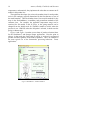
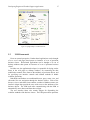
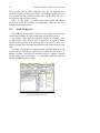
Developing Engineered Product Support Applications
H. James Hoover1, Tony Olekshy2, Garry Froehlich1, and Paul Sorenson1
1
Dept. of Computing Science, University of Alberta, Edmonton, Alberta: 2Avra Software Lab
Inc., Edmonton, Alberta.
Key words:
Product Lines, Application Frameworks, Engineering Applications, Software
Architecture
Abstract:
Product line developers have two primary problems to solve: keeping their
applications relevant to the associated manufactured product line, and evolving
their applications to exploit new information technologies. This paper reports
on our experience in developing commercial applications for engineered
product manufacturers. High quality object-oriented frameworks with good
factoring into services are crucial to addressing both of these issues. We have
also learned that it is not sufficient to develop frameworks that address only
the development of the application. They must also support other parts of the
process: from production of documentation, through help desk integration, to
defect tracking and resolution. This work also contains a catalogue of best
practices and advanced features the we believe will be valuable to other
builders of engineering tools.
1.
INTRODUCTION
During the last five years we developed a number of commercial
applications for manufacturers of engineered products. Our applications
support the marketing and sales activities of manufacturer's main product
line — in this case pressure safety relief valves and booster pumps. These
are not shrink-wrap applications for a generic market, and they are not the
primary product of the manufacturer. The users of the application include the
manufacturer, its distributors, and the product customers. All are experts in
the product domain, but have widely varying levels of expertise in installing
and using software.
1
2
Hoover, Olekshy, Froehlich, and Sorenson
In addition, we developed groupware applications to support the users
and the developers of those applications. This paper reports on the objectoriented framework approach we use, the experience we gained and the
lessons we learned from our successful efforts in engineered product support
using application line technology.
The paper begins by describing what we mean by engineered products
and application line support for these products. We distinguish a product
line (the actual artefacts manufactured) from an application line (the
software applications that support the product line). Section 2 describes in
greater detail the general context for engineered product support that we
discovered and incorporated in our EAF (Engineering Application
Framework). Section 3 elaborates on application workflow, which is one of
the most difficult and important parts of the requirements that must be well
understood for successful engineering product support. Additional
engineering requirements are presented in Section 4. Section 5 provides an
overview of the frameworks we have developed that support the engineering
product requirements identified earlier in the paper. Section 6 describes
some advanced features that we incorporated in our framework as it matured
through many releases using a rapid evolutionary development approach.
We conclude with a recap of the advantages of the application line strategy
we used, and the experiences gained and lessons learned.
2.
ENGINEERED PRODUCT LINES AND PRODUCT
LINE APPLICATION SUPPORT
2.1
Application Domain Background
Avra Software Lab (www.avrasoft.com), working in collaboration with
the Software Engineering Research Laboratory at the University of Alberta,
has developed applications for manufacturers of pressure safety valves and
booster pumps, both of which are good examples of engineered products.
We have developed Internet-based help desk applications to support the
users of the engineered product applications, and created and used
groupware applications that provide planning, scheduling, accounting, and
document repository functions in support of the development of these
applications. Both of these are examples of software used to support the
applications line development for engineered products. We have also
developed multiple instances of these applications using both thick-client
LAN-based technology (which we call the Kalos technology) and thin-client
WEB-based technology (referred to as the Prothos technology).
Developing Engineered Product Support Applications
3
Table 1 categorizes some of the applications by product line domain and
the technology used to build the application. The user's domain for each
application is shown in italics.
Table 1. Application Support Categories
Product Line
Framework Architecture / Technology
Kalos
Prothos
Thick Client / LAN
Thin Client / WEB
Engineered Products
SizeMaster 4
SizeMaster 5
Sprague Pumps
Valves
Valves
Pumps
GroupWare
Task Manager
Help Desk
Café Avra
Software
Valves
Software
SizeMaster is an engineered product application that supports the sizing,
selecting, and ordering of pressure safety relief valves for Farris
Engineering. These valves are used to protect a pressure vessel (such as a
boiler) from exploding in the event that something impairs its normal
operation. Although a simple device, essentially a spring loaded diaphragm
over an orifice, these valves are a canonical example of an engineered
product.
The Sprague Pumps application supports the sizing, selecting, and
ordering of Sprague booster pumps. These pumps use part of the energy in a
pressurized source of fluid to deliver the remainder of the source at higher
output pressure. They are often used to drive high-pressure devices from a
high-volume source of shop air.
In general, the function of these support applications is to bridge the
business and engineering processes and workflows of the product line
manufacturer and their customers. They are also used to support marketing
and sales activities for the manufacturer's product line. For example, they
typically contain the product catalogue, and the customer is not charged for
their use. They are not shrink-wrap applications for a generic market, and
they are not the primary product of the manufacturer.
These applications are essentially database-centric. A database is used to
store the business objects, such as customers, jobs, and orders. A client, run
on the user's desktop, is used to access and manipulate the business objects.
The users of the application include the manufacturer, its distributors, and
its customers. All are experts in the product domain, but they have widely
varying levels of expertise in installing and using software. The applications
must have relatively low cost of learning for a new user, yet be sophisticated
enough to support an expert user in a production setting.
The manufacturers of the engineered products are not software
development organizations, so they have outsourced the development and
support for their applications. Support for these applications is complicated
4
Hoover, Olekshy, Froehlich, and Sorenson
by the fact that product support is done by the manufacturer's engineering
staff, while software support for the application is done by the application
line company (in our case Avra Software Lab).
2.2
Similar Frameworks — Different Technologies
In this development we uncovered a number of important, advanced
features that are common to engineered product support. We incorporated
these into a number of O-O sub-frameworks, which allowed us to share
common architectures, and much of the code, across these applications. Each
sub-framework encapsulates shared code as well as services and hooks for
the application developer that are independent of the implementation
technology. The nature of these services will be discussed further in Section
6.
Two very similar architectures are used to tie the individual subframeworks into an application, loosely "modelled" in Figure 2 and Figure
3.
A Kalos thick-client implementation and a Prothos thin-client
implementation of an application are designed to do more-or-less the same
job. The differences between the frameworks are due principally to the
differences in implementation technology that has occurred with the
adoption of WEB-based computing. Section 5 will describe some of the
components of these architectures in greater detail.
One of the challenges that framework developers face is that changes in
technology can render their framework implementations obsolete. We very
quickly realized that the implementation technology of the framework is less
important than its architecture. It is possible to migrate a good design to a
new technology. In fact we have been using some of the architectural ideas
behind these frameworks for over a decade. The different technologies used
in implementation are shown in Table 2.
Table 2. Framework Technologies
Framework
Kalos Technology
EAF: Engineering
Delphi, embedded
Application Framework
PCS: Product Catalogue
Delphi, embedded
Service
UIM: User Interface
Delphi, Windows
Manager
POM: Persistent Object
Delphi, BDE + SQL
Manager
Prothos Technology
Delphi, server, HTTP
Perl, server, HTTP
Perl, Browser, HTML
Perl, DBI/DBD + SQL
Developing Engineered Product Support Applications
2.3
5
Framework Development Process
Our strategy for building frameworks could be described as continuous
service refactoring in the context of a stable, relatively technology
independent, connecting architecture. That is, the evolving problem
requirements suggest common functionality that can be collected into subframeworks that deliver a specific service. These sub-frameworks attach to
specific points of a very general high-level architecture.
Our efforts to determine the requirements for supporting engineered
products have occurred over the past five years. The original requirements
for SizeMaster 4 were the existing SizeMaster 3, and the manufacturer's
desire to build a new application for the Windows environment. After an
evaluation of the existing application, discussion with the manufacturer's
application line champion, and the usual brainstorming and whiteboard
drawings, the need for and advantages of a general model of this style of
application became apparent.
The common process of sizing, selecting, and ordering was identified and
embellished over time. In particular, we found that the requirements for
these types of applications can be classified along the following lines:
1. Product Specific Requirements: This includes the details of the
particular product line, such as the sizing standards to be followed, the
detailed catalogue information, and any idiosyncrasies in the workflow.
2. Engineering Process Requirements: These are the activities
necessitated by the fact that these applications are being used by
engineers and must support engineering processes, as well as business
processes like quoting and ordering.
3. Generic Application Requirements: These are related to the quality
and flexibility of the application in general, including multi-user
considerations, user interface design, the ability to use various database
systems, testing, support, and so on.
It became clear that the technical requirements for engineering-standards
based calculations were precise, but that the workflow was going to evolve
quickly as we tried to understand how the engineer would use the tool.
Instead of continuing to refine the requirements, we used a rapid
evolutionary approach [McConnell, 1996]. We build the applications
incrementally, with varying degrees of flexibility among their major
components. For example, forms layout and workflow are very flexible.
Although the database schema does not change quite so rapidly, we provide
automatic schema migration. The least flexible is the implementation of the
engineering standards, since restructuring the worksheet introduces
migration issues for existing worksheets, and also necessitates a thorough
review to ensure it is still correct with respect to the standards.
6
Hoover, Olekshy, Froehlich, and Sorenson
The software engineering challenge is to provide the capability to quickly
and accurately generate new applications of this type, and to evolve existing
ones to support their product lines.
One pleasant aspect of this kind of application development is that since
the applications are not the main revenue stream for the manufacturer, they
tend not to be under pressure of creeping features in order to produce a
stream of new revenue generating releases. This is not to say that there isn't a
continuous stream of feature requests, but these tend to be from users and of
the kind that add value to the application.
The next two sections will examine the workflow and engineering
requirements of the engineered product domain that influenced our
framework design.
3.
WORKFLOW REQUIREMENTS
Figure 1 shows the relationship between the user's business processes
and the sizing, selecting, and ordering workflow supported by our
engineered product applications. Each application integrates design tool,
smart catalogue, and order processing. For each product line produced by the
firm, there are one or more applications to support that product line. The
applications are used by both customer and supplier in a way that
interconnects the supplier and customer business processes.
Figure 1. Workflow Model
A common characteristic of engineered products is that they require some
relatively complex decision making, called sizing, prior to being selected and
Developing Engineered Product Support Applications
7
ordered. The term engineered product covers many kinds of manufactured
items, but it can also include services like insurance policies or retirement
plans. The main characteristic of an engineered product is that some
assistance is required in order to decide what particular item to order. For
example, one does not simply order a pressure safety relief valve from a
catalogue. First you must determine your scenario's parameters, such as
working pressures and temperatures, kind of fluid (gas or liquid), amount of
fluid to be relieved and so on, and then using some engineering standard,
such as ASME Section 8, compute the dimensions of the orifice of the value
sufficient to relieve the pressure and protect the vessel.
After sizing comes selection. Given the required size, there will be a
number of candidate products in the catalogue from which one will be
selected (perhaps on the basis of cost). During selection, there are usually a
number of trimming options, such as type of steel, that can be chosen
without affecting the computed size. Sizing and selection can be iterative, in
that decisions made during sizing can affect the range of candidate products
available for selection.
Sets of products are grouped into jobs, so once the products in a job are
selected the entire job can be sent to the supplier for ordering and quoting.
Depending on the result of the quote, the order may be accepted, modified
by the customer, or abandoned.
4.
ENGINEERING REQUIREMENTS
Since these applications are primary used by engineers, we must consider
the demands that are made on our application as a result of engineering
process requirements. That is, what distinguishes an engineering application
from a typical business application such as a spread-sheet or order
processor?
The first thing to recognize is that because engineers are professionally
responsible for their work, they are not a normal application user. Put
bluntly, an engineer should not automatically trust an application. The
application has to earn the confidence of the engineer. How does it do this?
Our approach is to earn the confidence of engineers by building applications
that embody the following principles:
1. Consistency: The user interface and program behaviour must be
consistent for all tools. This is particularly important with respect to the
display and entry of data: how values and their associated units are
displayed, how base units are maintained, and how input and output
changes are brought to the attention of the user.
8
Hoover, Olekshy, Froehlich, and Sorenson
2. Observability: Many applications deliberately hide process state
information from the user and instead guide them through a
predetermined path. Our philosophy is that the user is the best judge of
how to complete the process, and that the tool should ensure that the user
is aware of what has been completed, what remains to be done, and what
effects the current action has.
3. Verifiability: Our applications provide the ability for independent
verification of their behaviour. The entire calculation, both as displayed
and as maintained internally, can be verified by an independent agent.
Unlike most engineering tools, we give the engineer the ability to
perform independent verification using a program of their own design.
4. Auditability: All tools must be able to check their inputs for tampering
or corruption, and produce outputs with the same properties. We want the
same level of certification as a stamped and signed drawing.
5. Extensibility: The application builder cannot anticipate all the possible
application scenarios, so it must be possible for the engineer user to
extend the tool to handle their special situation, while preserving all of
the preceding properties.
So not only does the application need to perform the correct math and
physics, it needs to track revisions and approvals, and generally know who
did what and when in order to support proper engineering process.
Furthermore, new products can be introduced, which can require new
support in the application. Catalogue data can change, which then invalidates
existing installed copies of the application. Engineering standards can
change, which not only invalidates existing installed copies of the
application but also can call into question the sizing of existing installed
products.
Fortunately, new products go through an extensive design and approval
process, and standards tend to change slowly; therefore, existing products do
not change that much. Consequently, we are not faced with the kinds of
radical changes in functionality associated with applications in some other
markets, like software browsers. Our applications tend to evolve via
numerous small incremental changes, via our rapid evolutionary
development process.
5.
APPLICATION FRAMEWORKS
For us, framework technology is a pre-requisite for evolutionary
development. As of this time, we have made roughly 40 releases of
SizeMaster 4. Our goal is to use frameworks to reuse as much of the process
and generic capabilities as possible over the application line. New
Developing Engineered Product Support Applications
9
applications in the line are constructed by using product specific hooks
[Froehlich97, Froehlich99].
The frameworks capture the features common to a broad range of
engineering applications, and can be reused. New applications are made by
attaching the domain specific code of the application to hooks in the
framework. Depending on the particular problem, a new application thus
accounts for 20 to 30 percent of the code, while the remainder is reused from
the framework.
As mentioned earlier, we have two distinct architectures that we
maintain. The Kalos architecture is intended for building desktop-based
thick-clients with a central database. The Prothos architecture is intended
for building browser-based thin-clients that deliver an application over the
web from a central server. The important thing to notice is the structural
similarity between the two architectures. This is primarily due to the fact
that we view an application as a loosely coupled composition of services.
(The role of services in evolution to the web is examined in [Froehlich99b]).
The Kalos and Prothos architecture models shown in Figure 2 and Figure
3 decompose into sub-frameworks as follows. The EAF (Engineering
Application Framework) and the PCS (Product Catalogue Service) are
spatially in the center of the models. The UIM (User Interface Manager) and
POM (Persistent Object Manager) wrap the EAF and PCS services to make
applications out of them.
The user interface consists of the nodes to the left and front of the
models. The user interface forms written by the application developer are
represented by the UI nodes. The UIM framework consists of the UIM
node, which is responsible for marshalling the nodes below it (which contain
the classes that implement the actual user interface components and
widgets).
Persistent objects are handled by nodes to the back and right of the
models. The business classes written by the application developer are
represented by the BC nodes. The POM framework consists of the POM
node, which provides an abstract base class for the business classes, and a
singleton for managing the working set of business objects. The POM is
responsible for invoking the services of the nodes below it (which contain
the classes that implement our actual OORDBMS via SQL).
10
Hoover, Olekshy, Froehlich, and Sorenson
Figure 2. Kalos Framework Architecture Model
Figure 3. Prothos Framework Architecture Model
Developing Engineered Product Support Applications
11
The application itself is represented by the large node at the top of the
models. With Kalos, the application is conceptually a set of menus that
dispatch instances of UI form classes. With Prothos, the application is
conceptually a set of URLs that encode instances of the UI page classes. In
Kalos, the UIM manages the application frame and menus, dispatches new
UI instances, and manages the set of concurrently active UI instances. In
Prothos, the UIM is the HTTP daemon that serves the application, which
converts the requests for URLs representing UI instances into HTML
responses for the client. In both cases, the UI classes are responsible for
selecting and manipulating instances of business classes, which in turn are
made persistent by the POM.
The edges in the architecture models represent inter-service
communication, which the application developer sees as API methods. In
Prothos, inter-service communication is physically implemented via
internetworking channels, so the services can be provided by multiple
processors and the user interface can be physically de-coupled from the local
context of the service providers. In Kalos, the communication between the
services is constrained to a single processor (or two, when the database is
controlled by a separate server).
Viewed statically, the architectural models show the relationships
between the classes in the frameworks. Viewed dynamically, they show the
interactions between the objects accessed by users at run time and the
services that manipulate those objects.
Frameworks have many benefits, the two most important being that
features are implemented consistently across applications, and that the time
to construct the application is dramatically reduced. From an application line
perspective, the code in the framework is less important than the architecture
it embodies. For example, in implementing the web delivered SizeMaster 5,
we replaced the entire Kalos thick-client code base, but used essentially the
same architecture.
Engineering applications are notoriously difficult to fully specify,
primarily because the presence of a tool enables the engineer to do more in
new ways, and this affects their perception of the problem they wish to
solve. Our framework technology enables us to rapidly produce a series of
prototypes that evolve along with the client's understanding of the problem
that they wish to solve. This approach works well with the dynamic nature of
engineering applications.
5.1
EAF Framework
The Engineering Application Framework is used to build engineering
worksheets. Each worksheet is a collection of data elements and calculations
12
Hoover, Olekshy, Froehlich, and Sorenson
that represent the contents of an engineering code or standard. Each
engineering application that we build has one or more worksheets that
capture the product-specific engineering calculations of the application.
Sizing interacts primarily with the worksheets. The user interface of the
application, provided by another framework, navigates through the
worksheet but does not do any engineering computations. In this way we
keep the robust core engineering part of an application relatively isolated
from the more fragile user interface.
Many engineering calculations are organized around the concept of a
worksheet and therefore we incorporated it as a key concept in our
framework. The worksheet guides the engineer through the calculations,
reminding them of important steps, ensuring that key decisions and subcalculations are made in the proper order, and recording the process for
future review. Having performed and verified the calculation, the engineer
then signs the worksheet and it becomes part of the permanent design
documentation of the project.
A worksheet is a hierarchically organized collection of interdependent
calculations. Each calculation can be thought of as a black box. The box has
a set of inputs from other calculations, a set of outputs which go to other
calculations, some local data which is its state, and some external settings
taken from the outside world. Each calculation is given a type.
Each calculation performs some operations on its inputs, externals, and
locals, and produces some outputs. Calculations are structured so that they
cannot alter their inputs or externals. Locals can be read and modified, and
outputs can only be modified, not read. Furthermore, only one calculation
can change the value of an output, thus ensuring that values can be traced
back to their origins. Figure 4 shows a screen shot view of a subcalculation
in the SizeMaster 4 worksheet.
Unless the user is familiar with the worksheet, they will normally need
guidance as they navigate through it. This guidance is provided through
scenario wizards. A scenario wizard sits "above" the calculation, with links
hanging down to the locals and externals needed for its particular scenario,
as in Figure 5 below.
Developing Engineered Product Support Applications
Figure 4. Worksheet View
Figure 5. Workflow Wizards
13
14
Hoover, Olekshy, Froehlich, and Sorenson
Figure 6. SizeMaster 4 - Workflow Wizard
Figure 7. SizeMaster 5 - Workflow Wizard
Developing Engineered Product Support Applications
15
The wizards in Figure 6 and Figure 7 take the user through the workflow
involved in computing the orifice area for a scenario in which the flow out of
a pressure vessel is blocked for some reason. Note the similarity between
the Kalos-based and Prothos-based versions. The underlying calculation and
workflows are identical, only the view has changed. This is an example of
using frameworks to preserve behaviour across technologies.
5.2
PCS Framework
The product catalogue service determines, for a given engineering
worksheet, the recommended products from each series of models in the
manufacturer's catalogue that are suitable for the given engineering scenario.
In addition, given any model number from the catalogue, the catalogue
service can determine whether or not the model is suitable for the given
scenario.
The model numbers for engineered products can be quite complex, such
as 26MA10-120/S3 or S-216-JD-34-SS, because they encode all the details
needed to completely select a single engineered product from the
manufacturer's product line. The relationship between model numbers and
the engineering worksheet is also complex, because changing a single option
in the model number can create exceptions to the normal candidate selection
process, depending on the values of the variables in the worksheet.
Rather than maintain a complete list of all possible model numbers,
which in many cases would be prohibitively large, the PCS uses the
following information and a set of rules to determine the complete list of
model numbers.
1. A table specifying how to parse model numbers into their fields.
2. A table specifying the valid values for each field of the model number.
3. A table specifying valid base model numbers, which are usually the first
few characters of the model number. This table contains the key
selection parameters for each base model, such the range of pressures and
temperatures for which the product can be considered a candidate for
selection.
4. A table specifying how the values of model number fields affect the
default materials used for the parts of the product.
The PCS provides an abstract base class upon which the application
developer bases the model number class. The application developer
implements abstract methods, for the base class, that provide the common
find-candidates, is-candidate, and get-attribute methods for the product line.
These methods use the tables described above to find appropriate pressures,
16
Hoover, Olekshy, Froehlich, and Sorenson
temperatures, and materials; they implement the rules that are common to all
models in the product line.
The application developer also writes a descendent class for each product
series in the catalogue (typically determined by the first character or two of
the model number). These descendent classes can override methods for key
steps in the find-candidates, is-candidate, and get-attribute methods of the
common class. For example, the applicable temperature range can be
restricted for /S4 models in the 26 series, or the spring material can be
changed from the default steel for 55AB99-4 models to nickel when the
pressure is over 1200 PSI, unless the /M option is selected, in which case the
spring is chrome-moly.
Figure 8 and Figure 9 contains screen shots of product selection forms
for the SizeMaster 5 and Sprague Pumps applications. Here the point to
observe is that much the same kind of activity is involved in engineered
product selection regardless of the kinds of products. This is an example of
the more typical use of the frameworks preserving behaviour across
applications.
Figure 8. SizeMaster 5 - Product Selection
Developing Engineered Product Support Applications
17
Figure 9. Sprague Pumps - Product Selection
5.3
UIM Framework
From an external perspective, Prothos-based applications can be thought
of as a set of web pages that operate on instances of a set of persistent
business classes. Kalos-based applications can be thought of as set of
desktop windows that operate on instances of a set of persistent business
classes.
In either case, the application developer is responsible for laying out the
forms in the web pages or desktop windows, for connecting the data
modification controls in the forms to the attributes of persistent objects, and
for specifying user interface controls and callback methods to handle
workflow operations.
Both Kalos and Prothos use a traditional browse, query, zoom, view, and
edit model for user navigation through the business classes. Each of the
browser, viewer, and editor forms contains a number of database-aware user
interface widgets that provide the users with access to the attributes of the
business objects. The UIM looks after communicating with the POM to
automatically move data to and from these widgets.
The user interface forms also contain widgets for dispatching the
workflow methods of the business classes. The UIM passes these operations
18
Hoover, Olekshy, Froehlich, and Sorenson
to the business objects, which implement the rules for modifying their
persistent attributes to effect the operation. The UIM then updates the user's
view to show the new persistent attribute values, which causes the user to
see the result of the selected operation.
Figure 10 and Figure 11 contain screen shots of the master/detail
browse/view forms for an instance of a SizeMaster 4 Job class, and for a
Sprague Pumps orders browser.
5.4
POM Framework
The POM provides the abstract base class for an application's business
classes, and it manages the set of concurrently active business objects.
The business classes represent traditional entities like customer, order,
tag, and product. Each business class is defined by an extended schema
(describing the properties of the persistent objects in the class) and a set of
business methods that implement the domain-specific business rules for the
class.
The POM is responsible for managing login controlled database access
sessions and for assuring the consistency of concurrent transactions. It
handles roll-back, roll-forward, referential integrity, database rebuilds,
schema conversions, and backups. It co-ordinates interaction with the
underlying RDBMS engine via SQL.
Figure 10. SizeMaster 4 Job View
Developing Engineered Product Support Applications
19
Figure 11. Sprague Orders Browser
6.
CATALOGUE OF ADVANCED FEATURES
Application quality is the result of attention to many details. This section
is a catalogue of some of the important features or best practices that in our
experience lead to a quality engineering application. Our intent is that the
experienced application developer should identify with many of these, and
find some novel ones.
The external interfaces to the applications are deliberately chosen to
exploit the experiences of the typical user of Windows-based and Browserbased applications. The crucial application line details are behind the scenes
and not visible, or appreciated, by the casual user. In this section we examine
how we support these aspects of the application.
Since these features are relatively consistent between applications in the
application line, we have incorporated them into our application frameworks.
Depending on the nature of the feature, it is either incorporated directly in
the framework as a hook, or the feature is generic enough to be incorporated
into the framework.
For the purposes of this section, we have divided the advanced features
into these general categories.
1. Core Features of interest to any application in almost any domain. Many
of these features are geared to making problem diagnosis easier for
developers and the help desk.
20
Hoover, Olekshy, Froehlich, and Sorenson
2. Engineering Features of interest to applications that need to support
engineering process
3. Persistence Features of interest to any application that stores its
business objects in a database.
6.1
Core Features
6.1.1
Trouble Stack
In our experience, the single most important facility in an application is
the trouble stack. As exceptions are generated, explanatory messages are
pushed onto the trouble stack. For example, an attempt to grab a write lock
on a record might fail because the record has been updated by someone else.
The failure generates an exception with message "database changed by
someone else". The code attempting to obtain the write lock can catch the
exception, stack the message "can't save changes to database" and continue
unwinding. Similarly the top level code attempting to post the transaction
could stack the message "can't send order to quoting".
Unwinding the trouble stack provides an explanatory narrative for both
the user and the developers. For example: "Can't send order to quoting
because can't save changes to database because database changed by
someone else." The trouble stack output window has a copy to clipboard
feature that can be used to email the entire stack trace to the help desk. Since
all our messages are uniquely numbered with a code that is easy to search for
in the source, we can quickly determine where the application was when the
failure occurred.
6.1.2
Data Signatures
We compute MD5 checksums on all configuration and crucial data files
in order to detect tampering or corruption. For example SizeMaster will not
start if the valve catalogue data is incorrectly signed. As evidence of its
practicality, we note that when introduced, this feature caught a few cases
where experienced users were altering the data files in order to handle
situations not yet built into the tool. Knowing that the configuration data and
database files have a high probability of being consistent saves substantial
diagnostic time.
Developing Engineered Product Support Applications
6.1.3
21
Configuration Report
This report indicates the state of the particular installation, such as the
characteristics of the machine, the directory the application is installed in,
and where the database middle-ware is located and what version it is.
6.1.4
HTML-based Reports and Displays
We made an early decision to use HTML for all reports and 2D text
layouts on forms. The constraint-based layout of HTML simplifies the
resizing of forms. We employ a subset of HTML, with our own browser (a
source-licensed component from a supplier) that we modified to have page
breaking and numbering, and a facility for rendering equations. Reports can
be emailed to users without the enhanced viewer using the MIME
encapsulation standard for multi-part forms.
6.1.5
Apalon markup language
Instead of working in raw HTML we use our own markup language,
implemented in Perl, that enables us to abstract out the picky details of
HTML and work with larger structural components. It also permits us to
integrate various application components, for example the same document
that describes a formula panel on a form also generates an entry in the
master document of all formulas, and generates the image bitmaps necessary
for emailing any report containing that formula. Furthermore, using Apalon
de-couples us from HTML, in the sense that we could write translators to
generate other languages such as LaTeX and rich text format.
6.1.6
Handbook Writer's Assistance
To make the user manual writer's job easier, the application has a built-in
screen capture facility. This not only captures a screen image (in two
resolutions, one for display and one for printing), it also generates the
Apalon markups for each of the widgets on the form so that hot spot links
can be embedded into the manual.
6.2
Engineering Features
6.2.1
Worksheet Navigation
A worksheet is a complicated object. Although hierarchically structured,
the dependencies between data items in the worksheet can thread across the
22
Hoover, Olekshy, Froehlich, and Sorenson
hierarchy. A frequent question asked by users is "how is this value
computed?" To facilitate navigating through a worksheet, double clicking
on any value anywhere in the application takes you to the calculation in the
worksheet responsible for computing the value (as shown in Figure 4).
Within the actual worksheet, a stack is used when following these links so
that one can go back to the calculations being previously examined. The
formulas being computed are displayed on the worksheet. The user can also
view the actual Object Pascal code associated with the formula. In a few
cases, users have employed this feature to uncover a discrepancy between
what was actually computed and what was being claimed.
6.2.2
Basis and Display Units
Units of measurement are crucial to engineering calculations. Each
numeric data element in a worksheet has a particular category, such as
length. Within the category each data element has a fixed basis units, such
as feet. Basis units are chosen to be the same as the engineering standard
implemented in the worksheet. All computations are done in basis units.
Associated with each data element is its user selectable display style, which
is used to specify the way the value is displayed, for example display and
input in meters, even though the calculation is in feet. All conversions to
and from basis units are done by the framework. The worksheet designer
can ignore the issue completely. The framework also enforces consistency
of displayed units. If a particular piece of data, say vessel height, is in feet
on one form, it will be in feet on all other forms and reports.
All data elements have the possible value of "undefined" which is distinct
from other possible values that the element can have. Any attempt to
compute with an undefined value raises an exception and prevents further
computation that depends on that data.
6.2.3
Special Input Widgets
A common engineering practice is to tweak a parameter slightly. We
have the current value displayed while the new input is entered into a drop
down part of the control. This rectifies the annoying behaviour of standard
data controls in which the current value vanishes when input is begun.
These widgets also distinguish between values entered by the user
directly, and values obtained from the pick list associated with the widget.
For example, in a numeric field specifying the specific gravity of a liquid,
the field will distinguish between a 1.0 entered in by the user, and a 1.0
entered as a result of picking Water from the pick list. It is important in
trouble diagnosis to know where the 1.0 came from.
Developing Engineered Product Support Applications
6.2.4
23
Check Worksheets
In the event that a defect in the application is discovered, or the
engineering standard changes, it is important that it be easy to check if this
affects any prior sizing calculations. This feature checks each of the
worksheets against the new release and flags any critical differences. This is
another argument for keeping business objects in a properly managed
database.
6.2.5
Worksheet Version Migration
The worksheets can also change as a result of evolution in the tool as new
capabilities are added. Each worksheet has a version number, and changes
are classified as minor or major. A minor change means that existing
worksheets are upwardly compatible. A major change means that handcrafted migration code needs to be written.
6.2.6
External Testing Hooks
We can generate a version of SizeMaster that has the UI disabled and
communicates via sockets, thus acting as worksheet server. This enables us
to do regression tests on the core worksheet directly, without having to use
UI based test harnesses.
6.2.7
Database Access Keys
Since these application contain engineering standards and catalogue data
that can change over time, it is important that stale versions not persist once
distributed. Built in to each release is a database access key that must be
periodically updated through the help desk. When this key expires, the
application will fail to start. This is of course also important when defects in
the application are discovered.
With this feature we can be confident that all legitimately obtained
versions will eventually expire and users will be required to contact the help
desk to keep their application up to date. The help desk user roster, its batch
mailings, and its use for software distribution makes this possible.
24
Hoover, Olekshy, Froehlich, and Sorenson
6.3
Persistence Features
6.3.1
Object Model, Object Ids, and Foreign Keys
Our persistent object manager uses a traditional mapping of classes into
tables, objects into records, and attributes into fields. Every object is
identified by a unique object id field. All foreign keys are the ids of their
referent objects. The persistent object base class knows how to automatically
retrieve the target object when the value of a foreign key field is retrieved.
You can even de-reference null foreign keys, and the persistent object
manager knows to return null results for the attributes of those non-existent
objects.
6.3.2
Concurrent Transaction Consistency
Every persistent object has a write count attribute that is incremented,
under lock, whenever the object is written to the database. The persistent
object manager refuses to update records if their write count at update time
does not match the write count as last read from the database. Since all write
counts are checked together, under lock, when a transaction commits and
before any writing is done, the existence of any optimistic lock failure
effects a rollback of the entire transaction.
The UIM hooks into the POM to automatically maintain the last-read
write-lock counts for each business object being accessed by the application,
even though in the case of Web-based applications this requires shipping the
write-lock count out to the browser and back, and checking that it hasn't
been tampered with on the client side. The application developer is
completely freed from locking considerations.
6.3.3
Referential Integrity
The persistent object manager knows how to maintain an inverted index
connecting all object ids used as foreign keys back to their referrer objects.
Using this index, the POM refuses to delete records that have any foreign
key pointing to them, thus ensuring the referential integrity of the database.
Referential integrity checks are performed during transaction commit, under
lock, so a violation has the effect of rolling back the entire transaction.
6.3.4
Journaling, Roll-Forward, and Revision Control
In Kalos-based applications, record keeping for revision control was the
responsibility of the application developer. We are currently in the process
Developing Engineered Product Support Applications
25
of extending the Prothos persistent object manager to journal all database
adds, write, and deletes. This journal can be used by the application
developer to produce any domain-specific change reports required by the
user.
In addition, since Prothos is already internetwork-aware, we can copy the
journal entries to one or more physically remote logging servers, via TCP/IP,
in real time. This means that in the event the application server disappears in
a puff of smoke, we can simply install the most recent CD-ROM backup on
a new machine, play forward the journal from a remote site, and reconstitute
the database as of the last successfully completed transaction.
6.3.5
Replication
The persistent object manager can maintain unique object ids across
databases, not just within them. It does this by pre-pending a unique
database id to each object id. In addition, each object has a writeable-by
attribute, which contains the id of the database within which the object can
be updated.
Application developers can use this facility to implement a simple
replication facility. An XML-encoded stream containing, for example, an
order and all its detail items, can be exported from one database into other
databases. If the writeable-by attributes in the XML stream are left set to the
exporting database id, then all importers effectively receive read-only copies
of the data. If the writeable-by attributes in the XML stream are set to a
target database's id, then that database will receive a writeable copy of the
data, the exporter will be left with read-only access, and any other importers
will still receive a read-only copy.
This persistent write lock facility can be difficult to manage, because of
the need to handle a lost XML stream without violating the universal onewriter-only rule, and because of the need to handle foreign keys that may not
be in the importer's database. However, we have successfully used it to move
orders for engineered products from a central database, to a laptop for
modification while not connected to the central database, and then back to
the central database when the laptop user has completed their work.
6.3.6
Schema Conversions
The persistent object manager includes a mechanism for handing schema
migration. The POM includes a base class that handles copying records from
a database with an old schema to one with the new schema. This class can
automatically handle simple field name and type conversions, and its
methods can be overridden on a per-class basis to handle more complex
26
Hoover, Olekshy, Froehlich, and Sorenson
conversions. When the POM notices that a database is marked with as
having an obsolete schema, the user can simply pick the conversion tool and
all changes required to bring the database up to date are applied.
6.4
Remarks
The many features just discussed have been incorporated into our
frameworks as they evolved through several versions. This would not have
been possible without a well-defined basic architecture, which we were
fortunate enough to have and take the time to develop at the very beginning.
7.
RELATED WORK
While software companies have been doing product line development for
many years, it is only recently that the issues of building, evolving and
deploying frameworks, processes and tools in support of product lines have
been researched. Some of the most advanced work is Batory’s GenVoca
Model [Batory97] and Jakarta Tool Suite (JTS) for implementing GenVoca
product-line architectures. Software reuse in general [Jacobsen97], and
frameworks [Johnson92, Fayad97] and components-oriented development
[Bosch97] in particular, are important approaches for achieving the largescale design and code reuse that is desirable in product-line development.
Our work on hooks [Froehlich99a] and Pree’s work on hotspots [Pree95]
focus on the prescriptive documentation of frameworks which, we believe, is
fundamental to the production of quick-to-market, high-quality product line
software.
8.
CONCLUSIONS
Application line developers have two primary problems to solve: keeping
their applications relevant to the associated manufactured product line, and
evolving their applications to exploit new information technologies.
Our experience has convinced us that high quality object-oriented
frameworks with good factoring into services are crucial to addressing both
of these issues. Although the implementation of a framework is important, it
is more important that it have a good architecture. Our framework
architectures have survived the transition from the world of thick clients and
database to the arrival of the web as the in-vogue delivery mechanism.
The ability to do rapid evolutionary development must be part of the
framework infrastructure. The judicious factoring of services into a number
Developing Engineered Product Support Applications
27
of collaborating frameworks enables us to manage differing rates of change
corresponding to the level of uncertainty in the application requirements.
User interface and workflow are the most flexible, data model changes less
so, and engineering worksheet changes are tightly controlled.
We have also learned that it is not sufficient to develop frameworks that
address only the development of the application. They must also support
other parts of the process: from production of documentation, through help
desk integration, to defect tracking and resolution.
Finally, within the engineered-product domain, we are confident that we
have a good working set of best practices and advanced features that are
embodied in our techniques for building and supporting applications. In this
paper, we have shared our experiences and development strategy in the hope
that it will be of value to other builders of engineering tools.
ACKNOWLEDGEMENTS
We wish to gratefully acknowledge research support from the Natural
Sciences and Engineering Research Council of Canada, in particular the
Industrial Oriented Research program; the National Research Council of
Canada and its IRAP program; Farris Engineering and Josh Kolenc, the
driving force behind SizeMaster; and especially the many engineers around
the world who use our software and give us feedback.
REFERENCES
[Batory97] Composition Validation and Subjectivity in GenVoca Generators, IEEE
Transactions on Software Engineering (special issue on Software Reuse), February 1997,
67-82
[Bosch97] J. Bosch, Adapting Object-Oriented Components, Proceedings of the 2nd
International Workshop on Component Oriented Programming (WCOP’97), Jyväskylä,
Finland, 13-22.
[Froehlich97] G. Froehlich, H. J. Hoover, L. Liu, P. Sorenson. Hooking into Object-Oriented
Frameworks. In Proceedings of the 1997 International Conference on Software
Engineering (Boston, Mass.,1997), 491-501.
[Froehlich99] G. Froehlich, H. J. Hoover, P. Sorenson. Realizing Requirements in ProductLine Development using O-O Frameworks. Australian Journal of Information Systems,
Special Issue on Requirements Engineering, pp 6-12, 1999.
[Froehlich99a] G. Froehlich, H.J. Hoover, L. Liu and P. Sorenson. Reusing Hooks. In
Building Application Frameworks. M. Fayad, D. Schmidt and R. Johnson, ed. Wiley
Computer Publishing, New York. 1999, 219-235.
[Froehlich99b] G. Froehlich, H.J. Hoover, Wendy Liew and P. Sorenson. Application
Framework Issues When Evolving Business Applications for Electronic Commerce.
Information Systems, Vol 24 No 6, Sept 1999, 457-473.
28
Hoover, Olekshy, Froehlich, and Sorenson
[Jacobson97] I. Jacobson, M. Griss, and P. Jonsson. Software Reuse: Architecture, Process
and Organization for Business Success, Addison-Wesley, 1997.
[Johnson92] R. Johnson, Documenting Frameworks Using Patterns, Proceedings of
OOPSLA’92, Vancouver, Canada, 1992, 63-76.
[McConnell96] S. McConnell, Rapid Development, Microsoft Press, Redmond Washington,
1996.
[Pree95] W. Pree, Design Patterns for Object-Oriented Software Development. AddisonWesley Publishing Company, Reading, MA. 1995.
[Robertson93] S. Robertson and K. Strunch. Reusing the Products of Analysis. Proceedings
of the Second International Workshop on Software Reusability. (Lucca, Italy, March
1993).