1
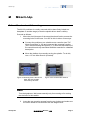
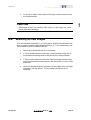
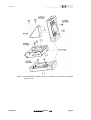
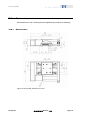
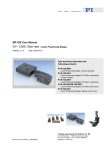
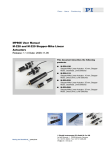
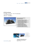
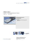
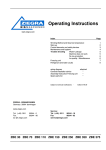
MP61E User Manual
M-122 Micro Translation Stage
Release: 1.0.0 Datum: 01.08.2007
This document describes the following
product:
■
M-122.2DD
High-Precision Micro Translation Stage with
linear encoder
© Physik Instrumente (PI) GmbH & Co. KG
Auf der Römerstr. 1 ⋅ 76228 Karlsruhe, Germany
Tel. +49 721 4846-0 ⋅ Fax: +49 721 4846-299
[email protected] ⋅ www.pi.ws
Physik Instrumente (PI) GmbH & Co. KG is the owner of the following company names and trademarks:
PI®
The following designations are protected company names or registered trademarks of third parties:
LabVIEW
Copyright 1999–2007 by Physik Instrumente (PI) GmbH & Co. KG, Karlsruhe, Germany.
The text, photographs and drawings in this manual enjoy copyright protection. With regard thereto, Physik
Instrumente (PI) GmbH & Co. KG reserves all rights. Use of said text, photographs and drawings is
permitted only in part and only upon citation of the source.
Erstdruck 01.08.2007
Document Number MP61E BSc, Release 1.0.0
M122_User_MP61E.doc
Subject to change without notice. This manual is superseded by any new release. The newest release is
available for download at www.pi.ws. (http://www.pi.ws) zum Herunterladen verfügbar.
Declaration of
Conformity
according to ISO / IEC Guide 22 and EN 45014
Manufacturer:
Physik Instrumente (PI)
GmbH & Co. KG
Manufacturer´s
Address:
Auf der Römerstrasse 1
D-76228 Karlsruhe,
Germany
The manufacturer hereby declares that the product
Product Name:
Translation Stage
Model Numbers:
M-122
Product Options:
all
complies with the following European directives:
73/23/EWG, Niederspannungsrichtlinie / 73/23/EEC, Low voltage directive
89/336/EWG, EMV- Richtlinie / 89/336/EEC, EMC-Directive
98/37/EG, Maschinenrichtlinie / 98/37/EC, Machinery Directive
The applied standards certifying the conformity are listed below.
Electromagnetic Emission:
EN 61000-6-3, EN 55011
Electromagnetic Immunity:
EN 61000-6-1
Safety (Low Voltage Directive):
EN 61010-1
Safety of Machinery:
EN 12100
July 31, 2007
Karlsruhe, Germany
Dr. Karl Spanner
President
About this Document
Users of this Manual
This manual is designed to help the reader to install and operate the M-122 Micro Translation Stage. It
assumes that the reader has a fundamental understanding of motion control concepts and applicable
safety procedures.
The manual describes the physical specifications and dimensions of the M-122 Micro Translation Stage
as well as the procedures which are required to put the associated motion system into operation.
Conventions
The notes and symbols used in this manual have the following meanings:
WARNING
Calls attention to a procedure, practice or condition which, if not
correctly performed or adhered to, could result in injury or death.
CAUTION
Calls attention to a procedure, practice, or condition which, if not
correctly performed or adhered to, could result in damage to equipment.
NOTE
Provides additional information or application hints.
The motion controller and the software tools which might be mentioned in this documentation are
described in their own manuals. Current releases can be downloaded from the PI Website as PDF files
(www.pi.ws (http://www.pi.ws)). For updated releases contact your Physik Instrumente sales engineer or
write an email [email protected] (mailto:[email protected]).
!
Contents
1
Introduction
1.1
1.2
1.3
1.4
1.5
2
3
Product Description............................................................................. 3
Prescribed Use.................................................................................... 4
Safety Instructions............................................................................... 4
Unpacking ........................................................................................... 5
Accessories......................................................................................... 6
Start-Up
2.1
2.2
2.3
7
Mechanical Mounting .......................................................................... 7
Stacking M-122 stages........................................................................ 8
Interconnecting the System............................................................... 10
Operational Considerations
3.1
3.2
3.3
3.4
3.5
3
12
Linear Encoder.................................................................................. 12
Limit Switches ................................................................................... 12
Reference Switch .............................................................................. 13
Motor Controllers............................................................................... 13
Host PC............................................................................................. 13
4
Maintenance
14
5
Troubleshooting
15
5.1
5.2
Troubleshooting ................................................................................ 15
Customer Service.............................................................................. 16
6
Old Equipment Disposal
17
7
Technical Data
18
7.1
7.2
Specifications .................................................................................... 18
Dimensions ....................................................................................... 19
7.2.1
7.2.2
7.3
Dimensions ......................................................................................... 19
Angle Bracket and Adapter Plate ....................................................... 20
Pin Assignments ............................................................................... 21
7.3.1
Analog DC-Motor Versions................................................................. 21
8
DC Motor Controllers
22
9
Glossary of Terms
25
10
Index
27
Introduction
1
Introduction
1.1
Product Description
Figure 1: M-122.2DD micro translation stage (golf ball for size comparison)
The M-122 palm-top-sized translation stage combines small dimensions,
high speeds and very high accuracy at a competitive price. It features a
space-saving, folded drive train with the servo motor and drive screw
side-by-side. Equipped with a non-contacting optical linear encoder and a
preloaded, precision-ground, ball screw, these stages can provide much
higher accuracy and better repeatability than conventional stepper motor
stages or rotary encoder-equipped servo motor stages.
Low Friction, High Speed, Maintenance-Free
Due to its low-friction, the backlash-free ball screw yields significantly higher
mechanical efficiency than leadscrews, and allows maintenance-free, high
duty-cycle operation at high velocities up to 20 mm/sec.
XY and XYZ Combinations
M-122 stages can be combined to very compact XY and XYZ systems. The
M-122.AP1 mounting bracket is available to mount the Z-axis.
www.pi.ws
M-122 MP61E Release 1.0.0
Page 3
Introduction
1.2
Prescribed Use
Correct operation of the M-122 positioners is only possible in combination
with a suitable controller/driver (ordered separately) and software.
The controlling device must be able to read out and process the signals from
reference and limit switches and the incremental position encoder to ensure
proper performance of the servo-control system.
Based on their design and realization, the M-122 stages are intended for
single-axis positioning, adjusting and shifting of loads at various velocities.
M-122 positioners can be mounted horizontically or vertically. To achieve the
specified guiding accuracy, the positioners have to be mounted on a flat
surface to avoid torsion of the basic profile.
The positioners may only be used for applications suitably in accordance
with the device specifications.
Respect the safety instructions given in this User Manual. The operator is
responsible for the correct installation and operation of the M-122.
The verification of the technical specifications by the manufacturer does not
imply the validation of complete applications. In fact the operator is
responsible for the process validation and the appropriate releases.
The M-122 meets the specifications as defined by DIN EN 61010 for safe
operation under normal ambient conditions. See the specifications table for
details (see "Specifications" p. 18).
1.3
Safety Instructions
Read carefully the User Manuals of all other components involved such as
controllers or software.
Read the following before operating the equipment covered in this manual:
CAUTION
Read this before operating the equipment covered in this manual.
Always keep the User Manual safe and close to the described device. In
case of loss or damage to the instructions, please order a new copy from
your PI distributor or download one from www.pi.ws (http://www.pi.ws).
Also keep and add all further information (e.g. extended instructions or
Technical Notes) to the User Manual.
www.pi.ws
M-122 MP61E Release 1.0.0
Page 4
!
Introduction
WARNING—CRUSH HAZARD
Never put anything where the moving platform or any connected object
could possibly trap it! The moving platform can accelerate rapidly and
generate high forces which can cause damage or injury.
WARNING
M-122 stages are powered by powerful electric motors and can
accelerate to high speeds. Be aware that automatic limit switch halt may
not be supported by, or activated at the motor control electronics.
Be aware that failure of the motor controller may drive the mechanics
into a hard stop at high speeds.
When the mechanics is first connected to the motor controller, be aware
that it could start an undesired move.
!
CAUTION
1.4
Unpacking
Crashes can cause irreparable damage. Do not disable limit switches in
software. Test limit switch operation at low speeds. Stop system if
necessary. Do not let it run against a hard stop.
Unpack the M-122 Micro Translation Stage with care. Compare the contents
against the items covered by the contract and against the packing list.
The following components are included:
■
M-122 Micro Translation Stage
■
C-815.38 motor cable for connecting to motor controller
■
000018146 screw set
■
MP61E User Manual for M-122 in printed form (this document)
Inspect the contents for signs of damage. If parts are missing or you notice
signs of damage, contact PI immediately.
www.pi.ws
M-122 MP61E Release 1.0.0
Page 5
Introduction
Save all packing materials in case the product need be shipped again.
1.5
Accessories
The following accessories (see "Angle Bracket and Adapter Plate" p. 20) can
be ordered for use with the M-122 Micro Translation Stage:
■ M-110.01: Adapter plate for mount of M-122 stages on honeycomb
tables (metric and inch), M-400 and M-500 translation stages and
rotation stages
■
M-122.AP1: Angle bracket for vertical mounting of M-122 stages
Contact your PI represenstative or write [email protected] if you need additional
components.
www.pi.ws
M-122 MP61E Release 1.0.0
Page 6
Start-Up
2
Start-Up
2.1
Mechanical Mounting
The M-122 positioner is usually mounted with its base firmly bolted to a
baseplate or another stage (so that the spindle-driven sled is visible).
Proceed as follows:
1 Move the sled (blue part of the stage) back and forth to access the
mounting holes in the base. You can do this in either of two ways:
■
Connect the positioner to a suitable motor controller (see "DC
Motor Controllers" p. 22) and command the necessary motion
(see "Interconnecting the System" p. 9). See the User Manual of
the controller and any associated software manuals for a detailed
description.
■
Move the platform by manually turning the spindle. To do this,
use a 1.5 mm Allen wrench (included).
Figure 2: Mounting hole in the M-122
base; left hole partially
obscured by the sled
Figure 3: M-122 with Allen wrench
Note
Turn the leadscrew / ball screw manually only for mounting or for moving
the sled off of a limit switch.
2
www.pi.ws
Insert the two mounting screws form the top; tighten and make sure
the screw heads do not interfere with the stage motion.
M-122 MP61E Release 1.0.0
Page 7
Start-Up
3
To mount an object on the sled of the stage, use M3 screws in the
six threaded holes.
CAUTION
Overlength screws will interfere with motion of the stage and could
cause permanent damage!
2.2
Stacking M-122 stages
You can assemble stacked XY- or XYZ-systems with M-122 positioners. Be
sure to read the chapter "Mechanical Mounting" (p. 7). For assembling, use
the included screws. Proceed as follows:
www.pi.ws
1
Attach the X-axis positioner to its mounting.
2
If Y-axis motion desired, mount the Y-axis positioner using two of
the threaded mounting holes in the sled of the X-axis positioner.
3
If Z-axis motion desired, mount the Z-axis mounting bracket using
two of the threaded mounting holes in the sled of the X- or the Y-axis
positioner.
4
When the bracket is affixed, attach the Z-axis stage to it in the right
orientation (see fig. below). The moveable bearing has to be
upturned.
M-122 MP61E Release 1.0.0
Page 8
!
Start-Up
Figure 4: Assembling M-122 stages to form an XYZ-system, maximum screw length
is given in mm
www.pi.ws
M-122 MP61E Release 1.0.0
Page 9
Start-Up
2.3
Interconnecting the System
WARNING—CRUSH HAZARD
Never put anything where the moving platform or any connected object
could possibly trap it! The moving platform can accelerate rapidly and
generate high forces which can cause damage or injury.
Figure 5: M-122-2DD: positive direction of motion
Prior to operation, you should read the documentation for your motor
controller.
To operate a stage, proceed as follows:
www.pi.ws
1
Install/connect the controller following the instructions in the
controller manual. If you are going to use a host computer, install the
host software in the host computer. This procedure is described in
the controller User Manual and/or associated software manuals.
2
Connect the positioner to the controller using the connecting cable
(part number C-815.38). With multi-axis controllers, be sure to note
the axis designation of the connection selected.
3
Use the software to adopt the controller to the stage.
4
Command a few test moves to make sure everything is working
properly.
M-122 MP61E Release 1.0.0
Page 10
Start-Up
For best performance and system compatibility we recommend using PI
controllers. This User Manual includes a list of suitable controllers (see "DC
Motor Controllers" p. 22).
Most PI controllers come with a graphic-user-interface-software which is
easy to setup and allows quick installation and testing.
NOTE
Most standard motor controllers and / or software from PI use a
database which contains information on all standard micropositioners
and installs automatically with the host software. This database, a file
called pistages.dat, also includes an initial set of PID servo-control
parameters for each stage type. If your system does not use
pistages.dat, possible PID parameters are included in this manual.
www.pi.ws
M-122 MP61E Release 1.0.0
Page 11
Operational Considerations
3
Operational Considerations
3.1
Linear Encoder
An optical linear encoder is mounted in the M-122 featuring 0.1 µm
resolution.
Linear optical encoders measure the actual position directly, thus eliminating
drivetrain errors such as non-linearity, backlash or elastic deformations.
3.2
Limit Switches
All M-122 positioners are equipped with non-contact, Hall-effect limit
switches (with TTL drivers).
Each limit switch sends an overtravel signal on its own dedicated line to the
controller. It is the controller that is then responsible for stopping the motion.
If it does not do so in time, the positioner will run into the hard stop.
Limit switch outputs are active-high.
CAUTION
Crashes can cause irreparable damage. Do not disable limit switches in
software. Test limit switch operation at low speeds. Stop system if
necessary. Do not let it run against a hard stop.
Limit Switch Specifications:
www.pi.ws
Type:
Magnetic (Hall-effect) sensors
Supply voltage
+5 V / GND, supplied by the motor controller through the motor
connector.
Signal output:
TTL level
Sink / source capab.
20 mA at 18 °C
Signal logic:
Active-high; normal motor operation: low, limit sensor reached: high
M-122 MP61E Release 1.0.0
Page 12
!
Operational Considerations
3.3
Reference Switch
All stage versions are equipped with a direction-sensing Hall-effect reference
switch, which is located at about the midpoint of the travel range. This sensor
provides a TTL signal indicating whether the positioner is to the positive or
negative side of a fixed point. The rising or falling edge of this signal can be
used to indicate a known reference position within 0.5 µm accuracy
(depending on the controller). The difference in the reference point when
approached from the positive or the negative side is about 0.2 mm to 0.4 mm.
See the controller User Manual and/or associated software manuals for the
commands which make use of the reference signal.
NOTE
To obtain best position repeatability it is recommended always to approach
the reference point from the same direction.
3.4
Motor Controllers
M-122-series micropositioners can be connected to the same motor
controllers as other micropositioners from PI.
DC motor controllers from PI can control both analog and ActiveDrive™
(PWM) motor versions. The required operating mode is set
automatically—depending on the controller model, either directly when the
controller is powered up, or when the user chooses the connected positioner
type in the control software.
If networking several positioners, you have to keep in mind that stepper
motor devices can only be networked with other stepper-motor devices.
This manual includes a list of suitable controllers.
3.5
Host PC
Most controllers from PI are in turn controlled by a host PC provided by the
user.
The controller is either installed directly in the PC (e.g. C-843 PCI board) or
connected to it over a communications interface. See the controller User
Manual for details.
PI provides software and/or drivers that run on the host PC to control the
system. Typically, there will be a control program with a graphic user
interface for testing and simple operation, and, in addition, DLL, COM and/or
LabView drivers for users who wish to use custom software. If the controller
is a PC ISA or PCI card, there will also be hardware drivers to install. See the
controller user and software manuals for installation details.
www.pi.ws
M-122 MP61E Release 1.0.0
Page 13
Maintenance
4
Maintenance
When operated in a clean environment, no maintenance is required.
www.pi.ws
M-122 MP61E Release 1.0.0
Page 14
Troubleshooting
5
Troubleshooting
5.1
Troubleshooting
Positioner does not move.
Cables not connected properly:
■ Check the connecting cables.
Positioner or positioner cable is defective:
■ Replace positioner with a working positioner of the same type to test a
new combination of controller and positioner (positioners of a different
type may malfunction due to unsuitable parameter settings on the
controller).
Test cable and / or replace with a working cable of the syme type.
Wrong command or wrong syntax:
■ Check the error code (with PI-GCS command set, use ERR?; see
controller and software manuals for the error code explanations).
Positioner is not referenced:
■ In the GCS command set, some closed-loop motion commands are
not executed if the mechanics has not been referenced—(ERR?
replies "5", see controller and software manuals). Reference the axis
as described in the controller and user manuals.
Wrong axis commanded:
■ Check if commanded axis is that of the desired positioner.
Incorrect configuration:
■ Check for anomalous parameter settings on the controller.
Positioner does not reach position with expected accuracy.
Motion parameters are not optimized:
www.pi.ws
M-122 MP61E Release 1.0.0
Page 15
Troubleshooting
■
Adjust the motion parameters according to the values given in this
document.
Positioner runs jerkily and not smooth enough.
Motion parameters are not optimized:
■ Adjust the motion parameters according to the values listed in this
document.
Positioner did not stop in time and ran into a hard stop.
The controller has not stopped the positioner in time:
■ Too high velocity. See chapter "Limit Switches" (p. 12).
5.2
■
Turn off the motor. If possible, you may push the positioner out of the
end zone manually.
■
The end of the leadscrew has an Allan wrench socket so it can be
cranked manually.
Customer Service
Still having problems? Call your PI representative or write to [email protected];
please have the following information about your system ready:
www.pi.ws
■
Product codes and serial numbers of all products in the system
■
Current firmware version of the controller (if present)
■
Version of drivers and / or host software (if present)
■
Operating system on host PC (if present)
M-122 MP61E Release 1.0.0
Page 16
Old Equipment Disposal
6
Old Equipment Disposal
In accordance with EU directive 2002 / 96 / EC (WEEE), as of 13 August
2005, electrical and electronic equipment may not be disposed of in the
member states of the EU mixed with other wastes.
To meet the manufacturer’s product responsibility with regard to this product,
Physik Instrumente (PI) GmbH & Co. KG will ensure environmentally correct
disposal of old PI equipment that was first put into circulation after 13 August
2005, free of charge.
If you have such old equipment from PI, you can send it to the following
address postage-free:
Physik Instrumente (PI) GmbH & Co. KG
Auf der Römerstr. 1
76228 Karlsruhe, Germany
www.pi.ws
M-122 MP61E Release 1.0.0
Page 17
Technical Data
7
Technical Data
7.1
Specifications
M-122.2DD
Active axes
X
Motion and positioning
Travel range
Integrated sensor
25 mm
Linear encoder
Sensor resolution
Design resolution
0.1 µm
0.1 µm
Min. incremental motion
0.2 µm
Backlash
0.2 µm
Unidirectional repeatability
0.15 µm
Pitch
Yaw
Max. velocity
±150 µrad
±150 µrad
20 mm/s
Origin repeatability
1 µm
Mechanical properties
Drive screw
Recirculating ballscrew
Thread pitch
Stiffness in motion direction
0.5 mm
0.25 N/µm
Max. load
Max. push/pull force
Max. lateral force
50 N
20 N
25 N
Drive properties
Motor type
DC motor
Operating voltage
0 to ± 12 V (differential)
Electrical power
2.25 W
Limit and reference switches
Hall-effect
Miscellaneous
www.pi.ws
Operating temperature range
-20 to +65
Material
Aluminum, steel
Dimensions
Mass
Recommended controller/driver
86 x 60 x 20.5 mm
0.22 kg
C-862 (single-axis)
C-843 PCI board (up to 4 axes)
M-122 MP61E Release 1.0.0
Page 18
Technical Data
7.2
Dimensions
All dimensions in mm, decimal places separated by commas in drawings
7.2.1
Dimensions
Figure 6: M-122.2DD, dimensions in mm
www.pi.ws
M-122 MP61E Release 1.0.0
Page 19
Technical Data
7.2.2
Angle Bracket and Adapter Plate
Figure 7: M-122.AP1 adapter bracket, dimensions in mm
Figure 8: M-110.01 Adapter plate for mounting on Honeycomb-stages
www.pi.ws
M-122 MP61E Release 1.0.0
Page 20
Technical Data
7.3
Pin Assignments
7.3.1
Analog DC-Motor Versions
Connector type on motor: Sub-D 15m
Pin#
Signal
1
9
2
10
3
11
4
12
5
13
6
14
7
15
8
Direction
n.c.
MOT (-)
MOT (+)
PGND
n.c.
n.c.
+5V
NLIM
PLIM
REFS
GND
A (+)
A (-)
B (+)
B (-)
input
input
input
input
output
output
output
output
output
output
output
Function
not connected
motor connection (-)*
motor connection (+)*
ground (power)
not connected
not connected
+5 V input for encoder and logic
negative limit signal (active high), TTL
positive limit signal (active high), TTL
position reference signal, TTL
ground (logic)
encoder signal A, TTL
encoder signal A-dash, TTL
encoder signal B, TTL
encoder signal B-dash, TTL
* Polarity determines direction of motion: if MOT+ > MOT- motion is in the positive direction,
i.e. away from the end where the motor is mounted.
www.pi.ws
M-122 MP61E Release 1.0.0
Page 21
DC Motor Controllers
8
DC Motor Controllers
M-122 positioners can be used with the C-843 motor controller card or C-862
Mercury™ controllers.
Drive type
DC Motor
Controller
Axes per controller
C-862 Mercury™
1
RS-232 bus or daisy chain
Host PC interface
Multiple controllers on yes, same or separate ports
same host PC
C-843 motor controller card
2 or 4
Internal (PCI bus)
yes, separate slots
NOTE
Most standard motor controllers and / or software from PI use a
database which contains information on all standard micropositioners
and installs automatically with the host software. This database, a file
called pistages.dat, also includes an initial set of PID servo-control
parameters for each stage type. If your system does not use
pistages.dat, possible PID parameters are included in this manual.
Parameter settings for C-862 Mercury™ DC-Motor Controller
The C-862 Mercury™ Controller is a compact palm-size, single-axis
controller. C-862s are daisy-chain networkable and a multi-axis system can
be controlled from a single PC RS-232 interface.
The Windows operating program for the C-862 Mercury™ controller allows
choice of micropositioners as a start-up option for operation. The C-862
Mercury™ has the correct operating mode (analog or PWM) automatically
enabled with no extra command required.
www.pi.ws
M-122 MP61E Release 1.0.0
Page 22
DC Motor Controllers
Appropriate Parameters for M-122.2DD
www.pi.ws
Parameter
p-term
i-term
d-term
i-limit
Recommended Value
180
1800
140
2000
Velocity [cts/s]
Velocity [mm/s]
Acceleration [cts/s²]
Acceleration [mm/s]²
200,000
20.0
400,000
40.0
M-122 MP61E Release 1.0.0
Page 23
9
Glossary of Terms
Backlash
Position error that appears upon reversing direction. Backlash is caused by
play in the drive train components coming after the encoder, such as
gearheads or bearings, and by friction in the guiding system. Unlike
hysteresis, it can lead to instability in closed-loop setups because it causes a
deadband in the servo-loop. Some manufacturers promote controllers with
automatic backlash compensation that add the estimated amount of lost
motion upon each reversal. This solution is very limited in practice, as
backlash is not constant but varies with temperature, deceleration,
acceleration, load, leadscrew position, direction, wear, etc.
Bidirectional Repeatability
The accuracy of returning to a position from any position, regardless of
direction. Effects such as hysteresis and backlash affect bidirectional
repeatability. See also "Unidirectional Repeatability".
DC Servo-Motor
A direct-current motor that is operated in a closed-loop system (servo-loop).
Characteristics of DC servo-motors are lack of vibration, smooth running,
wide speed range and very good low-speed torque. For optimum
performance, a good motor controller with PID (proportional, integral,
derivative) algorithm and filter settings is mandatory.
Design Resolution
The theoretical minimum movement that can be made. This is a calculated
value based on the drive components (drive screw pitch, gear ratio, motor
angular resolution etc.) and does not account for nonlinearities like friction,
backlash, etc. Design resolution must not be confused with minimum
incremental motion. In systems with high gear ratios or microstepping
motors, the design resolution can be in the subnanometer range. In practice,
incremental motion of less than 0.1 µm is prevented by guiding system
friction (except with air bearings and flexures).
Maximum Push/Pull Force
Active and passive force limit in operating direction, at center of stage. Some
stages may be able to generate higher forces at the cost of reduced lifetime.
Minimum Incremental Motion
The minimum motion that can be repeatedly executed for a given input,
which is sometimes referred to as practical or operational resolution. Design
resolution and practical resolution must be distinguished. Design resolutions
of 1 nm or better can be achieved with many motor, gearbox and leadscrew
combinations. In practical applications, however, stiction/friction, windup,
and elastic deformation limit resolution to fractions of a micron. Minimum
incremental motion must be determined by actual measurements.
Repeatable nanometer or sub-nanometer resolution can be provided by
solid-state actuators (PZTs) and PZT flexure stages (see the "PZT Flexure
NanoPositioners" and "PZT Actuators" sections of the PI Catalog for details)
such as those integrated in PI's M-511.HD and M-714 Hybrid Drive stages.
Unidirectional Repeatability
The accuracy of returning to a given position from the same direction.
Because unidirectional repeatability is almost unaffected by backlash and
hysteresis, it is often considerably better than bidirectional repeatability.
10 Index
A
Accessories • 6
Analog DC-Motor Versions • 21
Angle Bracket and Adapter Plate • 6, 20
B
Backlash • 25
Bidirectional Repeatability • 25
C
Customer Service • 16
D
DC Motor Controllers • 7, 11, 22
DC Servo-Motor • 25
Design Resolution • 25
Dimensions • 19
H
Host PC • 13
I
Interconnecting the System • 7, 10
Introduction • 3
L
Limit Switches • 12, 16
Linear Encoder • 12
M
Maintenance • 14
Maximum Push/Pull Force • 25
Mechanical Mounting • 7, 8
Minimum Incremental Motion • 26
Motor Controllers • 13
O
Old Equipment Disposal • 17
Operational Considerations • 12
P
Pin Assignments • 21
Prescribed Use • 4
Product Description • 3
R
Reference Switch • 13
S
Safety Instructions • 4
Specifications • 4, 18
Stacking M-122 stages • 8
Start-Up • 7
T
Technical Data • 18
Troubleshooting • 15
U
Unidirectional Repeatability • 26
Unpacking • 5