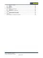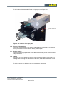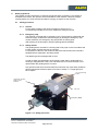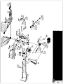
1
180 E. Hwy. 14, PO Box 850
Philip, SD 57567-0850
P: 605-859-2542 ● F: 605-859-2499
User manual
Universal pipe notcher
Type: AL150 230/460 Volt, 3-phase
ALMI Machinefabriek B.V., Vriezenveen
Doc.no.: 100287-HB-13 AL150 ENG
Revision and revision date: 2-20-09-2011
Page 1 of 28
1.
Foreword
This foreword contains general information about and for this user manual.
1.1.
Name of machine
The name of the machine is "Universal pipe notcher".
1.2.
Warning
Read this user manual carefully before use and before maintenance of the machine is
carried out. Only then is optimal safety ensured. The machine may only be operated and
maintained by personnel who have received special training.
There are moving parts on the machine!
For this reason, the machine must always be switched off and the electrical supply must be
disconnected before maintenance and/or repairs are carried out.
Always be careful of the moving, sharp and/or protruding parts; they can cause injury!
1.3.
Target group for each chapter
This user manual is intended to provide information to the persons/departments listed
below.
- the owner
- the operator
- the maintainer
Next to the heading of each chapter is indicated for which of the groups described above
the chapter is intended. Table 1.3-1 provides an overview of the target groups for each
chapter.
Chapter
Title
1
2
3
4
5
6
7
8
9
Table of contents
Foreword
Introduction
Safety regulations
General description of the machine
Transport, storage and setup of the machine
Operation of the machine
Maintenance of the machine
Trouble
Disposal of the machine
Owner
Operator
●
●
●
●
●
●
●
●
●
●
●
●
●
Maintaine
r
●
●
●
●
●
●
●
●
●
●
Table 1.3-1: Overview of the target groups for each chapter
1.4.
Symbols
The safety and caution symbols shown below are used in this document.
The information indicated by this symbol warns you of potential problems.
Furthermore, the symbol warns you that you can seriously injure yourself or
that you can seriously damage the machine.
1.5.
Re-ordering the user manual
Extra copies of the user manual are available (PDF) on the website. www.almi.nl
1.6.
Deficiencies in this user manual
This user manual was prepared with the greatest possible care. Should you, nonetheless,
find inaccuracies or deficiencies in the text, notify ALMI Machinefabriek BV of the problem.
ALMI Machinefabriek B.V., Vriezenveen
Doc.no.: 100287-HB-13 AL150 ENG
Revision and revision date: 2-20-09-2011
Page 2 of 28
Table of contents
Foreword .............................................................................................................................. 2
1.1. Name of machine ....................................................................................................... 2
1.2. Warning...................................................................................................................... 2
1.3. Target group for each chapter ................................................................................... 2
1.4. Symbols ..................................................................................................................... 2
1.5. Re-ordering the user manual ..................................................................................... 2
1.6. Deficiencies in this user manual ................................................................................ 2
Table of contents .......................................................................................................................... 3
Introduction................................................................................................................................... 5
1.7. The user ..................................................................................................................... 5
1.8. The manufacturer....................................................................................................... 5
1.9. Machine identification ................................................................................................ 5
1.10. Function of the machine............................................................................................. 6
1.11. Machine options ......................................................................................................... 6
1.12. Liability ....................................................................................................................... 6
1.13. Service ....................................................................................................................... 6
1.14. Warranty conditions ................................................................................................... 7
2. Safety regulations................................................................................................................. 8
2.1. Safety provisions........................................................................................................ 8
2.1.1. General ............................................................................................................ 8
2.1.2. Emergency stop............................................................................................... 8
2.1.3. Safety shields................................................................................................... 8
2.2. Warning symbols on the machine.............................................................................. 9
2.3. Safety regulations .................................................................................................... 10
2.4. The operator............................................................................................................. 10
2.5. The maintainer ......................................................................................................... 10
2.6. Setup of the machine ............................................................................................... 10
2.7. The noise emission of the machine ......................................................................... 11
2.8. Maintenance of the machine.................................................................................... 11
2.9. Summary of the safety regulations .......................................................................... 11
3. Description ......................................................................................................................... 12
3.1. General .................................................................................................................... 12
3.2. Construction of the machine .................................................................................... 12
3.3. Electrical supply ....................................................................................................... 13
3.4. Safety provisions and warning symbols................................................................... 13
3.5. Controls and adjustments ........................................................................................ 13
3.6. Operation ................................................................................................................. 14
3.6.1. Starting and stopping the grinding belt .......................................................... 14
3.6.2. Drive for the grinding belt............................................................................... 14
3.6.3. Securing a tubing section .............................................................................. 14
3.6.4. Angle adjustment ........................................................................................... 14
3.6.5. Stops.............................................................................................................. 14
3.6.6. Notching a tubing section .............................................................................. 15
3.6.7. Deburring ....................................................................................................... 15
3.6.8. Exchange of the grinding belt ........................................................................ 15
3.6.9. Exchange of the grinding roller ...................................................................... 16
3.6.10. Adjustment of the grinding roller and grinding belt ..................................... 17
3.6.11. Replacement of the hand wheel with a handle........................................... 19
3.7. Technical data.......................................................................................................... 20
4. Transport, storage, placement and initial setup ................................................................. 21
4.1. Scope of delivery...................................................................................................... 21
4.2. Assembly.................................................................................................................. 22
4.3. Placement of the machine ....................................................................................... 23
4.4. Connection of the power supply............................................................................... 23
4.5. Transport and storage.............................................................................................. 24
4.6. Initial setup ............................................................................................................... 24
5. Operation............................................................................................................................ 24
1.
ALMI Machinefabriek B.V., Vriezenveen
Doc.no.: 100287-HB-13 AL150 ENG
Revision and revision date: 2-20-09-2011
Page 3 of 28
6.
7.
8.
5.1. Operation in general ................................................................................................ 24
5.2. Start up..................................................................................................................... 24
5.3. Operation ................................................................................................................. 24
5.4. Shut down ................................................................................................................ 25
Maintenance....................................................................................................................... 25
6.1. Precautionary measures .......................................................................................... 25
6.2. Checkpoints ............................................................................................................. 25
6.3. Replacement of components ................................................................................... 26
Trouble ............................................................................................................................... 27
7.1. General information for trouble ................................................................................ 27
7.2. Trouble indications and signals................................................................................ 27
Disposal.............................................................................................................................. 27
EU Declaration of Conformity for machines ....................................................................... 28
ALMI Machinefabriek B.V., Vriezenveen
Doc.no.: 100287-HB-13 AL150 ENG
Revision and revision date: 2-20-09-2011
Page 4 of 28
Introduction
This chapter provides basic information about the machine and the accompanying user manual.
This chapter is intended for the owner, the operator and the maintainer of the machine.
1.7.
The user
Read this user manual carefully before use and before maintenance of the
machine is carried out. Only then is optimal safety ensured.
The machine may only be operated by qualified personnel. The operator must read the
chapters indicated in 1.3 carefully.
Maintenance of the machine may only be carried out by specially trained personnel from
the maintenance department. The maintainer must read the chapters indicated in 1.3
carefully.
1.8.
The manufacturer
The manufacturer of the machine is:
ALMI Machinefabriek BV
Wierdenseweg 82-86
7671 JK Vriezenveen
The Netherlands
T+31(0)546 561 353
F+31(0)546 564 465
1.9.
Machine identification
The machine is provided with the CE-mark. This is shown on the type plate. See Figure
1.9-1.
The CE-mark indicates that this machine satisfies the fundamental health and safety
requirements of the European Union. Also refer to the warning in section 1.2.
In addition to the CE-mark, the data indicated below is also shown on the type plate. See
also Figure 1.9-1.
- Name and address of the manufacturer
- Type indication
- Year of manufacture
- Serial number (only reference)
- Required supply voltage
- Motor speed
- Weight
ALMI Machinefabriek B.V.
Motor specifications
Type:
AL150
Voltage:
400
Year of
manufacture:
2009
Hz:
50
1/min:
2895
Weight
270 kilo
Serial no.: listed on the pipeclamp
Figure 1.9-1: Sample type plate with CE-mark
ALMI Machinefabriek B.V., Vriezenveen
Doc.no.: 100287-HB-13 AL150 ENG
Revision and revision date: 2-20-09-2011
Page 5 of 28
For the location of the attached CE-mark and type plate, see Figure 2.3.2.
Type plate with CE-mark
Figure 2.3.2: Location of the type plate
1.10. Function of the machine
The function of the machine is the notching and/or deburring of the ends of tube sections.
It is not permissible to use the machine for any other purpose.
1.11. Machine options
There is no optional equipment that can be added to the existing version of the machine to
change its function.
1.12. Liability
When injury or harm to persons or damage to the machine or products is the result of not
following these operating and maintenance instructions, ALMI Machinefabriek BV cannot
be held liable.
1.13. Service
For service contact your dealer or your own maintenance department.
ALMI Machinefabriek B.V., Vriezenveen
Doc.no.: 100287-HB-13 AL150 ENG
Revision and revision date: 2-20-09-2011
Page 6 of 28
1.14. Warranty conditions
art. 1 If within 12 months of delivery ALMI Machinefabriek BV is notified of deficiencies in
the delivered machine that are caused by defects in materials or workmanship and
is provided with the serial number and the original receipt, ALMI will repair these
defects.
art. 2 All warranty obligations expire if:
repairs or modifications are made to the machine by others, without instruction
from ALMI, in an incompetent manner;
non-original parts are used;
the damage or defects are the result of connecting the machine in a manner
other than intended, incompetent use, or failure to follow the regulations and
instructions for use;
the deficiencies are the result of normal wear of the machine.
art. 3 ALMI reserves the right to have work on the machine carried out by third parties
during and after the warranty period.
ALMI Machinefabriek B.V., Vriezenveen
Doc.no.: 100287-HB-13 AL150 ENG
Revision and revision date: 2-20-09-2011
Page 7 of 28
2.
Safety regulations
This chapter provides information concerning the general safety regulations. This chapter is
intended for the owner, the operator and the maintainer of the machine. Read this chapter
carefully before use of the machine and before carrying out repairs on the machine.
2.1.
Safety provisions
2.1.1. General
For the exact location of the various provisions, see Figure 3.1.1.
It is absolutely forbidden to remove or disable the safety provisions.
2.1.2. Emergency stop
The machine is provide with an emergency stop. The emergency shall break the
electrical supply. Unbreak the electrical supply by twisting the emergency stop
counter clockwise, the emergency stop jumps back in starting point.
After pushing of the emergency stop the grinding belt will standstill.
2.1.3. Safety shields
The grinding belt is enclosed in a housing that is only open on the front side at the
location where the tube sections are notched.
For protection of the face, the location at which the tube sections are notched is
equipped with a transparent, fold-away shield.
The deburring area is equipped with a cover.
In order to allow the replacement of the grinding roller and/or grinding belt, the
housing is equipped with a side cover The side cover must never be open or be
opened when the grinding belt is in motion.
Only personnel that have received sufficient instruction may open safety shields to
perform maintenance and/or repairs. Also refer to section 1.3 “Target group for
each chapter”.
Top cover deburring
location
Transparent, fold-away
shield for facial
protection
Side cover
Emergency stop
Figure 3.1.1: Safety provisions
ALMI Machinefabriek B.V., Vriezenveen
Doc.no.: 100287-HB-13 AL150 ENG
Revision and revision date: 2-20-09-2011
Page 8 of 28
2.2.
Warning symbols on the machine
The following warning symbols can be found on the machine. For the location of the
warning symbols on the machine see Figure 3.2.1
It is absolutely forbidden to remove the warning symbols or make them unreadable by any
means.
Worn warning symbols must be replaced in a timely manner.
Pictogram 1:
Read the user manual first!
Pictogram 2:
Use of eye and hearing protection required!
Pictogram 3:
Use of light respiratory protection required!
Pictogram 4:
Use of safety gloves required!
Pictograms 1 through 4
Figure 3.2.1: Warning symbols on the machine
ALMI Machinefabriek B.V., Vriezenveen
Doc.no.: 100287-HB-13 AL150 ENG
Revision and revision date: 2-20-09-2011
Page 9 of 28
2.3.
Safety regulations
Although the machine satisfies the fundamental health and safety requirements of the
European Union, dangerous situations can always occur. Always remain alert for possible
dangerous situations. Be careful of projecting portions of the machine. Be careful with
loose clothing and hair.
At a minimum, the following safety regulations must be followed:
- Never engage power to the machine if any person is in contact with the machine in a
dangerous manner.
- Never start the machine if any person is in contact with the machine in a dangerous
manner.
- During maintenance to the machine, switch off the machine and disconnect the
electrical plug.
- Follow the warnings and indications on the machine. For the explanation of the
symbols, see section 2.2.
- Before use of the machine, close the side cover.
- Close the top cover if deburring is not required.
- Use the fold-away shield to protect your face.
- Wear close-fitting clothing during grinding work.
- Before grinding, attach the workpiece securely.
- No flammable materials may be present in the area surrounding the universal pipe
notcher. The grinding of pipes creates showers of sparks.
- Wear safety gloves during grinding operations, changing of the grinding roller and/or
grinding belt, and during adjustment operations.
Through intensive use, the roller can become extremely hot, and as a result of
grinding, sharp burrs can be created.
Always think of the safety of yourself and others!
2.4.
The operator
The machine may only be operated by personnel who are qualified to do so. Personnel
that have this qualification are referred to in the rest of this user manual as the operator. As
operator of the machine, you must be aware of the information that is relevant for you. Also
refer to section 1.3 “Target group for each chapter”. The operator is not permitted to
perform operations that are not indicated to be intended for the operator. Comply with the
safety regulations in this user manual. Do not deviate from the safety regulations. This can
result in danger.
2.5.
The maintainer
Only personnel from the maintenance department who have received special training may
carry out maintenance of the machine. Personnel that have this qualification are referred to
in the rest of this user manual as the maintainer. As maintainer of the machine, you must
be aware of the information that is relevant for you. Also refer to section 1.3 “Target group
for each chapter”. Comply with the safety regulations in this user manual. Do not deviate
from the safety regulations. This can result in danger.
2.6.
Setup of the machine
Make sure that the machine is setup and properly anchored on a flat, horizontal floor
during use.
Make sure there is sufficient lighting to allow the work to be performed in a safe and
responsible manner.
ALMI Machinefabriek B.V., Vriezenveen
Doc.no.: 100287-HB-13 AL150 ENG
Revision and revision date: 2-20-09-2011
Page 10 of 28
2.7.
The noise emission of the machine
The noise emission during grinding operations is 83-87 dB(A), measured at a distance of 1
metre. The use of good hearing protection is required.
2.8.
Maintenance of the machine
The machine must be in a sufficient state of repair that no dangerous situations can occur.
The troubleshooting chart is provided in chapter 6. If replacement is necessary, use only
original parts.
2.9.
Summary of the safety regulations
- The machine may only be operated by personnel who are qualified to do so.
- As operator of the machine, you must be aware of the information that is relevant for
you. Also refer to section 1.3 “Target group for each chapter”.
- The operator is not permitted to perform operations that are not indicated to be
intended for the operator.
- Only personnel from the maintenance department who have received special training
may carry out maintenance of the machine.
- As maintainer of the machine, you must be aware of the information that is relevant for
you. Also refer to section 1.3 “Target group for each chapter”.
- Always remain alert for possible dangerous situations. Be careful of projecting portions
of the machine. Be careful with loose clothing and hair.
- Never engage power to the machine if any person is in contact with the machine in a
dangerous manner.
- Never start the machine if any person is in contact with the machine in a dangerous
manner.
- During maintenance to the machine, switch off the machine and disconnect the
electrical plug.
- Follow the warnings and indications on the machine. For the explanation of the
symbols, see section 2.2.
- Before use of the machine, close the side cover.
- Close the top cover if deburring is not required.
- Use the Lexan fold-away shield to protect your face.
- Wear close-fitting clothing during grinding work.
- Before grinding, attach the workpiece securely.
- No flammable materials may be present in the area surrounding the universal pipe
notcher. The grinding of pipes creates showers of sparks.
- Wear safety gloves during grinding operations, changing of the grinding roller and/or
grinding belt, and during adjustment operations.
Through intensive use, the roller can become extremely hot, and as a result of
grinding, sharp burrs can be created.
ALMI Machinefabriek B.V., Vriezenveen
Doc.no.: 100287-HB-13 AL150 ENG
Revision and revision date: 2-20-09-2011
Page 11 of 28
3.
Description
This chapter provides general information about the machine. This chapter is intended for the
owner, the operator and the maintainer of the machine.
3.1.
General
This user manual includes an appendix with an exploded view drawing with drawing
number 3.1500.000 1A.
This drawing includes a parts list containing the name of each part.
3.2.
Construction of the machine
The machine consists primarily of the components shown in Figure 4.2.1.
Drive motor
Tightening mechanism, grinding belt
Adjustment
mechanism, grinding
roller
Grinding roller
Tube clamp
Housing, drive
roller, grinding
roller and
grinding belt
Cross support
Support pillar
Grinding waste container
Foot plate
Figure 3.2-1: Construction of the machine
ALMI Machinefabriek B.V., Vriezenveen
Doc.no.: 100287-HB-13 AL150 ENG
Revision and revision date: 2-20-09-2011
Page 12 of 28
3.3.
Electrical supply
For the electrical connection, the machine is equipped with a 4-conductor supply cable
without a plug. The machine is equipped with a "Euro-voltage" motor. This means that the
motor can be connected to a 230 Volt, 3-phase or 400 Volt, 3-phase supply with a
tolerance of ±10%.
When the machine is connected for the first time, the voltage of the supply connection
must be verified in comparison to the connection voltage indicated on the type plate and
the correct plug must be installed. For the electrical connection, follow the instructions in
section 4.6.
3.4.
Safety provisions and warning symbols
The safety provisions and warning symbols are handled in sections 2.1 and 2.1.
3.5.
Controls and adjustments
For regular operation, the machine has the following controls and adjustments.
The controls and adjustments are shown in Figure 4.5.1.
a. Emergency stop
b. Push button for stopping the grinding belt
c. Push button for starting the grinding belt
d. Hand wheel for adjusting support parallel to grinding roller
e. Hand wheel for adjusting support perpendicular to grinding roller (can be replaced with
a handle, see section 4.6.11.
f. Clamp handle for securing workpiece
g. Allen bolt for securing rotatable clamp (using key with handle “j”)
h. Allen bolt for securing standard stopper (using key with handle “j”)
i. Allen bolt for securing grinding belt (using key with handle “j”)
j. Allen key, 8 mm, with handle; for securing rotatable tubing clamp, for securing
standard stopper, and for adjustment of grinding belt
k. Allen bolt for opening and closing side cover
Controls and adjustments for changing and adjusting grinding belt and/or grinding roller
are described in sections 3.6.8, 3.6.89 and 3.6.810.
j.
k.
i.
a.
c
g.
b.
f.
e.
d.
h.
Figure 3.5-1: Controls and adjustments
ALMI Machinefabriek B.V., Vriezenveen
Doc.no.: 100287-HB-13 AL150 ENG
Revision and revision date: 2-20-09-2011
Page 13 of 28
3.6.
Operation
3.6.1. Starting and stopping the grinding belt
The switches for starting and stopping are on the right side of the support pillar.
See figure Figure 4.5.1.
To start the machine, push the green button.
To stop the machine, push the red button.
ATTENTION! Before the machine is started, the side cover must be closed. The
side cover is shown in Figure 3.1.1.
3.6.2. Drive for the grinding belt
The grinding belt is driven by a "Euro-voltage" motor. This means that the motor
can be connected to a 230 Volt, 3-phase or 400 Volt, 3-phase supply with a
tolerance of ±10%.
Before first use, the voltage of the supply connection must be verified in
comparison to the voltage indicated on the type plate. For the electrical connection,
follow the instructions in section 4.6.
A pulley with a rubber coating is mounted on the motor shaft. The rubber coating,
in combination with the correct belt tension, ensures the required grip of the
grinding belt to the pulley.
Before putting tension on the grinding belt, see section 4.6.8.
The required direction of rotation is indicated on the pulley. Consider this when
making the electrical connection. For the electrical connection, follow the
instructions in section 4.6.
The direction of rotation is also indicated on the inside of the grinding belt. This
must match the arrow on the pulley.
Before installation of the grinding belt, see section 4.6.8.
3.6.3. Securing a tubing section
For working, the tubing section must be secured in the tubing clamp.
The tubing clamp is mounted on the cross support. See Figure 4.5.1.
The tubing clamp with V-shaped side plates is suitable for clamping tubing with a
diameter of 18 - 144.3 mm.
When the V-shaped side plates are removed, the tubing clamp can also be used to
secure rectangular- and square-profile tubing. In the case of rectangular- and
square-profile tubing, the centre of the tubing profile must be at the same height as
the centre of the grinding roller. To achieve the correct height of the tubing profile,
a fill block can be used under the tubing section.
The clamp can be secured with the clamp handle on the tubing clamp.
See Figure 4.5.1.
3.6.4. Angle adjustment
To adjust the angle, Allen head bolt "f" must be loosened.
The scale divisions allow the correct angle to be set.
In relation to the grinding roller, the clamp in adjustable from 90 to 30 degrees.
After adjustment, the Allen bolts "f" must be re-tightened.
3.6.5. Stops
Under the cross support of the tubing clamp is a clamp block "g" with which a
standard stopper can be adjusted. See Figure 4.5.1.The stopper works to prevent
the movement of the support toward the grinding roller. The stopper can be
secured with an Allen bolt.
The flat side of the clamp has two M8-threaded holes. See Figure 4.5.1.
A length stopper can be attached to these.
The stoppers are designed to ensure that a series of tubing sections with the same
dimensions are notched to an equal depth.
ALMI Machinefabriek B.V., Vriezenveen
Doc.no.: 100287-HB-13 AL150 ENG
Revision and revision date: 2-20-09-2011
Page 14 of 28
The length stopper is not included with the machine and must be made by the
user.
3.6.6. Notching a tubing section
After the tubing section has been clamped and the correct angle and stoppers are
set up, the slide with hand wheel "c" must be positioned so the tubing section that
is to be notched is moved toward the centre of the grinding roller. Hand wheel "d" is
used to adjust the support perpendicular to the grinding roller. By moving the
support toward the grinding roller, the tubing section can be notched. Care must be
given to ensure that the width of the notch does not exceed the width of the
grinding belt.
In place of the hand wheel, a handle can be installed. See section 4.6.11..
3.6.7. Deburring
The top of the machine is equipped with a deburring table for deburring the
notched tubing section. See Figure 3.6-1. For deburring, the top cover must be
opened. The cover is shown in Figure 3.1.1.
Figure 3.6-1: Deburring table
3.6.8. Exchange of the grinding belt
Before the grinding belt is exchanged, the machine must be disconnected from the
electrical supply by removing the plug connection from the mains supply. Also read
the safety regulations in section 2.3.
Wear safety gloves during exchange of the grinding roller and/or grinding belt.
Through intensive use, the roller can become extremely hot.
To create the room that is necessary for exchange of the grinding belt, the support
must be moved as far as possible from the grinding roller with hand wheel "d".
Hand wheel "d" is shown in Figure 4.5.4. In place of the hand wheel, a handle can
be installed. See section 4.6.11..
To gain access to the grinding belt, the side cover and the top cover must be
opened. The covers are shown in Figure 3.1.1.
To remove the belt, the tension on the belt must be released and the support for
the grinding roller must be released.
The belt tension can be released by turning the hand crank counter-clockwise. The
position of the belt-tension device is shown in Figure 3.2-1. The belt-tension
mechanism with hand crank is shown in Figure 3.6-3.
The support for the grinding roller can be released by loosening the wingnuts. The
support is shown in Figure 3.6-2.
ALMI Machinefabriek B.V., Vriezenveen
Doc.no.: 100287-HB-13 AL150 ENG
Revision and revision date: 2-20-09-2011
Page 15 of 28
Figure 3.6-2: Support for the grinding roller
Hand crank
Adjust to 3-5 mm
during tensioning of the grinding belt
Figure 3.6-3: Belt-tensioning device
The grinding belt can now be removed.
Remove all remnants.
During installation of a new grinding belt, the required direction of rotation for the
belt must match that of the pulley. An arrow is shown on both the inside of the belt
and the pulley. Begin by placing the new grinding belt on the side of the grinding
roller. For correct selection of a grinding belt, see section 3.7.
ADVICE: For a grinding roller with a diameter smaller than 30 mm, use a grinding
belt that has previously been used on a roller with a larger diameter. A new
grinding belt is very stiff and may break if used on a grinding roller with a small
diameter.
After installing the new grinding belt, the belt must be tensioned properly. This can
be done by turning the hand crank clockwise until the area between the ring and
the plate is 3-5 mm. See Figure 3.6-3.
The tension is determined by the degree to which the spring is compressed.
Next, the support for the grinding roller must be moved back to its original position
and secured with the wingnuts. See Figure 3.6-2.
After exchange of the grinding belt, any misalignment of the belt must be corrected.
For more information, see section 3.6.10.
3.6.9. Exchange of the grinding roller
Before the grinding roller is exchanged, the machine must be disconnected from
the electrical supply by removing the plug connection from the mains supply. Also
read the safety regulations in section 2.3.
ALMI Machinefabriek B.V., Vriezenveen
Doc.no.: 100287-HB-13 AL150 ENG
Revision and revision date: 2-20-09-2011
Page 16 of 28
Wear safety gloves during exchange of the grinding roller and/or grinding belt.
Through intensive use, the roller can become extremely hot.
Before the grinding roller is exchanged, the grinding belt must be removed. For
more information, see section 3.6.8.
The grinding roller is held in place by two spring-pressure retainers.
The grinding roller can be easily removed from the holder as shown in Figure
3.6-4.
Never adjust the spring-pressure retainers. They have been properly adjusted by
the manufacturer.
Clean recesses
thoroughly
Spring-pressure retainers
Bearings
Supports for the grinding
roller
Figure 3.6-4: Exchange of the grinding roller
Before the new grinding roller is installed, the recesses of the support for the
grinding roller must be cleaned thoroughly. This prevents clamping problems.
Thereafter, the new grinding roller can be installed.
The grinding belt can also be re-installed. For more information, see section 3.6.8.
For an overview of the available grinding-roller diameters, see section 3.7.
ADVICE: For a grinding roller with a diameter smaller than 30 mm, use a grinding
belt that has previously been used on a roller with a larger diameter. A new
grinding belt is very stiff and may break if used on a grinding roller with a small
diameter.
ATTENTION! The bearings that are mounted on the grinding roller must be
handled with care because they can be easily damaged.
After exchange of the grinding roller, any misalignment (diagonal running) of the
belt must be corrected. For more information, see section 3.6.10.
3.6.10. Adjustment of the grinding roller and grinding belt
During first use, see chapter 4, and after exchange of the grinding belt and/or
grinding roller, the adjustment of the grinding roller and the grinding belt must
always be checked.
The centre of the grinding roller must be at the same height as the centre of the
tubing, and the belt may not run diagonally during operation.
Before the grinding roller is adjusted, the machine must be disconnected from the
electrical supply by removing the plug connection from the mains supply. Also read
the safety regulations in section 2.3.
Wear safety gloves during adjustment operations. Through intensive use, the roller
can become extremely hot.
Before adjustment, the two wingnuts of the support for the grinding roller, see
Figure 3.6-2, must be loosened one turn.
ALMI Machinefabriek B.V., Vriezenveen
Doc.no.: 100287-HB-13 AL150 ENG
Revision and revision date: 2-20-09-2011
Page 17 of 28
Adjustment of the centre height:
The height is adjusted as well as possible by the manufacturer. If the centre of the
tubing profile is not at the same height as the centre of the grinding roller, the
height of the grinding roller must be adjusted. For more information, see Figure
3.6-5.
After loosening bolts "R", the height of the grinding roller can be adjusted.
After adjustment, re-tighten bolts "R".
Figure 3.6-5: Adjustment of the centre height of the grinding roller
Adjustment of the grinding roller in relation to the grinding belt
For adjustment of the grinding roller in relation to misalignment of the grinding belt,
see also Figure 3.6-6.
Figure 3.6-6: Adjustment of the grinding roller in relation to the grinding belt
Turn bolt P in either direction until the misalignment has been corrected. For a
rough adjustment, the grinding belt should be driven by hand (by turning the drive
roller on the motor shaft). For fine adjustment, the motor can be switched on.
ATTENTION! First close the side cover! See
Figure.
Comply with the safety regulations in section 2.3.
ATTENTION! After adjustment, the two wingnuts of the support for the grinding
roller, see Figure 3.6-2, must be re-tightened.
ALMI Machinefabriek B.V., Vriezenveen
Doc.no.: 100287-HB-13 AL150 ENG
Revision and revision date: 2-20-09-2011
Page 18 of 28
3.6.11. Replacement of the hand wheel with a handle
To replace hand wheel “d” with the provided handle, the procedure below must be
carried out. For clarification, also see Figure 3.6-7 and Figure 3.6-8.
Removal of the spindle:
Position the slide as far as possible from the grinding roller.
Remove the hand wheel.
Push the slide as far as possible toward the rear.
Remove the slide from the backside.
Figure 3.6-7: Removal of the hand wheel and spindle
Installation of the handle:
Remove the bolts and the spacer bushes on the bottom.
There is a spacer ring under the long spacer bush.
Install the handle in accordance with Figure 3.6-8.
Make sure the spacer ring is reinstalled.
Figure 3.6-8: Installation of the handle
ALMI Machinefabriek B.V., Vriezenveen
Doc.no.: 100287-HB-13 AL150 ENG
Revision and revision date: 2-20-09-2011
Page 19 of 28
3.7.
Technical data
Type
Serial number
Weight
Measurements
Motor
AL150
Is indicated on the top of the clamp. See Figure 3.7-1.
270 kg
lxbxh=1450x1200x850 mm
Squirrel-cage armature motor SG112M, 4 kW, suitable for
supply voltage of 230 V or 460 V.
Motor speed:
2895 rpm at 460V/50Hz
3420 rpm at 230V/60Hz
The motor includes thermal protection and a switch with a
no-voltage coil.
Versions of motor
Voltage 230 V:
switches and no-voltage switch SELRD21 1-18
coils
no-voltage coil U-PKZM1-230
Voltage 460 V:
switch SELRD21 1-10
no-voltage coil U-PKZM1-400
Belt speed
30 m/s at 460V/50Hz
36 m/s at 230V/60Hz
Notching depth
Ø20-ø114.3 mm.
Grinding roller
For available grinding roller diameters, see Table 3.7-1.
Grinding belt
Measurements: lxb=2000x150 mm (79”x6”)
The machine is delivered standard with 2 grinding belts,
type RX66, grit K36
For recommended grinding belts, see Table 3.7-2
83-87 dB(A) measured at a distance of 1 metre from the
Noise emission
machine.
Figure 3.7-1: Location of serial number
Range ø20-ø114.3 mm
diameters increasing in steps of 2 mm
Special diameters
½”, ¾”,1”, 1¼”, 1½”, 2”, 4”
Other diameters between ø20 and
Other diameters are available from your
ø114.3 mm
dealer upon request.
Table 3.7-1: Other available grinding roller diameters
Steel
Stainless steel
Aluminium
Grinding roller
diameter
type
grit
type
grit
type
grit
ø18 t/m ø40 mm
R822
36
R902
150
R822
36
ø40 t/m ø114.3 mm R845
36
R981
36
R822
36
Table 3.7-2: Overview of recommended grinding belts
ALMI Machinefabriek B.V., Vriezenveen
Doc.no.: 100287-HB-13 AL150 ENG
Revision and revision date: 2-20-09-2011
Page 20 of 28
4.
Transport, storage, placement and initial setup
This chapter provides information about the scope of delivery, transport, storage, placement and
initial setup of the machine. This chapter is intended for the maintainer of the machine.
4.1.
Scope of delivery
The machine is delivered in a wooden crate.
The following loose components are included in the scope of delivery:
part
1
2
3
4
5
6
7
8
9
10
11
12
13
14
quantity
1
1
1
2
1
1
1
2
1
1 Set
1
1 Set
1
1
description
Universal pipe notcher
Foot plate
Support pillar
Hex bolt with washer M12
Grinding waste container (in the support pillar)
Hand wheel (in the support pillar)
Handle (in the support pillar)
Grinding belt (in the support pillar)
Allen key, 8 mm, with handle
Attachment hardware (in the support pillar)
Power supply cable without plug
Grinding rollers and belts (if ordered separately)
User manual
“exploded view” tekening met tekeningnummer 3.1500.000
1A
ALMI Machinefabriek B.V., Vriezenveen
Doc.no.: 100287-HB-13 AL150 ENG
Revision and revision date: 2-20-09-2011
Page 21 of 28
4.2.
Assembly
For clarification of the procedures below, see also Figure 4.2-1.
Lifting eye
Handle
Grinding waste container
M12 bolts
Support pillar
Foot plate
Figure 4.2-1: Clarification of assembly
-
-
-
Remove loose components from the packaging.
Inside the support pillar you will find a box with any ordered grinding belts and grinding
rollers, the grinding waste container, the hand wheel, the handle and the attachment
hardware.
Remove the two attachment bolts with which the universal pipe notcher is attached to
the bottom plate of the packaging.
Remove the wood screws with which the support pillar and foot plate are attached to
the crate.
Remove the support pillar from the packaging and attach them together.
ATTENTION! Inside the support pillar you will find a box with any ordered grinding
belts and grinding rollers, the grinding waste container, the hand wheel, the handle
and the attachment hardware.
Remove the machine from the packaging. To do so, use the lifting eye. Use the proper
lifting equipment. The machine weighs 270 kg.
Open the side cover of the machine.
Attach the machine to the support pillar using two M12 hex bolts.
Slide the grinding waste container under the machine.
Install the included hand wheel on the front of the cross support.
Handle installation
Figure 4.2-2: Installation of the hand wheel and handle
ALMI Machinefabriek B.V., Vriezenveen
Doc.no.: 100287-HB-13 AL150 ENG
Revision and revision date: 2-20-09-2011
Page 22 of 28
-
To test the direction of rotation and for adjustment during the initial setup, also install a
grinding roller and a grinding belt See sections 4.4 and 4.4. For the installation of the
grinding belt and the grinding roller, see sections 3.6.8 and 3.6.8.
4.3.
Placement of the machine
Make sure that the machine is setup and properly anchored on a flat, horizontal floor
during use.
Make sure there is sufficient lighting to allow the work to be performed in a safe and
responsible manner.
4.4.
Connection of the power supply
For the electrical connection, the machine is equipped with a 4-conductor supply cable
without a plug. The machine is equipped with a "Euro-voltage" motor. This means that the
motor can be connected to a 230/460 Volt, 3-phase supply with a tolerance of ±10%.
The voltage of the supply connection must be verified in comparison to the connection
voltage indicated on the type plate.
If the voltages are not the same, the adaptations described below must be made.
- Open the connection compartment of the electrical motor and install the strips as
shown in Figure 4.4-1.
- Replace the motor switch and the no-voltage coil. Section 3.7 shows what is required.
- Replace the type plate of the machine.
The motor switch, the no-voltage coil and the type plate are available through your dealer.
460VOLT
Figure 4.4-1: Wiring connections in the connection compartment of the electrical
motor
Connect the supply cable wires according to the correct diagram in Figure 4.4-1. Install a
plug that matches your electrical outlet on the end of the cable. After connection, check the
direction of rotation of the grinding belt. The top surface must move toward the cross
support.
ATTENTION! First close the side cover! See
Figure.
Comply with the safety regulations in section 2.3.
If necessary, exchange the concerned wires in the plug.
Route the cable to the electrical outlet in such a manner that it will not be tripped over.
ALMI Machinefabriek B.V., Vriezenveen
Doc.no.: 100287-HB-13 AL150 ENG
Revision and revision date: 2-20-09-2011
Page 23 of 28
4.5.
Transport and storage
The machine is delivered in a wooden crate. The crate can be lifted and moved with a
forklift.
Once the machine has been assembled, it is sensible to lay the machine on a pallet when
it must be moved or stored.
It can then be moved with a forklift.
For vertical lifting, the machine is also equipped with a lifting eye. This lifting eye can be
used to set the machine upright.
4.6.
Initial setup
During first use and after exchange of the grinding belt and/or grinding roller, the
adjustment of the grinding roller and the grinding belt must always be checked.
The centre of the grinding roller must be at the same height as the centre of the tubing,
and the belt may not run diagonally during operation.
For the adjustment procedures, see the description in section 3.6.10.
Once the machine is plugged into the mains supply, the machine is ready for use.
5.
Operation
This chapter provides information about the operation of the machine. This chapter is intended
for the operator and the maintainer of the machine.
5.1.
Operation in general
The following is a description of regular operation.
Comply with the safety regulations in chapter 2.
Operation is carried out using the controls and adjustments described in section 3.5.
For additional information also see section 3.6, the "Operation" of the machine.
5.2.
Start up
- Connect the machine to the mains supply, if it is not already connected.
- Check whether the correct grinding belt is installed. For selection of the proper grinding
belt, see Table 3.7-2. Check the grinding belt for wear. If it is necessary to replace the
grinding belt, see section 3.6.8.
- Check whether the correct grinding roller is installed. The correct grinding roller is
determined by the diameter measurement of the tubing sections that must be
connected to one another. For available grinding roller diameters, see Table 3.7-1 If it
is necessary to replace the grinding roller, see section 3.6.9.
- Check the adjustment of the grinding roller and the grinding belt. The centre of the
grinding roller must be at the same height as the centre of the tubing, and the belt may
not run diagonally during operation. For the adjustment procedures, see the
description in section 3.6.10.
- Check whether the grinding waste container must be emptied.
5.3.
Operation
- Before securing rectangular- or square-profile tubing, remove the side plates from the
clamp. If necessary, use a fill block to maintain the correct centre height of the tubing
section. See also section 3.6.3.
- Secure the tubing section in the tubing clamp.
- Set the proper angle. Tighten the clamp.
- Bring the tubing section toward the centre of the grinding roller.
- Start the machine. To do so, push the green button on the motor switch.
- Move the tubing section toward the grinding roller for notching. The width of the notch
must not exceed the width of the grinding belt.
- To notch a series of tubing sections that have the same diameter and length, the
stoppers can be used. For more information, see section 3.6.5.
ALMI Machinefabriek B.V., Vriezenveen
Doc.no.: 100287-HB-13 AL150 ENG
Revision and revision date: 2-20-09-2011
Page 24 of 28
5.4.
6.
After notching the tubing section, it can be deburred on the deburring table at the top
of the machine. To do so, open the top cover.
Stop the machine. To do so, push the red button on the motor switch.
Shut down
The machine can be shut down by removing the plug from the mains connection.
Maintenance
This chapter provides information about the maintenance of the machine. This chapter is
intended for the maintainer of the machine.
6.1.
Precautionary measures
Maintenance of the machine may only be performed if the machine if
voltage free. Comply with the safety regulations in chapter 3.
6.2.
Checkpoints
The machine must regularly be checked according to the points in Table 6.2-1. Replace
components as necessary. See section 6.3.
Item number Description
1
Check the presence and proper
operation of safety shields. See section
2.1.
Check the operation of the closing
mechanism for the side cover.
Check the visibility through the
transparent shield above the grinding
roller
2
Check the presence and legibility of the
warning symbols. See section 2.2. Worn
or removed symbols must be replaced.
3
Check for wear of the grinding-roller
bearings. See also section 3.6.9.
4
Check the operation of the tubing clamp,
bolts and screw threads used to secure
and adjust a tubing section. See also
sections 3.6.3, 3.6.3 and 3.6.3.
5
Check the wear of the rubber coating on
the drive roller. The coating ensures the
proper grip of the grinding belt to the
drive unit. See also section 3.6.2.
6
Check the proper operation of the belttensioning device. See also section
3.6.8.
7
Check the operation of the adjustment
mechanism for the grinding roller. See
also section 3.6.10.
8
Thoroughly clean the machine on a
regular basis.
9
Check the mains cable for damage.
Table 6.2-1: Checkpoints and lubrication schedule
ALMI Machinefabriek B.V., Vriezenveen
Doc.no.: 100287-HB-13 AL150 ENG
Revision and revision date: 2-20-09-2011
Page 25 of 28
Time interval
Monthly
Monthly
Every 6 months
Every 6 months
Every 6 months
Every 6 months
Every 6 months
Monthly
Monthly
6.3.
Replacement of components
If the machine requires repair, we recommend that you contact your dealer. If you carry out
repairs yourself, you must only use original parts.
When ordering parts, the following information must be provided:
- The machine type number,
The machine type number is indicated on the type plate.
- The machine serial number;
The machine serial number is indicated on the top of the clamp. See Figure 3.7-1.
- The part number,
The part number is indicated on the exploded view drawing provided with this user
manual, drawing number 3.1500.000 1A.
ALMI Machinefabriek B.V., Vriezenveen
Doc.no.: 100287-HB-13 AL150 ENG
Revision and revision date: 2-20-09-2011
Page 26 of 28
7.
8.
Trouble
This chapter provides information about trouble and trouble indications. This chapter is intended
for the operator and the maintainer of the machine.
7.1.
General information for trouble
When trouble occurs, switch off the machine and contact your dealer or your own
maintenance department.
Comply with the instructions in chapter 2 and the maintenance instructions in chapter 2.
7.2.
Trouble indications and signals
The machine controls do not include trouble indications or other signals.
Disposal
This chapter provides information about the disposal of the machine. This chapter is intended for
the owner and the maintainer of the machine.
The machine must be disposed of in accordance with the legal requirements of the country in
which it is used.
The owner is responsible for disposal of the machine.
ALMI Machinefabriek B.V., Vriezenveen
Doc.no.: 100287-HB-13 AL150 ENG
Revision and revision date: 2-20-09-2011
Page 27 of 28
EU Declaration of Conformity for machines
(Directive 2006/42/EG, art. 6 sec 2 and Appendix II A)
Manufacturer:
Address:
Postcode and city:
ALMI Machinefabriek BV
Wierdenseweg 82-86
7671 JK Vriezenveen
Hereby declares that:
The universal pipe notchers
With
type numbers AL100, AL100U-01, AL100U-02 and AL150
-
in conformance with the machinery directive 2006/42/EG,
-
satisfy the requirements of the following other EU directives:
73/23/EEC – Low-voltage direction, as modified in the directive 93/68/EEC
2004/108/EG – EMC directive, as modified in directive 89/336/EEC
and that
-
the following European Standards have been applied:
NEN-EN-ISO 12100:2010 - Safety of machinery - General principles for design
- Risk assessment and risk reduction
NEN-EN 60204-1:2006 Safety of machinery - Electrical equipment of machines - Part 1: General
requirements.
Completed in Vriezenveen, 1 november 2011
Signature:
J. J. Landhuis
General Director
ALMI Machinefabriek B.V., Vriezenveen
Doc.no.: 100287-HB-13 AL150 ENG
Revision and revision date: 2-20-09-2011
Page 28 of 28
1
2
3
4
5
6
7
8
9
10
11
12
13
14
15
16
17
18
19
20
21
22
23
24
1
A
A
2
3
B
B
89
4
C
C
35
59
36
60
8
9
10
D
5
37
6
38
7
E
11
47
12
48
13
20
14
49
88
26
61
46
88
D
62
88
59
60
E
54
15
50
10
55
51
16
56
91
17
F
45
57
58
91
F
18
96
1
Steunas (gelagerd sam)
04.00316
000
39
95
1
Schakelaar (sam)
04.00292
001
94
1
Sticker zijklep 13x5 cm
A050.00025
000
40
93
1
Motor 230/400V 60Hz 3 fase 4kW E030.00004
000
92
1
Type AL43SH 8,5 x 8 cm
A050.00024
000
41
91
5
Bzk.ck.schr. M6x10 ev. 8.8
07160.M6x10
000
90
1
Zk.moer M10 ev. 8
01300.M10
000
89
4
Bzk.ck.schr. M6x20 ev. 8.8
07160.M6x20
000
88
3
Vlk.sluitr. M16 ev. zf.
38130.M16
000
87
1
Schuurband R929 150x2000 P36
A044.00004
000
86
1
Vlk.sluitr. M10 ev. bv.
37420.M10
000
85
1
Zk.tapbout M10x40 ev. 8.8
01210.M10x40
000
84
1
Sluitring
04.00049
000
19
83
1
Poellie
04.00193
000
82
1
Schuurband RX66 150x2000 P36
A044.00002
000
20
81
1
Bzk.ck.schr. M16x50 ev. 8.8
07160.M16x40
000
80
1
Scharnieras
04.00189
000
21
79
1
Sluitring
04.00264
000
78
1
Motorstoel (sam)
04.00188
000
22
77
4
Bzk.lk.schr. M6x16 ev. 10.8
07141.M6x16
000
76
1
Voet (sam)
04.00224
000
20
75
1
Zuil (sam)
04.00222
001
74
1
Almi sticker middel 14,8x4,6cm
A050.00002
000
23
73
1
Plaat (sam)
04.00314
000
72
2
Vlk.sluitr. M12 ev. zf.
38130.M12
000
2x tbv 04.00311 Zak (sam)
71
2
Zk.tapbout M12x35 ev. 8.8
01210.M12x35
000
2x tbv 04.00311 Zak (sam)
70
1
Klep (sam)
04.00243
000
69
1
Bzk.ck.schr. M10x16 ev. 8.8
07160.M10x16
000
85
68
1
Deursluiting
04.00045
000
67
1
Sterknop 13345
M040.00003
000
86
66
1
Deursluiting
04.00187
000
2
65
1
Afvalbak
04.00202
000
64
1
Steunas
04.00209
000
63
4
Zk.tapbout M10x20 ev. 8.8
01210.M10x20
000
62
1
Drukv. d=4 DM=21,5 LO=80
M090.00007
000
61
1
Kantelblok
04.00048
000
60
2
Moer
04.00064
000
59
2
Bzk.st.schr. M5x6 45H ke.
07840.M5x6
000
58
1
Zk.tapbout M12x30 ev. 8.8
01210.M12x30
000
57
1
Vlk.sluitr. M12 ev. d2=3xd1
38210.M12
000
56
1
Spindel (sam)
04.00307
000
83
55
1
Hijsplaat
04.00210
000
54
1
Lageras (sam)
04.00309
000
84
53
1
Kap (sam)
04.00203
000
52
1
Grafietband 150mm
04.00214
000
35
51
1
Afdekplaat
04.00257
000
50
1
Inbussl.dw.greep slw8x200
M130.00002
000
49
1
Zk.borgmoer M8 ev. 8
12300.M8
000
48
1
Stempelveer 25/12,5x38
M090.00002
000
47
1
Pijp
04.00185
000
46
1
Zk.moer M8 ev. 8
01300.M8
000
45
1
Zk.tapbout M8x100 ev. 8.8
01210.M8x100
000
44
1
Aanslag
04.00171
000
43
1
Anti-trilstrip
04.00186
000
42
1
Beschermglas
04.00206
000
41
3
Bzk.vk.schr. M3x10 ev. 8.8
07470.M3x10
000
40
3
Vlk.sluitr. M3 ev. zf.
38130.M3
000
39
3
Zk.moer M3 ev. 8
01300.M3
000
38
2
Vleugelschr. M8x16 ev. rv.
16210.M8x16
000
37
1
Lagerhouder (sam)
04.00242
000
36
5
Vlk.sluitr. M10 ev. d2=3xd1
38210.M10
000
35
6
Zk.tapbout M10x30 ev. 8.8
01210.M10x30
000
34
2
Vlk.sluitr. M8 ev. d2=3xd1
38210.M8
000
33
1
Boorbus DIN179A-8x16
G140.00002
000
32
1
Boorbus DIN179A-8x10
G140.00001
000
31
1
Hefboom (sam)
04.00241
000
30
1
Bus
04.00172
000
27
29
2
Zk.tapbout M6x16 ev. 8.8
01210.M6x16
000
28
1
Draaiblok hefboom
04.00175
000
66
27
5
Zk.tapbout M8x25 ev. 8.8
01210.M8x25
000
26
5
Vlk.sluitr. M8 ev. zf.
38130.M8
000
67
25
2
Geleidingsas
04.00156
000
24
1
Kruissupport (sam)
04.00238
000
23
7
Zk.tapbout M8x20 ev. 8.8
01210.M8x20
000
22
2
Geleidingsas
04.00155
000
21
2
Pasring 0,3mm 8x14
38583.8x14
000
20
9
Vlk.sluitr. M8 ev. zt.
38430.M8
000
19
3
Zk.tapbout M8x50 ev. 8.8
01210.M8x40
000
18
1
Handwiel DIN950-AL-100-M12-D
M010.00001
000
17
1
Beschermplaat
04.00176
000
16
1
Bus
04.00178
000
15
1
Blok
04.00158
000
14
1
Glijlager
04.00170
000
13
1
Draadspindel
04.00164
000
12
1
Handwiel DIN950-AL-140-M12-D
M010.00003
000
11
2
Zk.moer M12 ev. 8
01300.M12
000
11
42
G
52
92
93
53
35
63
H
24
J
25
43
68
38
26
28
27
36
29
63
30
36
31
64
K
94
70
95
77
69
78
71
63
72
79
73
80
81
32
L
33
44
65
36
34
90
1
23
19
M
74
75
82 87
N
P
Q
23
10
2
Ring
04.00004
000
9
1
Glijlager
04.00003
000
20
8
1
Draadspindel
04.00163
000
7
1
Draadbus
04.00159
000
76
6
1
Blok
04.00157
000
5
1
Afschermplaat
04.00211
000
4
1
Basisplaat klem (sam)
04.00240
000
3
1
Klem (sam)
04.00152
000
2
5
Vlk.sluitr. M10 ev. zf.
38130.M10
000
3
Bzk.ck.schr. M10x30 ev. 8.8
07160.M10x20
000
Benaming
Tek. nr
Rev.
1
Posnr.
R
Aantal
TOLERANTIE :
MATERIAAL :
BEHANDELING :
BENAMING :
MASSA (kg):
AANTAL :
GET. :
WIERDENSEWEG 82-86
7671 JK VRIEZENVEEN
TEL: +31(0)546-561353
WWW.ALMI.NL
0 MM
EPI
DATUM :
8-2-2007
SCHAAL : 1:5
G
H
J
K
L
M
N
4x tbv 04.00311 Zak (sam)
4x tbv 04.00311 Zak (sam)
Q
Opmerking
Algemene toleranties volgens ISO 2768-2
TOL. GEBIED : m
Vormtoleranties volgens ISO 2768-1
TOL. GEBIED : m
AL150 230V 3 fase
MAATEENHEID : MM
FORMAAT :
OPMERKING :
A0
100 MM
P
TEKENING NR. :
04.00149
Blad 1 VAN 2
REVISIE:
001
1
2
3
4
5
6
7
8
9
10
11
12
13
14
15
16
17
18
19
20
21
22
23
24
1
A
A
2
3
B
B
89
4
C
C
35
59
36
60
8
D
9
5
10
6
37
38
45
88
26
61
46
88
D
7
E
11
47
12
48
13
20
14
49
88
59
60
E
54
15
50
10
55
51
16
56
91
17
F
62
57
58
91
18
F
39
95
1
Sticker zijklep 13x5 cm
A050.00025
000
94
1
Motor 230/400V 60Hz 3 fase 4kW E030.00004
000
40
93
1
Type AL43SH 8,5 x 8 cm
A050.00024
000
92
1
Schakelaar (sam)
04.00291
001
41
91
5
Bzk.ck.schr. M6x10 ev. 8.8
07160.M6x10
000
90
1
Zk.moer M10 ev. 8
01300.M10
000
89
4
Bzk.ck.schr. M6x20 ev. 8.8
07160.M6x20
000
88
3
Vlk.sluitr. M16 ev. zf.
38130.M16
000
87
1
Schuurband R929 150x2000 P36
A044.00004
000
86
1
Vlk.sluitr. M10 ev. bv.
37420.M10
000
85
1
Zk.tapbout M10x40 ev. 8.8
01210.M10x40
000
84
1
Sluitring
04.00049
000
19
83
1
Poellie
04.00193
000
82
1
Schuurband RX66 150x2000 P36
A044.00002
000
20
81
1
Bzk.ck.schr. M16x50 ev. 8.8
07160.M16x40
000
80
1
Scharnieras
04.00189
000
21
79
1
Sluitring
04.00264
000
78
1
Motorstoel (sam)
04.00188
000
22
77
4
Bzk.lk.schr. M6x16 ev. 10.8
07141.M6x16
000
76
1
Voet (sam)
04.00224
000
20
75
1
Zuil (sam)
04.00222
001
74
1
Almi sticker middel 14,8x4,6cm
A050.00002
000
23
73
1
Plaat (sam)
04.00314
000
72
2
Vlk.sluitr. M12 ev. zf.
38130.M12
000
2x tbv 04.00311 Zak (sam)
24
71
2
Zk.tapbout M12x35 ev. 8.8
01210.M12x35
000
2x tbv 04.00311 Zak (sam)
70
1
Klep (sam)
04.00243
000
69
1
Bzk.ck.schr. M10x16 ev. 8.8
07160.M10x16
000
85
68
1
Deursluiting
04.00045
000
67
1
Sterknop 13345
M040.00003
000
86
66
1
Deursluiting
04.00187
000
2
65
1
Afvalbak
04.00202
000
64
1
Steunas
04.00209
000
63
4
Zk.tapbout M10x20 ev. 8.8
01210.M10x20
000
62
1
Drukv. d=4 DM=21,5 LO=80
M090.00007
000
61
1
Kantelblok
04.00048
000
60
2
Moer
04.00064
000
59
2
Bzk.st.schr. M5x6 45H ke.
07840.M5x6
000
58
1
Zk.tapbout M12x30 ev. 8.8
01210.M12x30
000
57
1
Vlk.sluitr. M12 ev. d2=3xd1
38210.M12
000
56
1
Spindel (sam)
04.00307
000
83
55
1
Hijsplaat
04.00210
000
54
1
Lageras (sam)
04.00309
000
84
53
1
Kap (sam)
04.00203
000
52
1
Grafietband 150mm
04.00214
000
35
51
1
Afdekplaat
04.00257
000
50
1
Inbussl.dw.greep slw8x200
M130.00002
000
49
1
Zk.borgmoer M8 ev. 8
12300.M8
000
48
1
Stempelveer 25/12,5x38
M090.00002
000
47
1
Pijp
04.00185
000
46
1
Zk.moer M8 ev. 8
01300.M8
000
23
45
1
Zk.tapbout M8x100 ev. 8.8
01210.M8x100
000
44
1
Aanslag
04.00171
000
19
43
1
Anti-trilstrip
04.00186
000
42
1
Beschermglas
04.00206
000
41
3
Bzk.vk.schr. M3x10 ev. 8.8
07470.M3x10
000
40
3
Vlk.sluitr. M3 ev. zf.
38130.M3
000
39
3
Zk.moer M3 ev. 8
01300.M3
000
38
2
Vleugelschr. M8x16 ev. rv.
16210.M8x16
000
37
1
Lagerhouder (sam)
04.00242
000
36
5
Vlk.sluitr. M10 ev. d2=3xd1
38210.M10
000
35
6
Zk.tapbout M10x30 ev. 8.8
01210.M10x30
000
34
2
Vlk.sluitr. M8 ev. d2=3xd1
38210.M8
000
33
1
Boorbus DIN179A-8x16
G140.00002
000
32
1
Boorbus DIN179A-8x10
G140.00001
000
31
1
Hefboom (sam)
04.00241
000
30
1
Bus
04.00172
000
27
29
2
Zk.tapbout M6x16 ev. 8.8
01210.M6x16
000
28
1
Draaiblok hefboom
04.00175
000
66
27
5
Zk.tapbout M8x25 ev. 8.8
01210.M8x25
000
26
5
Vlk.sluitr. M8 ev. zf.
38130.M8
000
67
25
2
Geleidingsas
04.00156
000
24
1
Kruissupport (sam)
04.00238
000
23
7
Zk.tapbout M8x20 ev. 8.8
01210.M8x20
000
22
2
Geleidingsas
04.00155
000
21
2
Pasring 0,3mm 8x14
38583.8x14
000
20
9
Vlk.sluitr. M8 ev. zt.
38430.M8
000
19
3
Zk.tapbout M8x50 ev. 8.8
01210.M8x40
000
18
1
Handwiel DIN950-AL-100-M12-D
M010.00001
000
17
1
Beschermplaat
04.00176
000
16
1
Bus
04.00178
000
15
1
Blok
04.00158
000
14
1
Glijlager
04.00170
000
13
1
Draadspindel
04.00164
000
12
1
Handwiel DIN950-AL-140-M12-D
M010.00003
000
11
2
Zk.moer M12 ev. 8
01300.M12
000
11
42
G
52
93
94
53
35
63
H
J
25
43
26
38
27
K
68
28
36
29
63
30
36
31
64
95
70
92
77
69
78
71
63
72
79
73
80
81
L
32
44
33
36
34
1
90
65
M
74
75
82 87
N
P
Q
23
10
2
Ring
04.00004
000
9
1
Glijlager
04.00003
000
20
8
1
Draadspindel
04.00163
000
7
1
Draadbus
04.00159
000
76
6
1
Blok
04.00157
000
5
1
Afschermplaat
04.00211
000
4
1
Basisplaat klem (sam)
04.00240
000
3
1
Klem (sam)
04.00152
000
2
5
Vlk.sluitr. M10 ev. zf.
38130.M10
000
3
Bzk.ck.schr. M10x30 ev. 8.8
07160.M10x20
000
Benaming
Tek. nr
Rev.
1
Posnr.
R
Aantal
TOLERANTIE :
MATERIAAL :
BEHANDELING :
BENAMING :
MASSA (kg):
AANTAL :
GET. :
WIERDENSEWEG 82-86
7671 JK VRIEZENVEEN
TEL: +31(0)546-561353
WWW.ALMI.NL
0 MM
EPI
DATUM :
8-2-2007
SCHAAL : 1:5
G
H
J
K
L
M
N
4x tbv 04.00311 Zak (sam)
4x tbv 04.00311 Zak (sam)
Q
Opmerking
Algemene toleranties volgens ISO 2768-2
TOL. GEBIED : m
Vormtoleranties volgens ISO 2768-1
TOL. GEBIED : m
AL150 400V 3 fase
MAATEENHEID : MM
FORMAAT :
OPMERKING :
A0
100 MM
P
TEKENING NR. :
04.00150
Blad 1 VAN 2
REVISIE:
001