1
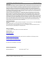
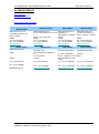
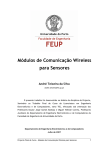
MTX-HSDPA-EU3 UMTS-HSDPA terminal modem
MTX-HSDPA-EU3
TERMINAL
Integrators Manual
Enhace your M2M
application into 3G
network
Powered by CINTERION EU3 HSDPA-UMTS Wireless Module
MTX-HSDPA-EU3 User Manual V.1.0
Pag. 1
Preliminary. Subject to change without prior notice
http://www.matrix.es
MTX-HSDPA-EU3 UMTS-HSDPA terminal modem
http://www.matrix.es
General Notes
Product is deemed accepted by recipient and is provided without interface to recipient’s products. The documentation and/or product
are provided for testing, evaluation, integration and information purposes. The documentation and/or product are provided on an “as
is” basis only and may contain deficiencies or inadequacies. The documentation and/or product are provided without warranty of any
kind, express or implied. To the maximum extent permitted by applicable law, Matrix Electronica further disclaims all warranties,
including without limitation any implied warranties of merchantability, completeness, fitness for a particular purpose and noninfringement of third-party rights. The entire risk arising out of the use or performance of the product and documentation remains
with recipient. This product is not intended for use in life support appliances, devices or systems where a malfunction of the product
can reasonably be expected to result in personal injury. Applications incorporating the described product must be designed to be in
accordance with the technical specifications provided in these guidelines. Failure to comply with any of the required procedures can
result in malfunctions or serious discrepancies in results.
Furthermore, all safety instructions regarding the use of mobile technical systems, including GSM products, which also apply to
cellular phones must be followed. Matrix Electronica or its suppliers shall, regardless of any legal theory upon which the claim is
based, not be liable for any consequential, incidental, direct, indirect, punitive or other damages whatsoever (including, without
limitation, damages for loss of business profits, business interruption, loss of business information or data, or other pecuniary loss)
arising out the use of or inability to use the documentation and/or product, even if Matrix Electronica has been advised of the
possibility of such damages. The foregoing limitations of liability shall not apply in case of mandatory liability, e.g. under the Spanish
Product Liability Act, in case of intent, gross negligence, injury of life, body or health, or breach of a condition which goes to the root
of the contract. However, claims for damages arising from a breach of a condition, which goes to the root of the contract, shall be
limited to the foreseeable damage, which is intrinsic to the contract, unless caused by intent or gross negligence or based on liability
for injury of life, body or health. The above provision does not imply a change on the burden of proof to the detriment of the
recipient. Subject to change without notice at any time. The interpretation of this general note shall be governed and construed
according to Spanish law without reference to any other substantive law.
Important information
This technical description contains important information for start up and use of the MTX-HSDPA-EU3
Terminal.
Read it carefully before you start working with the MTX-HSDPA-EU3 Terminal.
The warranty will be void should damage occur due to non-compliance with these instructions for use.
We cannot accept any responsibility for consequential loss.
Service and Support
To contact customer support please use the contact details below:
Matrix Electronica
Alejandro Sanchez, 109
28019 Madrid –[email protected]
Tel. +34915602737
Information about MTX-HSDPA-EU3 product and accessories is available on the following web site:
http://www.matrix.es/MTX-Terminals
FTP server: (ask for user & password)
ftp://ftp.matrixelectronica.eu/mtx-terminals/
Or contact your local distributor / sales agent:
REVISION INFORMATION
EDITION VERSION 1.0
First Release: April 8th, 2011
MTX-HSDPA-EU3 User Manual V.1.0
Pag. 2
Preliminary. Subject to change without prior notice
MTX-HSDPA-EU3 UMTS-HSDPA terminal modem
http://www.matrix.es
1. INTRODUCTION ..................................................................................................................................................... 5
1.1 Description ..................................................................................................................................5
1.2 Highlights ....................................................................................................................................6
1.3 Main Features and Services ..........................................................................................................7
1.3.1 Types of Mobile Station .................................................................................................................................. 7
1.3.2 Short Message Service .................................................................................................................................... 8
1.3.3 Voice Calls ..................................................................................................................................................... 9
1.3.4 Data ................................................................................................................................................................ 9
1.3.6 OPERATION MODES .................................................................................................................................... 9
1.3.7 Air Interface ................................................................................................................................................. 11
1.3.8 SIM Card ...................................................................................................................................................... 12
2. MECHANICAL DESCRIPTION .......................................................................................................................... 13
2.1 Overview................................................................................................................................... 13
2.2. Dimensions .............................................................................................................................. 14
3. ELECTRICAL DESCRIPTION ............................................................................................................................ 14
3. ELECTRICAL DESCRIPTION ............................................................................................................................ 15
3.1 Power Connector ....................................................................................................................... 15
3.2 Audio Connector ........................................................................................................................ 16
3.3 Mini USB Connector ................................................................................................................... 19
3.4 Antenna Connector .................................................................................................................... 19
3.5. SIM card reader........................................................................................................................ 19
3.6 Real Time Clock ......................................................................................................................... 21
3.7. Software Updates ..................................................................................................................... 22
4. OPERATION ........................................................................................................................................................... 23
4.1 Switching On the Modem ........................................................................................................... 23
4.2 Switching Off the Modem ........................................................................................................... 23
4.3 Operating States/LED ................................................................................................................ 23
5. EU3 AT COMMAND INTERPRETER ................................................................................................................ 24
6 SAFETY AND PRODUCT CARE .......................................................................................................................... 25
6.1.
6.2.
6.3.
6.4.
6.5.
6.6.
Safety instructions .................................................................................................................... 25
General precautions .................................................................................................................. 25
SIM card precautions ................................................................................................................ 25
Antenna precautions ................................................................................................................. 26
Radio Frequency (RF) exposure and SAR ................................................................................... 26
Personal Medical Devices .......................................................................................................... 26
7. INSTALLATION OF THE MODEM ................................................................................................................... 27
7.1 Where to install the modem ....................................................................................................... 27
7.1.1 Environmental conditions ............................................................................................................................. 27
7.1.2 Signal strength .............................................................................................................................................. 27
7.1.3 Connections of components to MTX-HSDPA-EU3 Terminal ....................................................................... 27
7.1.4 Network and Subscription ............................................................................................................................ 27
7.2 How to install the modem .......................................................................................................... 27
7.2.1 Power supply ................................................................................................................................................ 27
7.2.2 Securing the modem ..................................................................................................................................... 28
7.3 Antenna .................................................................................................................................... 28
7.3.1 General ......................................................................................................................................................... 28
7.3.2 Antenna type ................................................................................................................................................. 28
7.3.3 Antenna placement ....................................................................................................................................... 28
7.3.4 The antenna cable......................................................................................................................................... 28
7.3.5 Possible communications disturbances ........................................................................................................ 29
8. ACCESSORIES ....................................................................................................................................................... 30
MTX-HSDPA-EU3 User Manual V.1.0
Pag. 3
Preliminary. Subject to change without prior notice
MTX-HSDPA-EU3 UMTS-HSDPA terminal modem
http://www.matrix.es
8.1. POWER SUPPLY ........................................................................................................................ 30
8.1.1 AC Power Adaptor ....................................................................................................................................... 30
8.1.2 DC cable ....................................................................................................................................................... 30
8.2. ANTENNAS ............................................................................................................................... 31
8.2.1 Magnetic Dual Band Antenna (900/1800MHz) ............................................................................................ 31
8.2.3 Patch Adhesive Antenna ............................................................................................................................... 31
8.3. CABLES .................................................................................................................................... 32
8.3.1 USB CABLE ................................................................................................................................................. 32
9. CONFORMITY ASSESSMENT............................................................................................................................ 33
10. ROHS STATEMENT ............................................................................................................................................ 34
11. DISPOSAL OF OLD ELECTRICAL & ELECTRONIC EQUIPMENT (WEEE MARK) ........................... 34
12. ABBREVIATIONS................................................................................................................................................ 35
13. AT COMMAND SUMMARY .............................................................................................................................. 36
14. SALES CONTACT ............................................................................................................................................... 40
MTX-HSDPA-EU3 User Manual V.1.0
Pag. 4
Preliminary. Subject to change without prior notice
MTX-HSDPA-EU3 UMTS-HSDPA terminal modem
http://www.matrix.es
1. INTRODUCTION
1.1 Description
When your application needs to receive data up to 3.6 Mbps download or transmit up to 386Kbps, the
MTX-HSDPA-EU3 terminal is the solution based on HSDPA technology.
The HSPA (High Speed Downlink Packet Access) is a transmission standard based on the UMTS network
which allows a download speed of up to 3.6 Mbit/s. The technology therefore enables services like
broadband internet and e-mail access, high-speed download of large data files and streaming of videos or
music.
The MTX-HSDPA-EU3 is a complete terminal that encapsulates everything you need in one compact plugand-play unit. The integration is almost not needed because has its own SIM card reader and a USB port,
minimizing the need for further hardware components.
The MTX-HSDPA-EU3 is controlled via AT commands and standard interfaces such as USB 2.0 full speed
and NDIS driver.
When UMTS-HSDPA network operation is not present, the MTX-HSDPA-EU3 can operate in EDGE class 10
max. 236,8 kpbs (DL), max. 118 kbps (UL) or in GPRS class 10: max. 85.6 kbps (DL), max. 42.8 kbps (UL)
The MTX-HSDPA-EU3 can also work in simple CSD data transmission (GSM data rate 14.4 kpbs, V.110,
UMTS data rate 57.6 kpbs V.120) as well Short Messaging (SMS), and FAX specifications. It has also an
analogue interface and capable to make a voice communication call.
MTX-HSDPA-EU3 is manufactured with SMD Technologies with the ISO 9001 & IS0 14001
certifications and it is RoHs / WEEE compliant.
Quality
A full list of antennas, cables and supplies accessories are available.
The MTX-HSDPA-EU3 terminal is powered by an internal SIEMENS Wireless Module EU3
Note!.Some of the functions described inside this Technical Description are only possible when the SIMCard is inserted
ORDERING INFORMATION & VERSION
ORDERING CODE : 199.801.090
Hardware Release 2.01
Firmware Version: 01.014
Module inside: EU3-E
MTX-HSDPA-EU3 User Manual V.1.0
Pag. 5
Preliminary. Subject to change without prior notice
MTX-HSDPA-EU3 UMTS-HSDPA terminal modem
http://www.matrix.es
1.2 Highlights
General features:
Specification for HSDPA data transmission:
• HSDPA: max. 3.6 Mbps (DL),
• HSDPA 3.6 Mbps
max. 384 kbps (UL)
•Tri-Band UMTS/HSDPA(WCDMA/FDD) 850/1900/2100 MHz • UE CAT [1-6], 11, 12 supported
• Compressed mode according to 3GPP TS25.212
•Quad-Band GSM 850/900/1800/1900 MHz
• EDGE (E-GPRS) multi-slot class 10
• GPRS multi-slot class 10
Specification for UMTS data transmission:
• UMTS/HSDPA 3GPP release 5
• UMTS: max. 384 kbps (DL),
• GSM 3GPP release 99
max. 384 kbps (UL)
• Output power:
- Class 4 (2 W) for GSM900
Specification for EDGE data transmission:
- Class 3 (0.25 W) for UMTS
• EDGE class 10: max. 236,8 kpbs (DL),
- Class E2 (0.5 W) for EDGE900
max. 118 kbps (UL)
- Class E2 (0.4 W) for EDGE1800
• Mobile station class B
- Class 1 (1 W) for GSM1800
• Modulation and coding écheme MCS 1-9
• Control via AT commands
(Hayes 3GPP TS 27.007 and 27.005)
Specification for GPRS data transmission:
• Power consumption:
• GPRS class 10: max. 85.6 kbps (DL),
- Power down 50 μA
max. 42.8 kbps (UL)
- Average Supply Current < 970mA
• Mobile station class B
(HSDPA data transfer)
• Full PBCCH support
• Temperature range
• Coding schemes CS 1-4
- Normal Operation: -30°C to +65°C
- Restricted Operation: -30°C to +75°C
Specification for CSD data transmission:
- Storage: -40°C to +85°C
• GSM data rate 14.4 kpbs, V.110
• Dimensions. Excluding connectors: 78,1 x 66,8 x 37,2 mm • UMTS data rate 57.6 kpbs V.120
• Weight: < 190 g
• RLP (Non-transparent mode)
• Supply voltage range: 6 ... 30 V
Interfaces:
FME M 50 Ohm antenna connector
USB 2.0 full speed interface
Operating status LED bi-color
SIM card interface 3 V, 1.8 V
Plug-in power supply and on/off interfaces
• Handset audio interface
•
•
•
•
•
Specification for SMS:
• Point-to-point MO and MT
• SMS cell broadcast
• Text and PDU mode
Specification for voice:
• Triple-rate codec for HR, FR and EFR
• GSM & 3GPP: Adaptive multi-rate AMR
• DTMF supported
• CEPT supervisory tones supported
Special features:
• Improved power-saving modes
• NDIS/USB driver for Microsoft® Windows® XP
• Customer IMEI as variant
• Firmware update via USB
MTX-HSDPA-EU3 User Manual V.1.0
Pag. 6
Preliminary. Subject to change without prior notice
MTX-HSDPA-EU3 UMTS-HSDPA terminal modem
http://www.matrix.es
1.3 Main Features and Services
The MTX-HSDPA-EU3 performs a set of telecom services (TS) according to GSM standard phase 2+, ETSI
and ITU-T. The services and functions of the MTX-HSDPA-EU3 are implemented by AT commands issued
over the USB interface.
1.3.1 Types of Mobile Station
The MTX-HSDPA-EU3 is a UMTS/HSDPA and also GSM/GPRS bands mobile station with the characteristics
shown in the table below.
Feature
Implementation
General
Frequency bands
Dual-Band UMTS/HSDPA (WCDMA/FDD) 900/2100 MHz
Dual-Band GSM 850/900/1800/1900 MHz
GSM class
Small MS
Output power (according to
Release 99)
Class
Class
Class
Class
Class
Power supply
5V < VCC < 32V
Physical
Dimensions: 78,1 x 66,8 x 37,2 mm Weight: approx. 190g
RoHS
All hardware components fully compliant with EU RoHS Directive
4 (+33dBm ±2dB) for EGSM900
1 (+30dBm ±2dB) for GSM1800
E2 (+27dBm ± 3dB) for GSM 900 8-PSK
E2 (+26dBm +3 /-4dB) for GSM 1800 8-PSK
3 (+24dBm +1/-3dB) for UMTS 2100, WCDMA FDD BdI
HSDPA features
3GPP Release 5
3.6 Mbps, UL 384 kbps UE CAT. [1-6], 11, 12 supported Compressed mode
(CM) supported according to 3GPP TS25.212
UMTS features
3GPP Release 4
PS data rate – 384 kbps DL / 384 kbps UL
CS data rate – 64 kbps DL / 64 kbps UL
GSM / GPRS / EGPRS features
Data transfer
GPRS
EGPRS
CSD
•
•
•
•
Multislot Class 10
Full PBCCH support
Mobile Station Class B
Coding Scheme 1 – 4
•
•
•
•
•
•
•
•
•
•
•
•
Multislot Class 10
EDGE E2 power class for 8 PSK
Downlink coding schemes – CS 1-4, MCS 1-9
Uplink coding schemes – CS 1-4, MCS 1-9
BEP reporting
SRB loopback and test mode B
8-bit, 11-bit RACH
PBCCH support
1 phase/2 phase access procedures
Link adaptation and IR
NACC, extended UL TBF
Mobile Station Class B
• V.110, RLP, non-transparent
• 9.6 kbps
MTX-HSDPA-EU3 User Manual V.1.0
Pag. 7
Preliminary. Subject to change without prior notice
MTX-HSDPA-EU3 UMTS-HSDPA terminal modem
http://www.matrix.es
Feature
Implementation
SMS
Point-to-point
MT and MO Cell broadcast
Text and PDU mode
Audio
Audio speech codecs
GSM: AMR, EFR, FR, HR
3GPP: AMR
One ringing melody supported
CEPT supervisory tones supported
DTMF supported
6 audio modes: Approval, Router, Handset, Headset, Speakerphone and
Transparent mode
9 ringing melodies supported
CEPT and ANSI supervisory tones supported
Software
AT commands
AT-Hayes GSM 07.05 and 07.07, Siemens
AT commands for RIL compatibility (NDIS/RIL)
MicrosoftTM compatibility
RIL / NDIS / USB drivers for Windows MobileTM
SIM Application Toolkit
SAT Class C
Firmware update
Firmware update from host application over USB.
Interfaces
USB
Supports a USB 2.0 Full Speed (12Mbit/s) device interface.
Wakeup Control
Signal pin to wake up an inactive USB Host into an active state.
Status
Bi-colour LED to indicate network connectivity status.
Audio
1 analog interface
UICC interface
Supported chip cards: SIM / UICC 3V, 1.8V
Antenna
50 Ohms. External antenna can be connected via FME M antenna connector
Module interface
Mini USB-B connector
Power on/off, Reset
Power on/off
Switch-on by hardware pin TURN_ON
Switch-off by hardware pin TURN_OFF
Switch-off by AT command
Reset
Orderly shutdown and reset by AT command
Emergency off
Emergency off by hardware pin TURN_OFF
1.3.2 Short Message Service
The wireless modem supports the following SMS services:
• Sending; MO (mobile-originated) with both PDU (protocol data unit) and text mode supported
• Receiving; MT (mobile-terminated) with both PDU and text mode supported
• CBM (cell broadcast message); a service in which a message is sent to all subscribers located in one or more
specific cells in the GSM network (for example, traffic reports)
• SMS status report according to 3GPP TS 23.40
MTX-HSDPA-EU3 User Manual V.1.0
Pag. 8
Preliminary. Subject to change without prior notice
MTX-HSDPA-EU3 UMTS-HSDPA terminal modem
http://www.matrix.es
1.3.3 Voice Calls
The wireless modem offers the capability of MO (mobile originated) and MT (mobile terminated) voice calls, as
well as supporting emergency calls. Multi-party, call waiting and call divert features are available. Some of these
features are network operator specific.
For the inter-connection of audio, the wireless modem offers balanced analogue input and output lines. The
wireless modems support HR, FR, EFR and AMR vocoders.
1.3.4 Data
The wireless modem supports the following data protocols:
• HSDPA: 3.6 Mbps DL / 384 kbps UL
• UMTS 384 kbps DL / 384 kbps UL
• GPRS (General Packet Radio Service)
The wireless modem is a Class B terminal, multislot class 10.
•
•
EGPRS Multislot Class 10
CSD (Circuit Switched Data) 9.6 kbps
1.3.5 OPERATION MODES
The table below briefly summarizes the various operating modes referred to in the following chapters.
Mode
Function
Normal
operation
GSM / GPRS / UMTS /
HSDPA SLEEP
Power saving mode set automatically when no call is in progress and the
USB connection is suspended by host or not present.
GSM IDLE
Software is active. Once registered to the GSM network, paging with BTS is
carried out in order to achieve synchrony with the GSM network. The
repetition rate depends on the parameter BSPA_Multiframe. The module is
ready to send and receive.
GSM TALK/ GSM DATA
Connection between two subscribers is in progress. Power consumption
depends on the GSM network coverage and several connection settings
(e.g. DTX off/on, FR/EFR/HR, hopping sequences and antenna connection).
The following applies when power is to be measured in TALK_GSM mode:
DTX off, FR and no frequency hopping, otherwise same as for IDLE
measurements.
GPRS IDLE
Module is attached and ready for GPRS data transfer, but no data is
currently sent or received.
GPRS DATA
GPRS data transfer in progress. Power consumption depends on net-work
settings (e.g. power control level), uplink / downlink data rates and GPRS
configuration (e.g. used multislot settings).
EGPRS DATA
EGPRS data transfer in progress. Power consumption depends on net-work
settings (e.g. power control level), uplink / downlink data rates and EGPRS
configuration (e.g. used multislot settings).
UMTS / HSDPA IDLE
Module is attached and ready for UMTS / HSDPA data transfer, but no data
is currently sent or received.
UMTS TALK/ UMTS
DATA
UMTS data transfer in progress. Power consumption depends on net-work
settings (e.g. TPC Pattern) and data transfer rate.
HSDPA DATA
HSDPA data transfer in progress. Power consumption depends on net-work
settings (e.g. TPC Pattern) and data transfer rate.
Power
Down
The internal power section is shut down. The SW on the module is not active. The interfaces are not
accessible.
MTX-HSDPA-EU3 User Manual V.1.0
Pag. 9
Preliminary. Subject to change without prior notice
MTX-HSDPA-EU3 UMTS-HSDPA terminal modem
http://www.matrix.es
Average power consumption
P aram eter
IBATT+
Description
Conditions
OFF State supply
current
POWER DOWN
50
μA
SLEEP (USB Suspend) @DRX=9
2.2
mA
SLEEP (USB Suspend) @DRX=5
2.7
mA
SLEEP (USB Suspend) @DRX=2
3.9
mA
IDLE (USB active) @DRX=2
70
mA
Voice Call GSM900; PCL=5
290
mA
GPRS Data transfer GSM900; PCL=5; 1Tx/4Rx
310
mA
GPRS Data transfer GSM900; PCL=5; 2Tx/3Rx
410
mA
EDGE Data transfer GSM900; PCL=5; 1Tx/4Rx
250
mA
EDGE Data transfer GSM900; PCL=5; 2Tx/3Rx
300
mA
Voice Call GSM1800; PCL=0
240
mA
GPRS Data transfer GSM1800; PCL=0; 1Tx/4Rx
270
mA
GPRS Data transfer GSM1800; PCL=0; 2Tx/3Rx
340
mA
EDGE Data transfer GSM1800; PCL=0; 1Tx/4Rx
230
mA
EDGE Data transfer GSM1800; PCL=0; 2Tx/3Rx
280
mA
VOICE Call GSM900; PCL=5
1.95
2.7
A
VOICE Call GSM1800; PCL=0
1.2
2.1
A
SLEEP (USB Suspend) @DRX=9
2.0
mA
SLEEP (USB Suspend) @DRX=8
2.4
mA
SLEEP (USB Suspend) @DRX=6
3.7
mA
Idle (USB active) @ DRX=6
70
mA
UMTS Data transfer Band I @+23dBm
650
HSDPA Data transfer Band I @+23dBm
610
mA
UMTS Data transfer Band VIII @+23dBm
630
mA
HSDPA Data transfer Band VIII @+23dBm
640
Average GSM /
GPRS supply
current1
Peak current during GSM transmit
burst
IBATT+
Average WCDMA
supply current
1. With
an impedance of ZLOAD=50Ohm at the antenna connector
neighbouring cells; without t3212 timer occurance
3. Under total mismatch conditions at antenna connector
2. Without
MTX-HSDPA-EU3 User Manual V.1.0
Pag. 10
Preliminary. Subject to change without prior notice
M in
Typ
M ax
750
740
Unit
mA
mA
MTX-HSDPA-EU3 UMTS-HSDPA terminal modem
http://www.matrix.es
1.3.6 Air Interface
Parameter
Conditions
HSDPA / UMTS
connectivity
UMTS Frequency range
Uplink (UE to Node B)
Band I, VIII
UMTS Frequency range
Downlink (Node B to UE)
Receiver Input Sensitivity
@ ARP
RF Power@ ARP with
50Ohm Load
Min.
Typical
Max.
Unit
UMTS 900 Band VIII
880
915
MHz
UMTS 2100 Band I
1920
1980
MHz
UMTS 900 Band VIII
1930
1990
MHz
UMTS 2100 Band I
2110
2170
MHz
UMTS 850 Band V
-109
dBm
UMTS 1900 Band II
-107
dBm
UMTS 2100 Band I
-108
dBm
UMTS 850 Band V
+21
+23
+25
dBm
UMTS 1900 Band II
+21
+23
+25
dBm
UMTS 2100 Band I
+21
+23
+25
dBm
GPRS coding schemes
Class 10, CS1 to CS4
EGPRS
Class 10, MCS1 to MCS9
GSM Class
Small MS
GSM Frequency range
Uplink (MS to BTS)
GSM 850
824
849
MHz
E-GSM 900
880
915
MHz
GSM 1800
1710
1785
MHz
GSM 1900
1850
1910
MHz
GSM 850
869
894
MHz
E-GSM 900
925
960
MHz
GSM 1800
1805
1880
MHz
GSM 1900
1930
1990
MHz
GSM 850
-102
-108
dBm
E-GSM 900
-102
-108
dBm
GSM 1800
-102
-107
dBm
GSM 1900
-102
-107
dBm
E-GSM 900
31
32
35
dBm
GSM 1800
28
29.25
32
dBm
GSM 1900
28
29.25
32
dBm
GSM Frequency range
Downlink (BTS to MS)
Static Receiver input
Sensi-tivity @ ARP
MTX-HSDPA-EU3 User Manual V.1.0
Pag. 11
Preliminary. Subject to change without prior notice
MTX-HSDPA-EU3 UMTS-HSDPA terminal modem
http://www.matrix.es
Parameter
Conditions
Min.
Typical
Max.
Unit
RF Power@ ARP with
50Ohm Load (GSM; 1 TX)
RF Power@ ARP with
50Ohm Load (GPRS; 1
TX)
GSM 850
31
32
35
dBm
RF Power@ ARP with
50Ohm Load (EGPRS; 1
TX)
RF Power@ ARP with
50Ohm Load (GPRS; 2
TX)
RF Power@ ARP with
50Ohm Load (EGPRS; 2
TX)
GSM 850
32
dBm
E-GSM 900
32
dBm
GSM 1800
29.25
dBm
GSM 1900
29.25
dBm
GSM 850
27
dBm
E-GSM 900
27
dBm
GSM 1800
26
dBm
GSM 1900
26
dBm
GSM 850
30.50
dBm
E-GSM 900
30.50
dBm
GSM 1800
27.75
dBm
GSM 1800
27.75
dBm
GSM 850
25
dBm
E-GSM 900
25
dBm
GSM 1800
24
dBm
GSM 1900
24
dBm
1.3.8 SIM Card
The MTX-HSDPA-EU3 supports an external SIM card through the integrated SIM holder. Both 3V and
1.8V SIM technology is supported. Older, 5V SIM technology is not supported
MTX-HSDPA-EU3 User Manual V.1.0
Pag. 12
Preliminary. Subject to change without prior notice
MTX-HSDPA-EU3 UMTS-HSDPA terminal modem
http://www.matrix.es
2. MECHANICAL DESCRIPTION
2.1 Overview
The pictures below show the mechanical design of the module along with the positions of the different
connectors and mounting holes. The module case is made of durable PC/ABS plastic.
MTX-HSDPA-EU3 User Manual V.1.0
Pag. 13
Preliminary. Subject to change without prior notice
MTX-HSDPA-EU3 UMTS-HSDPA terminal modem
2.2. Dimensions
Figure 5. Dimensions of the MTX-HSDPA-EU3 terminal in mm
MTX-HSDPA-EU3 User Manual V.1.0
Pag. 14
Preliminary. Subject to change without prior notice
http://www.matrix.es
MTX-HSDPA-EU3 UMTS-HSDPA terminal modem
http://www.matrix.es
3. ELECTRICAL DESCRIPTION
All electrical connections to the module are protected in compliance with the standard air and contact
Electrostatic Discharge (ESD).
The module uses the following industry standard connectors:
• USB port
• RJ12 6-way (power supply connector)
• RJ12 4-way (handset connector)
• SIM card reader
• FME male coaxial jack (antenna connector)
3.1 Power Connector
An RJ12 6-way connector, as shown and described below, serves means of supplying and controlling d.c.
power to the modem.
The supply voltage, VCC, required by the modem is in the range 6-32V d.c. The power supply has to be a
single voltage source of POWER=6V…30V capable of providing a peak during an active transmission. The
uplink burst causes strong ripples (drop) on the power lines.
Application of the supply voltage does not switch the modem on. To do so an additional active-high control
signal, TURN_ON, must applied for > 0.2s.
A second active-high control signal, TURN_OFF, can be used to switch modem off when applied for 1 - 2
seconds, or can be used to perform hardware reset when applied for > 3.5s.
PI N :
Signal
Dir
Lim its
Description
6 - 32 V DC
Positive power input
1
VCC
Input
2
Not connected
-
3
TURN_OFF
Input
4
TURN_ON
Input
5
VDDLP
I/O
6
GND
Input
6 – 32 V
6 – 32 V
Active high control line used to switch off or
reset the modem
VIH > 5V, VIL < 2V
Power off: t >10ms
Active high control line used to switch on the
modem
VIH > 5V, VIL < 2V
Power on: t > 0.2s
Backup the RTC from an external capacitor or a
battery (rechargeable or non-chargeable).
Negative power (ground)
Note. VCC and GND are reverse polarity and overvoltage protected.
MTX-HSDPA-EU3 User Manual V.1.0
Pag. 15
Preliminary. Subject to change without prior notice
MTX-HSDPA-EU3 UMTS-HSDPA terminal modem
http://www.matrix.es
3.2 Audio Connector
A 6-way 4-poles RJ connector, as shown below, allows a telephone handset to be plugged into the
modem, giving access to the microphone and earpiece signals. The connector may also be used to drive
other analogue audio sub-systems or devices.
The audio interface provides one analog input for a microphone and one analog output for an earpiece.
• The microphone input and the earpiece output are balanced.
• For electret microphones a supply source is implemented.
• The MTX-HSDPA-EU3 is pre-configured to work with a range of handsets, the audio interface is flexible
and its performance can be configured, using AT commands, to match a particular handset or audio
subsystem.
Audio handset connection.
Audio signal descriptions are listed below:
P in
Signal
Dir
Description
0
Not connected
1
MICN
I
2
EPN
O
3
EPP
O
4
MICP
I
Microphone
negative input
Earpiece
negative
output
Earpiece
positive
output
Microphone positive
input
5
Not connected
A power supply for electret microphones is already feeded to MICP connection.
Microphone signals are fed via the MICP and MICN pins to an analog-to-digital converter (ADC) and the
DSP. The DSP application core calculates e.g. digital gains, sidetone, echo cancellation or noise
suppression depending on the current configuration of the audio path. The processed speech samples are
passed to the speech encoder.
Received samples from the speech decoder are passed to the digital-to-analog converter (DAC) after post
processing (frequency response correction, adding sidetone etc.). The loudspeaker signal is routed via EPP
and EPN pins.
In order to support different types of equipment, the audio interface can be configured with different
audio modes via the AT^SNFS command. The electrical characteristics of the voiceband part vary with the
audio mode. For example, sending and receiving amplification, sidetone paths, noise suppression etc.
depend on the selected mode and can be set with AT commands.
The default audio mode (AT^SNFS=1) is intended to be used with the audio interface. This
default configuration is optimized for the Votronic HH-SI-30.3/V1.1/0 handset and used for type
approving the Siemens reference configuration. Audio mode 1 has fixed parameters that cannot
MTX-HSDPA-EU3 User Manual V.1.0
Pag. 16
Preliminary. Subject to change without prior notice
MTX-HSDPA-EU3 UMTS-HSDPA terminal modem
http://www.matrix.es
be modified.
3.3 MAIN Serial RS232 Interface Port
ASC0
The modem supports a standard RS232 serial interface (EIA/TIA 574) via its 9 pin Sub-D connector,
shown below.
MTX-HSDPA-EU3 Terminal is designed for use as a DCE. (data circuit-terminating equipment) based on the
conventions for DCE-DTE connections it communicates with the customer application (DTE- data
terminating equipment) using the following signals:
• Port TxD @ application sends data to TXD of MTX-63I/65I Terminal
• Port RxD @ application receives data from RXD of MTX-63I/65I Terminal
The RS-232 interface is implemented as a serial asynchronous transmitter and receiver conforming to ITUT V.24 Interchange Circuits DCE. It is configured for 8 data bits, no parity and 1 stop bit and can be
operated at fixed bit rates from 300bps to 460,800bps.
Autobauding supports bit rates from 1,2bps to 460,800bps. Hardware handshake using the /RTS and /CTS
signals and XON/XOFF software flow control are supported.
In addition the modem control signals DTR, DSR, DCD and RING are available. The MODEM control signal
RING (Ring Indication) can be used to indicate, to the cellular device application, that a call or Unsolicited
Result Code (URC) is received.
The electrical characteristics of the serial port signals are shown below:
Note: Outputs at 3kOhm load
P in
Signal
Dir
Voltage
levels
Description
1
DCD
O
Min ±5V
Data carrier detect
2
RD 0
O
Min ±5V
Received data
3
TD 0
I
4
DTR
I
5
GND
-
0V
Ground connection
6
DSR
O
Min ±5V
Data set ready
7
RTS
I
VILmax = 0.6V
VIHmin = 2.4V
VImax = ±25V
Request to send
8
CTS
O
Min ±5V
Clear to send
VILmax = 0.6V
VIHmin = 2.4V
VImax = ±25V
VILmax = 0.6V
VIHmin = 2.4V
VImax = ±25V
MTX-HSDPA-EU3 User Manual V.1.0
Pag. 17
Preliminary. Subject to change without prior notice
Transmitted data
Data terminal ready
MTX-HSDPA-EU3 UMTS-HSDPA terminal modem
9
RI
O
http://www.matrix.es
Min ±5V
Ring indicator
Features
• Includes the data lines TXD0 and RXD0, the status lines RTS0 and CTS0 and, in addition, the modem
control lines DTR0, DSR0, DCD0 and RING0.
• ASC0 is primarily designed for controlling the GSM engine with AT commands.
• Full Multiplex capability allows the interface to be partitioned into three virtual channels, yet with CSD
and fax services only available on the first logical channel.
• The DTR0 signal will only be polled once per second from the internal firmware of MTX-63I/65I.
• The RING0 signal serves to indicate incoming calls and other types of URCs (Unsolicited Result Code). It
can also be used to send pulses to the host application, for example to wake up the application from
power saving state. To configure the RING0 line use following AT Command: AT^SCFG.
• By default, configured for 8 data bits, no parity and 1 stop bit. The setting can be changed using the AT
command AT+ICF and, if required, AT^STPB. .
• ASC0 can be operated at fixed bit rates from 300 bps to 460800 bps.
• By default, serial speed is 115200bps
• Autobauding is not compatible with multiplex mode.
• Supports RTS0/CTS0 hardware flow control and XON/XOFF software flow control.
3.7 Expansion I/O port
MTX-HSDPA includes expansion Input/Outputs port on the 15 pin high density connector. The MTX-65I
supports a range of configurable I/Os plus SPI bus.
1.
2.
3.
4.
5.
MTX-HSDPA-EU3 User Manual V.1.0
Pag. 18
Preliminary. Subject to change without prior notice
Do not use
Not connected
TD1
GPIO 1
GPIO 3
6. Do not use
7. Not connected
8. Not connected
9. Vout
10. Do not use
11.
12.
13.
14.
15.
GPIO 2
GPIO 4
ADC 2
GND
ADC 1
MTX-HSDPA-EU3 UMTS-HSDPA terminal modem
http://www.matrix.es
3.3 Mini USB Connector
The USB 2.0 interface allows the connectivity to all relevant PCs and control boards in office and industrial
environments. The USB interface is a USB 2.0 full speed (12Mbit/s) interface for AT-C modem functionality
between the MTX-HSDPA-EU3 Terminal and a host controller e.g. a PC.
It can be operated on a USB 2.0 Full Speed or High Speed root hub (a PC host), but not on a generic USB
2.0 High Speed hub which translates High Speed (480 Mbit/s/) to Full Speed (12 Mbit/s).
The USB I/O-pins are capable of driving the signal at min 3.0V. They are 5V I/O compliant. To properly
connect the module’s USB interface to the host a USB 2.0 compatible connector is required. Furthermore,
the USB modem driver delivered with MTX-HSDPA-EU3 must be installed as described below.
The USB cannot be used as power supply of MTX-HSPA-EU3 terminal. It is mandatory to use an external
power supply for MTX-HSDPA-EU3. See accessories section.
3.4 Antenna Connector
The antenna connector allows transmission of radio frequency (RF) signals between the modem and an
external customer-supplied antenna. The modem is fitted with a 50Ω, FME male coaxial jack.
The external antenna must be matched properly to achieve best performance regarding radiated power,
DC-power consumption, modulation accuracy and harmonic suppression.
3.5. SIM card reader
The MTX-HSDPA-EU3 Terminal is fitted with a SIM card reader designed for 1.8V and 3V SIM cards. It is
the flip-up type which is lockable in the horizontal position and is accessed through a removable panel as
shown below.
MTX-HSDPA-EU3 User Manual V.1.0
Pag. 19
Preliminary. Subject to change without prior notice
MTX-HSDPA-EU3 UMTS-HSDPA terminal modem
http://www.matrix.es
The card holder is a five wire interface according to GSM 11.11. It has a SIM card detector switch to
detect whether or not the SIM card drawer is inserted.
Removing and inserting the SIM card during operation requires the software to be reinitialized. Therefore,
alter reinserting the SIM card it is necessary to restart MTX-HSDPA-EU3 Terminal.
The full operation of the MTX-HSDPA-EU3 relies on a SIM card being inserted. Some MTX-HSDPA-EU3
functionality may be lost if you try to operate the control terminal without a SIM card.
MTX-HSDPA-EU3 User Manual V.1.0
Pag. 20
Preliminary. Subject to change without prior notice
MTX-HSDPA-EU3 UMTS-HSDPA terminal modem
http://www.matrix.es
3.6 Real Time Clock
The MTX-HSDPA-EU3 contains a real time clock (RTC) to maintain accurate timekeeping and to enable
“time stamping” of messages.
The RTC could be powered with the signal VRTC present in pin 5 of the POWER CONNECTOR. See section
3.1.
The user must connect this pin to an external energy device like a battery or super-capacitor to provide
back-up power to maintain the RTC. Example: If using a 300mF supercap the RTC can be maintain for at
least 12 hours.
The internal Real Time Clock of MTX-HSDPA-EU3 is supplied from a separate voltage regulator in the
analog controller which is also active when MTX-HSDPA-EU3 is in POWER DOWN status.
In addition, you can use the VRTC pin on the connector to backup the RTC from an external capacitor or a
battery (rechargeable or non-chargeable). The capacitor is charged by the BATT+ line of internal EU3. If
the voltage supply at BATT+ is disconnected the RTC can be powered by the capacitor.
The size of the capacitor determines the duration of buffering when no voltage is applied to MTX-HSDPAEU3, i.e. the larger the capacitor the longer MTX-HSDPA-EU3 will save the date and time. A serial 1kΩ
resistor placed on the board next to VDDLP limits the charge current of an empty capacitor or battery.
The following figures show various sample configurations.
The MTX-HSDPA-EU3 can accommodate this battery or super-cap inside, and the MTX-HSDPA-EU3 can be
ordered with this special option by request. Please contact [email protected] about this request.
MTX-HSDPA-EU3 User Manual V.1.0
Pag. 21
Preliminary. Subject to change without prior notice
MTX-HSDPA-EU3 UMTS-HSDPA terminal modem
3.7. Software Updates
It is possible and sometimes necessary to update the MTX-HSDPA-EU3 software.
Updates must be carried out by an approved technician.
Please contact your supplier for details Service/Programming
MTX-HSDPA-EU3 User Manual V.1.0
Pag. 22
Preliminary. Subject to change without prior notice
http://www.matrix.es
MTX-HSDPA-EU3 UMTS-HSDPA terminal modem
http://www.matrix.es
4. OPERATION
4.1 Switching On the Modem
There is ONE way to switch on the modem, once power is applied:
• assert TURN_ON high for > 0.4s;
The modem is fully operational after 4 seconds. Logging onto a network may take longer than this and is
outside the control of the modem.
The modem can be configured to start up at the time power is applied by permanently tying power
connector signals TURN_ON (pin 4) and VCC (pin 1) together.
4.2 Switching Off the Modem
There are 2 ways to switch off (power down) the modem as described below:
• Either use the AT^SMSO command; RECOMMENDED.
The AT^SMSO command lets the MTX-HSDPA-EU3 Terminal log off from the network and allows the
software to enter into a secure state and safe data before disconnecting the power supply. The mode is
referred to Power-down mode. In this mode only the RTC stays active.
• Or assert TURN_OFF, pin 3 of power supply connector, high for >1 seconds. A delay of up to 10s is
experienced as the modem logs off the network.
4.3 Operating States/LED
The modem has a dual color LED, which displays the operating status of the Terminal. Both LEDS are
provided for signalling the module’s network connectivity status -STATUS0 to signal the GSM connectivity
and STATUS1 to signal the UMTS connectivity.
This status function has to be activated with AT^SLED=1. This command is VOLATILE; it lost the
configuration when terminal is shut down. Please ensure to write it at configuration & initialization string.
In following table is showed the different operating status of the LEDS:
GREEN LED connected to STATUS0 line:
• Lights steadily when the ME is registered to the GSM network and either awake or in power
saving state.
• Flashes at 1Hz and 50% duty cycle (0.5s on, 0.5s off) when the ME is awake and not registered
to any network.
• Flashes at 0.25 Hz and appr. 50% duty cycle (2s on, 2s off) when the ME is in power saving
state and not registered to any network.
When the ME is in power saving state and not registered, the flashing frequency may be less than
0.25Hz and the duty cycle may vary, for example between 45% and 55%. These variations are
due to transitions from awake state to power saving state which may occur at the beginning of an
LED flashing period (eg. at the beginning of a 1Hz or 0.25Hz flashing period). In the worst case,
the LED will indicate a transition from awake to power saving after 4s.
• While the STATUS0 signal is active the STATUS1 signal is inactive.
YELLOW LED connected to STATUS1 line:
• Lights steadily when the ME is registered to the UMTS network.
• Is off when the ME is not registered to the UMTS network.
• While the STATUS1 signal is active the STATUS0 signal is inactive.
MTX-HSDPA-EU3 User Manual V.1.0
Pag. 23
Preliminary. Subject to change without prior notice
MTX-HSDPA-EU3 UMTS-HSDPA terminal modem
http://www.matrix.es
5. EU3 AT COMMAND INTERPRETER
After successful installation of the EU3 driver package, the physical USB interface of the module is
represented in the operating system by two virtual interfaces, each assigned to a virtual COM port of its
own:
• Modem interface:
This interface is referred to as "Modem" if queried with AT^SQPORT. In the quick reference tables it is
named USB0-MDM. In Windows XP, it will show up as "Siemens HSDPA USB Modem" in the Windows
Device Manager, under Modems. The COM port number automatically assigned by Windows during the
installation can be gathered from the Modems property page.
The modem interface is intended particularly for data transmission (HSDPA, GPRS, CSD or FAX)
established over a dial-up connection. Using AT commands on this interface is not recommended, except
for data call related commands like ATD or ATO.
URCs relevant for data calls (RING, NO CARRIER) are issued on the modem interface, all other URCs
normally only on the application interface.
• Application interface:
This port is referred to as "Application" if queried with AT^SQPORT. In the quick reference tables it is
named USB0-APP. In Windows XP, it will show up as "Siemens HSDPA USB Com Port" in the Windows
Device Manager, under Ports (COM&LPT), along with the COM port number automatically assigned by
Windows.
The application interface is designed especially for controlling the EU3, i.e. for entering AT commands,
receiving URCs, or sending and receiving short messages. It cannot be used as data interface for HSDPA,
GPRS, CSD or FAX.
Please note that URCs are normally indicated only on this interface, no matter which of the two interfaces
was used to send the AT commands for activating their presentation. This URC management scheme is
the default configuration recommended for a typical MTX-HSDPA-EU3 application.
If you need to operate the MTX-HSDPA-EU3 from both interfaces at a time, bear in mind that both are
handled by the same AT command interpreter. As a result, AT commands entered on both interfaces are
not executed in parallel but sequentially, one after the other. So, an AT command issued on one interface
will be buffered on this interface to be executed after the other interface has completed processing earlier
AT command(s). The buffered command string is not echoed, but will be indicated when executed.
When a dial-up connection is established over the modem interface, the application interface can be used
simultaneously for any control functions. This eliminates the need for the user to enter AT commands,
such as +++ and ATO, to switch back and forth between command and online mode when working on
one interface only. Yet, it should be noted that the dial-up connection disables the echo on both
interfaces, due to the initialization strings typically set by modems. The echo can be re-activated by
executing ATE1.
MTX-HSDPA-EU3 User Manual V.1.0
Pag. 24
Preliminary. Subject to change without prior notice
MTX-HSDPA-EU3 UMTS-HSDPA terminal modem
http://www.matrix.es
6 SAFETY AND PRODUCT CARE
Please read the information in this section and the information in “Installation of the
Modem”, before starting your integration work!
6.1. Safety instructions
PLEASE READ THESE SAFETY INSTRUCTIONS AND KEEP A COPY OF THEM.
• Always ensure that use of the modem is permitted. The modem may present a hazard if used in
proximity to personal medical electronic devices. As a rule, the modem must not be used in hospitals,
airports or planes.
• Never use the modem at a gas station, refueling point, blasting area or in any other environment where
explosives may be present.
• Operating the modem close to other electronic devices, such as antennas, television sets, and radios
may cause electromagnetic interference.
• This product is intended to be used with the antenna or other radiating element at least 20cm away from
any part of the human body. In applications where this rule cannot be applied, the application designer is
responsible for providing the SAR measurement test report and declaration.
• You are responsible for observing your country's safety standards, and where applicable, the relevant
wiring rules.
6.2. General precautions
The MTX-HSDPA-EU3 Terminal as a stand alone item is designed for indoor use only. To use outside it
must be integrated into a weatherproof enclosure. Do not exceed the environmental and electrical limits as
specified in “Technical Data”.
• Avoid exposing the modem to lighted cigarettes, naked flames or to extreme hot or cold temperature.
• Never try to dismantle the modem yourself. There are no components inside the modem that can be
serviced by the user. If you attempt to dismantle the modem, you may invalidate the warranty.
• The MTX-HSDPA-EU3 Terminal must not be installed or located where the surface temperature of the
plastic case may exceed 85°C.
• All cables connected to the MTX-HSDPA-EU3 Terminal must be secured or clamped, immediately
adjacent to the modem's connectors, to provide strain relief and to avoid transmitting excessive vibration
to the modem in the installation
• Ensure the d.c. cable, supplying power to the MTX-HSDPA-EU3 Terminal, does not exceed 3 meters.
• To protect power supply cables and meet the fire safety requirements when the unit is powered from a
battery or a high current supply, connect a fast 1.25A fuse in line with the positive supply.
• Do not connect any incompatible component or product to the MTX-HSDPA-EU3 Terminal.
Note! MTX-HSDPA-EU3 distributors and sales offices may refuse warranty claims where evidence of
product misuse is found.
6.3. SIM card precautions
Before handling the SIM card in your application, ensure that you are not charged with static electricity.
Use proper precautions to avoid electrostatic discharges.
MTX-HSDPA-EU3 User Manual V.1.0
Pag. 25
Preliminary. Subject to change without prior notice
MTX-HSDPA-EU3 UMTS-HSDPA terminal modem
http://www.matrix.es
• When the SIM card hatch is opened, the SIM card connectors lie exposed under the SIM card holder.
Caution! Do not touch these connectors! If you do, you may release an electrical discharge that could
damage the modem or the SIM card.
• When designing your application, the SIM card’s accessibility should be taken into account. We always
recommend that you have the SIM card protected by a PIN code. This will ensure that the SIM card
cannot be used by an unauthorized person.
6.4. Antenna precautions
If the antenna is to be mounted outside, consider the risk of lightning. Follow the instructions provided by
the antenna manufacturer.
• Never connect more than one modem to a single antenna. The modem can be damaged by radio
frequency energy from the transmitter of another modem.
• Like any mobile station, the antenna of the modem emits radio frequency energy. To avoid EMI
(electromagnetic interference), you must determine whether the application itself, or equipment in the
application’s proximity, needs further protection against radio emission and the disturbances it might
cause. Protection is secured either by shielding the surrounding electronics or by moving the antenna
away from the electronics and the external signals cable.
• The modem and antenna may be damaged if either come into contact with ground potentials other than
the one in your application. Beware, ground potential are not always what they appear to be.
6.5. Radio Frequency (RF) exposure and SAR
Your wireless modem device is a low-power radio transmitter and receiver (transceiver). When it is turned on, it
emits low levels of radio frequency energy (also known as radio waves or radio frequency fields).
Governments around the world have adopted comprehensive international safety guidelines, developed by
scientific organizations, e.g. ICNIRP (International Commission on Non-Ionizing Radiation Protection) and IEEE
(The Institute of Electrical and Electronics Engineers Inc.), through periodic and thorough evaluation of scientific
studies. These guidelines establish permitted levels of radio wave exposure for the general population. The
levels include a safety margin designed to assure the safety of all persons, regardless of age and health, and to
account for any variations in measurements.
Specific Absorption Rate (SAR) is the unit of measurement for the amount of radio frequency energy absorbed
by the body when using a transceiver. The SAR value is determined at the highest certified power level in
laboratory conditions, but the actual SAR level of the transceiver while operating can be well below this value.
This is because the transceiver is designed to use the minimum power required to reach the network.
The MTX-HSDPA-EU3 wireless modem device has been approved for applications where the antenna is located
>20cm from the body. In all other configurations the integrator is responsible for meeting the local SAR
regulations.
Integrators of the MTX-HSDPA-EU3 wireless modem device are responsible for ensuring that they meet the SAR
regulatory requirements of the countries in which they intend to operate the device, and that their
documentation contains the relevant SAR declaration, certification information, and user guidance as
appropriate.
6.6. Personal Medical Devices
Wireless modem devices may affect the operation of cardiac pacemakers, hearing aids and certain other
implanted equipment. If a minimum distance of 15 cm (6 inches) is maintained between the MTX-HSDPA-EU3
terminal radiating antenna and a pacemaker, the risk of interference is limited. If the integrator’s application is
likely to be situated in the vicinity of personnel, a suitable warning should be contained in the equipment
manual to this effect.
MTX-HSDPA-EU3 User Manual V.1.0
Pag. 26
Preliminary. Subject to change without prior notice
MTX-HSDPA-EU3 UMTS-HSDPA terminal modem
http://www.matrix.es
7. INSTALLATION OF THE MODEM
This chapter gives you advice and helpful hints on how to integrate the MTX-HSDPA-EU3 Terminal into
your application from a hardware perspective.
7.1 Where to install the modem
There are several conditions which need to be taken into consideration when designing your application as
they might affect the modem and its function. They are:
7.1.1 Environmental conditions
The modem must be installed so that the environmental conditions stated in the Technical Data chapter,
such as temperature, humidity and vibration are satisfied.
Additionally, the electrical specifications in the Technical Data section must not be exceeded.
7.1.2 Signal strength
The modem has to be placed in a way that ensures sufficient signal strength. To improve signal strength,
the antenna can be moved to another position. Signal strength may depend on how close the modem is to
a radio base station. You must ensure that the location at which you intend to use the modem, is within
the network coverage area. Degradation in signal strength can be the result of a disturbance from another
source, for example an electronic device in the immediate vicinity. More information about possible
communication disturbances can be found in section 7.3.5.
When an application is completed, you can verify signal strength by issuing the AT command AT+CSQ.
See “AT+CSQ Signal Strength”.
Tip! Before installing the modem, use an ordinary mobile telephone to check a possible location for it. In
determining the location for the modem and antenna, you should consider signal strength as well as cable
length.
7.1.3 Connections of components to MTX-HSDPA-EU3 Terminal
The integrator is responsible for the final integrated system. Incorrectly designed or installed, external
components may cause radiation limits to be exceeded. For instance, improperly made connections or
improperly installed antennas can disturb the network and lead to malfunctions in the modem or
equipment.
7.1.4 Network and Subscription
Before your application is used, you must ensure that your chosen network provides the necessary
telecommunication services. Contact your service provider to obtain the necessary information.
• If you intend to use SMS in the application, ensure this is included in your (voice) subscription.
• Consider the choice of the supplementary services
7.2 How to install the modem
7.2.1 Power supply
• Use a high-quality power supply cable with low resistance. This ensures that the voltages at the
connector pins are within the allowed range, even during the maximum peak current.
• When the unit is powered from a battery or a high current supply, connect a fast 1.25A fuse in line with
the positive supply. This protects the power cabling and modem.
MTX-HSDPA-EU3 User Manual V.1.0
Pag. 27
Preliminary. Subject to change without prior notice
MTX-HSDPA-EU3 UMTS-HSDPA terminal modem
http://www.matrix.es
7.2.2 Securing the modem
Before securing the modem take into account the amount of additional space required for the mating
connectors and cables that will be used in the application.
• Where access is restricted, it may be easier to connect all the cables to the modem prior to securing it in
the application.
• Securely attach the MTX-HSDPA-EU3 Terminal modem to the host application using two 3mm diameter
pan-head screws
7.3 Antenna
7.3.1 General
The antenna is the component in your system that maintains the radio link between the network and the
modem. Since the antenna transmits and receives electromagnetic energy, its efficient function will
depend on:
• the type of antenna (for example, circular or directional);
• the placement of the antenna;
• communication disturbances in the vicinity in which the antenna operates.
In the sections below, issues concerning antenna type, antenna placement, antenna cable, and possible
communication disturbances are addressed. In any event, you should contact your local antenna
manufacturer for additional information concerning antenna type, cables, connectors, antenna placement,
and the surrounding area.
You should also determine whether the antenna needs to be grounded or not. Your local antenna
manufacturer might be able to design a special antenna suitable for your application.
7.3.2 Antenna type
Make sure that you choose the right type of antenna for the modem. Consider the following requirements:
• the antenna must be designed for the one of the frequency bands in use; please ask your network
provider for more information:
• UMTS 850//1900/2100 MHz
• GSM 850/900/1800/1900 MHz;
• the impedance of the antenna and antenna cable must be 50Ω;
• the antenna output-power handling must be a minimum of 2W;
7.3.3 Antenna placement
The antenna should be placed away from electronic devices or other antennas. The recommended
minimum distance between adjacent antennas, operating in a similar radio frequency band, is at least
50cm. If signal strength is weak, it is useful to face a directional antenna at the closest radio base station.
This can increase the strength of the signal received by the modem. The modem’s peak output power can
reach 2W.
RF field strength varies with antenna type and distance. At 10cm from the antenna the field strength may
be up to 70V/m and at 1m it will have reduced to 7V/m. In general, CE-marked products for residential
and commercial areas, and light industry can withstand a minimum of 3V/m.
7.3.4 The antenna cable
Use 50Ω impedance low-loss cable and high-quality 50Ω impedance connectors (frequency range up to
2GHz) to avoid RF losses. Ensure that the antenna cable is as short as possible. The Voltage StandingWave Ratio (VSWR) may depend on the effectiveness of the antenna, cable and connectors. In addition, if
you use an adapter between the antenna cable and the antenna connector, it is crucial that the antenna
cable is a high-quality, low-loss cable. Minimize the use of extension cables, connectors and adapters.
Each additional cable, connector or adapter causes a loss of signal power.
MTX-HSDPA-EU3 User Manual V.1.0
Pag. 28
Preliminary. Subject to change without prior notice
MTX-HSDPA-EU3 UMTS-HSDPA terminal modem
http://www.matrix.es
7.3.5 Possible communications disturbances
Possible communication disturbances include the following:
• Noise can be caused by electronic devices and radio transmitters.
• Path-loss occurs as the strength of the received signal steadily decreases in proportion to the distance
from the transmitter.
• Shadowing is a form of environmental attenuation of radio signals caused by hills, buildings, trees or
even vehicles. This can be a particular problem inside buildings, especially if the walls are thick and
reinforced.
• Multi-path fading is a sudden decrease or increase in the signal strength. This is the result of
interference caused when direct and reflected signals reach the antenna simultaneously. Surfaces such as
buildings, streets, vehicles, etc., can reflect signals.
• Hand-over occurs as you move from one cell to another in the GSM network. Your mobile application
call is transferred from one cell to the next. Hand-over can briefly interfere with communication and may
cause a delay, or at worst, a disruption.
MTX-HSDPA-EU3 User Manual V.1.0
Pag. 29
Preliminary. Subject to change without prior notice
MTX-HSDPA-EU3 UMTS-HSDPA terminal modem
http://www.matrix.es
8. ACCESSORIES
The MTX-HSDPA-EU3 has been type approved together with a range of accessories including:
Power supply, all type of antennas (indoor, outdoor, high gain, etc…), cables and DIN adapter
Following is an example of this, please visit www.matrix.es/MTX-Terminals to see the full-range of
accessories
8.1. POWER SUPPLY
8.1.1 AC Power Adaptor
OPANIEL TECHNOLOGIES http://www.opaniel.com/
Model S1512-1212
Input: 240VAC, 0.1A power adaptor, 50-60Hz mains lead
Euro plug option.
Output: 12V DC, 1.2A.
2m cable with RJ12 plug connector see below.
RJ12 plug proprietary pinout:
Pin 1 = Positive
Pin 2 = Not connected
Pin 3 = Not connected
Pin 4 = Positive
Pin 5 = Not connected
Pin 6 = Negative
CE approved
ORDERING CODE: 901.004.167
8.1.2 DC cable
2,5m Fused DC Power Cable for GSM terminals
Fuse: Fast acting fuse ≥0.4A
ORDERING CODE: 118.003.330
RJ12 plug proprietary pinout:
Pin
Pin
Pin
Pin
Pin
Pin
1
2
3
4
5
6
=
=
=
=
=
=
Positive RED
Not connected
Not connected
Positive RED
Not connected
Negative BLACK
MTX-HSDPA-EU3 User Manual V.1.0
Pag. 30
Preliminary. Subject to change without prior notice
MTX-HSDPA-EU3 UMTS-HSDPA terminal modem
http://www.matrix.es
8.2. ANTENNAS
8.2.1 Magnetic Dual Band Antenna (900/1800MHz)
OPANIEL TECHNOLOGIES http://www.opaniel.com
MTX-Antenna - Magnetic - MT43 - GSM & UMTS - Cable RG174 2,5 Meters
Gain 3 Db
FME F connector
ORDERING CODE: 118003212
OPANIEL TECHNOLOGIES http://www.opaniel.com
Model: MTX-Antenna - Magnetic - 07 - GSM & UMTS
Cable RG174 2,5 Meters
Gain 2 dB
Whip lenth: 5 cm
FME F connector
ORDERING CODE: 118003216
8.2.3 Patch Adhesive Antenna
OPANIEL TECHNOLOGIES http://www.opaniel.com
Model: MT803
Patch Antenna
Cable RG174 2,5 Meters
Gain 2,5 dB
Frequency: 900-1800-2200 Mhz
FME F CONNECTOR
MTX-Antenna - Adhesive - MT803 - GSM & UMTS - FME F - 2.5 m
ORDERING CODE: 118003306
There is more antenna range of products, you can see in
http://www.opaniel.com/products/default.asp?IDP=2
MTX-HSDPA-EU3 User Manual V.1.0
Pag. 31
Preliminary. Subject to change without prior notice
MTX-HSDPA-EU3 UMTS-HSDPA terminal modem
8.3. CABLES
8.3.1 USB CABLE
USB-A to Mini USB-B 1,5 meter length cable.
Ordering Code: 120.003.222
REF. USB-AM-MB-B-B-S-2
MTX-HSDPA-EU3 User Manual V.1.0
Pag. 32
Preliminary. Subject to change without prior notice
http://www.matrix.es
MTX-HSDPA-EU3 UMTS-HSDPA terminal modem
http://www.matrix.es
9. CONFORMITY ASSESSMENT
MATRIX ELECTRONICA S.L.
Alejandro Sanchez 109
28019 Madrid
Spain
Declare under our sole responsibility that the products
MTX-HSDPA-EU3 Terminal V2.0, containing Cellular Engine Siemens AG engine EU3 (Type S30960-N1050A100) to which this declaration relates, are in conformity with the following standards and/or directives:
DIRECTIVES
Directive of the European Parliament and of the council of 9 March 1999 on radio equipment and
telecommunications terminal equipment and the mutual recognition of their conformity (in short referred
to as R&TTE Directive 1999/5/EC). The product is labeled with the CE conformity mark.
Directive 2002/95/EC of the European Parliament and of the Council of 27 January 2003 on the restriction
of the use of certain hazardous substances in electrical and electronic equipment (RoHS)
STANDARDS of EUROPEAN TYPE APPROVAL
3GPP TS 51.010-1: Digital cellular telecommunications system (Release 5); Mobile Station (MS)
conformance specification
ETSI EN 301 511 V9.0.2: Global System for Mobile communications (GSM); Harmonized standard for
mobile stations in the GSM 900 and DCS 1800 bands covering essential requirements under article 3.2 of
the R&TTE directive (1999/5/EC) (GSM 13.11 version 7.0.1 Release 1998)
EN 301 908-01 V2.2.1 Electromagnetic compatibility and Radio spectrum Matters (ERM); Base Stations
(BS) and User Equipment (UE) for IMT-2000 Third Generation cellular networks;
Part 1: Harmonized EN for IMT-2000, introduction and common requirements of article 3.2 of the R&TTE
Directive
Part 2: Harmonized EN for IMT-2000, CDMA Direct Spread (UTRA FDD) (UE) covering essential
requirements of article 3.2 of the R&TTE Directive
ETSI EN 301 489: Electro Magnetic Compatibility and Radio spectrum Matters (ERM); Electro Magnetic
Compatibility (EMC) standard for radio equipment and services;
V1.4.1 Part 1: Common Technical Requirements ETSI EN 301 489-7 V1.2.1 (2000-09) V1.2.1 Part 7:
Specific conditions for mobile and portable radio and ancillary equipment of digital cellular radio
telecommunications systems (GSM and DCS);
V1.2.1. Part 7: Specific conditions for mobile and portable radio and ancillary equipment of digital cellular
radio telecommunications Systems (GSM and DCS)
V1.2.1 Part 24: Specific conditions for IMT-2000 CDMA Direct Spread (UTRA) for Mobile and portable (UE)
radio and ancillary equipment
IEC/EN 60950-1 (2001): Safety of information technology equipment (2000) EN 301 489-24 V1.2.1
Electromagnetic compatibility and Radio Spectrum Matters (ERM); Electromagnetic Compatibility (EMC)
standard for radio equipment and services; Part 24: Specific conditions for IMT-2000 CDMA Direct Spread
(UTRA) for Mobile and portable (UE) radio and ancillary equipment
EN 301 908-01 V2.2.1: Electromagnetic compatibility and Radio spectrum Matters (ERM); Base
Stations (BS) and User Equipment (UE) for IMT-2000 Third Generation cellular networks;
Part 1: Harmonized EN for IMT-2000, introduction and common requirements of article 3.2 of the R&TTE
Directive
Part 2: Harmonized EN for IMT-2000, CDMA Direct Spread (UTRA FDD) (UE) covering essential
requirements of article 3.2 of the R&TTE Directive 3GPP TS 34.124 Electromagnetic Compatibility
MTX-HSDPA-EU3 User Manual V.1.0
Pag. 33
Preliminary. Subject to change without prior notice
MTX-HSDPA-EU3 UMTS-HSDPA terminal modem
3GPP TS 34.124
http://www.matrix.es
Electromagnetic Compatibility (EMC) for mobile terminals and ancillary equipment.
3GPP TS 34.121
Technical Specification Group Radio Access Network; Terminal conform-ance
specification; Radio transmission and reception (FDD)
3GPP TS 34.123
User Equipment (UE) conformance specification;
Part 1: Protocol con-formance specification.
Part 3: Abstract Test Suites.
The technical documentation relevant to the above equipment will be held at
MATRIX ELECTRONICA S.L.
Alejandro Sanchez 109
28019 Madrid
Spain
Madrid, 24th September 2007.
Mr. J. Vicente
Managing Board
10. ROHS STATEMENT
The MTX-HSDPA-EU3 is compliant with the 2002/95/EC Directive of
European Parliament and of the Council of 27 January 2003 on the
restriction of the use of certain hazardous substances in electrical and
electronic equipment (RoHS).
the
11. DISPOSAL OF OLD ELECTRICAL & ELECTRONIC EQUIPMENT (WEEE MARK)
This symbol, applied on our products and/or on its packaging, indicates that this product
should not be treated as household waste when you wish to dispose of it. Instead, it should
be handed over to an applicable collection point for the recycling of electrical and electronic
equipment. By ensuring this product is disposed of correctly, you will help prevent potential
negative consequences to the environment and human health, which could otherwise be
caused by inappropriate disposal of this product. The recycling of materials will help to
conserve natural resources. For more detailed information about the recycling of this product, please
contact your local city office, household waste disposal service or the retail store where you purchased this
product.
MTX-HSDPA-EU3 User Manual V.1.0
Pag. 34
Preliminary. Subject to change without prior notice
MTX-HSDPA-EU3 UMTS-HSDPA terminal modem
12. ABBREVIATIONS
Abbreviation
CBM
CBS
CSD
DCE
DTE
DTMF
EFR
EMC
ETSI
FR
GPRS
GSM
HR
HSCSD
ITU-T
ME
MO
MS
MT
PDU
RLP
RF
RTC
SIM
SMS
TA
TE
TS
Explanations
Cell Broadcast Message
Cell Broadcast Service
Circuit Switched Data
Data Circuit Terminating Equipment
Data Terminal Equipment
Dual Tone Multi Frequency
Enhanced Full Rate
Electro-Magnetic Compatibility
European Telecommunication Standards Institute
Full Rate
General Packet Radio Service
Global System for Mobile Communication
Half Rate
High Speed Circuit Switched Data
International Telecommunication Union - Telecommunications
Standardization Sector
Mobile Equipment
Mobile Originated
Mobile Station
Mobile Terminated
Protocol Data Unit
Radio Link Protocol
Radio Frequency
Real Time Clock
Subscriber Identity Module
Short Message Service
Terminal Adapter
Terminal Equipment
Telecom Services
MTX-HSDPA-EU3 User Manual V.1.0
Pag. 35
Preliminary. Subject to change without prior notice
http://www.matrix.es
MTX-HSDPA-EU3 UMTS-HSDPA terminal modem
http://www.matrix.es
13. AT COMMAND SUMMARY
The AT standard is a line-oriented command language. AT is an abbreviation of ATtention and it is always
used to start sending a command line from the terminal equipment (TE) to the terminal adaptor (TA).
The command line consists of a string of alphanumeric characters. It is sent to the MTX-HSDPA-EU3 to
instruct it to perform the commands specified by the characters.
The AT commands listed below are supported by the within the MTX-HSDPA-EU3. The AT command user
manual can be downloading from MTX-HSDPA-EU3 web page: www.matrix.es/MTX-TERMINALS.
AT Com m and
Description
+++
Switch from data mode to command mode
AT&C
Set Data Carrier Detect (DCD) Line mode
AT&D
Set circuit Data Terminal Ready (DTR) function mode
AT&F
Set all current parameters to manufacturer defaults
AT&V
Display current configuration
AT+CACM
Accumulated call meter (ACM) reset or query
AT+CAMM
Accumulated call meter maximum (ACMmax) set or query
AT+CAOC
Advice of Charge information
AT+CBST
Select bearer service type
AT+CCFC
Call forwarding number and conditions control
AT+CCWA
Call Waiting
AT+CEER
Extended Error Report
AT+CFUN
Set phone functionality
AT+CGACT
PDP context activate or deactivate
AT+CGATT
PS attach or detach
AT+CGDATA
Enter data state
AT+CGDCONT
Define PDP Context
AT+CGEQMIN
3G Quality of Service Profile (Minimum acceptable)
AT+CGEQREQ
3G Quality of Service Profile (Requested)
AT+CGMI
Request manufacturer identification
AT+CGMM
Request model identification
AT+CGMR
Request revision identification of software status
AT+CGPADDR
Show PDP address
AT+CGQMIN
Quality of Service Profile (Minimum acceptable)
AT+CGQREQ
Quality of Service Profile (Requested)
AT+CGREG
GPRS Network Registration Status
AT+CGSMS
Select service for MO SMS messages
AT+CGSN
Request International Mobile Equipment Identity (IMEI)
AT+CGTFT
Traffic Flow Template
AT+CHLD
Call Hold and Multiparty
AT+CHUP
Hang up call
MTX-HSDPA-EU3 User Manual V.1.0
Pag. 36
Preliminary. Subject to change without prior notice
MTX-HSDPA-EU3 UMTS-HSDPA terminal modem
AT+CIMI
Request International Mobile Subscriber Identity (IMSI)
AT+CLCC
List current calls of ME
AT+CLCK
Facility lock
AT+CLIP
Calling Line Identification Presentation
AT+CMEE
Mobile Equipment Error Message Format
AT+CMGC
Send an SMS command
AT+CMGD
Delete short message
AT+CMGF
Select SMS message format
AT+CMGL
List SMS messages from preferred store
AT+CMGR
Read SMS messages
AT+CMGS
Send Short Message
AT+CMGW
Write Short Messages to Memory
AT+CMMS
More Messages to Send
AT+CMSS
Send short messages from storage
AT+CNMA
New Message Acknowledgement to ME/TE, only phase
2+
AT+CNMI
New short Message Indication
AT+CNUM
Read own numbers
AT+COLP
Connected Line Identification Presentation
AT+COPN
Read operator names
AT+COPS
Operator Selection
AT+CPAS
Mobile equipment activity status
AT+CPBF
Find phonebook entries
AT+CPBR
Read from phonebook
AT+CPBS
Select phonebook memory storage
AT+CPBW
Write into phonebook
AT+CPIN
PIN Authentication
AT+CPMS
Preferred SMS message storage
AT+CPUC
Price per unit and currency table
AT+CPWD
Change Password
AT+CR
Service reporting control
AT+CRC
Set Cellular Result Codes for incoming call indication
AT+CREG
Network registration
AT+CRLP
Select radio link protocol parameters for originated nontransparent data calls
AT+CRSM
Restricted SIM Access
AT+CSCA
SMS Service Center Address
AT+CSCB
Select Cell Broadcast Message Indication
AT+CSCS
Select TE character set
AT+CSIM
Generic SIM Access
MTX-HSDPA-EU3 User Manual V.1.0
Pag. 37
Preliminary. Subject to change without prior notice
http://www.matrix.es
MTX-HSDPA-EU3 UMTS-HSDPA terminal modem
AT+CSMP
Set SMS text Mode Parameters
AT+CSMS
Select Message Service
AT+CSQ
Signal quality
AT+CSSN
Supplementary service notifications
AT+CSTA
Select type of address
AT+ES
Synchronous Data Mode Configuration
AT+ESA
Synchronous access mode configuration
AT+GCAP
Request complete TA capabilities list
AT+GMI
Request manufacturer identification
AT+GMM
Request model identification
AT+GMR
Request revision identification of software status
AT+GSN
Request International Mobile Equipment Identity (IMEI)
AT+VTS
DTMF and tone generation
AT+WS46
Select wireless network
AT^SCFG
Extended Configuration Settings
AT^SCKS
Query SIM and Chip Card Holder Status
AT^SCSL
Customer SIM Lock
AT^SGAUTH
Set type of authentication for PDP-IP connections
AT^SLED
LED Feature
AT^SMSO
Switch off mobile station
AT^SNFS
Select audio hardware set
AT^SQPORT
Query Port Type
AT^SRTC
Ring tone configuration
AT^SUSB
USB Configuration
ATA
Answer a call
ATD
Mobile originated call to specified number
ATD*99#
Request GPRS service
ATD><mem><n>
Mobile originated call using specific memory and index
number
Mobile originated call from active memory using index
number
ATD><n>
ATD><str>
Mobile originated call from active memory using corresponding field
ATE
Enable command echo
ATH
Disconnect existing data connection
ATI
Display product identification information
ATL
Set monitor speaker loudness
ATM
Set monitor speaker mode
ATO
Switch from command mode to data mode
ATP
Select pulse dialing
MTX-HSDPA-EU3 User Manual V.1.0
Pag. 38
Preliminary. Subject to change without prior notice
http://www.matrix.es
MTX-HSDPA-EU3 UMTS-HSDPA terminal modem
ATQ
Set result code presentation mode
ATS0
Set number of rings before automatically answering a
call
Set disconnect delay after indicating the absence of data
carrier
ATS10
ATS3
Set command line termination character
ATS4
Set response formatting character
ATS5
Write command line editing character
ATS6
Set pause before blind dialing
ATS7
ATT
Set number of seconds to wait for connection
completion
Set number of seconds to wait for comma dialing
modifier
Select tone dialing
ATV
Set result code format mode
ATX
Set CONNECT result code format
ATZ
Reset all current parameters to the default configuration
ATS8
MTX-HSDPA-EU3 User Manual V.1.0
Pag. 39
Preliminary. Subject to change without prior notice
http://www.matrix.es
MTX-HSDPA-EU3 UMTS-HSDPA terminal modem
http://www.matrix.es
14. SALES CONTACT
www.matrix.es
[email protected]
www.matrix.es/MTX-Terminals
Matrix Barcelona
Matrix Madrid
Matrix Electronica S.L.U.
C/ Alejandro Sánchez, 109
28019 - Madrid
España
Tel. +34 91 5602737
Fax. +34 91 5652865
[email protected]
Matrix Sevilla
Matrix Electronica S.L.
Sevilla
España
Tel. +34 95 5600020
Fax. +34 91 5652865
[email protected]
Matrix Bilbao
Matrix Electronica S.L.U.
Matrix Electronica S.L.U
Pol. Ind. Can Rosés Nave 109, Of. 6- Zubibitarte, 11
9
48220 Maitena - Abadiano
08191 – Rubí - Barcelona
Vizcaya
España
España
Tel. +34 93 5882137
Tel. +34 902 198146
Fax. +34 93 5886172
Fax. +34 91 5652865
[email protected]
[email protected]
Matrix Lisboa
Lusomatrix, Lda
Av. Coronel Eduardo Galhardo, 7,
1ºC
1170-105 Lisboa
Portugal
Matrix Paris
Matrix Valencia
Matrix Electronica S.L.U
C/ Francesc Eiximenis, 13
- 46136 – Museros - Valencia
España
Tel. +34 902 99 54 14
Fax. +34 915 65 28 65
[email protected]
Matrix Toulouse
Fleximatrix Electronique
Fleximatrix Electronique
10, avenue du Québec
Toulouse
BP 116 - Villebon sur Yvette France
91944 Courtaboeuf cedex
France
Tel. +351 218162625
Tel. +33 (0) 1 60924292
Tel. +33 (0) 561420199
Fax. +351 218149482
Fax. +33 (0) 1 69290919
Fax. +33 (0) 169290919
[email protected]
[email protected]
[email protected]
MTX-HSDPA-EU3 User Manual V.1.0
Pag. 40
Preliminary. Subject to change without prior notice