1
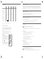
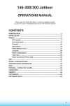
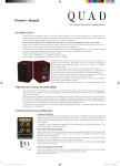
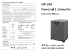
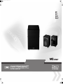
Ms subwoofer_A3.pdf
2008-10-14
15:13:45
Before installing this product read all these instructions.
Cautions:
IMPORTANT SAFETY INSTRUCTIONS
parts inside and you will render the warranty void.
This symbol indicates that there are important operating and
maintenance instructions in the literature accompanying this unit.
Site hi-fi electronics away from the loudspeakers on a rigid stand or cabinet.
This symbol indicates that dangerous voltage constituting a risk of
electric shock is present within this unit.
Site unscreened speakers and subwoofers at least 0.5m away from TV sets,
computers etc. Some manufacturers forbid the placing of objects on top of their
TV sets. Check your TV handbook before installing the centre speaker directly
on your TV set. Consult your TV dealer if you are in any doubt.
WARNING: TO REDUCE THE RISK OF FIRE OR ELECTRIC SHOCK, DO NOT EXPOSE
THIS APPARATUS TO RAIN OR MOISTURE.
Read these instructions.
Loudspeakers should not be placed directly facing other hi-fi units, or share the
same shelf or cabinet.
Use only attachments / accessories specified by the manufacturer.
DO NOT subject loudspeakers to excessive cold, heat, humidity or sunlight.
DO NOT block any ventilation openings.
Keep these instructions.
Heed all warnings.
Follow all instructions.
DO NOT use this apparatus near water.
Clean only with dry cloth.
DO NOT install near any heat sources such as radiators, heat registers, stoves,
or other apparatus (including amplifiers) that produce heat.
Protect the power cord from being walked on or pinched particularly at plugs,
convenience receptacles, and the point where they exit from the apparatus.
Unplug this apparatus during lightning storms or when unused for long
periods of time.
Refer all servicing to qualified service personnel. Servicing is required when the
apparatus has been damaged in any way, such as power-supply cord or plug
is damaged, liquid has been spilled or objects have fallen into the apparatus,
the apparatus has been exposed to rain or moisture, does not operate
normally, or has been dropped.
Install in accordance with the manufacturer’s instructions.
WARNING: If using spikes make sure that they do not pierce mains cable etc.
under /above the carpet.
DO NOT defeat the safety purpose of the polarized or grounding-type plug. A
polarized plug has two blades with one wider than the other. A grounding type
plug has two blades and a third grounding prong. The wide blade or the third
prong are provided for your safety. If the provided plug does not fit into your
outlet, consult an electrician for replacement of the obsolete outlet.
The apparatus must not be exposed to dripping or splashing and no objects
filled with liquids, such as vases, should be placed on the apparatus.
Use only with a cart, stand, tripod, bracket or table specified by the
manufacturer, or sold with the apparatus. When a cart is used, use
caution when moving the cart / apparatus combination to avoid
injury from tip-over.
CAUTION Mv-as SUBWOOFER: The mains power switch for this appliance is
located on the rear panel. To permit free access to this switch the apparatus
must be located in an open area without any obstructions. The mains power
plug must remain freely operable at all times.
CAUTION: Changes or modifications not expressly approved by the
manufacturer could void the user’s authority to operate this device.
IMPORTANT NOTICE TO UK USERS. The subwoofer is supplied with a plug
incorporating a fuse, the value of which is indicated on the pin face of the plug.
If the fuse or plug needs to be replaced refer to the instructions on Page 11.
When making any connections, switch the amplifier off.
When you switch on your system or change sources, set the volume control at
minimum and turn the level up gradually.
DO NOT use your amplifier at full volume.
Avoid extreme settings of tone controls or graphic equalisers. Ideally, they
should be set ‘flat’ or, if possible, bypassed.
DO NOT place heavy objects on top of loudspeaker cabinets.
Ensure that all loudspeakers in the system are correctly wired and are in
phase.
DO NOT connect your loudspeakers to the mains supply, except for
subwoofers.
CAUTION!
RISK OF ELECTRIC SHOCK
DO NOT OPEN
TO REDUCE THE RISK OF ELECTRIC SHOCK
DO NOT REMOVE COVER (OR BACK)
NO USER-REMOVEABLE PARTS INSIDE
REFER SERVICING TO QUALIFIED PERSONNEL
ADVERTISSEMENT: RISQUE DE CHOC ELECTRIQUENE PAS OUVRIR
DO NOT attempt to dismantle the loudspeaker. There are no user serviceable
Warning
When an amplifier is driven beyond its power output capabilities it will produce distorted results which will quickly
damage your speakers by overheating. Make sure that your amplifier is not left unattended when playing, for
example at parties, and turn the volume control down at the first sign of audible distortion.
Warranty Conditions
The warranty card enclosed should be completed and returned to
Mission or its Distributor within 8 days of purchase.
No Dealer or Distributor may vary the terms of this warranty which is
personal to the original purchaser and is not transferable.
Please retain the sales receipt as proof of purchase.
Warranty claims must wherever possible be made through the Dealer
from whom the equipment was purchased.
This warranty excludes:
Damage caused through neglect, accident, misuse, wear and tear, or
through incorrect installation, adjustment or repair by unauthorised
2
personnel. Any unauthorised servicing will result in loss of warranty.
Liability for damage or loss occurring in transit to or from the
purchaser.
Consequent damage, loss or injury, arising from or in conjunction with
this equipment.
Equipment for attention under warranty should be considered return
carriage paid. If equipment is found to comply with the published
specification, Mission reserves the right to raise a charge.
The above conditions do not affect your statutory rights as a
consumer.
Specifications
Welcome to Mission
MS-8
MS-10
MS-CUBE
MS-DUO
Recommended Amplifier:
Integrated 100W
amplifier
Integrated 150W
amplifier
Integrated 200W
amplifier
Integrated 150W
amplifier
Enclosure:
reflex
reflex
reflex
reflex
Effective Volume:
20 litres
35 litres
30 litres
30 litres
38 Hz - 120 Hz
30 Hz - 165 Hz
35 Hz - 110 Hz
35 Hz - 110 Hz
Filter Selection
35Hz-85Hz
(10 Hz steps)
40Hz - 200Hz
(variable)
35Hz-85Hz
(10 Hz steps)
35Hz-85Hz
(10 Hz steps)
Bass Unit
250mm
250mm
250mm
250mm
Net Weight
11.0 kg
18.6 kg
15.0 kg
15.2 kg
Dimensions (H x W x D): mm
300 x 300 x 330
410 x 280 x 500
380 x 345 x 370
380 x 330 x 355
Height on Feet mm
330
410
380
380
Electrical Class
Class II
Do not Earth.
Class I1
Requires Earth
Class I
Requires Earth
Class I
Requires Earth
Frequency Response
:
The Mv series is the latest in a long line of distinguished Mission loudspeakers. These technologically advanced loudspeakers will
complement the finest electronics and décor. Robust bass drivers and precision silk tweeters are used throughout the range.
Screw fastening tri-lobe multi-way binding posts feature on all models. Your Mission Mv loudspeakers will bring you great listening
pleasure for many years.
General Information
Please read these instructions carefully before installing your loudspeakers. A few minutes studying this manual will ensure
superb performance from your loudspeaker for many years.
Please pay attention to all cautions printed on the pages marked with this symbol.
Unpacking Your Loudspeakers
Mission reserves the right to change all specifications without notice. E & OE
•
Carefully unpack each loudspeaker.
•
Retain all the packing materials so that your loudspeaker can be repacked and shipped without damage.
•
If you dispose of the packing,do so with regard to all recycling provisions in your area..
Fitting Spikes
Note for UK Customers
Warning: Be careful. Loudspeaker spikes are very sharp.
When positioning the speakers avoid piercing any electrical cables.
The power cord on your subwoofer may be supplied with a plug incorporating a
fuse, the value of which is indicated on the pin face of the plug. Should the fuse
need to be replaced, an ASTA or BSI approved BS1362 fuse must be used of the
same rating. If the plug is cut off it must NOT be re-used. Dispose of any such
plug safely. There is a danger of electric shock if a cut-off plug is inserted into a
mains socket.
The wires in the mains lead are coloured in accordance with the following code:
Green and Yellow - Earth: Blue - Neutral: Brown - Live.
As the colours of the wires in the mains lead may not correspond with the
markings identifying the terminals in the replacement mains plug, proceed as
follows:
EARTH (GREEN/YELLOW)
MS-DUO; MS-10: MS-CUBE:
The wire coloured Blue must be connected to the
FUSE
terminal marked with the letter ‘N’ or coloured Black.
The wire coloured Brown must be connected to the
terminal marked with the letter ‘L’ or coloured Red.
The wire coloured Green and Yellow must be
LIVE
connected to the terminal marked with the letter ‘E’,or NEUTRAL
(BLUE)
(BROWN)
coloured Green, or Green and Yellow, or marked with
the Earth symbol
MS-8:
The wire coloured Blue must be connected to the
terminal marked with the letter ‘N’ or coloured Black.
The wire coloured Brown must be connected to the
terminal marked with the letter ‘L’ or coloured Red
•
Fitting the Spikes
•
Invert the loudspeaker and place the top on a soft stable surface, or place the
loudspeakers on a towel or soft cloth to protect the surface.
•
Screw a nut fully on to each spike but ensure the nut is not tight.
•
Place a washer over the spike retainer.
•
Screw a spike half way into each spike retainer fitted in the base of the cabinet.
•
Tighten the nut finger tight onto the spike retainer.
•
Carefully return the loudspeaker to its normal position.
•
Ensure that spikes do not pierce cables etc. under the carpet.
Adjusting the Spikes
FUSE
NEUTRAL
(BLUE)
The Mv-6 and Mv-8 loudspeakers are supplied with the spike retainers fitted to the plinth but you will need to fit the spikes
LIVE
(BROWN)
•
Loosen each collar slightly.
•
Adjust the height by screwing in or out one or more of the spikes
until the loudspeaker is stable and level.
•
Tighten the nut fully tight onto the spike retainer.
Warning: The Mv-6 and Mv-8 loudspeakers are heavy.
Always get someone to help you to lift and manoeuvre the loudspeakers.
Never drag a loudspeaker. When moving loudspeakers lift them clear of the floor and replace them carefully
14
11
3
The Mission MS-DUO Powered Subwoofer
b
c
d
e
Troubleshooting
Before investigating a problem, always switch off the system at the mains.
LINE LEVEL
OUTPUT
INPUT
CROSSOVER
FREQUENCY
VOLUME
55Hz
45Hz
LEFT
35Hz
If your system is not working properly please work through this checklist before returning a unit to your dealer.
65Hz
PHASE
75Hz
0°
180°
85Hz
RIGHT
ON
0
OFF
AUTO
POWER
10
Symptom
SPEAKER LEVEL INPUTS
f
MS-DUO
Active Subwoofer
L
R
N21090
g
h
i
j
1)
Possible Cause
No Sound
System not switched on; Speaker cables shorting terminals out; Wrong source selected
Sound lacks bass content
Bass reproduction indistinct
Subwoofer not switched on;
Subwoofer phase incorrect; Subwoofer crossover control too low
Excessive bass distortion at low volumes
Subwoofer level set too high; LFE level set too high; Subwoofer incorrectly wired
Excessive or distorted bass at high levels
System level set too high; Bass control set too high; Subwoofer too close to room corners
Distorted / rattling sounds at high levels
System level too high; Objects on subwoofer; Objects too close to subwoofer
Popping or thumping from the subwoofer
System level set high; Subwoofer level set too high; LFE level set too high
Television picture colour is distorted
Subwoofer too close to TV. (Switch off system and TV. Move units away. Leave 15 mins. Switch on.
Loudspeaker Maintenance
WARNING:
Subwoofers should only ever be cleaned with a soft dry cloth to remove fingermarks etc..
TO REDUCE THE RISK OF FIRE OR ELECTRICAL SHOCK,
DO NOT EXPOSE THIS PRODUCT TO RAIN OR MOISTURE
Serial Number
Power Inlet
Power
Never touch subwoofer drive units as they can be damaged by improper handling.
Never use a vacuum cleaner to clean a subwoofer grille. Brush it carefully by hand with a soft brush.
1!
FUSE T3.15AL250V
OFF
ON
AC220-240V 50Hz 150W
CAUTION:
ATTENTION:
DISCONNECT SUPPLY CORD
BEFORE CHANGING FUSE.
REPLACE ONLY WITH SAME
TYPE FUSE AND RATING
REPLACER LE FUSIBLE.
UTILISER UN FUSIBLE DE
RECHANGE DE MEME TYPE
ET CALIBRE
g Crossover Frequency Control
h Auto Power Switch
i Mains Power Indicator
j Mains ON/OFF Switch
1) IEC Mains Input Socket
1! Mains Power Fuse
NUMERICAL KEY
b Phase Control
c Line Level Outputs
d Line Level Inputs
e Volume Control
f Speaker Level Inputs
When cleaning the floor under a subwoofer; switch it off, unplug it from the mains supply then lift it clear of the floor and move it to
another location. Replace the subwoofer after cleaning.
Product Service
Should a fault occur with your subwoofer, please pack it correctly, using the original packing, so you can ship it safely..
Product for service should be returned to the appointed dealer from whom you purchased the product. If you experience difficulties or
there is no Mission dealer in your area, contact the Mission distributor for your country or the Main Service Centre for your region.
Authorised Service Centres
UK
Preliminaries
Power Connections
Open the carton and remove all the top packing pieces. Lift
the subwoofer out carefully. DO NOT lift the subwoofer out of
the carton using the protective bag. The unit is heavy; if you
cannot
manage it easily, get assistance.
The subwoofer is factory set to operate from the mains voltage
marked on the amplifier panel. Before connecting check this
voltage is correct for your mains supply.
!
230 volt products - 220 V to 240 V
Retain the packing materials. If you decide not to keep the
packing, please dispose of it having regard to any recycling
regulations in your area. Please retain the user manual. If you
transfer this equipment to a third party, please ensure all the
instructions are passed on with the product.
!
115 volt products - 110 Vs to 120 V
2
International Audio Group
IUnit 4, St Margaret’s Way,
Stukeley Meadows Industrial Estate
Huntingdon, Cambs, PE29 6EB
Tel:+44 (0)1480 447700 Fax: +44 (0)1480 431767
ASIA
IAG. Room 2310 - 2311, Press Building, Shennan Road C,
Shenzhen, China.
Tel: +86-755-82091200 Fax: +86-755-82091205
If you move to an area with a different mains supply, consult
your dealer for advice.
10
13
Stereo Reproduction
Changing the MS-DUO Operating Mode from Front-Firing to Down-Firing
Low Pass Filter:
The MS-DUO subwoofer is supplied in front-firing mode.
The subwoofer crossover point should be set having regard to the size and low frequency extension of the main speakers. The role of
the subwoofer is to extend the bass response of the system, not to increase the overall bass level. If the loudspeakers are large the
crossover should be set low, a value around 55 Hz is a good place to start. With smaller speakers this can be increased, up to 85Hz for
the small bookshelf units. As always the final value is determined by listening.
You can operate the subwoofer with the drive unit firing downwards (amplifier at the rear) or firing forwards (amplifier beneath the
subwoofer).
Low-level Listening
Remove the grille from the front of the loudspeaker
To change the mode from down firing to front firing:
Our ears are far more sensitive to midrange frequencies (2-5 kHz) than bass frequencies. Very low bass and especially percussive
bass is ‘felt’ rather than heard. At low sound levels bass frequencies appear to attenuate faster than midrange and treble. As the level
increases this bass roll-off decreases. Occasionally we may wish to listen to a normally loud piece of music at a low level but with
retention of the bass information.
b
Place a towel or similar on the ground.
Invert the subwoofer and place it carefully on the towel.
Remove the four cone feet from the subwoofer
c
Testing the system
The simplest way to test the system is to play, at a moderate level, music with deep consistent bass. Switching the subwoofer on and off
should cause change of the depth of bass, and the ambience will also alter. If there is a significant change in bass volume, or a
noticeable step in the bass response, or an increase in coloration when the subwoofer is playing, the setup needs to be refined. By
selecting different crossover and volume settings, you will be able readily to identify the most favourable combination.
Dolby Labs Recommended 7.1 Placement
Left Front
e
Mod
ring
i
F
t
Fron
Centre
LFE
22º
Right Front
Screw the cone feet tightly into the holes that held the pegs
Stand the subwoofer on its feet as shown in the illustration
Unscrew the four pegs that held the grille in place
30º
e
d
90º
Left Surround
Right Surround
110º
135º
Down F
iring M
ode
150º
Left Back
Right Back
In down firing mode the grille must be removed
Store the grille and the pegs safely for future re-use.
Reverse the procedure to change the mode.
(Single Back channel for 6.1
Which mode should I use?
You should experiment with different operating modes to see which one you prefer. Here are some notes which may help you.
!
!
Front firing mode keeps the drive unit away from walls and offers a better focussed sound with lowest bess distortion.
If your floor is a hard wood or stone floor, front-firing will offer advantages especially if you are using a suspended wood floor.
In front firing mode the amplifier faces downwards so there are some potential disadvantages:
!
!
12
9
If you have a deep shag pile carpet, there may be insufficient ventilation for the amplifier and we do not advise you to use this
mode of operation.
Although the Subwoofer controls are designed to be “set and forget”, if you are likely to adjust the controls often, down firing
mode is easier for day to day use.
5
The Mission MS-10 Powered Subwoofer
Setting Up your Subwoofer - All Models
!
!
!
!
!
!
b
c
d
e
f
g
i
h
j
NUMERICAL KEY
b Crossover Frequency Control
c Mains/Standby Indicator
d Volume Control
e Phase Switch
f LEFT Line Input
g RIGHT/LFE Input
h Speaker Level Inputs
i Mains Voltage Selector*
j Mains ON/OFF Switch
1) IEC Mains Input Socket
1! Mains Power Fuse
1)
1!
Set the subwoofer power switch to OFF.
Turn the system Volume Control to minimum.
Re-check all system connections.
Connect the supplied power lead to the IEC power socket on the subwoofer and connect the mains plug into the wall socket.
Set the subwoofer volume control midway (12 o'clock)
Switch on the mains power.
Fine Tuning Your Subwoofer
Switch on the subwoofer power switch. Check that the power indicator on the amplifier panel glows. Now switch on the system.
Play a programme with extended bass and set the system volume to a reasonable level. Adjust the subwoofer volume control to
produce the desired level of bass.
PHASE SWITCH: If the bass is indistinct or lacks depth, the Phase switch may need adjustment. Set the switch to 0º and listen
carefully to some music with extended bass. If there is insufficient bass output from the sub-woofer set the Phase switch to 180º.
Select the position which produces the most natural, extended bass.
LOW PASS (CROSSOVER) FILTER: This adjusts the blend between the subwoofer and the main speakers. and enables the
system to be set up for optimum bass performance. The higher settings are for use with bookshelf loudspeakers, the lower
settings for large floorstanding models. If you choose too low a setting with small speakers, there will be a ‘hole’ in the bass
response; too high a setting with large speakers will result in the upper bass becoming bloated.
AUTOPOWER SWITCH- MS-CUBE; MS-8; MS-DUO
In normal mode the subwoofer is permanently on. This may result in low level hum or noise if the rest of the system is switched off
and the subwoofer is left switched on. Setting the AUTO switch to ON automatically turns the subwoofer on when a signal is
detected at any of the inputs and turns it off (Standby Mode) after a period of inactivity. We recommend the AUTO switch be set to
ON for normal operation.
In AUTO mode the indicator on the front of the subwoofer will glow RED when the unit is in Standby and GREEN when operational.
If your subwoofer is disconnected from the mains or the Power switch is “Off”, the indicator will be extinguished.
AUTO SWITCH- MS-10. AUTOPOWER operation is built into the subwoofer and cannot be turned on and off.
Preliminaries
When moving speakers, do not let the spikes pierce objects
which may be concealed under a carpet.
When the system is not in use for extended periods, we suggest you switch off the subwoofer to protect it from switching noises.
Open the carton and remove all the top packing pieces. Lift
the subwoofer out carefully. DO NOT lift the subwoofer out of
the carton using the protective bag. The unit is heavy; if you
cannot manage it easily, get assistance.
Never drag loudspeakers. If you cannot lift them easily, get
someone to assist.
LOUDSPEAKER SIZES: Many digital AV processors require you to specify the size of speakers in the various channels. These are
usually ‘Large’ or ‘Small’. We recommend that you set the centre and surround speakers to 'Small'. This will direct all the bass in the
system to the subwoofer and provide clean, deep and louder bass. Set the ‘Subwoofer’ option on the processor to 'On’ or 'Yes'.
Power Connections
Retain the packing materials. If you decide not to keep the
packing, please dispose of it having regard to any recycling
regulations in your area. Please retain the user manual. If you
transfer this equipment to a third party, please ensure all the
instructions are passed on with the product.
The subwoofer is factory set to operate from the mains voltage
marked on the amplifier panel. Before connecting check this
voltage is correct for your mains supply.
!
230 volt products - 220 V to 240 V
Attaching Spikes
!
115 volt products - 110 Vs to 120 V
Carefully invert the subwoofer. Protect the top
surface from scratches or damage when the
subwoofer is inverted.
The subwoofer has four spikes. Prepare the
spikes as shown and screw one spike into the
threads on the base of teach subwoofer foot.
Set the subwoofer upright taking care not to
cause damage.
Adjust the spikes in and out until the subwoofer
is firm and level. Use a spirit level to assist you.
Now tighten the nuts securely.
6
Subwoofer Settings for Front Loudspeakers
CROSSOVER
FREQUENCY
55Hz
Set large floorstanding loudspeakers to ‘large’. Smaller floorstanding
loudspeakers may be optionally set to ‘small’. In this case the subwoofer
crossover setting should be 55Hz. If you find the bass excessive, set the
loudspeaker to ‘large’.
45Hz
85Hz
MS-CUBE; MS-8; MS-DUO
CROSSOVER
FREQUENCY
55Hz
*DO NOT change the operating voltage of this product
without seeking expert advice first.
75Hz
35Hz
MS-10
If you move to an area with a different mains supply, consult
your dealer for advice.
65Hz
Set bookshelf and stand mounted loudspeakers to ‘small’. If you are using a
digital AV processor the subwoofer crossover setting should be 85Hz.
45Hz
35Hz
65Hz
75Hz
85Hz
Setting Levels (Read this together with your processor instructions),
Once the loudspeaker settings have been finalised, put the AV amplifier into its “Test” mode. Adjust the levels until all channels are
equally loud. You may need to adjust the subwoofer output level. Avoid setting too high a level which may limit the subwoofer’s
ability to respond to large bass transients. Set a sensible level going into the subwoofer. The subwoofer volume control should be
between 12 o’clock and 3 o’clock .
LFE: If all the speakers are set to ‘Small’, the LFE channel will be combined with the bass from other channels and all this feeds into
the subwoofer. When you set the LFE level from your AV processor, use care as the LFE channel may contain powerful low
frequencies which may overload a domestic subwoofer. If, during a programme, you hear popping or thumping noises coming
from the subwoofer, immediately turn the AV Processor's volume level down and then back off the LFE level. If this does not cure
the problem, back off the volume level at the subwoofer.
11
The Mission MS-8 and MS-CUBE Powered Subwoofers
Connecting the MS-10 Subwoofer
AV AMPLIFIER
A/V Processor Connections
Your subwoofer has been designed for optimum performance
with a Digital processor. If your AV processor has a line level or
LFE subwoofer output you should use this connection. You will
need to purchase a single screened RCA phono lead from your
dealer. Connect this lead to the LFE/R input of the Subwoofer as
shown.
RIGHT
LEFT
REAR
RIGHT
CENTRE
b
c
d
e
b
c
d
e
LEFT
FRONT
Subwoofer Out (Line Level)
LINE LEVEL
INPUT
OUTPUT
CROSSOVER
FREQUENCY
VOLUME
55Hz
65Hz
PHASE
75Hz
45Hz
LEFT
0°
35Hz
180°
85Hz
RIGHT
ON
0
OFF
AUTO
POWER
10
SPEAKER LEVEL INPUTS
f
f
MS-CUBE
Active Subwoofer
L
R
N21090
Alternatively, you may use a split mono lead from the processor
to both inputs of the subwoofer. In this case the input level at the
subwoofer will be slightly higher.
RIGHT
LEFT
REAR
RIGHT
CENTRE
LEFT
g
g
h
h
i
j
1)
i
j
1)
FRONT
AV AMPLIFIER
Stereo Line Output Connections
L
If your amplifier has a spare preamplifier output or a stereo subwoofer output, connect the sub-woofer as shown. You will need
a stereo screened RCA phono cable.
Pre Out - Main In Connections
If you use a stereo pre and power amplifier, or a stereo amplifier
where the pre and main amplifier can be separated, connect
the sub-woofer as shown. You will need two screened RCA ‘Y’
adaptors and two single RCA phono cables.
Remove the Pre-Main links on your amplifier. Connect the RCA
‘Y’ adaptors and cables as shown. Connect one leg of the ‘Y’
adaptor to the Left Channel Pre Out socket on the amplifier and
the other leg to the Left Channel Main In socket. Connect the
remaining plug on this combination to the Left Channel Line
Level Input on the sub-woofer. Repeat this for the Right Channel.
R
RIGHT
LEFT
REAR
RIGHT
CENTRE
LEFT
FRONT
Stereo Outputs (Line Level)
(x2)
Power Inlet
PRE
OUT
Power
MAIN
IN
1!
OFF
ON
AC220-240V 50Hz 150W
AMPLIFIER
R
RIGHT
ATTENTION:
DISCONNECT SUPPLY CORD
BEFORE CHANGING FUSE.
REPLACE ONLY WITH SAME
TYPE FUSE AND RATING
REPLACER LE FUSIBLE.
UTILISER UN FUSIBLE DE
RECHANGE DE MEME TYPE
ET CALIBRE
g Crossover Frequency Control
h Auto Power Switch
i Mains Power Indicator
j Mains ON/OFF Switch
1) IEC Mains Input Socket
1! Mains Power Fuse
NUMERICAL KEY
b Phase Control
c Line Level Outputs
d Line Level Inputs
e Volume Control
f Speaker Level Inputs
AMPLIFIER
LEFT
RIGHT
Preliminaries
Attaching Spikes (MS-CUBE)
Open the carton and remove all the top packing pieces. Lift
the subwoofer out carefully. DO NOT lift the subwoofer out of
the carton using the protective bag. The unit is heavy; if you
cannot
manage it easily, get assistance.
Spikes may be fitted if required. To fit the spikes, follow the
instructions for the MS-10 on the previous page.
Retain the packing materials. If you decide not to keep the
packing, please dispose of it having regard to any recycling
regulations in your area. Please retain the user manual. If you
transfer this equipment to a third party, please ensure all the
instructions are passed on with the product.
The subwoofer is factory set to operate from the mains voltage
marked on the amplifier panel. Before connecting check this
voltage is correct for your mains supply.
SUBWOOFER
SPEAKER LEVEL INPUTS
R
CAUTION:
LEFT
TO FRONT
SPEAKERS
The high level Speaker connections should be used only if your
amplifier does not have a line level subwoofer output. In this
connection the subwoofer is fed together with the Front
loudspeakers. For this you will need two extra twin core cables.
Connect the Left Speaker Terminals on the subwoofer to the
Front Left speaker terminals on the amplifier. Connect the Red (+)
speaker terminal on the amplifier to the Red (+) terminal on the
subwoofer. Connect the Black (-) speaker terminal on the
amplifier to the Black (-) terminal on the subwoofer. Now
connect the Right Speaker terminals on the subwoofer to the
Front Right speaker terminals of the amplifier.
1!
FUSE T3.15AL250V
L
Speaker Level Connections
Measure out two loudspeaker cables
of the appropriate length.
Prepare the cables as shown.
WARNING:
TO REDUCE THE RISK OF FIRE OR ELECTRICAL SHOCK,
DO NOT EXPOSE THIS PRODUCT TO RAIN OR MOISTURE
Serial Number
L
Power Connections
!
230 volt products - 220 V to 240 V
!
115 volt products - 110 Vs to 120 V
If you move to an area with a different mains supply, consult
your dealer for advice.
10
7
6
7
Connecting the MS-8 , MS-CUBE and MS-DUO
Positioning your Subwoofer
Although the unit may be placed almost anywhere in the room, even behind
the sofa or the TV set, we recommend that it be placed in front of the listener
and as central to the listening position as possible. The subwoofer should not
be operated within 450mm of a television set as the drive unit magnet may
distort the picture.
>200mm
200mm
>
We suggest you position the subwoofer about 20cm (8 inches) from the wall.
A position close to the wall will enhance the bass; placing it across a room
corner will increase the bass further, possibly at the expense of clarity.
Experiment with a variety of locations and sources before making a final
decision.
The drive unit and bass ports move a lot of air at high volume, so make sure
you do not place your subwoofer near surfaces or objects that may rattle.
There should be a mains outlet within easy reach.
Your system will perform best if there is a clear line of sight between the
subwoofer and the listening position.
NOTE: When running signal cables to the subwoofer, keep them clear of obstructions. Do not run a long signal cable close to mains
cables or cables carrying heavy digital traffic.
The MS-8 , MS-CUBE and MS-DUO feature identical connectivity and are connected to the rest of your system in exactly
the same way.
AV AMPLIFIER
A/V Processor Connections
INPUT
OUTPUT
INPUT
OUTPUT
LEFT
Your subwoofer has been designed for optimum performance
with a Digital processor. If your AV processor has a line level or
LFE subwoofer output you should use this connection. You will
need to purchase a single screened RCA phono lead from your
dealer. Connect this lead to the Left line input of the Subwoofer
as shown opposite.
RIGHT
RIGHT
LEFT
REAR
RIGHT
CENTRE
LEFT
FRONT
Subwoofer Out (Line Level)
LEFT
Alternatively, you may use a split mono lead from the processor
to both inputs of the subwoofer. In this case the input level at the
subwoofer will be slightly higher.
RIGHT
LEFT
REAR
RIGHT
CENTRE
RIGHT
LEFT
FRONT
AV AMPLIFIER
Stereo Line Output Connections
L
If your amplifier has a spare preamplifier output or a stereo subwoofer output, connect the sub-woofer as shown. You will need
a stereo screened RCA phono cable.
Pre Out - Main In Connections
If you use a stereo pre and power amplifier, or a stereo amplifier
where the pre and main amplifier can be separated, connect
the sub-woofer as shown. You will need two screened RCA ‘Y’
adaptors and two single RCA phono cables.
Remove the Pre-Main links on your amplifier. Connect the RCA
‘Y’ adaptors and cables as shown. Connect one leg of the ‘Y’
adaptor to the Left Channel Pre Out socket on the amplifier and
the other leg to the Left Channel Main In socket. Connect the
remaining plug on this combination to the Left Channel Line
Level Input on the sub-woofer. Repeat this for the Right Channel.
R
RIGHT
LEFT
REAR
RIGHT
CENTRE
LEFT
FRONT
Stereo Outputs (Line Level)
(x2)
PRE
OUT
MAIN
IN
L
AMPLIFIER
R
RIGHT
LEFT
Speaker Level Connections
TO FRONT
SPEAKERS
The high level Speaker connections should be used only if your
amplifier does not have a line level subwoofer output. In this
connection the subwoofer is fed together with the Front
loudspeakers. For this you will need two extra twin core cables.
Measure out two loudspeaker cables
of the appropriate length.
Prepare the cables as shown.
AMPLIFIER
LEFT
RIGHT
SUBWOOFER
SPEAKER LEVEL INPUTS
Connect the Left Speaker Terminals on the subwoofer to the
Front Left speaker terminals on the amplifier. Connect the Red (+)
speaker terminal on the amplifier to the Red (+) terminal on the
subwoofer. Connect the Black (-) speaker terminal on the
amplifier to the Black (-) terminal on the subwoofer. Now
connect the Right Speaker terminals on the subwoofer to the
Front Right speaker terminals of the amplifier.
8
R
L
9