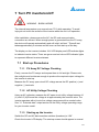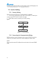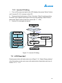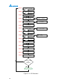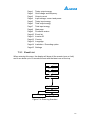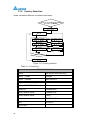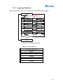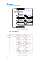
1
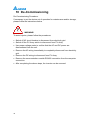
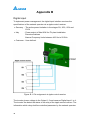
Table of Contents
1
General Information ............................................................ 1
1.1 Scope of delivery ................................................................................ 1
1.2
1.3
1.4
1.5
1.6
2
Installation and Wiring ........................................................ 4
2.1
2.2
2.3
2.4
3
General Warnings / Notes on Safety .................................................. 1
Validity ................................................................................................ 2
Product Description ............................................................................ 2
How it Works ...................................................................................... 3
Additional Information ........................................................................ 3
Instruction before Installation ............................................................. 4
Unpacking .......................................................................................... 4
Package Inspection ............................................................................ 5
Identification Label ............................................................................. 6
Product Overview................................................................ 7
3.1 Dimensions ........................................................................................ 7
3.2 Function Introduction .......................................................................... 7
3.2.1 LCD Display and Buttons ............................................................. 8
3.2.2 Inverter Input/Output Interface ..................................................... 8
4
Installation ........................................................................... 9
4.1 Installation Location ........................................................................... 9
4.2 Mounting ............................................................................................ 9
5
Wiring ................................................................................. 12
5.1 Preparation before Wiring ................................................................ 12
5.2 AC Grid Connection: L + N + PE ................................................... 13
5.2.1 Required protective devices and cable cross-sections .............. 14
5.3 DC Connection (from PV Array) ....................................................... 15
5.4 Communication Module ...................................................................... 16
5.4.1 RS-485 Connection ..................................................................... 16
6
Active/Reactive Power Control and LVRT (Optional) ..... 18
6.1 Active Power Control ........................................................................ 18
6.1.1 Power Limit ................................................................................ 18
6.1.2 Power vs. Frequency ................................................................. 18
6.2 Reactive Power Control ................................................................... 19
6.2.1 Fixed Power Factor cosφ (VDE-AR-N 4105,CEI 0-21) .............. 20
6.2.2 cosφ(P) (VDE-AR-N 4105,CEI 0-21) ......................................... 20
6.2.3 Fixed Reactive Power InVAR(CEI 0-21) .................................... 20
6.2.4 Reactive Power/ Voltage Characteristic Q(U)(CEI 0-21) ............ 20
i
6.3 Low Voltage Ride Through (LVRT) ................................................... 22
7
Turn PV inverteron/off....................................................... 23
7.1 Start-up Procedures ......................................................................... 23
7.1.1 PV Array DC Voltage Checking .................................................. 23
7.1.2 AC Utility Voltage Checking ....................................................... 23
7.1.3 Starting up the Inverter............................................................... 23
7.2 Inverter Setting ................................................................................. 24
7.2.1 Country Setting .......................................................................... 24
7.2.2 Connecting the Communication Wiring ...................................... 24
7.2.3 Inverter ID Setting ...................................................................... 25
7.3 LCD flowchart................................................................................... 25
7.3.1 Event List ................................................................................... 27
7.3.2 Country Selection....................................................................... 28
7.3.3 Language Selection ................................................................... 29
7.3.4 Insulation Mode ......................................................................... 30
7.3.5 Time Setting ............................................................................... 30
7.3.6 Settings Page ............................................................................ 31
7.3.7 Italy Self-test&Comando locale .................................................. 31
8
9
Maintenance ...................................................................... 34
MeasurementError Message and Trouble Shooting ....... 35
9.1 Measurement ................................................................................... 35
9.2 Error Message & Trouble Shooting .................................................. 36
10 De-Commissioning ........................................................... 44
11 Technical Data ................................................................... 45
11.1 Specifications ................................................................................... 45
Appendix A ............................................................................... 47
A.1 Multi-function relay output connection ................................................ 47
Appendix B ............................................................................... 48
ii
Figure
Figure 1-1: Solar system operation illustration ........................................ 3
Figure 2-1: Unpacking process............................................................ 4
Figure 2-2: The identification label ....................................................... 6
Figure 3-1: Dimensions of RPI H3A/ H4A/ H5A ...................................... 7
Figure 3-2: Inverter exterior objects ...................................................... 7
Figure 3-3: LCD display and buttons .................................................... 8
Figure 3-4: Input/output interface ......................................................... 8
Figure 4-1: Attaching the mounting bracket for RPI H3A / H4A / H5A ........ 10
Figure 4-2: Correct and incorrect installation illustration ......................... 10
Figure 4-3: Adequate installation gap ................................................. 11
Figure 5-1: Connection of a system for floating solar array ..................... 12
Figure 5-2: Connection of a system for solar array grounding .................. 13
Figure 5-3: AC plug illustration (C01620E0028001, AMPHENOL CORP) ... 14
Figure 5-4: DC Wiring illustration ....................................................... 16
Figure 5-5: Communication module ................................................... 16
Figure 5-6: Multi-inverter connection illustration .................................... 17
Figure 6-1: Power vs. frequency characteristic ..................................... 19
Figure 6-2: cosφ(P) characteristic ...................................................... 20
Figure 6-3: Q(U) characteristic .......................................................... 21
Figure 6-4: LVRT characteristic ......................................................... 22
Figure 7-1: Country Setting .............................................................. 24
Figure 7-2: Inverter ID Setting ........................................................... 25
Figure 7-3: LCD flowchart ................................................................ 26
Figure 7-4: Event log flowchart .......................................................... 27
Figure 7-5: Country selection ............................................................ 28
Figure 7-6: Language selection ......................................................... 29
Figure 7-7: Insulation mode .............................................................. 30
Figure 7-8: Time settings ................................................................. 30
Figure 7-9: Settings page ................................................................. 31
Figure 7-10: Italy Comando locale ..................................................... 32
Figure 7-11: Italy self-test flowchart .................................................... 33
Figure A-1: Multi-function Relay location ............................................. 47
Figure B-1: Pin assignment at ripple control receiver ............................. 48
iii
Table
Table 2-1: Packing list ....................................................................... 5
Table 5-1: Recommended upstream protection .................................... 14
Table 5-2: AC wire requirement ......................................................... 14
Table 5-3: Order Numbers for MC4 connectors .................................... 15
Table 5-4: Minimum cable size .......................................................... 15
Table 5-5: Definition of RS485 .......................................................... 17
Table 5-6: RS-485 data format .......................................................... 17
Table 7-1: Country list ..................................................................... 28
Table 7-2: Language list................................................................... 29
Table 9-1: Measurement and message ............................................... 35
Table 9-2: Error message ................................................................. 36
Table 11-1: Specifications................................................................. 45
iv
1 General Information
1.1 Scope of delivery
Congratulations on the purchase of your Delta RPI H3A / H4A / H5A grid-tied
solar inverter. This manual assists you in becoming familiar with this product.
Please observe all safety regulations and take into account technical
connection conditions required at your local grid utility.
1.2 General Warnings / Notes on Safety
Careful handling of the product will contribute to service life durability and
reliability. Both are essential to ensure maximum yield from your product. As
some of the solar inverter models are heavy, two people may be required for
lifting purposes.
CAUTION!
During operation of electrical devices, certain parts are under dangerous
voltage.
Inappropriate handling can lead to physical injury and material damage.
Always adhere to the installation regulations. Installation may only be
conducted by certified electricians.
WARNING!
Repair work on the device should ONLY be carried out by the manufacturer.
No user serviceable parts inside.
Please observe all points in the operation and installation manual. Isolate the
device from the grid and the PV modules before undertaking work on the
device.
DANGER!
To avoid risk of electrical shock, do not open the solar inverter. The inverter
contains no user-serviceable parts. Opening the inverter will void the warranty.
Dangerous voltage is present for 5 minutes after disconnecting all sources of
power.
1
Remember that the unit has a high leakage current. The PE conductor MUST
be connected prior to commencing operation.
WARNING:BURN HAZARD!
The unit may reach very high temperatures and the device surface can
become quite hot. Sufficient cooling is necessary for optimal yield.
1.3 Validity
This user manual describes the installation process, maintenance, technical
data and safety instructions of the following solar inverter models under the
DELTA brand.
• RPI H3A
• RPI H4A
• RPI H5A
1.4 Product Description
This device is a single-phase grid-tie solar inverter. It converts direct current
(DC) electricity from the PV array into single-phase alternating current (AC) to
feed the excess generated power back to the local grid.
This inverter allows for a wide voltage input range (100~550VDC) and has a
high performance efficiency and user friendly design and operation. In addition,
the special DSP (Digital Signal Processor) design reduces the complexity of
the circuit and electronic components. Please note that this device does not
support off-grid function. The features for RPI H3A / H4A / H5A are shown
below.
Features
•
•
•
•
•
•
•
•
2
Power Rating: 3kVA (RPI H3A), 4kVA (RPI H4A), 5kVA (RPI H5A)
Single–phase (L + N + PE), Grid-tie, transformerless solar inverter
Maximum efficiency: >97.5%
Europe efficiency: 96.8% (RPI H3A) , 97.0%(RPI H4A), 96.8%(RPI H5A)
Reactive power capability (Cap 0.8 – Ind 0.8)
Total harmonic distortion (THD < 3%) @ full load
2 MPP Trackers
16×2 monochrome LCD display
1.5 How it Works
The operation of a solar inverter is shown in Figure 1-1. In order to save
energy and electricity, the solar inverter converts the DC input power supplied
from the PV Array into single-phase AC output power to Grid.
Figure 1-1: Solar system operation illustration
1.6 Additional Information
For more detailed information for RPI H3A/ H4A/ H5A or other related product
information, please visit : http://www.deltaww.com.
3
2 Installation and Wiring
2.1 Instruction before Installation
Due to the variety of users and installation environments, it is recommended to
read this manual thoroughly before installation. Installation of the unit and
start-up procedures must be carried out by accredited technicians.
2.2 Unpacking
Unpacking process is shown as Figure 2-1.
Figure 2-1: Unpacking process
Upon receiving your brand new RPI inverter, you will be required to remove its
protective packaging. This packaging consists of various materials that will
need to be disposed of according to the specific recycling marking printed on
them. Please note that cardboard may be recycled, whereas polystyrene foam
may not. Please dispose of the packaging materials in a correct manner to
ensure a better environment for us all.
4
2.3 Package Inspection
Unforeseeable events causing damage or movement may occur during
shipment. Please check for damage on the packaging upon receiving your
inverter.
Please check the model number and the serial number on the packaging is
identical with the model number and serial number on the unit itself.
Check if all the accessories are in the package, the standard accessories are
list as Table 2-1:
Table 2-1: Packing list
RPI H3A / H4A /H5A
Object
Qty
Description
PV Inverter
1
Solar inverter
User Manual
1
The installation manual is designed to provide
information on safety, installation, technical
specifications and safe operation of the inverter.
AC Plug
1
AC Connector plug
Wall-Mount
Bracket
1
Wall-mount bracket to mount the solar inverter
securely on the wall
M4 Screw
2
To fix solar inverter on the bracket
Caution: If there is any visible damage to the inverter/accesories or any
damageto the packaging, please contact your inverter supplier.
5
2.4 Identification Label
Users can identify the model number by the information on the product label.
The model number, serial number and other specifications can be located on
the product label. For label location, please refer to Figure 2-2.
Figure 2-2: The identification label
6
3 Product Overview
3.1 Dimensions
Figure 3-1: Dimensions of RPI H3A/ H4A/ H5A
3.2 Function Introduction
The Inverter’s exterior is shown in Figure 3-2. The description for individual
objects can be found in sections 3.2.1 and 3.2.2.
Figure 3-2: Inverter exterior objects
7
3.2.1 LCD Display and Buttons
Figure 3-3: LCD display and buttons
3.2.2 Inverter Input/Output Interface
Figure 3-4: Input/output interface
Note: The DC switch is only presented in the -120 models. Model series -020
does not have the DC switch.
8
4 Installation
4.1 Installation Location
WARNING!
Do not install the unit near or on flammable surfaces.
Please mount the unit tightly on a solid/smooth surface
CAUTION!
The unit should not be installed in direct sunlight.
4.2 Mounting
This unit is designed to be wall-mounted. Please ensure the installation is
perpendicular to the floor and the AC plug located at the base of the unit. Do
not install the device on a slanting wall. The dimensions of the mounting
bracket are shown in the figure below. 8 ofφ5.5mm screws are required for
the mounting plate(hole size: φ6.5mm). Fix the supplied wall-mount plate
securely on the wall before attaching the inverter onto the mounting plate.
9
Figure 4-1: Attaching the mounting bracket for RPI H3A / H4A / H5A
Figure 4-2: Correct and incorrect installation illustration
10
CAUTION!
• The bracket supplied with the unit is specially designed and should be the
only mounting device used for the unit.
• It is recommended to install the inverter in a suitable location which offers
easy and safe access for service and maintenance.
• Please leave an appropriate gap in between units when installing multiple
solar inverter systems.
• Please install solar inverter at eye level to allow easy observation for
operation and parameter setting.
• Ambient temperature for operation: -25°C~+60°C (power derating above
40°C).
Please ensure the spacing requirement to allow for sufficient convective
cooling. It is essential to ensure sufficient space for product operation as
shown in Figure 4-3.
> 50CM
> 30CM
> 30CM
> 30CM
> 50CM
Figure 4-3: Adequate installation gap
11
5 Wiring
5.1 Preparation before Wiring
1. Ensure voltage values and polarities are correct.
2. When grounding the solar array, an isolation transformer is required due to
the RPI H3A / H4A /H5A not having galvanic isolation between the DC-input
and AC-output.
3. The ground fault detection is a fixed internal setting. It cannot be modified.
4. Whole system wiring can be seen in Figure 5-1 and Figure 5-2.
5. Please refer to Figure 5-1 for connections. Inverter can accept DC inputs in
parallel (2 MPP trackers/ 2 parallel input).
Figure 5-1: Connection of a system for floating solar array
12
Figure 5-2: Connection of a system for solar array grounding
WARNING! SHOCK HAZARD
Note: Whenever a PV array is exposed to sunlight, a shock hazard may exist
due to output wires or exposed terminals. To reduce the risk of shock during
installation, cover the array with an opaque (dark) material and ensure that the
Disconnect Device in the inverter is set to OFF before commencing any wiring.
5.2 AC Grid Connection:
L + N + PE
WARNING!
Before commencing AC wiring, please ensure AC breaker is switched off.
13
5.2.1 Required protective devices and cable
cross-sections
Table 5-1: Recommended upstream protection
RPI H3A
RPI H4A
RPI H5A
Power rating
Upstream circuit breaker
3.75kVA
5 kVA
6.25 kVA
20A
25A
30A
Please use appropriate wire to connect poles (According to the Table 5-2).
Table 5-2: AC wire requirement
Current Rating
Wire size
Torque
>20A (RPI H3A),
>25 A (RPI H4A),
>30 A (RPI H5A)
3-4mm2 / 12 AWG
0.8~1Nm
L
PE
N
1: L
2: N
: PE
Section drawing
Figure 5-3: AC plug illustration (C01620E0028001, AMPHENOL CORP)
14
5.3 DC Connection (from PV Array)
WARNING!
• When undertaking DC wiring, please ensure the correct polarities are
connected.
• When undertaking DC wiring please ensure that the DC isolator switch on
the PV array is OFF.
CAUTION!
The maximum open circuit voltage of the PV Array must not exceed 600Vdc.
The maximum recommended input power to the inverter is:
3150W (RPI H3A)/ 4200W (RPI H4A)/ 5250W (RPI H5A).
Note: The device installed between the PV Array and inverter must meet the
rating of voltage higher than this device’s maximum input voltage.
The RPI range of PV inverters uses genuine Multi-Contact® MC4 connectors.
Table 5-3: Order Numbers for MC4 connectors
CABLE
WIRE SIZE
COUPLER
2.5 MM
POLARITY
(AWG 14)
2
WIRE SIZE 4.0
2
MM - 6.0 MM
2
FEMALE
MALE
CABLE
CABLE
COUPLER
COUPLER
MULTI-CONTACT
ORDER NUMBER
Plus coupler
Minus
coupler
(AWG 12-10)
•
•
•
Minus
32.0011P0001-UR
32.0013P0001-UR
32.0014P0001-UR
•
•
coupler
32.0012P0001-UR
•
•
Plus coupler
32.0010P0001-UR
32.0016P0001-UR
•
32.0015P0001-UR
32.0017P0001-UR
Table 5-4: Minimum cable size
Current Rating
DC 10 A (RPI H3A)
DC 12 A(RPI H4A / H5A)
Wire size
2-3mm2 / 14 AWG
15
DC wiring polarities are divided into Plus and Minus, which are shown in
Figure 5-4. The connection shall conform to the indication marked on inverter.
Figure 5-4: DC Wiring illustration
5.4 Communication Module
The Communication Module enables communication between the unit and a
computer and provides 2 RS-485 ports. When using this module, the first step
is to take off the cover located at the bottom right of inverter and pull out the
RS485 socket as shown in Figure 5-5.
Figure 5-5: Communication module
5.4.1 RS-485 Connection
The pin definition of RS-485 shown in Table 5-5 and protocol settings are listed
in Table 5-6. Installer must switch the terminal resistor switch to ON when only
a single inverter is installed. The wiring of multi-inverter is shown in Figure 5-6.
The terminal resistor switch of the first and last inverters should be switched
ON, and the others OFF.
16
Table 5-5: Definition of RS485
PIN
FUNCTION
1
VCC
2
GND
3
DATA+
4
DATA-
5
DATA+
6
DATA-
Figure 5-6: Multi-inverter connection illustration
Table 5-6: RS-485 data format
RS-485 Data format
Baud rate
9600 / 19200
Data bit
8
Stop bit
1
Parity
N/A
17
6 Active/Reactive Power Control and LVRT
(Optional)
There are 2 settings for active power and 4 settings for reactive power control
that can be configured based on the requirement of the local network operator.
6.1 Active Power Control
6.1.1 Power Limit
Users can reduce inverter output power by set percentage of actual or rated
power.
6.1.2 Power vs. Frequency
According to VDE-AR-N 4105 (5.7.3.3):
At frequencies between 50.2Hz and 51.5Hz, all adjustable power generation
systems shall reduce (for frequency increase) or increase (for frequency
decrease) the active power Pm generated instantaneously (at the time of
exceeding the mains frequency 50.2Hz; freezing the value on the current level)
with a gradient of 40% of Pm per Hertz).
According to CEI 0-21 (8.5.3.2):
Within a frequency range from 50.3Hz to 51.5Hz, all adjustable production
plants equipped with static converters have to be able to reduce the currently
generated active power in case of an increase of the frequency with a variable
drop of 2% to 5% with a default value of 2.4% (with corresponds to a power
gradient of 83.3%/Hz).
User can set all necessary settings to meet the requirements from network
operator. Please refer to actual Power vs. Frequency shown in Figure 6-1 for
the settings procedure.
18
Power vs. frequency curve for VDE-AR-N 4105
Power vs. frequency curve for CEI-021
Figure 6-1: Power vs. frequency characteristic
6.2 Reactive Power Control
With active power output, it must be possible to operate the generating plant in
any operating point with at least a reactive power output corresponding to a
active factor at the network connection point of
• cos ϕ = 0.8 underexcited to 0.8 overexcited
• (VDE-AR-N 4105,CEI 0-21 cos ϕ = 0.9 underexcited to 0.9 overexcited)
Values deviating from the above must be agreed upon by contract. With active
power output, either a fixed target value for reactive power provision or a target
value variably adjustable by remote control (or other control technologies) will
be specified by the network operator in the transfer station.
The setting value is either:
19
• fixed power factor cosφ (VDE-AR-N 4105 ,CEI 0-21)
• displacement factor/active power characteristic curve cosφ(p) (VDE-AR-N
4105 ,CEI 0-21)
• fixed reactive power in Var.(CEI 0-21)
• reactive power/voltage characteristic Q(U). (CEI 0-21)
6.2.1 Fixed Power Factor cosφ (VDE-AR-N 4105,CEI 0-21)
Users can set power factor from Cap 0.8 to Ind 0.8 (inverter would stop
reactive power control if output power is below 20% rated power). \
6.2.2 cosφ(P) (VDE-AR-N 4105,CEI 0-21)
Once user enables this method, inverter will deliver reactive power according
to output active power at that moment. Figure 6-2 is an example.
Figure 6-2: cosφ(P) characteristic
6.2.3 Fixed Reactive Power InVAR(CEI 0-21)
Once user enables this method, inverter will deliver reactive power (ie. Q)
consistent with that of the fixed reactive power setting. The setting range is
from Cap 48.4% to Ind 48.4%.
6.2.4 Reactive Power/ Voltage Characteristic Q(U)(CEI
0-21)
Once user enables this method, user can set Q vs Grid voltage operation
curve as in figure 6-3 below.
20
TypeA
TypeB
Figure 6-3: Q(U) characteristic
21
6.3 Low Voltage Ride Through (LVRT)
According to CEI 0-21, 8.5.1
To avoid undue separation from the network if voltage dips occur, a generation
system with over 6 kW total power must be able to comply with certain
functional requirements, which are known as LVRT (Low Voltage Ride Through)
in international literature.
Figure 6-4: LVRT characteristic
22
7 Turn PV inverteron/off
WARNING:BURN HAZARD
The internal temperature may exceed over 70°C while operating. To avoid
injury,do not touch the surface of the inverter whilst the unit is in operation.
After installation, please ensure the AC, the DC and communication
connection are correct. When enough power is generated from the PV array,
the device will operate automatically and will initial ‘self-test’. This self-test
takes approximately 2 minutes and will occur at first start-up of the day.
The display on the inverter includes 16×2 LCD display and LED indicator lights
to indicate inverter status. There are green and red colour LED indicator lights
to represent different inverter statuses.
7.1 Start-up Procedures
7.1.1 PV Array DC Voltage Checking
Firstly, uncover the PV arrays and expose them to full sunlight. Please note,
the sunlight must be intense enough to produce the required output voltage for
the inverter to start up.
Measure the PV array open circuit DC voltage across the DC positive (+) and
negative (-) terminals.
7.1.2 AC Utility Voltage Checking
Using an AC voltmeter, measure the AC open circuit utility voltage between L1
(L) and L2 (N) Ensure the voltage is at approximately the nominal value. The
inverter operates with a line-to-line voltage range around the nominal value.
See “11. Technical data” output section for the utility voltage operating range
for your inverter model.
7.1.3 Starting up the Inverter
Switch the DC and AC disconnection switches (breakers) to “ON”.
Check the inverter LCD display. The start-up screen should appear in several
23
seconds (for the first time start up, select proper country and language, see
“7.3.2 Country Selection & 7.3.3 Language Selection”).
7.2 Inverter Setting
7.2.1 Country Setting
Upon first start-up of the device, Country selection is required.
1. In the country setting page, press “SEL” button (NEXT) to select your
country, press “ENT” button to confirm this page.
2. Press “Enter” button to confirm your country setting.
NOTE:
Figure 7-1: Country Setting
7.2.2 Connecting the Communication Wiring
Multiple inverters can be monitored via the inverter’s RS-485 connection
(Figure 5-6), but each inverter’s ID must be assigned a unique value.
NOTE:
Make sure the inverter ID is different from each other in the same RS485
chain.
24
7.2.3 Inverter ID Setting
1. Turn on DC power and wait for the LCD display, then press “Select” button
until “Inverter ID: XX" is shown in the LCD.
2. Press and hold both buttons (“Enter” first, then “Select”) entering setting
ID screen, then release both buttons and set ID by pressing “Select” button,
then press “Enter” button if the ID is correct (ID = 1 ~ 254).
3. Inverter ID is changed and saved.
Figure 7-2: Inverter ID Setting
7.3 LCD flowchart
Pressing any button will enter main menu (Figure 7-3), “Output Energy (today)”
is the first option on the main menu with several other items below as seen in
section 7.3.1 ~ 7.3.7.
25
PAGE 1
Output
Today
PAGE 2
Utility
225V 60.00Hz
PAGE 3
Output Current
16.0A
PAGE 4
DC1 :
5.9A
3600W
7200Wh
320V
1894W
PAGE 5
Today DC1
xxxxxWh
PAGE 6
AC Life Energy
xxxxxkWh
PAGE 7
DC1 Life Energy
xxxxx kWh
PAGE 8
Inverter
5.0kVA
PAGE 9
DSP Comm. Red.
0000 0000 0000
PAGE 10
Event
DC2 Life Energy
xxxxx kWh
Page
0000
Enter
Inverter
ID : XX
PAGE 12
Country
XXX
PAGE 13
Language
XXX
PAGE 14
Insulation Mode
XXX
Settings
Enter
Country is Italy
&&
Relay On
Italy Selftest Process
Figure 7-3: LCD flowchart
26
320V
1894W
Today DC2
xxxxxWh
List
PAGE 11
PAGE 15
DC2 :
5.9A
Wifi
0000
Page1
Page2
Page3
Page4
Page5
Page6
Page7
Page8
Page9
Page10
Page11
Page12
Page13
Page14
Page15
Today output energy
Grid voltage and frequency
Output current
Input voltage, current and power
Today input energy
Total output energy
Total input energy
Start page
Firmware version
Event list
Inverter ID
Country
Language
Insulation / Grounding option
Settings
7.3.1 Event List
When entering this menu, the display will show all the events (error or fault)
and it can show up to 16 records at most with the latest one on the top.
Event
List
Enter
01 : Grid
Freq
Under Rating
02 : Grid
Volt
Under Rating
03 : Empty
16 : Empty
Clear Event Logs
Exit / Yes
Event
List
Enter
Inverter
ID : XX
Figure 7-4: Event log flowchart
27
7.3.2 Country Selection
Users can select different countries in this menu.
Figure 7-5: Country selection
Table 7-1: Country list
RPI H3A/ H4A/ H5A
AU/NZ
Italy MV(for RPI H5A only)
AU/NZ PL4k6
Portugal
AU/NZ PL4k99
Spain (RD661)
Belgium
Spain RD1699
England (UK G59-2 230)
Taiwan
France LV
Thailand MEA
French Islands 50Hz
Thailand PEA
French Islands 60Hz
Turkey
Germany
UK G59-2 240
India
UK G83-2
Italy LV/SPI
28
7.3.3 Language Selection
When entering this menu, user can set one of five different languages.
Figure 7-6: Language selection
Table 7-2: Language list
RPI H3A/ H4A/ H5A
English
Italiano
Français
Español
Deutsch
29
7.3.4 Insulation Mode
Figure 7-7: Insulation mode
7.3.5 Time Setting
Figure 7-8: Time setting
30
7.3.6 Settings Page
Settings include WiFi, Ethernet IP address and WiFi IP address.
Figure 7-9: Settings page
7.3.7 Italy Self-test&Comando locale
Please note, Italy self-test setting will only exist when Italy is selected in
country setting. Italy Self-test includes UacHigh (UH), Uac Low(UL), Fac
High(FH) and Fac Low(FL). The user can choose the selection of Uac High,
Uac Low, Fac High, or Fac Low separately. The final testing result will be
shown on the operating menu and saved where the user can view the results.
If the Italy Self-test fail’s, the inverter will not operate. Please contact Delta or
your supplier.
31
Figure 7-10: Italy Comando locale
32
Figure 7-11: Italy self-test flowchart
33
8 Maintenance
In order to ensure normal operation of the inverter, please check the unit
regularly. Check that all terminals, screws and cables are connected and
appeared as they did upon installation. If there are any impaired or loose parts,
please contact your solar installer.
Ensure that there are no foreign objects in the path of the heat outlet and keep
the unit and its surroundings clean and tidy.
WARNING!
Before any maintenance, please switch AC and DC power off to avoid risk of
electronic shock.
34
9 MeasurementError Message and Trouble
Shooting
9.1 Measurement
1
2
4
Output
Today
3
Utility
225V
60.00Hz
3600W
7200Wh
5
Output Current
16.0A
DC :
5.9A
320V
1894W
Table 9-1: Measurement and message
No.
Measurement
Meaning
Unit
1
Output
Actual power inverter is exporting
W
2
Today
Energy generated today
Wh
3
Utility
Grid Voltage and Frequency
Vac / Hz
4
Output Current
Actual Output AC current
A
5
DC
DC input Voltage, Current, Watt
Vdc, A, W
6
Today DC
Today PV array energy supply, cumulative
Wh
7
AC Life Energy
Total Energy generated, cumulative
kWh
8
DC Life Energy Total PV array energy supply, cumulative
kWh
35
9.2 Error Message & Trouble Shooting
Table 9-2: Error message
ERROR
Message
Possible cause
Action
E01: Grid
1. Actual utility frequency is 1. Check the utility frequency on
Freq. Over
higher than the OFR
the inverter terminal
Rating
setting
2. Check country setting
2. Incorrect country setting 3. Check the detection circuit
3. Detection circuit
inside the inverter
malfunction
E02: Grid
Freq.
Under
Rating
1. Actual utility frequency is 1. Check the utility frequency on
lower than the UFR
the inverter terminal
setting
2. Check country & Grid setting
2. Incorrect country or Grid 3. Check the detection circuit
setting
inside the inverter
3. Detection circuit
malfunction
E07:Grid
Quality
Non-linear load in Grid and Grid connection of inverter need
close to inverter
to be away from non-linear
load if necessary
E09: No Grid 1. AC breaker is OFF
2. AC plug Disconnected
3. Internal fuses are
broken
36
1. Switch on AC breaker
2. Check the connection in AC
plug and make sure it
connects to inverter
3. Replace fuses and check all
switching devices in boost &
inverter stages
ERROR
Message
Possible cause
E10: Grid
1. Actual utility voltage is
Volt Under
under the UVR setting
Rating
2. Utility voltage is under
the Slow UVR setting
during operation
3. Incorrect country or Grid
setting
4. Detection circuit
malfunction
E13: Slow
Over
Voltage
Range
Action
1. Measure the utility AC voltage
to the inverter terminal.
2. Check the utility AC voltage
connection to the inverter
terminal.
3. Check country & Grid setting
4. Check the detection circuit
inside the inverter
1. Actual utility voltage is
1. Check the utility voltage on
over the OVR setting
the inverter terminal
2. Incorrect country or Grid 2. Check country & Grid setting
setting
3. Check the detection circuit
3. Detection circuit
inside the inverter
malfunction
E26:Slow
1. Actual utility frequency is 1. Check the utility frequency on
Over
over the OFR setting
the inverter terminal
Frequency 2. Incorrect country or grid 2. Check country setting
Range
setting
3. Check the detection circuit
3. Detection circuit
inside the inverter
malfunction
E27:Slow
1. Actual utility frequency is 1. Check the utility frequency on
Under
under the UFR setting
the inverter terminal
Frequency 2. Incorrect country or Grid 2. Check country & Grid setting
3. Check the detection circuit
Range
setting
inside the inverter
3. Detection circuit
malfunction
37
ERROR
Message
E28: Slow
Under
Voltage
Range
Possible cause
Action
1. Actual utility voltage is
1. Check the utility voltage on
under the UVR setting
the inverter terminal
2. Incorrect country or Grid 2. Check country & Grid setting
setting
3. Check the detection circuit
3. Detection circuit
inside the inverter
malfunction
E30: DC Volt 1. Actual Solar1 voltage is 1. Modify the solar array string
Over
higher than
layout and reduce the Voc
Rating
550Vdc
below
2. Detection circuit
550Vdc
malfunction
2. Check the detection circuit
inside the inverter
E34: Ground 1. PV array insulation fault 1. Check the insulation of Solar
Fault
2. Large PV array
inputs
capacitance between
2. Check the capacitance, dry
Plus to Ground or Minus
PV panel if necessary
to Ground or both.
3. Check the detection circuit
3. Detection circuit
inside the inverter
malfunction
38
ERROR
Message
A01: DC
Offset
Over
Rating
Possible cause
1. Utility waveform is
abnormal
2. Detection circuit
malfunction
Action
1. Check the utility waveform.
Grid connection of inverter
need to be away from
non-linear load if necessary
2. Check the detection circuit
inside the inverter
A05: NTC
1. The ambient temp. is
above 60°C
Over Temp
2. Detection circuit
malfunction
1. Check the installation
ambient temp. and
environment
2. Check the detection circuit
inside the inverter
A06: Inside 1. Ambient temp. >100°C
or <-24°C
NTC
Circuit Fail 2. Detection circuit
malfunction
1. Check the installation
ambient and environment
2. Check the detection circuit
inside the inverter
1. Boost heat sink
1. Check the installation
A08: Heat
temp. >100°C or <-24°C
ambient and environment
Sink NTC1
Fail
2. Detection circuit
2. Check the detection circuit
malfunction
inside the inverter.
A09: Heat
1. Inverter heat sink
1. Check the installation
temp. >100°C or <-24°C
Sink NTC2
ambient and environment
Fail
2. Detection circuit
2. Check the detection circuit
malfunction
inside the inverter
A15:DSP
1. Auxiliary power circuitry 1. Check the auxiliary circuitry
ADC Vgrid /
malfunction
inside the inverter
Iout Fail
2. Detection circuit
2. Check the detection circuit
malfunction
inside the inverter
A16:DSP
ADC Vin /
Vbus Fail
1. Auxiliary power circuitry 1. Check the auxiliary circuitry
malfunction
inside the inverter
2. Detection circuit
2. Check the detection circuit
malfunction
inside the inverter
39
ERROR
Message
Possible cause
Action
A17:DSP
ADC Iin /
Iboost Fail
1. Auxiliary power circuitry 1. Check the auxiliary circuitry
malfunction
inside the inverter
2. Detection circuit
2. Check the detection circuit
malfunction
inside the inverter
A18:RED.
ADC Vgrid
Fail
1. Auxiliary power circuitry 1. Check the auxiliary circuitry
malfunction
inside the inverter
2. Detection circuit
2. Check the detection circuit
malfunction
inside the inverter
A19:DSP
ADC
Iout_dcFail
1. Auxiliary power circuitry 1. Check the auxiliary circuitry
malfunction
inside the inverter
2. Detection circuit
2. Check the detection circuit
malfunction
inside the inverter
A20:
1. The calibration is
1. Check the accuracy of current
Efficiency
incorrect
and power
Inconsiste 2. Current feedback circuit 2. Check the current feedback
nt
is defective
circuit inside the inverter
A22: Internal 1. Red. CPU is idling
CommFau 2. The communication
lt_R
connection is
disconnected
1. Check reset and crystal in
Red. CPU
2. Check the connection
between Red. CPU and DSP
A23: Internal 1. DSP is idling
CommFau 2. The communication
lt_D
connection is
disconnected
3. The communication
circuit malfunction
1. Check reset and crystal in
DSP
2. Check the connection
between DSP and COMM
3. Check the communication
circuit
40
ERROR
Message
Possible cause
Action
A24:
1. PV array insulation fault
Residual 2. Large PV array
Curr Over
capacitance between
Rating
Plus to Ground or Minus
to Ground
3. Either side of boost
driver or boost choke
malfunction
4. Detection circuit
malfunction
1. Check the insulation of Solar
inputs
2. Check the capacitance
(+ <-> GND & - <-> GND),
must < 2.5uF. Install an
external transformer if
necessary
3. Check boost driver & boost
choke
4. Check the detection circuit
inside the inverter
A27: RCMU 1. RCMU is disconnected
Circuit Fail 2. Detection circuit
malfunction
1. Check the RCMU connection
inside the inverter
2. Check the detection circuit
inside the inverter
A28: Relay
Short
1. One or more relays are 1. Replace the defective relay(s)
2. Check the driver circuit inside
sticking
the inverter
2. The driver circuit for the
relay malfunction
A29: Relay
Open
1. One or more relays are 1. Replace the defective relay(s)
abnormal
2. Check the driver circuit inside
2. The driver circuit for the
the inverter
relay malfunction
3. Check the Vgrid and Vout
3. The detection accuracy
voltage detection accuracy
is not correct for Vgrid
and Vout
41
ERROR
Message
Possible cause
Action
A35: Bus Volt 1. Driver for boost is
Over
defective
Rating
2. Voc of PV array is
over550Vdc
3. Surge occurs during
operation
4. Detection circuit
malfunction
1. Check the driver circuit for
boost inside the inverter
2. Modify the solar array setting,
and make the Voc less
than550Vdc
3. N/A
4. Check the detection circuit
inside the inverter
A36:Output
Curr
Transient
Over
1. N/A
2. Check the driver circuit in
inverter stage
3. Check all switching devices in
inverter stage
4. Check the detect circuit inside
the inverter
1. Surge occurs during
operation
2. Driver for inverter stage
is defective
3. Switching device is
defective
4. Detection circuit
malfunction
A37: AC Curr Detection circuit
Over
malfunction
Rating
Check the detect circuit inside
the inverter
A42: CT
Current
Sensor
Fail
1. Check Inverter choke
inductance.
2. Check output filter
capacitance.
3. Check the detection circuit
inside the inverter
1.Inverter choke Fail
2.Output Filter Fail
3. Detection circuit
malfunction
A50:Zero
The detection circuit for
Cross
synchronous signal
Circuit Fail
malfunction
42
Check the detection circuit for
synchronous signal inside the
inverter
ERROR
Message
Possible cause
Action
A56:Hardwar HW power rating incorrect Check comm. HW power rating
e
info.
Incompati
bility
A60:
DC1Curr
Over
Rating
1. Switching device in
boost is defective
2. Driver for boost is
defective
3. Input current detection
circuit malfunction
1. Check all switching device in
boost
2. Check the driver circuit for
boost inside the inverter
3. Check input current detection
circuit
A61:
DC2Curr
Over
Rating
1. Switching device in
boost is defective
2. Driver for boost is
defective
3. Input current detection
circuit malfunction
1. Check all switching device in
boost
2. Check the driver circuit for
boost inside the inverter
3. Check input current detection
circuit
A70:
DC1Curr
Transient
Over
1. Switching device in
boost is defective
2. Driver for boost is
defective
3. Input current detection
circuit malfunction
1. Check all switching device in
boost
2. Check the driver circuit for
boost inside the inverter
3. Check input current detection
circuit
A71:
DC2Curr
Transient
Over
1. Switching device in
boost is defective
2. Driver for boost is
defective
3. Input current detection
circuit malfunction
1. Check all switching device in
boost
2. Check the driver circuit for
boost inside the inverter
3. Check input current detection
circuit
43
10 De-Commissioning
De-Commissioning Procedure:
If necessary to put the device out of operation for maintenance and/or storage,
please follow the instructions below.
WARNING!
To avoid injuries, please follow the procedures
• Switch off AC circuit breaker to disconnect from electricity grid.
• Switch off the PV Array switch to disconnect from PV Array.
• Use proper voltage meter to confirm that the AC and DC power are
disconnected from the unit.
• Remove the AC wiring immediately to completely disconnect from electricity
grid.
• Remove the DC wiring to disconnect from PV Array.
• Remove the communication module RS-485 connection from the computer
connection.
• After completing the above steps, the inverter can be removed.
44
11 Technical Data
11.1 Specifications
Table 11-1: Specifications
Model
RPI H3A
RPI H4A
RPI H5A
GENERAL
Enclosure
Operating temperature
Powder-coated aluminium
-25~60°C, full power up to 40°C
Relative humidity
0% – 95% non-condensing.
Galvanic isolation
No (TL Topology)
Safety class
Class I metal enclosure with protective earth
Overvoltage category
III
DC INPUT (Solar side)
Max. recommended input
power
3150W
Max. input voltage
5250W
600Vdc
Operating voltage range
MPP range (rated power)
4200W
100~550 Vdc
160~500Vdc
Nominal voltage
180~500Vdc
220~500Vdc
350Vdc
MPP Tracker
2
Max. input current (each
MPPT)
10A
12A
12A
Max. short circuit current
per MPPT
13.9A
16.7A
16.7A
Max. inverter backfeed
current to the array
0A
Startup voltage
Input connection
100Vdc
2 pairs Multi-Contact® MC4 connectors
AC OUTPUT (Grid side)
Nominal output power
3000VA
4000VA
5000VA
Maximum power
3000VA
4000VA
5000VA
Voltage
Nominal output current
Max. output current
Maximum output fault
current
230Vac -20%~+22%
13A
17.3A
21.7A
13.9A
18.2A
23.2A
16A
20A
32A
45
Model
Maximum output over
current protection
RPI H3A
RPI H4A
RPI H5A
16A
20A
32A
AC OUTPUT (Grid side)
Current (inrush) (A, peak
and duration)
30A peak, 1ms.
Frequency
50/60Hz
Total harmonic distortion
<3% @ Rated power(#1)
Power factor
>0.99@Rated power(#1)
Peak efficiency
97.50%
97.50%
97.50%
EU efficiency
96.80%
97.00%
96.80%
Output connection
IP 67 single-phase
Fuse
Internal fuse,
20A/ 250V*2
Internal fuse,
20A/ 250V*2
Internal fuse,
20A/ 250V*2
MECHANICAL
Housing
Die cast
Cooling
convection cooling
IP rating
IP65
External communication
Weight
2 x RS-485 connection
21 kg
Dimensions
414.3 × 475.3 × 155 mm
REGULATIONS & DIRECTIVES
Safety
IEC 62109-1 / -2
AS 3100
CE compliance
Grid interface
VDE AR-N 4105
AS 4777
Emission
IEC 61000-6-4, IEC 61000-6-3
Harmonics
EN 61000-3-12
Variations and flicker
EN 61000-3-11
Immunity
EN 61000-6-2
Immunity
ESD
IEC 61000-4-2
RS
IEC 61000-4-3
EFT
IEC 61000-4-4
Surge
IEC 61000-4-5
CS
IEC 61000-4-6
PFMF
IEC 61000-4-8
#1: reactive power control disabled
46
Appendix A
Multi-function Relay
The Inverter supports one multi-function relay, the multi-function relay is
available to external devices. External devices can be: flashing lights, Buzzer
Etc. the multi-function relay allows following configuration:
•
•
•
•
Fault indicator or Grid status indicator
Power production
Control of external loads
Fan control
A.1 Multi-function relay output connection
The dry contact connection provides a remote indication of inverter status.
When the inverter is operating normally, the dry contact is closed. The user
can use the Monitor MODBUS SW tool, the multi-function relay will be
configured as mentioned in the event setting. Please refer to Figure A-1
Figure A-1: Multi-function Relay location
Danger! Hazard of Electric shock.
Touching of electronic components can damage the components through
electrostatic discharge.
47
Appendix B
Digital input
To implement power management, the digital input interface receives the
specifications of the network operator via a ripple control receiver.
• Germany : The active power limitation in the stages 0%, 30%, 60% and
100%
• Italy
: Power output of Max 6KW for PV plant installation.
Remote shutdown
Narrow Frequency limits between 49.5 Hz to 50.5Hz.
• Customer : User defined.
Figure B-1: Pin assignment at ripple control receiver
The inverter gives a voltage to the Output 1, 2 and measure Digital Input 1 to 4.
The inverter can detect the status of the relay of the ripple control receiver. The
information which relay shall be controlled parameter by the network operator.
48
Pin
Function
1
Digital input 1
2
Digital input 2
3
Digital input 3
4
Digital input 4
5
Output 1
6
Output 2
Country =Italy LV/SPI
Function
D1
D2
D3
D4
Output 1
Output 2
0
0
0
0
1
1
1
1
0
0
1
1
D2
D3
D4
Output 1
Output 2
0
0
0
0
1
1
1#
0#
0
0
1
1
0
1
0
0
1
1
0
0
1
0
1
1
0
1
1
1
No function
0
0
Remote off
1#
0#
Narrow
0
1
frequency limit.
#1: Relay is closed, 0: Relay is open.
Country = Germany
Function
D1
No function
Active power =
0%
Active power =
30%.
Active power =
60%
Active power =
0
0
100%
#1: Relay is closed, 0: Relay is open.
49
50