1
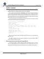
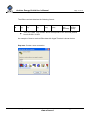
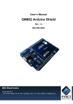
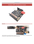
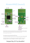
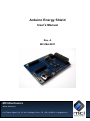
Arduino Energy Shield
User’s Manual
Rev. A
MCI-MA-0087
MCI Electronics
www.olimex.cl
Luis Thayer Ojeda 0115. Of. 402 ▪ Santiago, Chile ▪ Tel. +56 2 3339579 ▪ [email protected]
MCI Ltda.
Luis Thayer Ojeda 0115. Of. 402
Santiago, Chile
www.olimex.cl
Tel: +56 2 3339579
Fax: +56 2 3350589
® MCI Ltda. 2011
Attention: Any changes and modifications done to the device will void its warranty
unless expressly authorized by MCI.
Manual Code: MCI – MA - 0087
Arduino Energy Shield User’s Manual
Page 3 of 16
CONTENTS
CONTENTS ............................................................................................................ 3
INTRODUCTION .................................................................................................... 4
GENERAL FEATURES ........................................................................................... 5
DEFINITIONS ......................................................................................................... 5
SHIELD PARTS ...................................................................................................... 6
SHIELD INSTALLATION ......................................................................................... 8
PORT MAPPING .................................................................................................. 10
ELECTRICAL CHARACTERISTICS ..................................................................... 10
MECHANICAL CHARACTERISTICS .................................................................... 10
REAL TIME CLOCK CONFIGURATION ............................................................... 11
ENERGY SENSING .............................................................................................. 12
NOTES ................................................................................................................. 15
MAINTENANCE .................................................................................................... 15
DOCUMENT HISTORY ........................................................................................ 16
Luis Thayer Ojeda 0115 Of. 402 ▪ Santiago, Chile ▪ Tel. +56 2 3339579 ▪ [email protected]
www.olimex.cl
Arduino Energy Shield User’s Manual
Page 4 of 16
INTRODUCTION
Arduino Energy Shield is a board which enables you to monitor your house, office,
installation or any other equipment energy consumption, directly with your Arduino
board, without the need of wiring, using the XBee wireless communication link. Arduino
Energy Shield integrates the ADE7753 chip which allows to sense active power,
reactive power, RMS voltage and current, among other variables, at a given time.
Arduino Energy Shield is compatible with Arduino Duemilanove, Uno and Mega
boards.
The Arduino Energy Shield has an embedded real time clock, which allows adding the
date and time to the sensed data and sending it to another device for its post
processing and visualization. It also has a coin type battery socket, as a backup power
supply for the real time clock.
The Arduino Energy Shield also has an onboard socket for XBee/XBee Pro, for
transmitting data to other devices, without the need of wiring from the sensing place to
the storage, processing and visualization equipment of the data sensed by the Arduino
Energy Shield.
The Arduino Energy Shield comes with complete function libraries, useful to make any
kind of operations with the probes, like calibration tasks or getting the sensed data.
Function Libraries for communication with the real time clock are also included.
Luis Thayer Ojeda 0115 Of. 402 ▪ Santiago, Chile ▪ Tel. +56 2 3339579 ▪ [email protected]
www.olimex.cl
Arduino Energy Shield User’s Manual
Page 5 of 16
GENERAL FEATURES
Active and apparent power measurement.
RMS voltage and current measurement.
Operation range from 0[V] to 220[V].
30[A] maximum current.
Temperature sensor measurement range from -25°C to 80°C, with 3°C
precision.
Sensor input
o Voltage input: 12VAC
o Current input: 20mA max.
Opto-isolated pulse output, with frequency proportional to watt-hour
measurements.
12mm Coin type battery socket.
Real time clock.
o IC DS1307.
o 32kHz clock.
Arduino reset button.
5 VDC power supply.
XBee/XBee Pro socket.
Galvanically isolated probe connectors.
DEFINITIONS
RSSI: Receive Signal Strength Indicator.
XBee: 2.4 GHz wireless communication module. It supports point-to-point,
point-to-multipoint and mesh networks.
Real Time Clock (RTC): Exact time counter integrated circuit. The RTC
included with the Arduino Energy Shield gives both the time and date, among other
features that can be accessed with the included function library.
Pulse output: Old analog sensors had a rotating wheel: a certain amount of
turns represented 1kWh. In Arduino Energy Shield this feature is still available due
to the pulse output feature, which is optically connected to the internal circuitry.
Luis Thayer Ojeda 0115 Of. 402 ▪ Santiago, Chile ▪ Tel. +56 2 3339579 ▪ [email protected]
www.olimex.cl
Arduino Energy Shield User’s Manual
Page 6 of 16
SHIELD PARTS
Pulse LED
XBee
module
Pulse
output
LED RSSI
LED
Data in
Voltage
probe
LED
Data out
Battery
socket
Current
probe
Reset
button
Fig.1 Arduino Energy Shield top view.
XBee module: XBee socket for its installation.
LED RSSI: XBee module Received Signal Strength Indicator LED.
LED Data in: Data received LED indicator. If it is on, the XBee module is
receiving data.
LED Data out: Data transferred LED indicator. If it is on, the XBee module
is transmitting data.
Battery socket: Coin type Lithium battery socket. Its main functionality is
to maintain the real time clock on, even if the board is de-energized.
Reset: Arduino reset button.
Pulse LED: LED which blinks with a frequency proportional to the
consumption. This frequency depends on the constant parameter set in the
probe. The Arduino Energy Shield gives 32000 pulses/kWh.
LED PWR: Energized board LED indicator.
o
On: Energized board.
Luis Thayer Ojeda 0115 Of. 402 ▪ Santiago, Chile ▪ Tel. +56 2 3339579 ▪ [email protected]
www.olimex.cl
Arduino Energy Shield User’s Manual
o
Page 7 of 16
Off: De-energized board.
Pulse output: Opto-isolated output. It can be used for calibration or to do
monitoring tasks.
Voltage probe: Voltage probe terminal block connector 12VAC.
Current Probe: Current probe terminal block connector. The module was
designed to be used with a 20mA max. non-invasive AC current sensor
which works by sensing the electromagnetic generated by the current flow
in a conductor. This is why it is not necessary to interrupt the circuit for
measurements.
Luis Thayer Ojeda 0115 Of. 402 ▪ Santiago, Chile ▪ Tel. +56 2 3339579 ▪ [email protected]
www.olimex.cl
Arduino Energy Shield User’s Manual
Page 8 of 16
SHIELD INSTALLATION
To connect the Arduino Energy Shield to the base board (Duemilanove, Mega
or Uno), a few steps must be followed:
A. Place the XBee radio on its socket, according to the silkscreen
orientation.
B. Insert the Coin type Lithium battery in its socket.
C. Connect the current probe to the corresponding terminals.
D. Connect the voltage probe to the corresponding terminals.
E. Place the shield over the Arduino main board as shown in figure 2. It is
important to mention that the pin headers that connect the shield with
Arduino have only one position.
F. Assemble the Arduino Energy Shield with the Arduino main board.
G. Connect the Arduino main board to the PC by using a USB cable.
Luis Thayer Ojeda 0115 Of. 402 ▪ Santiago, Chile ▪ Tel. +56 2 3339579 ▪ [email protected]
www.olimex.cl
Arduino Energy Shield User’s Manual
Page 9 of 16
D
A
C
F
E
B
G
Fig.2 Arduino Energy Shield assembly.
Luis Thayer Ojeda 0115 Of. 402 ▪ Santiago, Chile ▪ Tel. +56 2 3339579 ▪ [email protected]
www.olimex.cl
Arduino Energy Shield User’s Manual
Page 10 of 16
PORT MAPPING
The I/O ports used by the Arduino Energy Shield can’t be used by another
shield, with the exception of SDA, SCL and RESET signals.
Pin
DIGITAL 0
Name
Serial RX
DIGITAL 1
Serial TX
DIGITAL 2
DIGITAL 3
DIGITAL 10
DIGITAL 11
DIGITAL 12
DIGITAL 13
ANALOG 4
ANALOG 5
SoftSerial RX
SoftSerial TX
CHIP SELECT
DATA IN
DATA OUT
SIGNAL CLOCK
I2C RTC SDA
I2C RTC SCL
Function
Hardware connection to Rx Serial Port pin. Not
used.
Hardware connection to Tx Serial Port pin. Not
used.
Software connection to Rx Serial Port pin.
Software connection to Tx Serial Port pin.
For enabling probe communication.
Probe communication input data.
Probe communication output data.
Probe communication clock signal.
I2C clock communication data.
I2C clock communication signal.
ELECTRICAL CHARACTERISTICS
5 VDC power supply.
12mm 3V Coin type battery socket.
Average consumption: 5.4mA without XBee module, 52.4mA with
connected XBee module.
MECHANICAL CHARACTERISTICS
Dimensions (WidthxLengthxHeight) 54x69x12 [mm]
Luis Thayer Ojeda 0115 Of. 402 ▪ Santiago, Chile ▪ Tel. +56 2 3339579 ▪ [email protected]
www.olimex.cl
Arduino Energy Shield User’s Manual
Page 11 of 16
REAL TIME CLOCK CONFIGURATION
To configure the Arduino Energy Shield real time clock, the Arduino sketch
“Configure.pde” has to be used. You can download it from the product’s website at
http://www.olimex.cl.
When running the sketch, the command line will ask for the actual date first, and
then for the time. These parameters will be used to configure the clock.
An example of the sketch output by the Arduino IDE command line is shown
below:
Luis Thayer Ojeda 0115 Of. 402 ▪ Santiago, Chile ▪ Tel. +56 2 3339579 ▪ [email protected]
www.olimex.cl
Arduino Energy Shield User’s Manual
Page 12 of 16
ENERGY SENSING
After installing the Arduino Energy Shield and configuring its real time clock, as
explained before, the energy sensing process can be started.
First you have to load the sketch “demo.pde” on the Arduino board. This sketch
includes all the necessary things to sense temperature, current, voltage, active and
reactive energy and also to read the actual time and date from the real time clock.
Then all this data can be sent to other devices through the XBee wireless link and
also through the Arduino board hardware Serial Port.
The following image is a screenshot of the sketch command line output, sensing
a load which consumes about 500 mA @ 220V.
=====11/01/2011 - 16:29:35=====
Fecha: 11/01/2011
Hora: 16:29:35
Hora unix: 1294777775
voltaje [V]: 1401965 | 1403679 | 221 | 216 | 218 | 220
corriente [mA]: 125528 | 125310 | 496 | 496 | 496 | 495
Consumo: 95
Consumo aparente: 101
Energia act: 95 | 100
Energia apa: 2860 | 2861
Temperatura: 22 | 22 | 22 | 23
mode: 8
There is also a function library developed by MCI Electronics, for controlling the
ADE7753 chip.
The XBee modules must be properly configured to ensure effective XBee
communications between modules.
Receiving data from the Arduino Energy Shield
To receive the data, an XBee Explorer module connected to the PC can be
used. The XBee Explorer has to be treated like it was a normal Serial Port. This
could be done with Hyper Terminal. An example of this is detailed in next section.
Luis Thayer Ojeda 0115 Of. 402 ▪ Santiago, Chile ▪ Tel. +56 2 3339579 ▪ [email protected]
www.olimex.cl
Arduino Energy Shield User’s Manual
Page 13 of 16
The XBee received data has the following format:
Probe
ID
Time
[s]
Temperature
[°C]
Voltage
[V]
Current
[mA]
Active Power
[Wh]
Consump
tion
[W/3600]
Apparent
Energy
[VAh]
Time is in UNIX Time format, which corresponds to the seconds passed
from 0:00:00 1/1/1970.
An example of how to receive XBee data with HyperTerminal is shown below:
Step one: Create a new connection.
Luis Thayer Ojeda 0115 Of. 402 ▪ Santiago, Chile ▪ Tel. +56 2 3339579 ▪ [email protected]
www.olimex.cl
Arduino Energy Shield User’s Manual
Page 14 of 16
Step two: Select the serial port.
Step three: Configure the connection as follows:
Luis Thayer Ojeda 0115 Of. 402 ▪ Santiago, Chile ▪ Tel. +56 2 3339579 ▪ [email protected]
www.olimex.cl
Arduino Energy Shield User’s Manual
Page 15 of 16
Step four: The XBee received data will be shown in the command line.
NOTES
The module was NOT designed to be used directly with 220V due to the risks
for both the equipment and people. To provide galvanic isolation, appropriate
voltage and current probes must be used.
MAINTENANCE
The Arduino Energy Shield does not require major maintenance; you just have
to change the battery from time to time. Under normal conditions the battery will last
for 235.000 hours, so it has to be changed every 5 years or when it runs out of
power. If the backup battery is not connected and the device is de-energized, it will
lose its time configuration.
Luis Thayer Ojeda 0115 Of. 402 ▪ Santiago, Chile ▪ Tel. +56 2 3339579 ▪ [email protected]
www.olimex.cl
Arduino Energy Shield User’s Manual
Page 16 of 16
DOCUMENT HISTORY
Revision
1.0
Date
February 10, 2011
Edited by
S. Derteano
Description/Changes
Initial document version
Luis Thayer Ojeda 0115 Of. 402 ▪ Santiago, Chile ▪ Tel. +56 2 3339579 ▪ [email protected]
www.olimex.cl