1
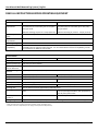
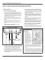
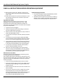
USER
MANUAL
MODEL NUMBER:
FOG-IT6
FG-NA-N130
FG-NA-26SS
AND RELATED ITEMS
Wall-Mounted Fog System
English (Original Instructions)
User Manual: Wall-Mounted Fog System | English
READ ALL INSTRUCTIONS BEFORE OPERATING EQUIPMENT
WARNING
OPTIONS
Pump Seal Material
Control box
Santoprene (standard)
FOG-IT6
Viton (V)
Kalrez (K)
Read this manual completely and understand the
machine before interacting with it.
Add bold option codes to item number as
shown. For standard options, no option code
is needed.
Examples:
• Read all instructions before installing or operating unit.
• Always wear appropriate personal protective equipment
(PPE) when operating or servicing unit.
• Always follow all chemical safety precautions and
handling instructions provided by the chemical
manufacturer and Material Safety Data Sheet (MSDS).
• Fogging with chemical products can be hazardous.
Know the hazards of your chemical products prior to
use. Wear appropriate personal protective equipment
and follow all instructions and safety precautions in
accordance with the MSDS for your chemical product.
• FOG-IT6 (standard unit with Santoprene
pump seals)
• FOG-IT6V (unit with Viton pump seals)
Nozzle
assemblies
FG-NA-N130
FG-NA-26SS
• If this unit is modified or serviced with parts not listed in
this manual, the unit may not operate correctly.
• Before performing any maintenance on this unit,
disconnect the unit from the electrical power source
and compressed air supply, and open the air purge valve
(QFSOV38) to release any air pressure stored in the
system.
• Do not exceed an incoming air pressure of 150 psi (10.3
bar).
• Do not exceed a fluid temperature of 100˚F (37˚C).
• Only use clean and dry air. Air must be filtered and free
of moisture or pump life will be diminished. If needed,
install a water separator (WS-20CFM) before unit.
• Do not use an air lubricator before the unit.
• Never use unit if it is damaged or leaking.
• Disconnect unit from electrical power source before
servicing.
PROTECT THE ENVIRONMENT
Please dispose of packaging materials, old machine
components, and hazardous fluids in an environmentally safe
way according to local waste disposal regulations.
Always remember to recycle.
Specifications and parts are subject to change without notice.
Model No.: FOG-IT6, FG-NA-N130, FG-NA-26SS, AND RELATED ITEMS
Page 2 of 8 | 05152014
User Manual: Wall-Mounted Fog System | English
READ ALL INSTRUCTIONS BEFORE OPERATING EQUIPMENT
REQUIREMENTS
Compressed air
requirements
WITH FG-NA-N130 NOZZLES:
WITH FG-NA-26SS NOZZLES:
At factory air pressure setting of 50 psi (3.4 bar): 2
cfm (56.6 l/min) for control box, plus 2.5 cfm (70.8
l/min) per nozzle
At factory air pressure setting of 50 psi (3.4 bar): 2
cfm (56.6 l/min) for control box, plus 5 cfm (142 l/
min) per nozzle
Maximum incoming air pressure: 150 psi (10.3 bar)
Maximum incoming air pressure: 150 psi (10.3 bar)
Liquid temperature
range
40-100˚F (4.4-37˚C)
Electrical
requirements
120 VAC at 60 Hz, 2 amps (GFCI protected outlet)
Operating voltage
120 VAC
Chemical
compatibility
Chemical products used with this equipment must be formulated for this type of application and
compatible with unit materials and pump seals. For more information on chemical compatibility, consult
the manufacturer or MSDS for your product.
SPECIFICATIONS
WITH FG-NA-N130 NOZZLES:
WITH FG-NA-26SS NOZZLES:
Power type
Compressed air, electricity
Chemical pickup type
Draws from pre-mixed solution
Number of products
unit can draw from
One product
Suction line length/
diameter
8 ft. (2.4 m) hose with 3/8 in. (9.5 mm) inside diameter)
Flow rate*
7.9 oz/min (0.23 l/min)
Pump seals
Santoprene, Viton, or Kalrez
Nozzle construction
Polypropylene and kynar
Timer operation type
Delay on make single shot
Droplet size
15 micron at 50 psi (3.4 bar)
Coverage area
1 liter of solution will cover approximately 1000 cubic feet**
Coverage pattern
Flat pattern with projection up to 10 ft. (3 m) from
nozzle
Pattern up to 8 ft. (2.4 m) wide (side to side) and 3
ft. (0.9 m) thick (top to bottom), with projection up
to 15 ft. (4.6 m) from nozzle
Number of
nozzles***
1-20 nozzles per control box
1-12 nozzles per control box
Tubing/fitting sizes
Designed for use with 3/8 in. (9.5 mm) outside diameter tubing between control box and nozzle(s)
5.3 oz/min (0.16 l/min)
Celcon, stainless steel, EPDM and nylon
35 micron at 50 psi (3.4 bar)
*Dilution rates and flow rates given are based on chemical with viscosity of water and factory air pressure settings.
**Area covered and run time may vary based on humidity, air flow, and product used.
***Number of nozzles is dependent upon air supply (see Compressed Air Requirements)
Model No.: FOG-IT6, FG-NA-N130, FG-NA-26SS, AND RELATED ITEMS
Page 3 of 8 | 05152014
User Manual: Wall-Mounted Fog System | English
READ ALL INSTRUCTIONS BEFORE OPERATING EQUIPMENT
Installation Instructions
1. Remove all components from packaging.
2. Select an area to mount the control box.
Note: The control box should be mounted to a vertical
wall. We recommend mounting the control box at a height
of 6 ft. (1.8 m) or less. The chemical suction line must
reach the bottom of the chemical container. The bottom
of the chemical container should not be positioned higher
than the bottom of the control box.
3. Attach the control box mounting feet to the back of the
control box, using the four screws provided in the parts
package.
4. Mount the control box to the wall using the four screws
and plastic anchors provided in the parts package.
Note: To drill holes for the plastic anchors, use a 5/16 inch
drill bit.
5. Install the air purge valve (QFSOV38) and tee fitting
(QFT38) as shown in the diagram.
AIR PURGE SYSTEM DIAGRAM
SOLUTION
OUT
AIR
OUT
9. When you reach the last nozzle, either plug the air and
solution outlet fittings, or loop the air and solution lines
from the last nozzle back into the system.
Note: Depending on your configuration, plugs (QFP38),
additional tee fittings (QFT38) and/or additional tubing
(H38CP) may be required to complete the installation.
10.With the air inlet valve (HV60-H) in the closed position,
connect a compressed air line to the air inlet fitting
(SSE12). The air inlet fitting is 1/2 in. FPT.
11.Set the timer (TRDU120) for the desired delay time and run
time, as described in the timer adjustment instructions.
TIMER ADJUSTMENT INSTRUCTIONS
AIR
PURGE
The TRDU120 is a
multifunction timer.
QFSOV38
TO
NOZZLES
8. Run tubing (H38CP) from the air outlet (QF1238) on the
control box to the air inlet fitting on a nozzle assembly.
Then run tubing from the air outlet fitting on the original
nozzle to the air inlet fitting on the next nozzle. Repeat as
needed for multiple nozzles.
Note: The air and solution lines must be routed to the
appropriate fittings (as labeled), or the fog quality of the
unit will be negatively impacted. Make sure to insert
the tubing all the way into the fittings to ensure proper
connection.
QFT38
To set the timer:
1. The five “MODE”
switches (A-E) in the
bottom left corner set
the timer function. For
fogging applications,
switch A and switch D
should be ON, and the
other switches (B, C, and
E) should be OFF. This
puts the timer in Dual
Mode, with the 1st Delay
functioning as a delay
time, and the 2nd Delay
functioning as a singleshot run time.
2.
The remaining three switches in the bottom row set the time
interval. One switch lets you choose MIN (minutes) or SEC
(seconds). The other two switches let you select a multiplier
(x0.1, x1, x10, or x100), which can increase or reduce the total
active time.
3.
The switches in the upper column control the active time. In Dual
Mode, the top 5 switches control the 1st Delay (delay time), and
the lower 5 switches control the 2nd Delay (run time). The active
time for each function is equal to the total of the numbers next to
any of these switches that are ON, times the selected multiplier.
6. Mount the fog nozzle assembly (FG-NA-N130, FG-NA-26SS)
in the desired location, using the included screws and
plastic anchors. Repeat as needed for multiple nozzles.
7. Run tubing (H38CP) from the tee fitting (QFT38) to the
solution inlet fitting on a nozzle assembly. Then run tubing
from the solution outlet fitting on the original nozzle to the
solution inlet fitting on the next nozzle. Repeat as needed
for multiple nozzles.
Model No.: FOG-IT6, FG-NA-N130, FG-NA-26SS, AND RELATED ITEMS
Page 4 of 8 | 05152014
User Manual: Wall-Mounted Fog System | English
READ ALL INSTRUCTIONS BEFORE OPERATING EQUIPMENT
12.With the power switch (TS2, TS2PLATE, TSBT12) in the
OFF position, plug the unit into a GFCI protected 120 VAC
power outlet.
Troubleshooting Instructions
13.Follow all instructions from chemical manufacturer. Place
the chemical suction line into a container of pre-mixed
chemical solution.
Operation Instructions
• If air passes through the pump (P56/P56K/P56V) without
cycling, the pump needs to be replaced.
• Check the chemical suction line and strainer for debris or
damage. Clean or replace as needed. To prevent damage
to the unit, the strainer (STR14) must always be used.
Fogging with chemical products can be hazardous. Know
the hazards of your chemical products prior to use. Wear
appropriate personal protective equipment and follow all
instructions and safety precautions in accordance with the MSDS
for your chemical product.
1. Prepare the area to be fogged.
2. Verify the delay time and run time settings on the timer
(see Timer Adjustment Instructions).
3. Make sure the air inlet valve (HV60-H) is open, and the air
purge valve (QFSOV38) is closed.
4. Turn the power switch (TS2, TS2PLATE, TSBT12) to the ON
position.
5. To activate the unit, push the green button (BUT78GR).
The unit will begin cycling through the delay and run time
intervals set on the timer, beginning with the delay time.
6. At the end of the run time, the unit will shut off. Observe
appropriate safety precautions when reentering the area,
in accordance with the MSDS for your chemical product.
7. Turn the power switch (TS2, TS2PLATE, TSBT12) OFF to
prevent unwanted activation of the unit
8. With the air inlet valve (HV60-H) in the open position,
open the air purge valve (QFSOV38) to clear any solution
from the lines. Close the air purge valve (QFSOV38) after
all solution has been cleared from the system.
Maintenance Instructions
To keep your fog unit operating properly, periodically perform
the following maintenance procedures:
Note: Before performing any maintenance, disconnect the unit
from the electrical power source and compressed air supply, and
open the air purge valve (QFSOV38) to release any air pressure
stored in the system.
• Inspect the pump (P56/P56K/P56V) for wear and leaks.
• Inspect all hoses for leaks or excessive wear. Make sure all
hose clamps and push-fittings are in good condition and
properly secured.
• Check the chemical suction line and strainer for debris and
clean as needed.
• Drain your air compressor tank on a regular basis to help
extend pump life. An air source with a high moisture
content will accelerate pump wear. Note: If your air source
has a high moisture content, you may wish to install a
water separator (WS-20CFM) before the unit.
Model No.: FOG-IT6, FG-NA-N130, FG-NA-26SS, AND RELATED ITEMS
Page 5 of 8 | 05152014
User Manual: Wall-Mounted Fog System | English
READ ALL INSTRUCTIONS BEFORE OPERATING EQUIPMENT
CONTROL BOX ASSEMBLY
Inside View
TRDU120
CC8463
TS2, TS2PLATE, TSBT12
P56, P56K or P56V
P56-BRKT
P56-BRKT-SCREW
FW38
PL-G
TIMER
R38
AG100
BA38
SSE12
WC14BC
HV60-H
H14B-H
(Available per .)
WR1A
SSC38
CV38
EC14-2
HHSB1214
BA38
SSC38
BEL38M38M
HBF3812
HHSB1238
QF1238
ACV3D
H38B-H
CC3224
(Available per .)
SHW3
HBSS1238
HB1438
SST12
STR14
CONTROL BOX ASSEMBLY
Outside View
PL-G
OPTIONAL COMPONENT
CC3224
TS2, TS2PLATE, TSBT12
BUT78GR
FW38
SSE12
HV60-H
BN3838
HHSB1238
Model No.: FOG-IT6, FG-NA-N130, FG-NA-26SS, AND RELATED ITEMS
WATER SEPARATOR
Item Number: WS-20CFM
Page 6 of 8 | 05152014
User Manual: Wall-Mounted Fog System | English
READ ALL INSTRUCTIONS BEFORE OPERATING EQUIPMENT
NOZZLE ASSEMBLY
Item Number: FG-NA-N130
QFT38
(Included in parts package)
QF1438
SSA14
FWLG14
SSLB 14
PFN-N130
QF1438
H38CP
(Available per .)
QFT38
NOZZLE ASSEMBLY
Item Number: FG-NA-26SS or FOG-IT6-NP
QF1438
SSLB 14
T14B
TW916
QFT38
H38CP
SSA14
QF1438
(Available per .)
PHC14
PFN26-SS
BEL14M14M
Model No.: FOG-IT6, FG-NA-N130, FG-NA-26SS, AND RELATED ITEMS
Page 7 of 8 | 05152014
User Manual: Wall-Mounted Fog System | English
READ ALL INSTRUCTIONS BEFORE OPERATING EQUIPMENT
ITEM NUMBER
DESCRIPTION
PB16138-GSKT
NEOPRENE GASKET 0.220 INCH ROUND CORD STOCK
ACV3D
1/2 DEMA AIR SOLENOID, BRASS - 120v - 31gpm
PB16138-LATCH
LATCH FOR PB16138
AG100
1.5 INCH DRY MODEL 20 DUAL SCALE GAUGE
PB16138-PIN
B103225
10-32 X 1/4in PHIL MACH SCREW 18-8
STAINLESS STEEL HINGE PIN FOR CONTROL BOX
PB16138 - 1/8 x 4 3/4 x 1/2inches
BA38
3/8 MPT X 3/8 FPT ADAPTOR
PBFT-PP
MOUNTING FEET FOR POLYBOX - PB16138 POLYPROPYLENE
BEL14M14M
BRASS ELBOW 1/4in MPT X 1/4in MPT
PFN26-SS
BEL38M38M
BRASS ELBOW 3/8in MPT X 3/8in MPT
PNEUMATIC FOG NOZZLE WITH STAINLESS STEEL TIP
- HIGH FLOW
BN3838
BRASS HEX NIPPLE 3/8in X 3/8in
PFN-N130
Pneumatic Fog Nozzle(1/4QMJ+SUQF-N130
ASSEMBLED) - Polypropylene and KYNAR
BUT78GR
PB OPR NO CB
PHC14
BLACK POLY HOSE CLAMP
CC3224
LTC BLACK 1/2 NPT
PL16138
CC8463
1/2in NPT BLACK LOCKNUT
CONTROL BOX LID - POLYPROPYLENE - 16x13x8 HINGED LOCKABLE LID
CV38
PVC CHECK VALVE 3/8 BARBS - SS SPRING
PL-G
GREEN PILOT LIGHT - MC GILL
EC14-2
OETIKER CLAMP 13.8
QF1238
MALE CON. 3/8in TUBE X 1/2in MPT POLYPROPYLENE
FW38
.687 ID X 1-1/2 OD X .07 TK FLATWASHER (5/8) 18-8
QF1438
FWLG14
.569 ID X 1.28 OD X .08 THICK FLAT WASHER SS 18-8
MALE CON. 3/8in TUBE X 1/4in MPT POLYPROPYLENE
H14B-H
1/4 INCH BLUE HOSE- GOODYEAR HORIZON Available per ft.
QFSOV38
SHUT OFF VALVE 3/8in TUBE POLYPROPYLENE
QFT38
UNION TEE 3/8in TUBE POLYPROPYLENE
3/8 INCH BLUE GOODYEAR HORIZON HOSE - Available
per ft.
R38
CFDR60-3NG FILTER, REG 3/8in
S1034FHL
10 X 3/4 PHIL FLAT HI-LO THRD SCREW 18-8
H38B-H
H38CP
3/8 IN OD POLYETHYLENE TUBING - NATURAL Available per ft.
SHW3
3in LONG COATED WEIGHT
HB1438
1/4in MPT X 3/8in HOSE BARB (PLASTIC)
SN1212
1/2in HEX STAINLESS STEEL NIPPLE
HBB1414
BRASS 1/4 X 1/4 HOSE BARB
SSA14
SS304 MALE/FEMALE ADAPTOR 1/4 NPT X 1/4 NPT
HBF3812
HOSE BARB 3/8 X FEMALE PIPE THREAD 1/2 IN
SSC38
WORM GEAR CLAMP, S/S (.25-.63)
HBSS1238
STAINLESS HOSE BARB 1/2mpt X 3/8 barb
SSE12
STREET ELBOW 1/2in - 316 S.S.
HBSSEL1438
STAINLESS HOSE BARB ELBOW 1/4 INCH NPT X 3/8
HOSE BARB
SSLB 14
14GA SS BRACKETS W/SLOTS
HHBB1418
HEX HEAD BRASS BUSHING 1/4in X 1/8in
SST12
1/2in FPT 304 S.S. TEE
HHSB1214
HEX HEAD S.S. REDUCER BUSHING 1/2 X 1/4
STR14
40 MESH SUCTION LINE STRAINER 1/4 MNPT
HHSB1238
HEX HEAD S.S. REDUCER BUSHING 1/2in X 3/8
T14B
FEMALE BRASS TEE 1/4in
HV60-H
1/2” S.S. BALL VALVE W/ STRAIGHT HANDLE W/O
WELD
TRDU120
120 VOLT MULTI-FUNCTION TIME RELAY
TRS11
11 PIN MAGNAL SOCKET
P56
5700 PUMP WITH SANTOPRENE SEALS - INCLUDES
HOSE BARBS, AIR FITTING, AND AIR PORT
TS2
TOGGLE SWITCH SPST
P56K
5700 PUMP WITH KALREZ SEALS - INCLUDES HOSE
BARBS, AIR FITTING, AND AIR PORT
TS2PLATE
ON/OFF SWITCH PLATE
TSBT12
TOGGLE SWITCH BOOT
P56V
5700 PUMP WITH VITON SEALS - INCLUDES HOSE
BARBS, AIR FITTING, AND AIR PORT
TW916
1/2 INT TOOTH L/W 410SS
20756103B
WC14BC
BUTT CONNECTOR
Polypro G57 Air Port x HB Straight, w/ Viton o-ring
HB14P
WC14FRK
1/4in BRASS HB AIR FITTING /G57/P56 14-16 - INSULATED NARROW FORK TERM.
CONNECTOR
HB5638
HOSE BARB FOR P56 PUMP
WCB14F
14-16 - 1/4 FEM INSULATED CONNECTOR
HB5638K
HOSE BARB FOR P56K PUMP
WCB14FY
10-12 - 1/4in FEMALE INSULATED CONNECTOR
HOSE BARB FOR P56V PUMP
WMS14
14 X 1 1/4 HEX W/H SMS SLOTT, S/S
PUMP BRACKET- STAINLESS STEEL
WMS14A
5/16 X 1 1/2 STRAIGHT PLASTIC ANCHOR
P56-BRKT-SCREW
HI LO SCREW FOR RETAINING P56-BRKT
WR1A
18/3 SJOOW 90 BLACK N.A. W/ 5-15P & 7in ROJ
PB16138
POLYPROPYLENE CONTROL BOX - WORKING DIMS
16x13x8 - PUMP MOUNT
WS-20CFM
TSUNAMI WATER SEPARATOR/AIR DRYER 20 CFM
HB5638V
P56-BRKT
Model No.: FOG-IT6, FG-NA-N130, FG-NA-26SS, AND RELATED ITEMS
Page 8 of 8 | 05152014