1
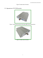
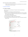
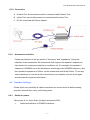
F10F Series
Wide band booster
User’s Manual
F10F Series Booster User’s Manual
Directory
1.
Abbreviations __________________________________________________________ 2
2.
Safety Warnings _______________________________________________________ 2
3.
Application____________________________________________________________ 3
4.
Introduction ___________________________________________________________ 4
5.
System Characteristics __________________________________________________ 5
6.
5.1.
Features __________________________________________________________________ 5
5.2.
Appearance of F10F single system boosters _____________________________________ 5
5.3.
Appearance of F10F-DB boosters______________________________________________ 6
Installation ____________________________________________________________ 7
6.1.
Note about installation _______________________________________________________ 7
6.2.
Antenna Installing and Cable Wiring ____________________________________________ 9
6.2.1.
6.2.2.
6.2.3.
6.2.4.
6.3.
Booster Installation ________________________________________________________ 10
6.3.1.
6.3.2.
6.3.3.
6.4.
Panel antenna Installing ______________________________________________________________9
Directional YAGI antenna Installing _____________________________________________________9
The cable connection confirmation______________________________________________________9
The connectors connection confirmation________________________________________________ 10
Method of Installation _______________________________________________________________ 10
Connection ________________________________________________________________________ 11
Accessories selection _______________________________________________________________ 11
Repeater Settings __________________________________________________________11
6.4.1.
6.4.2.
6.4.3.
Switch on power____________________________________________________________________ 11
Manual Gain Control (MGC) __________________________________________________________ 13
Repeater Commissioning ____________________________________________________________ 14
7.
Installation Procedure __________________________________________________ 16
8.
Troubleshooting _______________________________________________________ 17
-1-
F10F Series Booster User’s Manual
1. Abbreviations
BTS
Base Transceiver Station
DCS
Digital Cellular Service
GSM
Global System for Mobile Communications
MS
Mobile Station
DB
Dual Band
RF
Radio Frequency signals
UL
Uplink (Communication channel from mobile device to cell tower)
DL
Downlink (Communication channel from cell tower to mobile device)
Donor
Outdoor Antenna
LED
Light Emitting Diode
2. Safety Warnings
Users must follow the below principles
?
Booster should follow system requirement of communication equipment,
assure good groundings and lightning protection.
?
The power supply voltage of booster should meet the standards of
security requirement; any booster-operator can operate only after cutting
power in advance. Only the professional can operate electrified.
?
Do not dismantle machine, maintain or displace accessories by yourself,
because in this way, the equipment may be damaged or even get an
electric shock.
?
Do not open the booster; touch the module of booster, even not to open
the cover of module to touch the electronic component, the components
will be damaged due to electrostatic.
?
Please keep away from heating -equipment, because the booster will
dissipate heat when working. And do not cover booster with anything that
influences heat-dissipation.
-2-
F10F Series Booster User’s Manual
3. Application
The mobile devices (Mobile phone, data card, modem, etc.) must connect with BTS
wirelessly; otherwise they couldn’t communicate smoothly, if they can’t get any signals or
only get weak signals in areas that are blocked by buildings, building structures, mountains,
and forests and so on.
Smooth communication
No communication
Booster is used to set up a “bridge” between the base station and the mobile devices,
relaying the signals from BTS to the mobile devices or vise versa, in order to set up a
smooth link again between BTS and the mobile devices.
Booster relays signals
from the mobile devices to BTS
Booster relays signals
from BTS to mobile devices
-3-
F10F Series Booster User’s Manual
4. Introduction
There are millions of very small areas (10~100 square meters) where people work or live in
and suffer from very poor or no mobile signals. People are seeking a cheap and immediate
solution that would allow them has clear phone calls or higher speed broadband. However
most of the current booster solutions usually have larger coverage size, and not cost
effective.
F10F series is specifically designed as a "CHEAP" solution to meet this request.
F10F single system series is supports any one system of GSM900, DCS and WCDMA;
and F10F-DB series is supports any two system of GSM900, DCS, WCDMA.
F10F series is quite elegant metal design and can be held in palm. The single system size
is only 95*129*30mm; and the dual system is only 156*129*30.The power consumption is
only 8.5W.
Composition of Application System:
1)
Donor antenna: Recommend using wide band panel antenna (7~14dBi gain) or
2)
Yagi antenna, better to use antenna with good direction, high gain, and
decoration shall be considered if it is in urban areas.
Role: It picks up signals from the tower, and sends to the booster through cables,
3)
at the same time, it transmits the amplified mobile signals from the booster to the
tower.
Server antenna: Recommend using whip antenna or indoor panel. Whip
4)
5)
antenna is suitable for wide open areas where the signals can be radiated from
the center to the surroundings, while indoor panel is suitable for those narrow
and long areas, like tunnels, corridors, elevators, etc.
Cables: 3D-FB or 5D-FB coaxial cables.
Power supply: Booster power adapter, a desktop standard. Usually directly
6)
connected to a power outlet. But preferably equipped with an air switch,
groundings, sometimes a surge arrestor shall be connected.
Standard F10F is supplied as a kit, including a donor antenna, a 10 meter long
cable and a whip antenna.
-4-
F10F Series Booster User’s Manual
5. System Characteristics
5.1. Features
? Very cost effective solution for immediate coverage
? Dual System to amplify GSM and DCS systems
? ETSI standards
? Support any cellular devices (voice & data & video)
? SOHO solution for small sized areas
? Power LED for power status
? Universal power range of 100V~264V
? Palm size elegant design and low power consumption
5.2. Appearance of F10F single system boosters
Figure 1 shows the front view (colors may differ from real products).
-5-
F10F Series Booster User’s Manual
Figure 2 Lateral view of booster
5.3. Appearance of F10F-DB boosters
Figure 1 shows the front view (colors may differ from real products).
Figure 2 Lateral view of booster
-6-
F10F Series Booster User’s Manual
6. Installation
6.1. Note about installation
1) The booster’s main function is to improve weak RF signals to an area. A simply
formula: Input power + Gain = Output power. The signal strength from the outdoor
antenna directly affects the efficiency of the indoor coverage. It is very important to
choose the location of the outdoor antenna carefully. With this in mind, it is not
recommended that the donor antenna be installed in an attic.
? Testing the signal strength which receipt from outdoor antenna mounted in
site by mobile phone:
?
Please select the top of the building to install the donor antenna if
the total floors are less than 7, and must select a place like balcony
or platform lower than 7th floor for the donor antenna if the buildings
are over 7 floors.
?
The mobile phone displays full bar signals in site, which the donor
antenna is to be installed.
?
The phone calls or data transmission shall be smooth and stable by
testing for 3 times.
?
As shown from the above illustration, testing the signals from A to E,
and select a best place that displays full bar signals to install the
-7-
F10F Series Booster User’s Manual
donor antenna.
? Installation donor antenna
? Notes:
? Do not install the donor antenna during the rainy day with lightning.
? Please follow the instructions to install the donor antenna.
? It is a must that the waterproof shall be done to connectors of donor
antenna and feeder lines.
? In order to avoid interference, please note that the donor antenna
should be far away from the following objects.
? Metal
? High-voltage line
? RF antenna
? High-voltage transformer
2) Booster is a two-way signal amplifier. So proper isolation between donor antenna and
server antenna is necessary in order to avoid self-oscillation. About the definition for
self-oscillation, take MIC and loudspeaker for example , if it is too close for each other,
it could make big noise. So the booster can run smoothly if the isolation between donor
antenna and server antenna is 15 dB higher than the gain of booster. For example, if
the booster gain is 50 dB, then the isolation between donor antenna and server
antenna should be 65 decibel.
If isolation cannot be achieved by the distance due to the limited conditions, we can use
the roof of the building or other barriers. If the barrier is concrete or brick wall, also donor
antenna and server antenna are in opposite direction, just one floor between up and
down stairs will be able to meet the isolation requirement.
3) Accessories selection: Pay attention to two points during selection the accessory due
to the booster belongs to high frequency communication system: frequency and
impedance. All accessories shall support booster frequencies from feeder line, antenna
and splitter to combiners etc. For example, the booster frequency is GSM900, so all
the accessories must support the GSM900 frequency. And the booster impedance is
50ohm, so the accessories shall all be 50ohm. To use any other impedance of coax will
put an extra load on your booster and shorten its life span.
-8-
F10F Series Booster User’s Manual
6.2. Antenna Installing and Cable Wiring
It is recommended that you mount your donor antenna in a spot that is free of any
immediate obstructions. Making use of a pole or mounting bracket is recommended for
optimum antenna performance.
6.2.1. Panel antenna Installing
6.2.2. Directional YAGI antenna Installing
6.2.3. The cable connection confirmation
? Confirmation the quality of the connection whether it is good or not. Check it by
millimeter
? After tightening the connector, no bending and deformation.
-9-
F10F Series Booster User’s Manual
6.2.4. The connectors connection confirmation
? Please confirm the connectors are very well connected between the donor antenna,
cable, booster and the server antennas.
6.3. Booster Installation
6.3.1. Method of Installation
The F10F can only be mounted indoors. The booster is fixed onto the wall through
expansion bolts.
A. Drill holes on the selected place and install expansion bolts.
B. Align the holes on the installing support with the expansion bolts, keep the installing
support vertical, place flat washers, spring washers, and nuts in turn, and tighten the
nuts to fasten the installing support.
C. Place the booster on the support and fasten it.
D. Connect cables and power cables to the booster respectively.
E. After installing the booster as described as above, power on the booster to check the
operation status.
The figure showing how to install F10F-DB
- 10 -
F10F Series Booster User’s Manual
6.3.2. Connection
A. Outdoor Port: donor antenna cable is connected with Outdoor Port;
B. Indoor Port: service whip antenna is connected with Indoor Port;
C. DC IN: connected with Power adaptor.
6.3.3. Accessories selection
Please pay attention to the two points of “frequency” and “impedance” during the
selection of the accessories. All accessories shall support the repeater’s frequencies
from feeder line, antenna and splitter to combiners etc. For example, the repeater’s
frequency is GSM900, so all the accessories must support the GSM900 frequency. And
the repeater’s impedance is 50ohm, so the accessories shall all be 50ohm . To use any
other impedance of coax will put an extra load on your repeater, shorten its life span
and decrease the system performance.
6.4. Repeater Settings
Please check very carefully all cable connections are correct and firm before running
operation test and then carry out following tests.
6.4.1. Switch on power
After power is on, check firstly the alarm and power LEDs.
?
Status and definition of POWER indicators:
- 11 -
F10F Series Booster User’s Manual
?
Status
Definition
Green
Normal
Off
DC power problem
S
tatus and Definition of ALARM indicators; Alarm LED only works for downlink signals
Status
ALARM
It is working in linearity
Green
Warning: Input signals may be not enough, so please check on
coverage effect, do not do anything if it is good; otherwise please
adjust the repeater system to get better coverage.
A little bit stronger input signals or slight self oscillation have
occurred.
Solution: Please adjust antennas or use MGC to reduce the
Orange
repeater gain, till you find “edge point” with green LED (I.E. the
Alarm LED must stay at green color, and at the edge of turning
Orange), and let the repeater work at this point. MGC is the last
measure to take as it will influence on coverage.
There are strong input signals or severe self oscillation, measures
Red
must be taken (please note that our repeaters have auto shut off
function, so the red color status can only maintain 5 seconds).
Repeater breaks down, or severe self oscillation leads to auto mute. Please
Off
re-plug in and check if alarm LED turns red, if it is, please take measures to
keep alarm LED green; if it maintains off, it means the power break down.
Remark: Please note that Alarm LED works on repeater downlink signals only. I.E.
the repeater input signals from CELL TOWER.
Single system repeater only has one set of power and alarm LEDs, while dual
system have two sets of power and alarm LEDs, and three system repeaters have
three sets of LEDs. Each system has own relevant LED and please refer to the
correct LED for system performance evaluation.
Then repeater with plastic closet is designed with LEDs of “Alarm LOW” and “Alarm
HIGH”. When it is used for single system of CDMA800, GSM850 and GSM900, only
“Alarm Low” LED works, and “Alarm HIGH” LED is no use; when it is used for single
- 12 -
F10F Series Booster User’s Manual
system of DCS, PCS, CDMA1900, WCDMA or AWS, “Alarm HIGH” LED works, and
“Alarm LOW” LED is no use. When the repeater supports two systems, “Alarm Low”
and “Alarm HIGH” both work and support relevant low and high frequencies
DIP Switch can be used to adjust the repeater gain when Alarm LED is orange or even
RED. The principle is that repeater alarm LED must be green color.
6.4.2. Manual Gain Control (MGC)
Switches 1.2 represent Downlink and 3.4
represent Uplink. When it is necessary to
adjust the gain by DIP switch, firstly please
adjust Downlink gain according to input
signals, secondly please adjust Uplink gain
according to Downlink gain.
The DIP Switches have default ‘OFF’ status;
please push relevant switches to “ON”
position if certain attenuation value needs
to be achieved.
?
DIP switch downlink attenuation setting:
Att
0 dB
5 dB
10 dB
15dB
?
1
off
ON
off
ON
2
off
off
ON
ON
DIP switch uplink attenuation setting:
Att
0 dB
5 dB
10 dB
15dB
3
off
ON
off
ON
- 13 -
4
off
off
ON
ON
F10F Series Booster User’s Manual
6.4.3.
Repeater Commissioning
? The curve about device working status
POutput Power
Critical stable point
Pmax
(Pinput Power -VATT)
Green LED linear
amplification area
Orange
Red LED
Equipment
overload zone
Output power, input signal and their attenuation curve
POutput Power: Output Power
Pinput Power: Input Power
VATT: Attenuation value of attenuator
Pinput Power -VATT: Input Power- Attenuation value of attenuator
Pmax: Rate output power
? Downlink gain setting
First the alarm LED only indicates the downlink input power level, here we use color of Alarm LED
to adjust the gain of the repeater. Alarm LED color must remain green. As for the downlink
working performance, it is a good working point that Alarm LED maintains “Green” color with the
intention of turning orange; here we refer as “edge point”. At this time, downlink output power and
coverage effect are stable.
And the equipment must be as far as possible away from overloading status of “red”
- 14 -
F10F Series Booster User’s Manual
(the equipment would hold higher interference and depression ability at this stage).
So we shall try our best to set the equipment near “edge point” of green and intention
of turning orange during engineering.
? Setting of “edge point”:
Switch on the power supply after connection with donor antenna and server antenna, and
observe ALARM LED.
? If it shines “orange”, use 1dB as step to reduce the gain until “green” turns on, then increase
the gain 1~3dB attenuation value until “orange” starts to turn on, then brings back 1~2dB till
“green” is on, then fix the gain and the repeater ’s downlink output power reaches the perfect
status.
? If it shines “green” then.
? Please check coverage effect firstly, if the coverage effect is good, the engineering has
reached expecting target, thus there is no need to do anything.
? To check whether the attenuation value has been set, if it is, use 1dB as step to increase
gain until the “orange” turns on, then brings back 1~2dB till “green” is on again , then the
repeater ’s downlink output power reaches the perfect status.
? But if attenuation has not been set, it indicates that the input power is not strong enough to
let the repeater reach its good coverage.
If the coverage effect is not good, the donor antenna should be adjusted to get stronger
input signal. It is recommended that one person shall check the coverage effect inside
the building when the other person is trying to adjust the antenna or the repeater. At this
stage, please make sure “Orange” color will not be generated by self oscillation. Please
take off the server antenna to check if it is self oscillation or not: if the Orange turns to be
green, it is self oscillation; if it stays as Orange, it is not self oscillation. Please follow steps
in other page to turn Orange to be Green.
? Uplink gain setting
Standard: uplink attenuation values =downlink attenuation values
Remark: Avoid putting more than a 5dB difference between the Uplink and Downlink.
And Uplink gain must be equal to or less than DL gain, it can’t be more in order to
avoid interference with mobile network.
- 15 -
F10F Series Booster User’s Manual
7. Installation Procedure
- 16 -
F10F Series Booster User’s Manual
8. Troubleshooting
Q1. Why is there still no signal after installing the equipment?
Answer:
1. Check the power on booster and power supply.
2. Check the connector of outdoor antenna is tight or not.
3. Check the connectors of RF cable are tight or not.
4. Check the outdoor signal is strong enough or not.
5. Check to make sure the antenna is installed correctly.
6. Check the connector of indoor antenna is tight or not.
7. Check the cable type is suitable or not.
Q2. Why the signal strength is too weak on the edge of area?
Answer:
1. Check the outdoor signal and antenna direction.
2. Check booster is full gain or not.
3. Check all of the connectors are tight.
4. Change the location of outdoor/indoor antenna.
5. Check the cable type is suitable or not.
6. Deploy more indoor antennas.
Q3. After running booster, why the signals are not stable?
Answer:
1. Checking the distance between donor antenna and server antenna are too close to
each other?
2. Checking the signals from donor antenna whether to be stable or not?
3. Connect the system again if it is incorrect connection.
Q4. Why the booster power LED is not bright?
Answer:
1. Checking the input AC power range indicated on power adapter whether is
corresponding to the local power system.
2. Checking the power adapter whether connect the equipment correctly and stably or
not.
3. Checking the power adapter whether damage or not. To test output voltage whether
be corresponding to that indicated on power adapter or not by multimeter.
- 17 -