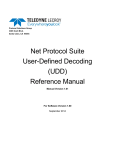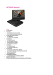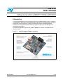
1
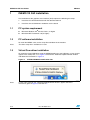
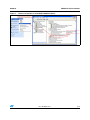
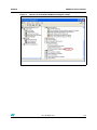
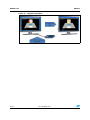
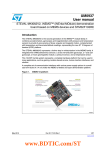
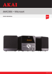
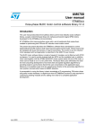
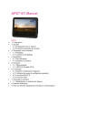
UM1010
User manual
Getting started with the iNEMO™ STEVAL-MKI062V2
Introduction
The STEVAL-MKI062V2 is the second generation of the iNEMO modules family. It combines
accelerometers, gyroscopes, and magnetometers with pressure and temperature sensors to
provide 3-axis sensing of linear, angular, and magnetic motion, complemented with
temperature and barometer/altitude readings, representing the new ST 10-degrees of
freedom (DOF) platform.
This document provides a quick start guide for iNEMO PC software and graphical user
interface (GUI).
Figure 1.
October 2010
STEVAL-MKI06V2 iNEMO V2 platform
Doc ID 18054 Rev 1
1/18
www.st.com
Contents
UM1010
Contents
1
2
iNEMO V2 GUI installation . . . . . . . . . . . . . . . . . . . . . . . . . . . . . . . . . . . . 4
1.1
PC system requirement . . . . . . . . . . . . . . . . . . . . . . . . . . . . . . . . . . . . . . . 4
1.2
PC software installation . . . . . . . . . . . . . . . . . . . . . . . . . . . . . . . . . . . . . . . 4
1.3
Virtual Com driver installation . . . . . . . . . . . . . . . . . . . . . . . . . . . . . . . . . . 4
iNEMO suite . . . . . . . . . . . . . . . . . . . . . . . . . . . . . . . . . . . . . . . . . . . . . . . . 8
2.1
iNEMO suite main window . . . . . . . . . . . . . . . . . . . . . . . . . . . . . . . . . . . . . 9
2.2
Connecting iNEMO . . . . . . . . . . . . . . . . . . . . . . . . . . . . . . . . . . . . . . . . . . 10
2.3
Acquisition settings . . . . . . . . . . . . . . . . . . . . . . . . . . . . . . . . . . . . . . . . . . 12
2.4
Start acquisition and data description . . . . . . . . . . . . . . . . . . . . . . . . . . . 12
2.5
AHRS algorithm starting and settings . . . . . . . . . . . . . . . . . . . . . . . . . . . 13
2.6
AHRS 3D demo . . . . . . . . . . . . . . . . . . . . . . . . . . . . . . . . . . . . . . . . . . . . 14
2.6.1
3
2/18
3D view alignment . . . . . . . . . . . . . . . . . . . . . . . . . . . . . . . . . . . . . . . . . 15
Revision history . . . . . . . . . . . . . . . . . . . . . . . . . . . . . . . . . . . . . . . . . . . 17
Doc ID 18054 Rev 1
UM1010
List of figures
List of figures
Figure 1.
Figure 2.
Figure 3.
Figure 4.
Figure 5.
Figure 6.
Figure 7.
Figure 8.
Figure 9.
Figure 10.
Figure 11.
Figure 12.
Figure 13.
Figure 14.
Figure 15.
STEVAL-MKI06V2 iNEMO V2 platform . . . . . . . . . . . . . . . . . . . . . . . . . . . . . . . . . . . . . . . . 1
STEVAL-MKI062V2 notification icon . . . . . . . . . . . . . . . . . . . . . . . . . . . . . . . . . . . . . . . . . . 4
Manual installation of the STEVAL-MKI062V2 driver . . . . . . . . . . . . . . . . . . . . . . . . . . . . . . 5
iNEMO driver installation . . . . . . . . . . . . . . . . . . . . . . . . . . . . . . . . . . . . . . . . . . . . . . . . . . . 6
How to see the STEVAL-MKI062V2 COM port number . . . . . . . . . . . . . . . . . . . . . . . . . . . 7
Kit selector window . . . . . . . . . . . . . . . . . . . . . . . . . . . . . . . . . . . . . . . . . . . . . . . . . . . . . . . . 9
iNEMO Suite main window . . . . . . . . . . . . . . . . . . . . . . . . . . . . . . . . . . . . . . . . . . . . . . . . . 10
Selected COM port number . . . . . . . . . . . . . . . . . . . . . . . . . . . . . . . . . . . . . . . . . . . . . . . . 10
New data file icon . . . . . . . . . . . . . . . . . . . . . . . . . . . . . . . . . . . . . . . . . . . . . . . . . . . . . . . . 11
How to open the connection . . . . . . . . . . . . . . . . . . . . . . . . . . . . . . . . . . . . . . . . . . . . . . . . 11
Acquisition settings icon . . . . . . . . . . . . . . . . . . . . . . . . . . . . . . . . . . . . . . . . . . . . . . . . . . . 12
Data icon description . . . . . . . . . . . . . . . . . . . . . . . . . . . . . . . . . . . . . . . . . . . . . . . . . . . . . 13
AHRS stabilization . . . . . . . . . . . . . . . . . . . . . . . . . . . . . . . . . . . . . . . . . . . . . . . . . . . . . . . 14
3D cube demo . . . . . . . . . . . . . . . . . . . . . . . . . . . . . . . . . . . . . . . . . . . . . . . . . . . . . . . . . . 15
Alignment procedure. . . . . . . . . . . . . . . . . . . . . . . . . . . . . . . . . . . . . . . . . . . . . . . . . . . . . . 16
Doc ID 18054 Rev 1
3/18
iNEMO V2 GUI installation
1
UM1010
iNEMO V2 GUI installation
The installation of the graphical user interface (GUI) requires the following two steps:
1.1
1.2
1.
Install the PC software delivered with the demonstration kit
2.
Install the virtual COM driver needed to use the board
PC system requirement
●
Microsoft Windows XP® Service Pack 2, or higher
●
Microsoft.NET Framework 2.0 (or higher)
PC software installation
To install the iNEMO suite, run the setup file and follow the instructions.
Note:
The latest setup file is available on st.com.
1.3
Virtual Com driver installation
To install the virtual COM driver, plug the iNEMO board into a free USB port, an icon should
appear in the “Notify Bar”, as in Figure 2. Wait for the “Hardware Update Wizard” window
and follow the instructions in Figure 4.
Figure 2.
Note:
4/18
STEVAL-MKI062V2 notification icon
If, after a few seconds, the “Hardware Update Wizard” doesn`t appear, follow the
instructions given in Figure 3 and then in 4.
Doc ID 18054 Rev 1
UM1010
Figure 3.
iNEMO V2 GUI installation
Manual installation of the STEVAL-MKI062V2 driver
Doc ID 18054 Rev 1
5/18
iNEMO V2 GUI installation
Figure 4.
UM1010
iNEMO driver installation
Once the installation has finished, a COM port number is assigned to the ST virtual COM
driver (Figure 5). Knowledge of this number is required to correctly run the iNEMO GUI.
6/18
Doc ID 18054 Rev 1
UM1010
iNEMO V2 GUI installation
Figure 5.
How to see the STEVAL-MKI062V2 COM port number
Doc ID 18054 Rev 1
7/18
iNEMO suite
2
UM1010
iNEMO suite
The iNEMO suite application allows the user to work both with the iNEMO V1 and iNEMO
V2 platform. At the startup of the application, the kit selector window appears, to choose the
platform used (Figure 6).
The iNEMO suite application is based on the software development kit (SDK)
iNEMO_SDK.dll (for STEVAL-MKI062V1) and iNEMO2_SDK.dll (for STEVAL-MKI062V2).
Only for the STEVAL-MKI062V2 is the iNEMO suite application also a TCP/IP server for
external/remote demo applications; when the server starts, in the log bar a message shows
the availability of the server. Each client may be connected to the server on port
31001(default) to receive data from the device through the iNEMO suite (server).
Every time a client is connected to the server the log bar shows the IP address of the client
just connected.
Each demo (client) could elaborate and show these data. (The structure of the data sample
sent to all clients is the FrameData_t defined in the iNEMO2_SDK.h).
The TCP/IP server may be enabled/disabled from the Tools->Communication->Settings
menu (its state is shown on the status bar below). From this dialog box, the user can change
the communication port (default 31001). Pay close attention to this information in order to
avoid a communication block from an installed firewall.
To run the INEMO suite:
1.
Click on Start > All Programs > STMicroelectronics > iNEMO Suite > iNEMO Suite
Application
2.
Launch the program iNEMO software tool (Goldfish Icon)
3.
At first, the “Kit Selector” window appears (Figure 6). Select STEVAL-MKI062V2
4.
Check that the serial port number is correct (see Figure 5). Otherwise click the refresh
button and choose the right COM port.
It is preferable to connect the iNEMO board to a free USB port before launching the GUI. In
this way, the GUI directly finds the COM port into which the board is plugged.
To change COM port press the “New” button on the toolbar or from the menu File/New and
the kit selector dialog appears.
8/18
Doc ID 18054 Rev 1
UM1010
iNEMO suite
Figure 6.
Kit selector window
2.1
iNEMO suite main window
The main window is made up of the following main sections (Figure 7):
1.
Sensor selector, where the user can move to a different sensor data view
2.
Toolbar for data acquisition setting, to set frequency, acquisition mode, etc.
3.
Toolbar for graphic management, helps the user to explore in the graphic window. It
allows to zoom the graph, enabling cursors, save data, and so on
4.
Status bar shows the acquisition info
5.
Log window
6.
Default menu bar
7.
The graphical panel, where the data are graphically represented
Doc ID 18054 Rev 1
9/18
iNEMO suite
UM1010
Figure 7.
iNEMO Suite main window
2.2
Connecting iNEMO
Before starting the acquisition, it is necessary to open the connection between the iNEMO
and the PC. It is preferable to connect the iNEMO board to a free USB port before launching
the GUI. In this way, the GUI directly finds the COM port into which the board is plugged.
On the bottom part of the GUI main window the COM port number is reported, Figure 8:
Figure 8.
Selected COM port number
The user must check if the COM port number is the same as the one shown in the device
manager (Figure 5).
If the COM number is different, it is necessary to set the right number. By clicking the new
data file icon (Figure 9) the kit selector window appears and it is possible to select the COM
port number as in Figure 6.
10/18
Doc ID 18054 Rev 1
UM1010
iNEMO suite
Figure 9.
New data file icon
When the correct COM number is set, click on the connect icon to open the communication
and, in the log window, a connection message appears (Figure 10).
Figure 10. How to open the connection
Doc ID 18054 Rev 1
11/18
iNEMO suite
2.3
UM1010
Acquisition settings
Before starting the acquisition it is possible to modify the acquisition setting (Figure 11):
●
●
●
Acquisition mode:
–
Normal: only the sensor data is acquired
–
AHRS: this feature enables the attitude heading reference system algorithm based
on the Kalman filter and sends sensor data plus orientation data
Sampling frequency, it sets the sensors acquisition rate:
–
50 Hz
–
25 Hz
–
10 Hz
–
1 Hz
Acquisition duration
–
Samples: the iNEMO acquires a limited number of sensors, set in the “number of
samples” box
–
Continuous: the iNEMO acquires until the user stops the acquisition by clicking the
Stop button
When the AHRS feature is enabled, the sampling frequency is automatically set to 50 Hz,
and it can't be modified.
Figure 11. Acquisition settings icon
!CQUISITION
MODE
3AMPLING
FREQUENCY
!CQUISITION
DURATION
.UMBEROF
SAMPLES
3TART3TOP
BUTTONS
!-V
2.4
Start acquisition and data description
By clicking the “Start” icon, the acquisition starts. The user can view the sensor data in the
graphics. Each sensor is acquired simultaneously but it has a dedicated graphic, the user
can choose the sensor by the icons on left of the GUI Figure 12.
12/18
Doc ID 18054 Rev 1
UM1010
iNEMO suite
Figure 12. Data icon description
!CCELEROMETERTHEDATAAREIN;MG=MEASUREMENTUNITANDTHEFULLSCALEISSETATMG
'YROSCOPETHEDATAAREIN;DEGREEPERSECOND=MEASUREMENTUNITANDTHEFULLSCALEISSETATDPS
-AGNETOMETERTHEDATAAREIN;M'AUSS=MEASUREMENTUNITANDTHEFULLSCALEISSETAT'AUSS
0RESSURE3ENSORTHEDATAAREIN;TENTHSOFM"AR=MEASUREMENTUNIT
4EMPERATURE3ENSORTHEDATAAREIN;TENTHSOF#ELSIUSDEGREE=MEASUREMENTUNIT
2OLL0ITCHAND9AWTHEDATAAREIN$EGREE
1UATERNIONDIMENSIONLESSDATA
4ABLEOFALLDATA
!-V
2.5
AHRS algorithm starting and settings
When the AHRS algorithm is enabled (see Section 2.3 and Figure 11), the iNEMO MCU
executes the extended Kalman filter to retrieve information about the board orientation
starting from acceleration, angular rate, and magnetic field data.
The orientation data are sent to the PC in two ways, roll pitch and yaw (RPY) angles and
quaternion.
When AHRS acquisition is started, the user must check if the data are stable. It means
checking, in the RPY graphic, if the data are flat when the iNEMO is in a stationary position.
If not, the user must strongly shake the board and, after that, leave the board in a motionless
position waiting for flat data (sometimes it may be necessary to do this operation more than
once). See Figure 13.
Doc ID 18054 Rev 1
13/18
iNEMO suite
UM1010
Figure 13. AHRS stabilization
2.6
AHRS 3D demo
If AHRS 3D is enabled, it is possible, by clicking on the 3D icon, to open a 3D window in
which an orientation demo is performed.
The “iNEMO 3D Cube Demo” is an external client application, connecting this demo to the
server. It is also possible to start the application from the system menu
Start/Programs/STMicroelectronics/iNEMO Suite/Demos/3D Cube Demo/ or launch from a
console with the command “iNEMO 3D Cube Demo.exe IP=xxx.yyy.www.zzz,
PORT=31001”, where xxx.yyy.www.zzz is the IP address where the server runs.
14/18
Doc ID 18054 Rev 1
UM1010
iNEMO suite
The application can also be run from a remote PC which is in the same network as the
server. More than one instance of the application can run on the same PC or remotely, it
depends on the network speed connection and the PC processor speed and RAM.
From the 3D cube window it is possible to execute some useful commands:
●
ESC - to close the window alignment
●
F1 - to hide or show window help
●
F2 - to align the 3D view towards the monitor (see Section 2.6.1)
●
F3 - to show roll, pitch, and yaw values
●
F4 - to show quaternion values
Figure 14. 3D cube demo
2.6.1
3D view alignment
The AHRS reference frame is aligned to the magnetic north (see Figure 14 for reference
system); it means that the yaw angle value is referred to the magnetic north. In order to
better understand the tracked motion, it can be useful to realign the rotation towards the
monitor direction, by view alignment operation (it is just a reference system transformation).
To align the iNEMO, it is necessary to point the USB cable towards the monitor and press
the F2 key, if the calibration is correct, the cube shows the “goldfish” side (Figure 15).
Doc ID 18054 Rev 1
15/18
iNEMO suite
UM1010
Figure 15. Alignment procedure
16/18
Doc ID 18054 Rev 1
UM1010
3
Revision history
Revision history
Table 1.
Document revision history
Date
Revision
11-Oct-2010
1
Changes
Initial release.
Doc ID 18054 Rev 1
17/18
UM1010
Please Read Carefully:
Information in this document is provided solely in connection with ST products. STMicroelectronics NV and its subsidiaries (“ST”) reserve the
right to make changes, corrections, modifications or improvements, to this document, and the products and services described herein at any
time, without notice.
All ST products are sold pursuant to ST’s terms and conditions of sale.
Purchasers are solely responsible for the choice, selection and use of the ST products and services described herein, and ST assumes no
liability whatsoever relating to the choice, selection or use of the ST products and services described herein.
No license, express or implied, by estoppel or otherwise, to any intellectual property rights is granted under this document. If any part of this
document refers to any third party products or services it shall not be deemed a license grant by ST for the use of such third party products
or services, or any intellectual property contained therein or considered as a warranty covering the use in any manner whatsoever of such
third party products or services or any intellectual property contained therein.
UNLESS OTHERWISE SET FORTH IN ST’S TERMS AND CONDITIONS OF SALE ST DISCLAIMS ANY EXPRESS OR IMPLIED
WARRANTY WITH RESPECT TO THE USE AND/OR SALE OF ST PRODUCTS INCLUDING WITHOUT LIMITATION IMPLIED
WARRANTIES OF MERCHANTABILITY, FITNESS FOR A PARTICULAR PURPOSE (AND THEIR EQUIVALENTS UNDER THE LAWS
OF ANY JURISDICTION), OR INFRINGEMENT OF ANY PATENT, COPYRIGHT OR OTHER INTELLECTUAL PROPERTY RIGHT.
UNLESS EXPRESSLY APPROVED IN WRITING BY AN AUTHORIZED ST REPRESENTATIVE, ST PRODUCTS ARE NOT
RECOMMENDED, AUTHORIZED OR WARRANTED FOR USE IN MILITARY, AIR CRAFT, SPACE, LIFE SAVING, OR LIFE SUSTAINING
APPLICATIONS, NOR IN PRODUCTS OR SYSTEMS WHERE FAILURE OR MALFUNCTION MAY RESULT IN PERSONAL INJURY,
DEATH, OR SEVERE PROPERTY OR ENVIRONMENTAL DAMAGE. ST PRODUCTS WHICH ARE NOT SPECIFIED AS "AUTOMOTIVE
GRADE" MAY ONLY BE USED IN AUTOMOTIVE APPLICATIONS AT USER’S OWN RISK.
Resale of ST products with provisions different from the statements and/or technical features set forth in this document shall immediately void
any warranty granted by ST for the ST product or service described herein and shall not create or extend in any manner whatsoever, any
liability of ST.
ST and the ST logo are trademarks or registered trademarks of ST in various countries.
Information in this document supersedes and replaces all information previously supplied.
The ST logo is a registered trademark of STMicroelectronics. All other names are the property of their respective owners.
© 2010 STMicroelectronics - All rights reserved
STMicroelectronics group of companies
Australia - Belgium - Brazil - Canada - China - Czech Republic - Finland - France - Germany - Hong Kong - India - Israel - Italy - Japan Malaysia - Malta - Morocco - Philippines - Singapore - Spain - Sweden - Switzerland - United Kingdom - United States of America
www.st.com
18/18
Doc ID 18054 Rev 1