1
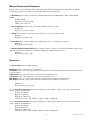
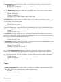
WEB CONTROL PRODUCTS
User Manual
RSTC1000 HMI/PLC Design Guide
FORM NO. L-21208-C-0908
DANGER
Read this manual carefully before installation and operation.
Follow Nexen’s instructions and integrate this unit into your system with care.
This unit should be installed, operated and maintained by qualified personnel ONLY.
Improper installation can damage your system or cause injury or death.
Comply with all applicable codes.
In accordance with Nexen’s established policy of constant product improvement, the specifications contained in this
manual are subject to change without notice. Technical data listed in this manual are based on the latest information
available at the time of printing and are also subject to change without notice.
Technical Support:
800-843-7445
651-484-5900
www.nexengroup.com
Nexen Group, Inc.
560 Oak Grove Parkway
Vadnais Heights, MN 55127
ISO 9001 Certified
FORM NO. L-21208-C-0908
i
Copyright 2008 Nexen Group, Inc.
TABLE OF CONTENTS
Modbus RS485 Communications-------------------------------------------------------------------------------------------------------------1
Connection Diagrams ------------------------------------------------------------------------------------------------------------------------------2
RSTC1000 Modbus Table of Registers -----------------------------------------------------------------------------------------------------3
RSTC1000 Modbus Registers -----------------------------------------------------------------------------------------------------------------4
Product Information ---------------------------------------------------------------------------------------------------------------------4
Modbus Communication Parameters --------------------------------------------------------------------------------------------5
Diagnostics --------------------------------------------------------------------------------------------------------------------------------5
Tuning ----------------------------------------------------------------------------------------------------------------------------------------6
Setup-----------------------------------------------------------------------------------------------------------------------------------------8
Display ---------------------------------------------------------------------------------------------------------------------------------------9
Control---------------------------------------------------------------------------------------------------------------------------------------9
Signal Selection------------------------------------------------------------------------------------------------------------------------10
Diameter Calibration------------------------------------------------------------------------------------------------------------------10
Tension Calibration--------------------------------------------------------------------------------------------------------------------11
Warranty --------------------------------------------------------------------------------------------------------------------------------------------- 14
FORM NO. L-21208-C-0908
ii
MODBUS RS485 COMMUNICATIONS
NOTE: This manual assumes familiarity with the Modbus RTU over Serial Line protocol. If you are not
familiar with this protocol, then the following documents must be read: Modbus Application Protocol
Specification and Modbus over Serial Line Specification & Implementation Guide found at http://www.
modbus.org.
Modbus RTU is a master/slave protocol that allows the RSTC1000 to send information only after it has been requested from the master device, typically the RSTC Operator Panel (ROP), Programmable Logic Controller (PLC),
or Human Machine Interface (HMI). There can be up to 247 devices on one network all communicating with just one
master. Each device on the network must share the same communication settings and have a unique address in the
range of 1 to 247 with the exception of the master, which does not require an address.
The RSTC1000 Modbus RTU communication settings are as follows:
Settings
Network Address Range
Baud Rates
Parity
Stop Bits
Options
1 to 247
4800, 9600, 14400, 19200, 38400, 56000
none, odd, even
1 (odd or even parity), 2 (no parity)
Default
24
19200
None
2
These settings can be changed via the RSTC Communications Software, or must first be used by the master to establish communication with the RSTC1000 and then changed as desired. The ROP has been programmed with the
same communication parameters and will, upon connecting to the RSTC1000, be able to communicate without any
changes. Because the ROP is a master device there can be no other masters on the same Modbus network.
Any address in the range of 1 to 247 can be assigned to the RSTC1000.
Baud rates, which designate the message transmission speed in units of bits per second, can be set for 4800,
9600, 14400, 19200, 38400, or 56000. The larger the baud rate the less time it takes for a message to travel
across the network and the less time a device spends sending or receiving the message. However, the trade off is
typically reduced communication cable length. The Modbus standard specifies the maximum communication cable
length as 1000 meters using a 4-wire implementation (500 meters for a 2-wire implementation), 26 AWG or larger
wire, shielded, at 9600 baud. Cable capacitance and wire resistance affect baud rates, and as cable lengths increase so does the capacitance and resistance. This can cause a reduction in the speed that a message can travel
across the network.
Each message byte that is sent using the Modbus RTU protocol is eleven bits long with the message data byte being
eight bits and then encapsulated by three other bits: start, parity, and stop. The start bit marks the beginning of the
message byte. Parity is used for error detection and is often not necessary as another error detection method, Cyclical Redundancy Checking (CRC), is also performed on the message byte to check for errors. The stop bit marks the
end of the message byte.
Parity can be set for none, odd, or even.
Stop Bits must be set to 1 for use with odd or even parity or 2 for use with no parity.
Load Termination Resistors (LTR) are necessary to reduce noise and are applied to the devices at the remote ends of
the network. These resistors can be installed at the RSTC1000’s Modbus RS485 port connector (refer to Figure 1).
Typical values for LTRs are 150 ohms and 0.5 watts.
1
FORM NO. L-21208-C-0908
CONNECTION DIAGRAMS
Modbus RS485 Port: This port is for communicating
with the RSTC1000 using the Modbus RTU protocol
over a 2-wire or 4-wire RS485 physical layer (Refer to
Figure 1).
ROP - RSTC
Communication Indicator: Yellow indicator, visible
through top cover, will illuminate whenever the
RSTC1000 communicates over the RS485 port.
Communication Error Indicator: Red indicator,
visible through top cover, will illuminate whenever the
RSTC1000 detects an error with a received message.
RSTC1000
Communication Error
Indicator
RSTC
Red
1
+24 VDC
Black
2
DC Common
White (RxB+)
3
TxB+
Yellow (RxA–)
4
TxA–
Blue (TxB+)
5
RxB+
Orange (TxA–)
6
RxA–
Cable Recommendation:
- Shielded
- 24 awg is always sufficient
- 4 wire system, 1000 m (9600 baud)
- 2 wire system, 500 m (9600 baud)
Termination resistors added externally
- Recommend 150 Ω, 0.5 W
LTR = User supplied line termination resistor
Power Indicator
Reset
Communication Indicator
ROP
USB
RS485
Figure 2
Two Wire RS485 Connections
RSTC1000
RSTC1000
PLC or HMI
1
DC Common
2
DC Common
Non-Inverted Tx/Rx
3
TxB+
4
TxA–
5
RxB+
6
RxA–
LTR
Inverted Tx / Rx
Four Wire RS485 Connections
RSTC1000
PLC or HMI
1
DC Common
RxB+
2
DC Common
3
TxB+
4
TxA–
5
RxB+
6
RxA–
LTR
RxA–
TxB+
LTR
TxA–
Figure 1
FORM NO. L-21208-C-0908
2
Modbus RS485 Connections
RSTC1000 MODBUS TABLE OF REGISTERS
Register Name
Type
Page
Register Name
Product Information
Type
Page
Setup
1-4
Product Name
Read Only
4
63
Torque Actuator
Read/Write
8
6-7
Product Number
Read Only
4
64
Torque Actuator Inertia
Read/Write
8
8-9
Serial Number
Read Only
4
65
Tension Zone Selection
Read/Write
8
10-11
Software Part Number
Read Only
4
66
Minimum Output
Read/Write
8
12
Software Revision
Read Only
4
67
Maximum Output
Read/Write
8
68
Standby Output
Read/Write
8
Modbus Comm Setup
15
Baud Rate
Read/Write
5
69
Web Material Selection
Read/Write
8
16
Modbus Device Address
Read/Write
5
70
Average Web Width
Read/Write
9
17
Parity
Read/Write
5
71
Maximum Roll Diameter
Read/Write
9
18
Stop Bits
Read/Write
5
72
Minimum Core Roll Diameter
Read/Write
9
19
Remote Communications Reset
Write Only
5
Diagnostics
Display
78
Display Units
Read/Write
9
79
Language
Read/Write
9
30
Alarm Status
Read Only
5
31-32
Load Cell 1 Tension
Read Only
5
33-34
Load Cell 2 Tension
Read Only
5
80
Panel Write Enable
Read/Write
9
35
Control Output
Read Only
6
81
Manual/Automatic Mode
Read/Write
9
36-37
Roll Diameter
Read Only
6
82
Manual Output Level
Read/Write
9
38
Run/Stop
Read/Write
6
83
Alarm Acknowledge
Write Only
10
39
Splice A
Read/Write
6
84
Output On/Off
Read/Write
10
40
Splice B
Read/Write
6
41
Adaptation
Read Only
6
Read/Write
10
43-44
Taper Tension Setpoint
Read Only
6
Tuning
Control
Signal Selection
85
Run/Stop Signal
Diameter Sensor Calibration
87
Diameter Sensor Installed
Write Only
10
45
Taper Tension Enable
Read/Write
6
88
Diameter-Core Size
Read/Write
10
46-47
Tension Setpoint
Read/Write
7
89
Diameter-Large Roll Size
Read/Write
10
48
Taper
Read/Write
7
90
Diameter Measure Flag
Read/Write
11
49-50
Taper Delay
Read/Write
7
51
Gain
Read/Write
7
73-74
Minimum Tension Setpoint
Read/Write
11
52
Stabilization
Read/Write
7
75-76
Maximum Tension Setpoint
Read/Write
11
53
Initial Adaptation
Read/Write
7
77
Tension Calibration Set
Read/Write
11
54
Splice Adaptation
Read/Write
7
93
Load Cell Measure Flag
Read/Write
12
55
Adaptation Rate
Read/Write
7
94-95
Tare Tension-Calibration Set 1
Read/Write
12
56
Remote Tension Setpoint Enable Read/Write
7
96-97
Span Tension-Calibration Set 1
Read/Write
12
98-99
Tare Tension-Calibration Set 2
Read/Write
12
Setup
Tension Calibration
60
Tension Monitor Enable
Read/Write
8
100-101
Span Tension-Calibration Set 2
Read/Write
12
61
Tension Alarm Tolerance
Read/Write
8
102-103
Tare Tension-Calibration Set 3
Read/Write
13
62
Alarm Output Type
Read/Write
8
104-105
Span Tension-Calibration Set 3
Read/Write
13
3
FORM NO. L-21208-C-0908
RSTC1000 MODBUS REGISTERS
All values written to or read from the RSTC1000 must be in Imperial units. Conversion of values from other units of
measure are done within the HMI or PLC.
The following Modbus registers are numbered per the Modbus standard. Many PLCs use an alternate numbering
scheme and the Modbus register numbers can be converted to the PLC numbering scheme by adding 40,001 to each
Modbus register number.
Common Definitions and Abbreviations:
lsb:
least significant byte
msb:
most significant byte
lsw:
least significant word
msw: most significant word
byte:
8 bits, 0-255 range
word: 2 bytes, 0-65535 range
PRODUCT INFORMATION
1 – 4: Product Name Sent as ASCII values, read only.
Example: RSTC1000
Register 1: R (msb), S (lsb)
Register 2: T (msb), C (lsb)
Register 3: 1 (msb), 0 (lsb)
Register 4: 0 (msb), 0 (lsb)
6 – 7: Product Number Sent as long integer, read only.
Example: 964523
Register 6: 14 (msw)
Register 7: 47019 (lsw)
964523 = (14 * 65536) + 47019
8 – 9: Serial Number Sent as long integer, read only.
Example: 1234567
Register 8: 18 (msw)
Register 9: 54919 (lsw)
1234567 = (18 * 65536) + 54919
10 – 11: Software Part Number Sent as long integer, read only.
Example: 12345
Register 10: 0 (msw)
Register 11: 12345 (lsw)
12345 = (0 * 65536) + 12345
12: Software Revision Sent as ASCII value, read only.
Example: A
Register 12: 0 (msb), 65 (lsb)
4
FORM NO. L-21208-C-0908
MODBUS COMMUNICATION PARAMETERS
Writing to registers 15-18 changes the communication parameters. New paramter values take effect immediately
after writing to register 19, or after turning the RSTC1000 power off and back on.
15: Baud Rate Sent as integer, read & write. Supported baud rates are 4800, 9600, 14400, 19200, 38400,
56000).
Example: 19200
Register 15: 75 (msb), 0 (lsb)
19200 = (75 * 256) + 0
16: Device Address Sent as integer, read & write. Address values are 1–247.
Example: 24
Register 16: 0 (msb), 24 (lsb)
17: Parity Sent as integer, read & write. Parity values are 1 = even, 2 = odd, 3 = none.
Example: 3
Register 17: 0 (msb), 3 (lsb)
18: Stop Bits Sent as integer, read & write. Stop Bit values are 1 = 1 stop bit, 2 = 2 stop bits.
Example: 2
Register 18: 0 (msb), 2 (lsb)
19: Remote Communications Reset Sent as integer, write only. Writing a 1 will cause RSTC1000 to begin using
updated communication parameters immediately. Reading this variable will return a zero.
Example: 1
Register 19: 0 (msb), 1 (lsb)
DIAGNOSTICS
30: Alarm Status Sent as integer, read only.
Web Break: value = 128, total loss of web tension.
No Control: value = 72, control signal output has reached 0% or 100% during automatic operation and web tension
is not at set point.
High Tension: value = 64, web tension is greater than the high-tension limit.
Low Tension: value = 32, web tension is less than the low-tension limit.
Max Output: value = 16, control signal output has reached maximum output limit, typically 100%.
Min Output: value = 8, control signal output has reached minimum output limit, typically 0%.
Example: 32
Register 30: 0 (msb), 32 (lsb)
31 - 32: Load Cell 1 Tension Floating point number sent as long integer * 1000 in units of lbs, read only, tension
range is 0.000 to 10,000.000 lbs.
Example: 543.812 lbs
Register 31: 8 (msw)
Register 32: 19524 (lsw)
Load Cell 1 Tension = ((8 * 65536) + 19524) / 1000 = 543.812 lbs
33 - 34: Load Cell 2 Tension Floating point number sent as long integer * 1000 in units of lbs, read only, tension
range is 0.000 to 10,000.000 lbs.
Example: 543.000 lbs
Register 33: 8 (msw)
Register 34: 18712 (lsw)
Load Cell 2 Tension = ((8 * 65536) + 18712) / 1000 = 543.000 lbs
5
FORM NO. L-21208-C-0908
35: Control Output % Floating point sent as integer * 10, read only. Control Output % range is 0.0 to 100.0.
Example: 45.6%
Register 35: 1 (msb), 200 (lsb)
Control Output = ((1 * 256) + 200) / 10) = 45.6%
36 – 37: Roll Diameter Floating point number sent as long integer * 1000 in units of inches, read only, diameter
range is 0.000 to 400.000.
Example: 34.835 inches
Register 36: 0 (msw)
Register 37: 34835 (lsw)
Roll Diameter = ((0 * 65536) + 34835) / 1000 = 34.835 inches
38: Run/Stop Sent as integer, read & write. Run/Stop values are 1 = run and 0 = stop. Writing a 1 to the
RSTC1000 will place it in the run mode and writing a 0 will place it in the stop mode. Reading this register provides
the RSTC1000’s current operating mode.
Example: 1
Register 38: 0 (msb), 1 (lsb)
39: Splice A Sent as integer, read & write. Write 1 to make Control Output A the controlling output and Control
Output B the standby output. Register 39 can be read immediately after initially writing 1 and the returned value will
be 1 for approximately one second before returning to zero.
Example: 1
Register 39: 0 (msb), 1 (lsb)
40: Splice B Sent as integer, read & write. Write 1 to make Control Output B the controlling output and Control
Output A the standby output. Register 40 can be read immediately after initially writing 1 and the returned value will
be 1 for approximately one second before returning to zero.
Example: 1
Register 40: 0 (msb), 1 (lsb)
41: Adaptation Floating point number sent as integer * 10, read only. Read the current calculated adaptation value.
Used for diagnostic work. Adaptation ranges from 0.0 to 100.0.
Example: 8.9
Register 41: 0 (msb), 89 (lsb)
Adaptation = ((0 * 256) + 89) / 10 = 8.9
43 – 44: Taper Tension Setpoint Floating point number sent as long integer * 1000 in units of lbs, read only,
range is 0.000 to 10,000.000 lbs but restricted by Maximum and Minimum Tension Setpoint values. Reads the
calculated taper tension setpoint which decreases as roll diameter increases, calculation is always performed regardless of Taper Tension Enable. Taper Tension Setpoint is a function of Taper Factor and a condition of Taper Delay.
Example: 543.812 lbs
Register 43: 8 (msw)
Register 44: 19524 (lsw)
Taper Tension Setpoint = ((8 * 65536) + 19524) / 1000 = 543.812 lbs
TUNING
45: Taper Tension Enable Sent as integer, read & write. Taper Tension Enable has values of 0 for off and 1 for on.
When set to 1, web tension will decrease with increasing roll diameter as a function of Taper Factor and a condition
of Taper Delay, when set to 0, web tension remains at Tension Setpoint value.
Example: 1
Register 45: 0 (msb), 1 (lsb)
FORM NO. L-21208-C-0908
6
46 – 47: Tension Setpoint Floating point number sent as long integer * 1000 in units of lbs, read & write, range is
0.000 to 10,000.000 lbs but restricted by Maximum and Minimum Tension Setpoint values. Read the current tension
setpoint or write a new tension setpoint value.
Example: 543.812 lbs
Register 46: 8 (msw)
Register 47: 19524 (lsw)
Tension Setpoint = ((8 * 65536) + 19524) / 1000 = 543.812 lbs
48: Taper Sent as integer, read & write. Taper Factor has a range of 0 to 100. Taper Factor controls how much the
tension setpoint is decreased for an increase in roll diameter. Larger values of Taper Factor will increase the rate of decrease and smaller values will decrease the rate of decrease. A value of 0 will result in no tension setpoint decrease.
Example: 37
Register 48: 0 (msb), 37 (lsb)
49 - 50: Taper Delay Floating point number sent as long integer * 1000 in units of inches, read & write, range of
0.000 to 100.000. This value specifies the roll diameter at which tension tapering is to begin.
Example: 34.835 inches
Register 49: 0 (msw)
Register 50: 34835 (lsw)
Taper Delay = ((0 * 65536) + 34835) / 1000 = 34.835 inches
51: Gain Floating point number sent as integer * 10, read & write. Gain has a range of 0.0–10.0.
Example: 8.9
Register 51: 0 (msb), 89 (lsb)
Gain = ((0 * 256) + 89) / 10 = 8.9
52: Stabilization Floating point number sent as integer * 10, read & write. Stabilization has a range of 1.0–50.0.
Example: 5.3
Register 52: 0 (msb), 53 (lsb)
Stabilization = ((0 * 256) + 53) / 10 = 5.3
53: Initial Adaptation Floating point number sent as integer * 10, read & write. Initial Adaptation has a range of
1.0–20.0.
Example: 11.4
Register 53: 0 (msb), 114 (lsb)
Initial Adaptation = ((0 * 256) + 114) / 10 = 11.4
54: Splice Adaptation Floating point number sent as integer * 10, read & write. Splice Adaptation has a range of
1.0–20.0.
Example: 11.4
Register 54: 0 (msb), 114 (lsb)
Splice Adaptation = ((0 * 256) + 114) / 10 = 11.4
55: Adaptation Rate Floating point number sent as integer * 10, read & write. Adaptation Rate has a range of
2.0–20.0.
Example: 11.4
Register 55: 0 (msb), 114 (lsb)
Adaptation Rate = ((0 * 256) + 114) / 10 = 11.4
56: Remote Tension Setpoint Enable Sent as integer, read & write. Remote Tension Setpoint Enable has values
of 0 for Off and 1 for On. Set to 1 for the Tension Setpoint value to be read from the Remote Tension Setpoint analog
input. Set to 0 for the Tension Setpoint value to be sent over the Modbus network.
Example: 1
Register 60: 0 (msb), 1 (lsb)
7
FORM NO. L-21208-C-0908
SETUP
60: Tension Monitor Enable Sent as integer, read & write. Tension Output Enable has values of 0 for Off and 1 for
On. Set to 1 for actual tension to be available on Control Output B. Set to 0 for the controlling or standby outputs to
be available on Control Output B. Splice B register command and hardware input is ignored when Tension Output Enable is set to 1.
Example: 1
Register 56: 0 (msb), 1 (lsb)
61: Tension Alarm Tolerance Sent as integer, read & write. Tension Alarm Tolerance has a range of 0–100%.
Example: 25%
Register 61: 0 (msb), 25 (lsb)
Tension Alarm Tolerance = (0 * 256) + 25 = 25%
62: Alarm Output Type Sent as integer, read & write. Alarm Output Type has values of 0 for Normally Open and 1 for
Normally Closed.
Example: 1
Register 62: 0 (msb), 1 (lsb)
63: Torque Actuator Sent as integer, read & write.
Torque Actuator has the following values:
1 – Pneumatic Brake
2 – Pneumatic Clutch
3 – Magnetic Particle Brake
4 – Magnetic Particle Clutch
5 – Electric Brake
6 – Electric Clutch
7 – Motor-Drive System
Example 2 – Pneumatic Clutch
Register 63: 0 (msb), 2 (lsb)
64: Torque Actuator Inertia Sent as integer * 100 in units of lb-ft2, read & write. Torque Actuator Inertia has a range
of 0.00 to 100.00
Example 21.37 lb-ft2
Register 64: 8 (msb), 89 (lsb)
Torque Actuator Inertia = ((8 * 256) + 89) / 100 = 21.37 lb-ft2
65: Tension Zone Selection Sent as integer, read & write. Tension Zone Selection has values of 1 for Unwind and 2
for Wind.
Example 2 – Pneumatic Clutch
Register 65: 0 (msb), 2 (lsb)
66: Minimum Output % Sent as intger, read & write. Minimum Output has a range of 0–100 %.
Example 32%
Register 66: 0 (msb), 32 (lsb)
67: Maximum Output % Sent as intger, read & write. Maximum Output has a range of 0–100 %.
Example 10%
Register 67: 0 (msb), 10 (lsb)
68: Standby Output % Sent as intger, read & write. Standby Output has a range of 0–100 %.
Example 67%
Register 68: 0 (msb), 67 (lsb)
69: Web Material Selection Sent as integer, read & write. Web Material Selection has values of 1 for paper and
plastic, 2 for aluminum, and 3 for steel.
Example 2 – aluminum
Register 69: 0 (msb), 2 (lsb)
FORM NO. L-21208-C-0908
8
70: Average Web Width Floating point number sent as integer * 10 in units of inches, read & write. Average Web
Width has a range of 1.0–400.0 inches.
Example 287.2 inches
Register 70: 11 (msb), 56 (lsb)
Average Web Width = ((11 * 256) + 56) / 10 = 287.2 inches
71: Maximum Roll Diameter Floating point number sent as integer * 10 in units of inches, read & write. Large Roll
Diameter has a range of 0.0–400.0 inches.
Example 40.5 inches
Register 71: 1 (msb), 149 (lsb)
Average Web Width = ((1 * 256) + 149) / 10 = 40.5 inches
72: Minimum Core Roll Diameter Floating point number sent as integer * 10 in units of inches, read & write. Core
Roll Diameter has a range of 0.0–50.0 inches.
Example 3.5 inches
Register 71: 0 (msb), 35 (lsb)
Average Web Width = ((0 * 256) + 35) / 10 = 3.5 inches
DISPLAY
78: Display Units Sent as integer, read & write. Display Units has values of 0 for Imperial (English) and 1 for Metric.
Display Units has no effect on the RSTC as it only stores the value, and register values are communicated in Imperial
units only. Any Imperial to Metric or Metric to Imperial conversion is done in the HMI or PLC.
Example 1 – Metric
Register 77: 0 (msb), 1 (lsb)
79: Language Sent as integer, read & write. Language has values of 0 for English, 1 for Spanish, 2 for French, 3 for
German, and 4 for Italian. Language is used primarily to select the language in which the RSTC Operator Panel displays text and has no effect on the RSTC.
Example 0 – English
Register 78: 0 (msb), 0 (lsb)
CONTROL
80: Panel Write Enable Sent as integer, read & write. Panel Write Enable has values of 0 for disable and 1 for
enable. RSTC1000 sets this register to 0 whenever the RSTC Communications Software is connected to the
RSTC1000. An HMI can read this register and when equal to 0, any values sent by the HMI will be ignored by the
RSTC1000. After the RSTC Communications Software is disconnected, the RSTC1000 sets this register to 1 and
the HMI can again send values to the RSTC1000. This handshaking can be used to prevent two devices from sending
register value changes to the RSTC1000 at the same time.
Example 1 – Enable
Register 79: 0 (msb), 1 (lsb)
81: Manual/Automatic Mode Sent as integer, read & write. Manual/Automatic Mode has a value of 0 for Manual
and 1 for Automatic. When mode is set to Manual the RSTC1000 control output can be controlled using the Manual
Output Level register. When mode is set to Automatic the RSTC1000 control output is automatically controlled and
writing to Manual Output Level has no effect.
Example 1 – Automatic
Register 81: 0 (msb), 1 (lsb)
82: Manual Output Level % Sent as integer, read & write. Manual Output Level has a range of 0 to 100%. When
the RSTC1000 is in manual mode, writing to this register will immediately change the Control Output’s signal level.
Example 67%
Register 82: 0 (msb), 67 (lsb)
9
FORM NO. L-21208-C-0908
83: Alarm Acknowledge Sent as integer, write only. Alarm Acknowledge has a value of 1 to acknowledge an alarm.
Writing a 1 to this register will turn off all alarm outputs until the alarm condition is satisfied and occurs again.
Example 1
Register 83: 0 (msb), 1 (lsb)
84: Output On/Off Sent as integer, read & write. Output On/Off has a value of 0 for Off and 1 for On. Writing to
this register will affect both RSTC1000 control outputs.
Example 0 – Output Off
Register 84: 0 (msb), 0 (lsb)
SIGNAL SELECTION
85: Run/Stop Signal Selection Sent as integer, read & write. Run/Stop Signal Selection has the following values:
1 – run/stop maintained
2 – run/stop momentary
3 – run only momentary
4 – run pulsed (encoder)
5 – run/stop signal via Modbus Communications
Example 4 – run pulsed (encoder)
Register 85: 0 (msb), 4 (lsb)
DIAMETER CALIBRATION
When calibrating the roll diameter signal, send registers 87 through 90 in the order shown here.
87: Diameter Sensor Installed Sent as integer, write only. Diameter Sensor Installed has a value of 0 for no sensor
installed and 1 for sensor installed. When Diameter Sensor Installed is set to 0, values for registers 89 and 90 are
ignored and Roll Diameter register is always 0.
Example 1
Register 87: 0 (msb), 1 (lsb)
88: Diameter – Core Size Floating point value sent as integer *10 in units of inches, read & write. Core Size is the
outside diameter of roll’s core or any roll diameter that is smaller than the roll diameter used for Large Roll Size. It has
a range of 0.0 to 50.0 inches
Example 3.5 inches
Register 88: 0 (msb), 35 (lsb)
Core Size = ((0 * 256) + 35) / 10 = 3.5 inches
89: Diameter – Large Roll Size Floating point value sent as integer *10 in units of inches, read & write. Large Roll
Size is the outside diameter of any roll used for diameter calibration that is larger than the diameter used for Core Size.
It has a range of 0.0 to 400.0 inches
Example 42.7 inches
Register 89: 1 (msb), 171(lsb)
Large Roll Size = ((1 * 256) + 171) / 10 = 42.7 inches
FORM NO. L-21208-C-0908
10
90: Diameter Measure Flag Sent as integer, read & write. Diameter Measure Flag is only to be used after registers
87, 88, and 89 have been written.
1. Apply the voltage representing the Core Size to the Diameter Sensor Input terminal and then write a 1 to
Diameter Measure Flag register. RSTC1000 will measure this voltage and calibrate the smaller roll size.
2. Read Diameter Measure Flag to determine when previous calibration step is complete. Calibration step is
complete when flag = 0.
3. Apply the voltage representing the Large Roll Size to the Diameter Sensor Input terminal and then write a 2 to
Diameter Measure Flag register. RSTC1000 will measure this voltage and calibrate the larger roll size.
4. Read Diameter Measure Flag to determine when previous calibration step is complete. Calibration step is
complete when flag = 0.
The diameter measurement is now calibrated and ready for use.
TENSION CALIBRATION
Set the Maximum Tension Setpoint before calibrating the tension sensors. Afterwards, re-calibration of tension sensors
is necessary whenever Maximum Tension Setpoint is changed.
73 – 74: Minimum Tension Setpoint Floating point number sent as long integer * 1000 in units of lbs, read & write,
range is 0.000 to 10,000.000 lbs. Minimum Tension Setpoint value must be less than Maximum Tension Setpoint
value. Read the current minimum tension setpoint or write a new minimum tension setpoint value.
Example: 55.742 lbs
Register 73: 0 (msw)
Register 74: 55742 (lsw)
Tension Setpoint = ((0 * 65536) + 55742) / 1000 = 55.742 lbs
75 – 76: Maximum Tension Setpoint Floating point number sent as long integer * 1000 in units of lbs, read & write,
range is 0.000 to 10,000.000 lbs. Maximum Tension Setpoint value must be greater than Minimum Tension Setpoint
value. Read the current maximum tension setpoint or write a new maximum tension setpoint value.
Example: 324.742 lbs
Register 75: 4 (msw)
Register 76: 62598 (lsw)
Tension Setpoint = ((4 * 65536) + 62598) / 1000 = 324.742 lbs
77: Tension Calibration Set Sent as integer, read & write. Tension Calibration Set has values of 1 for Calibration
Set 1, 2 for Calibration Set 2, and 3 for Calibration Set 3. Writing a value to this register selects the desired calibration set.
Example 3 – Tension Calibration Set 3
Register 80: 0 (msb), 3 (lsb)
11
FORM NO. L-21208-C-0908
When calibrating the tension sensor signal, the registers for each calibration set must be written in the order shown
here.
Calibration Set 1
94 – 95: Tare Tension Floating point number sent as long integer * 1000 in units of lbs, read & write. Tare Tension is
typically set to 0 and represents the web tension at the tare condition when the load cells measure only the weight of
the tension sensing roller and its associated hardware.
Example: 324.742 lbs
Register 94: 4 (msw)
Register 95: 62598 (lsw)
Tare Tension = ((4 * 65536) + 62598) / 1000 = 324.742 lbs
96 – 97: Span Tension Floating point number sent as long integer * 1000 in units of lbs, read & write. Span Tension
has a range of 1 to 10,000 lbs and represents the load seen by the load cells when a known web tension is applied
that is less than the Maximum Tension Setpoint.
Example: 350.000 lbs
Register 96: 5 (msw)
Register 97: 22320 (lsw)
Span Tension = ((5 * 65536) + 22320) / 1000 = 350.000 lbs
93: Load Cell Measure Flag Sent as integer, read & write. Load Cell Measure Flag is only used after Tare Tension
and Span Tension registers have been written.
1. Remove any web tension from the tension sensing roller and then write a 1 to Load Cell Measure Flag. This
calibrates the load cell tare condition.
2. Read Load Cell Measure Flag to determine when previous calibration step is complete. Under normal conditions, the tare calibration takes 10 seconds. Calibration step is complete when flag = 0.
3. Apply the web tension load that was sent to Span Tension register and then write a 2 to Load Cell Measure
Flag. This calibrates the load cell span condition.
4. Read Load Cell Measure Flag to determine when previous calibration step is complete. Under normal conditions, the span calibration takes 6 seconds. Calibration step is complete when flag = 0.
5. Remove any web tension from the tension sensing roller and write a 3 to Load Cell Measure Flag. This checks
the load cell tare condition.
6. Read Load Cell Measure Flag to determine when previous calibration step is complete. Under normal conditions, the tare check takes 2 seconds. Calibration step is complete when flag = 0.
Load Cell Calibration Set 1 is now calibrated.
Calibration Set 2
98 – 99: Tare Tension Floating point number sent as long integer * 1000 in units of lbs, read & write. Tare Tension is
typically set to 0 and represents the web tension at the tare condition when the load cells measure only the weight of
the tension sensing roller and its associated hardware.
100 – 101: Span Tension Floating point number sent as long integer * 1000 in units of lbs, read & write. Span
Tension has a range of 1 to 10,000 lbs and represents the load seen by the load cells when a known web tension is
applied that is less than the Maximum Tension Setpoint.
93: Load Cell Measure Flag Sent as integer, read & write. Load Cell Measure Flag is only used after Tare Tension
and Span Tension registers have been written.
1. Remove any web tension from the tension sensing roller and then write a 4 to Load Cell Measure Flag. This
calibrates the load cell tare condition.
2. Read Load Cell Measure Flag to determine when previous calibration step is complete. Under normal conditions, the tare calibration takes 10 seconds. Calibration step is complete when flag = 0.
3. Apply the web tension load that was sent to Span Tension register and then write a 5 to Load Cell Measure
Flag. This calibrates the load cell span condition.
FORM NO. L-21208-C-0908
12
4. Read Load Cell Measure Flag to determine when previous calibration step is complete. Under normal conditions, the span calibration takes 6 seconds. Calibration step is complete when flag = 0.
5. Remove any web tension from the tension sensing roller and write a 6 to Load Cell Measure Flag. This checks
the load cell tare condition.
6. Read Load Cell Measure Flag to determine when previous calibration step is complete. Under normal conditions, the tare check takes 2 seconds. Calibration step is complete when flag = 0.
Load Cell Calibration Set 2 is now calibrated.
Calibration Set 3
102 – 103: Tare Tension Floating point number sent as long integer * 1000 in units of lbs, read & write. Tare Tension
is typically set to 0 and represents the web tension at the tare condition when the load cells measure only the weight
of the tension sensing roller and its associated hardware.
104 – 105: Span Tension Floating point number sent as long integer * 1000 in units of lbs, read & write. Span
Tension has a range of 1 to 10,000 lbs and represents the load seen by the load cells when a known web tension is
applied that is less than the Maximum Tension Setpoint.
93: Load Cell Measure Flag Sent as integer, read & write. Load Cell Measure Flag is only used after Tare Tension
and Span Tension registers have been written.
1. Remove any web tension from the tension sensing roller and then write a 7 to Load Cell Measure Flag. This
calibrates the load cell tare condition.
2. Read Load Cell Measure Flag to determine when previous calibration step is complete. Under normal conditions, the tare calibration takes 10 seconds. Calibration step is complete when flag = 0.
3. Apply the web tension load that was sent to Span Tension register and then write a 8 to Load Cell Measure
Flag. This calibrates the load cell span condition.
4. Read Load Cell Measure Flag to determine when previous calibration step is complete. Under normal conditions, the span calibration takes 6 seconds. Calibration step is complete when flag = 0.
5. Remove any web tension from the tension sensing roller and write a 9 to Load Cell Measure Flag. This checks
the load cell tare condition.
6. Read Load Cell Measure Flag to determine when previous calibration step is complete. Under normal conditions, the tare check takes 2 seconds. Calibration step is complete when flag = 0.
Load Cell Calibration Set 3 is now calibrated.
13
FORM NO. L-21208-C-0908
WARRANTY
Warranties
Nexen warrants that the Products will be free from any defects in material or workmanship for a period of 12 months
from the date of shipment. NEXEN MAKES NO OTHER WARRANTY, EXPRESS OR IMPLIED, AND ALL IMPLIED
WARRANTIES, INCLUDING WITHOUT LIMITATION, IMPLIED WARRANTIES OF MERCHANTABILITY AND FITNESS FOR A PARTICULAR PURPOSE ARE HEREBY DISCLAIMED. This warranty applies only if (a) the
Product has been installed, used and maintained in accordance with any applicable Nexen installation or maintenance
manual for the Product; (b) the alleged defect is not attributable to normal wear and tear; (c) the Product has not been
altered, misused or used for purposes other than those for which it was intended; and (d) Buyer has given written notice of the alleged defect to Nexen, and delivered the allegedly defective Product to Nexen, within one year of the date
of shipment.
Exclusive Remedy
The exclusive remedy of the Buyer for any breach of the warranties set out above will be, at the sole discretion of Nexen, a repair or replacement with new, serviceably used or reconditioned Product, or issuance of credit in the amount of
the purchase price paid to Nexen by the Buyer for the Products.
Limitation of Nexen’s Liability
TO THE EXTENT PERMITTED BY LAW NEXEN SHALL HAVE NO LIABILITY TO BUYER OR ANY OTHER PERSON FOR INCIDENTAL DAMAGES, SPECIAL DAMAGES, CONSEQUENTIAL DAMAGES OR OTHER DAMAGES OF ANY KIND OR NATURE WHATSOEVER, WHETHER ARISING OUT OF BREACH OF WARRANTY OR
OTHER
BREACH OF CONTRACT, NEGLIGENCE OR OTHER TORT, OR OTHERWISE, EVEN IF NEXEN SHALL HAVE
BEEN ADVISED OF THE POSSIBILITY OR LIKELIHOOD OF SUCH POTENTIAL LOSS OR DAMAGE. For all of
the purposes hereof, the term “consequential damages” shall include lost profits, penalties, delay images, liquidated
damages or other damages and liabilities which Buyer shall be obligated to pay or which Buyer may incur based
upon, related to or arising out of its contracts with its customers or other third parties. In no event shall Nexen be liable for any amount of damages in excess of amounts paid by Buyer for Products or services as to which a breach of
contract has been determined to exist. The parties expressly agree that the price for the Products and the services was
determined in consideration of the limitation on damages set forth herein and such limitation has been specifically bargained for and constitutes an agreed allocation of risk which shall survive the determination of any court of competent
jurisdiction that any remedy herein fails of its essential purpose.
Limitation of Damages
In no event shall Nexen be liable for any consequential, indirect, incidental, or special damages of any nature whatsoever, including without limitation, lost profits arising from the sale or use of the Products.
Warranty Claim Procedures
To make a claim under this warranty, the claimant must give written notice of the alleged defect to whom the Product
was purchased from and deliver the Product to same within one year of the date on which the alleged defect first
became apparent.
Nexen Group, Inc.
560 Oak Grove Parkway
Vadnais Heights, MN 55127
800.843.7445
Fax: 651.286.1099
www.nexengroup.com
ISO 9001 Certified
FORM NO. L-21208-C-0908
14