1
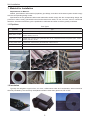
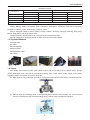
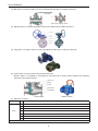
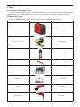
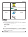
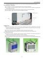
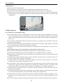
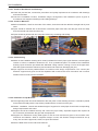
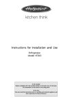
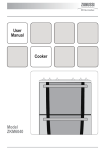
Change for life
Modular Air-cooled Scroll Chiller
Unit Installation
GREE ELECTRIC APPLIANCES, INC.OF ZHUHAI
CONTENTS
Installation Guides.........................................................................................1
1. Material for Installation..............................................................................2
1.1 Pipelines.................................................................................................................... 2
1.2 Insulation................................................................................................................... 2
1.3 Sectional Material...................................................................................................... 3
1.4 Valves........................................................................................................................ 3
1.5 Filters for the Water System...................................................................................... 5
1.6 Water Softeners......................................................................................................... 5
2. Tools............................................................................................................6
2.1 Cutting and Finishing Tools........................................................................................ 6
2.2 Measuring Tools......................................................................................................... 6
3. Installation .................................................................................................7
3.1 Preparations.............................................................................................................. 7
3.2 Space for Installation and Maintenance..................................................................... 8
3.3 Installation Foundation............................................................................................... 9
3.4 Main Unit.................................................................................................................... 9
3.5 Water System.......................................................................................................... 10
3.6 Installation of the Expansion Tank........................................................................... 18
3.7 Instalation of Condensate Pipes.............................................................................. 19
3.9 Wiring of Control Lines............................................................................................ 21
3.10 External Wirnig of Control Lines............................................................................ 21
3.11 Wiring among Modules.......................................................................................... 22
3.12 Wiring of the Electric Cabinet (Ref.)...................................................................... 23
3.13 Commissioning...................................................................................................... 23
4. Typical Problems and Impacts................................................................26
Unit Installation
Installation Guides
WARNING:
◆◆ Installation should be performed by GREE appointed servicemen, or improper installation would lead to
unusual operation, water leakage, electric shock or fire hazard.
◆◆ The unit should be installed on the foundation which is capable of supporting the unit, or the unit would
fall off or even lead to personal injury.
◆◆ All electric installation should be done by electrician in accordance with local laws and regulations, as
well as the User’s Manual and this Service Manual. Besides, the special power lines should be used, as
any improper line would lead to electric shock or fire hazard.
◆◆ All electric lines should be safe and secured reliably. Be sure the terminal board and electric lines will not
be affected by any external force, or it would lead to fire hazard.
◆◆ The electric lines between the indoor and outdoor units should run properly to make the cover of the
electric box secured tightly, or it would cause the terminal board overheated or cause electric shock or
fire hazard.
◆◆ Cut off the power supply before touching any electric element.
CAUTION:
◆◆ The unit should be grounded properly and the ground line is not allowed to connect with the gas line,
water line, lightning rod or phone line.
◆◆ The breaker should be installed, or it would lead to electric shock.
◆◆ The drain pipe should be installed in accordance with the User’s Manual and this Service Manual to
ensure free drainage, and the drain pipe should be insulated against condensation. Once the drain pipe
is installed improperly, it would lead to water leak which then will damps the ceiling and furniture.
◆◆ Do not place the unit where there is oil fog, like kitchen, or the plastic would be aged, broken off or the
polluted evaporator would lead to water leak and poor performance.
◆◆ Do not place the unit where there is corrosive gas (like sulfur dioxide), or the corroded copper tubes or
welded joint would lead to refrigerant leakage.
◆◆ Do not place the unit where there is inflammable gas, carbon fiber, inflammable dust or volatile
combustible, as they would lead to fire hazard.
SAFETY:
◆◆ Always use safety outfits at the construction site.
◆◆ No smoking and no drunken operation are allowed at the construction site.
◆◆ Wear no gloves and tighten the cuff when operating the machinery and electrical equipment. Do not
maintain it during operation.
◆◆ Use the abrasive-disk cutter and stand at the side of the rotating abrasive disk.
◆◆ Clean the opening when installing the riser pipe, and then cover it tightly. Do not throw down any material.
◆◆ The use of the electric and gas welders should be approved firstly. Once used, a fire distinguisher should
be prepared and a service man should be there always. There should be no inflammable and explosive
substances around the welding site.
◆◆ A platform should be set up when working high above the ground.
EXECUTIVE STANDARDS:
◆◆ Fire Protection Design of Tall Buildings GB50045-95.
◆◆ Code of Design on Building Fire Protection and Prevention GB50016-2006.
◆◆ Code for Electric Design of Civil Buildings JGJ16-2008.
◆◆ Technical Specification f or Construction of Air Conduct JGJ141-2004.
◆◆ Unified Standard for Constructional Quality Acceptance of Building Engineering GB50300-2001.
◆◆ Code of Acceptance for Construction Quality of Ventilation and Air Conditioning Works GB50243-2002.
◆◆ Code for Acceptance of Construction Quality of Water Supply Drainage and Heating Works GB50242-2002.
◆◆ Code for Construction and Acceptance of Refrigeration and Air Separating Equipment Installation
Engineering GB 50274-2005.
1
Unit Installation
1. Material for Installation
Requirements on Material:
Models, specifications and material of pipelines, pipe fittings, and valves of the water system should comply
with the corresponding design codes.
Specifications of the galvanized carbon steel tubes also should comply with the corresponding design and
production codes: evenly galvanized internal and external tube walls, no rust, no burrs, and no unmatched
thread etc. All tubes should have got the qualification certificates and other necessary quality certificates.
1.1 Pipelines
Tube Types
Application
Water (t > 95℃ ) Tubes
Type
Welded steel, seamless steel, galvanized steel
Water (t≤95℃ ) Tubes
Welded steel, seamless steel, galvanized steel, nodular cast iron, composited aluminum and plastic (PAP1,
XPAP2, RPAP5), PB, PE-X
Water (t≤60℃ ) Tubes
Welded steel, seamless steel, galvanized steel, PP-R, composited aluminum and plastic (PAP1, XPAP2,
RPAP5), PB, PE-X, PE-RT
Cooling Water Tubes
Welded steel, seamless steel, galvanized steel, nodular cast iron
Drain Tubes
Condenation Tubes
PVC,UPVC
Galvanized steel, PE, PVC, UPVC
1.2 Insulation
Typically the refrigerant copper tubes, air ducts, chilled water tubes and condensation tubes should be
thermally insulated by the commonly used plastic insulation rather than glass wool, PE or PEF.
2
Unit Installation
Insulation Thickess
Gas-expanded Rubber
Diameter(mm)
Glass Wool
Zone Ⅰ
Zone Ⅱ
Zone Ⅰ
Zone Ⅱ
DN15-DN25
above 15mm
above 20mm
above 30mm
above 30mm
DN32-DN50
above 25mm
above 30mm
above 35mm
above 35mm
DN65-DN80
above 30mm
above 35mm
above 35mm
above 40mm
DN100
above 35mm
above 40mm
above 40mm
above 45mm
Note: under the tropical climate, the insulation should be thickened or doubled.
Zones in China are classified by the degree of humidity.
Zone I: Beijing, Tianjin, Chongqing, Xi’an, Hangzhou, Zhengzhou, Changsha, Nanchang, Shenyang,
Changchun, Herbing, Jinan, Shijiazhuang, Guiyang, Taipei.
Zone II: Shanghai, Nanjing, Wuhan, Dalian, Fuzhou, Xiamen, Gumming, Chengdu, Nanning, Hong Kong,
Macao, Guangzhou, and other coastal cities.
Thickness listed in the table above all is larger than the required thickness.
Special adhesives for insulation should be used, as shown in the figure below.
1.3 Sectional Material
◆◆ Angle Steel
◆◆ I steel
◆◆ Channel Steel
◆◆ Squire Steel
◆◆ Rectangular Steel
◆◆ H Steel
1.4 Valves
The usually used valves incudes: gate valves, shut-off valves, throttling valves, gauge valves, plunger
valves, diaphragm valve, plug valves, ball valves, butterfly valve, check valves, safety valves, drain valves,
regulating valves, foot valves, and sewer valves etc.
(1). Gate Valve: its nominal diameter generally is or larger than 50mm and is mainly used to cut off the tube flow.
(2). Shut-off Valve and Throttling Valve: its nominal diameter is limited to 200 or below. The shut-off valve is
used to cut off the tube flow and the throttling valve is mainly used to throttle the tube flow.
3
Unit Installation
(3). Ball Valve: it is mainly used to cut off or distribute the tube flow or change its direction.
Float valve
Split ball valve (large caliber)
(4). Batterfly Valve: it is widely applicable to all kinds of fluids under 2.0MPa and 200℃ .
Hand Wheel
Driving
Mechanism
Valve Stem
Butterfly Plate
Valve Body
(5). Plug Valve: it is mainly used to cut off or distribute the tube flow or change its direction.
(6). Check Valve: it mainly used to stop the fluid flow back.
Balance Valve: it is capable of controlling the flow rate and is mainly used to balance the hydraulic
pressure of the pipeline system.
Valve Cover
Rocker
Screw
Valve Clack
Vavlve Body
Check Valve
Balance Valve
(7). Selection of Valves
Item
Design
No
Selection Principle
1
Butterfly valves for the inlet and outlet of the chilled water and cooling water tubes.
2
Butterfly valves for the water pump inlet; check and butterfly valves for the water pump outlet.
3
By-pass valves between the water header and the distributor.
4
Butterfly valves for the inlet or return water tubes.
5
Butterfly valves for the horizontal main tubes.
6
Gate valves, filters, electric 2-way valves or electric 3-way valves for the air handling units.
7
Gate valves (or with electric 2-way valve) for the fan coil units.
For butterfly valves, the one which diameter less than 150mm is the hand-wheel type; the one which diameter is large than 150mm is the worm-gear drive type.
4
Unit Installation
Precuations
Valves for
Water
Supply Pipes
1
The reducing valves and balance valves should work together with by-pass valves.
2
Ball valves and gate valves are the best choice for the full-open and full-close type valves.
3
The shut-off valves should be avoided to the most extent.
4
Pay much attention to the calculation of the resistance of the valves.
5
Choose the proper electric valves.
1
Regulating and shut-off valve are good choices when the water flow and pressure should be regulated.
2
Gate valves are good choices when the water resistance is required to be small.
3
Butterfly and ball valves are good choices when the installation space is small.
4
Shut-off valves should be used when fluid flows in two directions.
5
Multi-function valves are good choices for the water pump with large diameter.
Setup Location of Check Valves
Setup Location
1
at Influent pipes
2
at the inlet pipe of the closed water heater or water treatment equipment.
3
at the outlet pipe of the water pump.
4
at the outlet pipe used also as the inlet pipe of the water tank, water tower and high-level water pool.
Note: the check valve is not required for the pipe with the backflow preventer
It depends on the installation location, upstream water pressure, sealing performance and size of the water hammer etc.
Type Selection
of Check Valves
Release Valves
Required for the
Water Supply
Pipes
1
Swing, ball and shuttle-type check valves are good choices when pressure upstream is small.
2
Spring-type check valves are good choices when there is high requirement on the sealing performance.
3
Quick-closing check valves or slow-shut check valves with damping devices are good choices when the water hammer
is required to be reduced.
4
The valve clack should be automatically closed with force of gravity or spring force.
1
at the end and the highest point of the water supply network.
2
at the peak of some pipe section in the water supply network where a huge amount of air is trapped.
3
at the highest point of the water supply network equipped with an automatic pneumatic water tank.
1.5 Filters for the Water System
The most commonly used filter is the Y-shaped filter which is usually installed at the inlet of the water pump,
reducing valve, locating valve, or other equipment. It is used to remove impurities in the water system so as to
protect valves and make the unit run normally. Its mesh number generally is 8 ~ 30.
◆◆ e.g. 1: YBY350 Ⅱ -4.0/40B: it indicates YBY series, 350 nominal diameter, 4.0MPa, Ⅱ , stainless steel,
40 meshes/inch.
◆◆ e.g. 2: YBY250 Ⅲ -1.6/60A : it indicates YBY series, 250 nominal diameter, 1.6MPa, Ⅲ , stainless steel,
40 meshes/inch
1.6 Water Softeners
Water at the construction site is likely to be hard, which would cause heavy scale on the pipes. Therefore, a
water softener should be installed in the unit. Generally, an automatic softener is preferred.
Electric Water Treating Equipment: it is used to remove impurities, hydrocarbonate, bacterial, algae etc. in
the cooling water.
5
Unit Installation
2. Tools
2.1 Cutting and Finishing Tools
It mainly includes: abrasive-disc cutter, hand abrasive wheel, chain blocks, electric drill, threading machine,
pressure test device, handsaw, pipe wrench, box wrench, monkey wrench, hammer, and electric welder etc.
2.2 Measuring Tools
It mainly includes: steel band tape, level bar, angle square, U-shaped pressure gauge etc.
Name
Picture
Usage
Electrc Welder
to weld tubes
Abrasive-disc Cutter
to cut steel tubes
Chain Blocks
to install tubes
Pipe Wrench
to install tubes
Percussion Drill
to install brackets
Thread Taper
to draw threads
Hand Mill
to install tubes
Hand Electric Drill
to drill holes
6
Unit Installation
Steel Band Tape
to measure length
Leval Bar
to judge the levelness
Booster Pump
to pressurize tubes
Oxygen Lance
to cut steel tubes
3. Installation
3.1 Preparations
◆◆ The unit should be installed in the dedicated machine room and measures should be taken to remove
heat produced by the unit so as to keep the indoor temperature at or below 40℃ .
◆◆ The unit should be installed at the non-deformable rigid base or concrete foundation which also should
be smooth and capable of supporting the weight of the unit.
◆◆ There should be a drain channel around the unit so as to drain the discharged water during seasonal
closedown or maintenance.
◆◆ There should be enough clearance around the unit for installation and maintenance and there also
should be enough space for pipe drawing. Besides, there should be no pipe or wire above the
compressor.
◆◆ It is recommended to reserve enough space for installing the vibration isolating rubber pipe before
installing water pipes.
◆◆ Do not place the unit where there is heavy dust, corrosive smog and high humidity in consideration of
the normal operation of electric elements. If so, correct it.
◆◆ Necessary tools and materials include: flexible joint, vibration-isolating pad, lifting equipment, lifting
beam, lifting chain, jack, skid, crow bar etc.
Note: any modification or retrofit to the unit during installation is not allowed without GREE written consent, or guarantee
repair will cease to be available.
7
Unit Installation
3.2 Space for Installation and Maintenance
The interval between each module should be larger than 1m so that there is enough space for entering air
and maintenance. The distance between the unit and any barrier should be or larger than 2m so as to keep
good ventilation around the unit. If possible, a suncover can be set up 3m ahead of the unit.
(Unit:mm)
◆◆ When the unit is installed where air flows dramatically, like rooftop, it can be taken into consideration to
use a stub wall or blinds.
◆◆ If a stub wall is used, its height is not allowed to exceed that of the unit. If blinds are used, then the total
static pressure loss should be smaller than the external static pressure.
◆◆ If the unit is required to run in winter and snow is probably accumulated at the installation site, then the
8
Unit Installation
unit should be higher than the snow cover so as to ensure air freely pass through the condenser.
3.3 Installation Foundation
◆◆ The installation foundation should be designed by the professional designers.
◆◆ The installation foundation should be made of concrete or steel structure and capable of supporting the
running weight of the unit
◆◆ The unit should be fastened securely and the footing should be smooth and horizontal.
◆◆ There should be a drain channel around the installation foundation.
Installation Foundation
Drain Channel
Bolting
3.4 Main Unit
◆◆ Each unit will undergo a series of strict factory inspections and tests to guarantee the expected
performance and quality. Care must be exercised during installation and transport to prevent the control
system and pipelines from being damaged.
◆◆ It is best to unpack the unit at the installation location and keep the chiller upward
◆◆ When the unit is unpacked during handing, please follow the lifting instructions stated below
3.4.1 Handling and Lifting
◆◆ Refrigerant has been charged into the unit before transport. Therefore, care should be exercised in
transport to avoid any damaged caused by imprudent operation.
◆◆ Unless otherwise specified in the order, the unit can’t be transported in the wooden case.
◆◆ Be sure the lifting hook works perfectly with the unit so as to prevent the unit from being damaged by the
lifting hook.
The expander bar
should be longer
than the width of
the unit
protected by
flexible material
9
Unit Installation
3.4.2 Placement
◆◆ Place the unit on the foundation.
◆◆ There should be no clearance between the foundation and the baseboard of the unit.
◆◆ Lift the unit, put the rubber pad on the foundation and then place the unit on the rubber pad.
◆◆ After that, be sure the horizontal slope of the unit can’t exceed 1/1000. If so, take an adjustment by
stuffing spacers into the clearance between the foundation and the baseboard of the unit until the slope
is satisfactory.
3.5 Water System
3.5.1 Installation of Chilled Water Pipes
◆◆ The chilled water pipe can be installed when the main unit is ready in place. Installation should comply
with corresponding codes and regulations so as to ensure highest operating efficiency. No foreign
matters are allowed inside the pipe. All chilled water pipes should meet local codes and regulations of
pipe works.
◆◆ The maximum allowable flow rate and pressure at any time is not allowed to be exceeded for the shelland-tube heat exchanger.
◆◆ Rinse all chilled water pipes before installation to ensure there is no foreign matters inside. Do not allow
any foreign matters into the shell-and-tube heat exchanger.
◆◆ There should be a flow switch at the outlet pipe of the evaporator in case that there is a need to cut off
the flow.
Note: the flow switch is just a safety device and can’t start or stop the unit.
◆◆ Pipes and pipe fittings should be supported separately but not supported by the unit itself.
◆◆ Pipes and pipe fittings should be easily detachable so as to facilitate operation and cleaning.
◆◆ A bypass pipe and a bypass valve are required for the evaporator to reduce impact resistance and
facilitate maintenance.
◆◆ A flexible joint is required between the joint of the evaporator and the joint at the construction site so as
to reduce the spread of vibration to the building.
◆◆ A thermometer and manometer should be installed at the inlet and outlet pipes for convenient
maintenance. They should be prepared by the user.
◆◆ There should be a drain outlet at the lowest point of the water system to drain the water system. There
should be an exhaust valve at the highest point to exhaust all air inside the system. The exhaust valve
and the drain outlet are not required to be insulated in consideration of convenient maintenance.
◆◆ All pipes which are probably frozen up should be thermally insulated, including the drain pipe and
flanges of the evaporator.
◆◆ The chilled water pipe outside should be equipped with an electric heater to prevent it from being frozen
up under ultra-low temperature. The electric heater should have a separate fuse.
◆◆ Under subzero climates, the water system of the unused unit should be drained completely so as to
prevent the unit from being frozen up, or take other measures to keep the water temperature no less
than 0℃ .
◆◆ For units connected in parallel, the mixed water temperature sensor should be installed at the public outlet pipe.
10
Unit Installation
WARNING: the installer/user should ensure the water quality as scaling will damage the heat exchanger
and water pipes, and also ensure no air enters the water system as air will oxidize the steel elements.
Installation Diagram of the Chilled Water Pipes
3.5.2 Requirements on Installation
◆◆ The piping slope should meet design and construction regulations and the flexible pipe is not allowed to
be longer than 150mm.
◆◆ Pipes which go through the dilatation joint and the settlement joint should be protected with the flexible
joint.
◆◆ No matter which connection is used, welding, threaded connection or flange connection, the connection
joint can’t be in the wall, floor or sleeve pipe.
◆◆ The riser pipe should be installed vertically. When the floor height is or less than 5m, a pipe clip is
required. When the floor height is or larger than 5m, at least 2 pipe clips should be required. The
installation height of the pipe clip is 1.8m. For the main riser pipe, it should be secured with the fixed
bolster to support the weight of the riser pipe.
◆◆ See the table below for the installation standards of the pipes.
Item
Straightness
Allowable Deviation
DN≤100m
2L‰,max.40mm
DN100mm
3L‰,max.60mm
Inspection Method
By the ruler, tape measurement
Verticality
25L‰, max.25mm
By the ruler, tape measurement
Interval of Parallel Pipes
15mm
By the ruler, tape measurement
Parallelism of Parallel Pipes
3mm
By the ruler, tape measurement
Installation Flowchart of the Pipes:
check for documents
and drawings
check for materials
install pipes
prefabricatei
nstall hangers and brackets
take the anti-corrosion and
insulation treatment
take the pressure test
take protective measures
to the finished products
11
rinse the pipes
Unit Installation
3.5.2.1 Check for Documents and Drawings
◆◆ Check the process flow, construction procedures and quality requirements in accordance with drawings
and technical data.
◆◆ Check the installation location, installation height, arrangement, and installation space of pipes in
accordance with equipment drawings and building drawings.
3.5.2.2 Check for Materials
◆◆ Before installation, check for the mode of the valves, clean them and then take the strength and air-proof
tests.
◆◆ Pipes should be cleaned with a steal brush or abrasive paper. After that, seal the pipe ends and keep
both the internal and external surface dry.
◆◆ Pipes should be painted with anti-rust paint without any curtaining and holiday.
3.5.2.3 Prefabricating
◆◆ Make out the installation drawing which clearly indicates the branch pipes, pipe diameter, reduced pipes,
location of valves, installation dimensions etc. Then, prefabricate pies in accordance this installation
drawing. Pipes should be processed with dedicated cutting machine, leaving no burrs at the pipe ends.
After that, pipes should be cleaned to prevent sands and dusts from damaging the joint.
◆◆ Pipe supports should be prefabricated in accordance with design requirements. The contact part
between supports and pipes should be separated with wood blocks which has taken anti-corrosion
treatment and is as thick as the insulation.
3.5.2.4 Instalation of Pipe Brackets
◆◆ The supporting beam should be fastened to the wall, pillar or other building structure. It should be placed
horizontal horizontally with the top surface parallel with the center line of the pipe.
◆◆ Pattern, installation, interval and standard height of supports for metal pipes should meet corresponding
design requirements and codes.
◆◆ Supports should be installed securely and contact the pipe closely. Separate supports are required at
the connection joint between the pipe and the equipment.
◆◆ Supports for chilled and cooling water pipes as well as main and branch pipes in the machine room
should be anti-vibration. When a single-bar hanger is used, anti-vibration hangers should be set up
every 15m and at the pipe ends, valves, tee joints and elbows.
◆◆ See the table below for the interval of brackets.
12
Unit Installation
Diamter (mm)
Max Interval between
Brackets (m)
15
20
25
32
40
50
70
80
100
125
150
200
250
300
Insulated Pipe
1.5
2
2.5
2.5
3
3.5
4.0
5.0
5.0
5.5
6.5
7.5
8.5
9.5
Non-insulated Pipe
2.5
3
3.5
4
4.5
5.0
6
6.5
6.5
7.5
7.5
9.0
9.5
10.5
Note: it is applicable to the pipes with working pressure less than 2.0 and insulation density less than 200kg/m3
or without any insulation.
3.5.2.5 Installation of Pipes
(1). Threaded Connection
Supply and return water pipes with the diameter of being or being less than DN32 should be thread
connected, and pipes with the diameter of being or larger than DN40 should be welded. Those which must be
detachable should be flange connected. Before installation, foreign matters inside the pie should be removed.
◆◆ Threads should be processed by the threading machine.
◆◆ Use marnen as stuffing material and remove those outside of the threads after pipes have been
installed.
◆◆ Threads should be clean and at least 90% threads should be intact. Exposed threads at the connection
joint after installation should be 2-3 without any exposed stuffing. Galvanized pipes should be protected
and local damage should take anti-corrosion treatment.
(2). Welding
◆◆ See the table below for types and sizes of grooves for welding which should be processed by the facing
machine.
Types and Sizes of Grooves for Welding
Item
Thickness
T(mm)
Groove
Name
Type
Clearance
C(mm)
1~3
1
3~6
Doule Welding
—
—
0 ~ 2.0
0 ~ 2.0
65 ~ 75
0 ~ 3.0
0 ~ 3.0
55 ~ 65
0 ~ 2.0
—
—
Remarks
0.1 ~ 1.5
I-shaped
c
1 ~ 2.5
a
6~9
2
ShoulderP(mm)
Angle
A(º)
V-shaped
c
9 ~ 26
Misalignment for the
inner wall should
be≤0.1T and≤2mm,
and should be ≤3mm
for the external wall.
2 ~ 30
T-shaped
1
3
c
2
◆◆ When pipes with the same diameter and thickness are butt connected, their inner walls should be
aligned within a deviation of 1/1000. Length of the groove for welding can’t be larger than 10mm.
13
Unit Installation
◆◆ The groove for welding should be as far as away from the unit and should not be parallel with the center
line of the equipment interface. The welding seam should keep a distance of at least 50mm with the
hanger and bracket.
◆◆ Welding should be done by the qualified welder. In welding, there should be a wind, rain, or snow guard.
The environmental temperature for welding can’t be lower than -20℃ . A 250mm groove for welding should
be preheated to 100℃ .
◆◆ The welding height can’t be lower than the surface of the parent metal. There should be no crack and
poor welding at the welding seam and the heat-affected zone. There should be no slag inclusion, crater
and pore at the welding zone.
◆◆ Distance of two neighboring butt-jointed seams should be no less than the external diameter of the
pipe and can’t be less than 180mm. No butt-joint seam is allowed at the elbow. The welding seam
should keep a distance of at least the external diameter of the pipe from the elbow and can’t be less
than 100mm. No branch pipe is allowed to be welded at the elbow and welding seam. The hanger and
bracket should keep a distance of at least 80mm with the welding seam.
◆◆ Surface of the welding seam should be cleaned and be visually inspected. Quality of the welding seam
should meet requirements listed the table below.
Reinforced Height and Width of the Welding Seam
Welding Seam
b
b
Pipe Thickness (mm)
h
h
Reinforced Height
h(mm)
Width
b(mm)
Reinforced Height
h(mm)
Width
b(mm)
Without grooves
With grooves
2~3
4~6
7~8
1 ~ 1.5
1.5 ~ 2
-
5~6
7~9
-
-
1.5 ~ 2
2
About 2mm over the groove
(3). Flange Connection
◆◆ The flange should keep vertical with the center line of the pipe. Flange screws should have the same
length and same direction. Length of the bolt out of the nut should be a half of the diameter of the bolt.
◆◆ Flange screws should be fastened along the diagonal to form an even seam.
◆◆ The flange is not allowed to be directly welded to the elbow but used for the straight pipe at least 100mm long.
◆◆ When a flange is connected with another, they should match each other naturally to avoid pipes or
equipment from producing extra stress.
◆◆ The flange at the branch should keep a distance of at least 100mm from the main pipe, and the flange at
the thru-wall pipe should keep a net distance of at least 200mm with the wall.
◆◆ When a flange is connected to the unit, a wash should be placed at the center of the flange without any
deviation. Except for design requirements, do not used dual-layer, multi-layer, or tilted washers.
14
Unit Installation
3.5.2.6 Installation of Valves and Water Filters
◆◆ Installation location, height and direction of valves should be correct. And they should be arranged
orderly within a deviation of 3mm in the same plane.
◆◆ The valve stem can’t be downward but toward the direction which will facilitate its operation.
◆◆ Attention should be paid to the arrow which indicates the direction of fluid in the valve.
◆◆ Installation of electric valves and solenoid valves should be guided by electricians. They should be
commissioned prior to installation.
◆◆ The water filter is usually installed at the inlet pipe of the water pump and other equipment. Pay attention
to the water flow direction.
◆◆ The automatic exhaust valve should be installed at the highest point of the system. In order to facilitate
maintenance, a gate valve should be installed upstream of the automatic exhaust valve.
◆◆ A drain pipe or drain valve should be installed at the lowest point of the water system. For the closedcircuit system, a exhaust valve should be installed at the highest point of the system and where a large
amount of air may be trapped.
◆◆ The water filter should be installed at the inlet pipe in correction direction and easily be cleaned. Material
of the filter screen should meet the design requirements.
Automatic
exhaust valve
3.5.2.7 Pressure Test
The pressure test includes single item pressure test and whole system pressure test. The former is done
when the main pipes or concealed pipes have been installed. The latter is done when all main pipe and riser
pipes have been installed. The pressure test should be taken prior to the insulating procedure and done in
accordance with the following statement.
◆◆ The pressure test should be done one section by another. The manometer should be installed at the
lowest point of the testing pipes.
◆◆ Water should be charged from the lowest point. During charging, close all inlet valves and drain valves,
but open the manifold valve and each valve at the branch pipes. During the pressure test, it can’t be put
into normal use. Special attention should be paid that the exhaust valve should be opened until air inside
the system is removed completely.
◆◆ For the heat pump system, when the working pressure is or less than 1.0MPa, the test pressure should
be 1.5 times of the working pressure but no less than 0.6MPa; when the working pressure is larger than
1.0MPa, the test pressure is the working pressure plus 0.5MPa.
◆◆ Raise the pressure to the test pressure and the test pressure should be kept for 10 minutes. Then,
15
Unit Installation
lower the pressure to the working pressure and the working pressure should be kept for 60 minutes. No
leakage through the visual inspection indicates it is satisfactory.
◆◆ The filling water test is taken for the condensate water system. No leakage through the visual inspection
indicates it is satisfactory.
3.5.2.8 Anti-corrosion and Insulating
◆◆ Anti-corrosion: supply water and return water pipes, branch pipes, and pipe brackets should be painted
with anti-rust paint twice. The damaged galvanized condensate pipes and pipes with exposed thread
also should be touched up with anti-rust paint.
a.Pipes should be painted evenly and the paint thickness should meet relative requirements.
b.Pipes should be painted without curtaining and holidays.
◆◆ Insulating: PEF (δ=30mm) is taken as the insulating material.
Fireproof Plastic Cloth
Insuation
Pipe
a.The insulation should be arranged evenly and smoothly .
b.Flanges should be insulated separately.
c.Seams of the insulation should be airproof.
a.Insulation for the stainless iron sheet should be smoothly and the seams should be airproof.
16
Unit Installation
b.Flanges should be insulated separately.
c.Seams of the iron sheet should be at the downstream of the drain water.
◆◆ Note: for the riser pipes, when the floor height is or less than 5m, there should be a bracket tray for each
floor; when the floor height is larger than 5m, there should be at least two bracket trays 200mm ahead
of the riser pipes. The diameter of the bracket tray can’t be larger than the thickness of the insulation.
Expansion seams should be left for the insulation of the brackets. A 5mm expansion seam should be left
every 5-7m on the branch pipes. Also 30mm seams should be left for elbows. Clearance between the
insulation and the pipe sleeve should be stuffed with non-inflammable material.
◆◆ Pipes should be labeled with legible fonts and the direction of the fluid. The paint color should be
selected properly. Once color circles are used, their intervals should be even. Labels listed in parallel
should be arranged reasonably.
a.The typeface on the label matches with the diameter of the pipes.
b.The label indicates the name and direction of the fluid.
c.The label is eye-catching and struck reliably.
3.5.2.9 Cleaning of Pipes
After the pressure test, the system should be rinsed one section by another with the maximum allowed flow
or the flow no less than 2m/s until leaving water is as clean and transparent as entering water. For the heat
pump system, it can be put into normal use until it has been rinsed (leaving water is as clean and transparent
as entering water.) and has taken a trial run for about 2 hours.
17
Unit Installation
3.5.2.10 Protection for the Finished Product
◆◆ Prefabricating, anti-corrosion treatment, setup, and pressure test procedures go closely one by once. If
interrupted, the open mouth of pipes should be closed to prevent foreign matter entering.
◆◆ Installed pipes can’t be taken as the lifting center, and also can’t be stepped on.
◆◆ Pipe repair should be finished prior to external decoration and do not damage any wall and floor finished
product after external decoration.
◆◆ During external decoration, installed pipes, valves, gauges etc. should be guarded by appointed
personnel to prevent them from being damaged in other construction procedure.
3.6 Installation of the Expansion Tank
An expansion water tank should be installed for the closed-circuit water system to buffer water expansion
and constriction as well as avoid effects on the water pipes caused by makeup water.
Vent pipe
Makeup pipe
Float ball
150
Water gage
Effective height
Normal water level
250
Overflow pipe
Drain pipe
Signal pipe
Expansion pipe
(1). The field-supplied water tank should take the leakage test and then take derusting, seam sanding, and
anti-corrosive treatment
For the water tank used below 30℃ , it should be painted with red lead rust-proof paint twice; for the water
tank used at 30 ~ 70℃ , it should be painted with vinyl chloride 4-5 times; for the water tank used at 0 ~ 95℃ ,
it should be painted with heat-proof anti-decaying paint 4-5 times. After such treatments, no direct welding is
allowed.
(2). The water tank should be installed horizontally. Its main body can be placed at the bar support which
should extend out of the baseplate at least 1000mm. The height of the bar support can’t be less than
300mm.
(3). When water pipes are installed where heating is unavailable, the water tank, expansion pipes,
circulating pipes and signal pipes should be thermally insulated.
(4). The installation height of the expansion water tank should be in the way that the lowest level of the
water tank is at least 1m above the highest point of the water system.
(5). For the mechanical circulating air-to-water system, in order to keep the expansion water tank and water
system run normally, the expansion pipes of the expansion water tank should connect to the suction
18
Unit Installation
inlet of the circulating water pump. For the gravity circulating system, the expansion pipes should
connect to the top of the main supply water riser pipe.
(6). For the two-pipe air-to-water system, the effective volume of the expansion water tank should be
determined in accordance with the heating conditions.
(7). When the water tank is or higher than 1500mm, it should have ladders both inside and outside of the
water tank. When the water tank is or higher than 1800mm, it should have two glass gauges to indicate
the water level.
(8). The circulating pipe should connect to the main return pipe. The connection point should keep a
horizontal distance of no less than 1500 ~ 3000mm with the constant pressure point.
3.7 Instalation of Condensate Pipes
Setup-Insulating-Fastening
Precautions
◆◆ Adverse slope is not allowed for the slope larger than 1%.
◆◆ It can’t connect with the rain water pipe, sewage pipe or other pipes.
◆◆ The elbow ventilator should be installed at the highest point of the condensate pipe to prevent foreign
matters coming into the drain pipe.
◆◆ The S-shaped trap and flexible joint are necessary.
◆◆ The diameter of the pipes should be suitable.
◆◆ The wall-thru or floor-thru pipes should be protected by the steel sleeve. Do not put seams inside the
sleeve. The steel sleeve should keep flush with floor, or 20mm above the floor for the floor-thru pipes.
The steel sleeve is not allowed to affect the slope of the pipe and can’t be used as the support of the
pipe. Clearance between the pipe and the sleeve should be stuffed by flexible non-inflammable material.
3.7.1 Setup
The condensate pipes should be at least 300mm away from the electric box of the unit. For special space,
its installation location should be approved by the corresponding designers.
Connection of the Main Pipe and the Branches:
Connection of the
Three-way Valve
Connection of Elbows
Connection of the
Inserted Horizonral pipe
When the three-way valve is used for the condensate pipe, its straight two connectors should be kept at the
same level as shown in the right figure.
Incorrect connection
Correct connection
19
Unit Installation
When there are several indoor units at the same floor, their condensate is usually drained out through one
main pipe. In this case, the branches pipe for each unit should be located higher than the main pipe. The size of
the condensate pipe is determined by the capacity and number of the indoor units.
T-shaped drain pipe
The T-shaped drain pipe should meet the running capacity of the unit.
When the negative pressure at the pipe outlet is too large, elbows should be fitted to the drain pipe.
A=P+25mm
B=P/2+25mm
P—negative pressure mmH2O
Unit
Pipe Size≥32mm
B
3.7.2 Insulating
A
>100mm
The extended drain pipe should be insulated and special care must be paid to
the elbows. See the table below for the thickness of the insulation.
Drain Pipe(mm)
Thickness of Insulation (mm)
As required
≥15
Insulation for the condensate pipe
The insulation should be thickened at the humid area.
3.7.3 Fastening
Pipe cover
The insulating tube is just required to be bundled and fastened at the supporting bracket.
3.8 Wiring of Power Lines
(1). Sizes of the power lines and breakers have close relationship to the local climate, soil and wiring method.
They are selected usually by the designing institute in accordance with the maxim power (ampere).
(2). All field-supplied conductors, equipment, and conductor joints should meet corresponding regulations
and requirements.
◆◆ All wiring should be done by the qualified electrician.
◆◆ Cut off the power supply prior to wiring.
◆◆ The installer should take responsibilities for losses caused by improper external wiring.
WARNING-only copper conductors are allowed.
(3). Wiring and Protection of the Power Lines
◆◆ The power lines should run in the wireways or wire conduits.
◆◆ Wires entering the electric box should be protected with rubber or plastic to prevent them from being
damaged by the sharp edge of the metal sheet.
◆◆ Wires close to the electric box should be fastened securely so that the terminal board in the electric box
won’t be affected by external force.
◆◆ Power line should be grounded reliably and never connect with the gas lines, water lines, lightening rod,
or phone lines.
20
Unit Installation
3.9 Wiring of Control Lines
3.9.1 Requirments on Control Lines
◆◆ The minimal size of the field supplied control line should be 1mm2.
◆◆ Never let 50v or higher lines go parallel with the control lines of the flow switch. If inevitable, they should
be kept away with a distance of at least 150mm.
◆◆ The control signals (220VAC, 5A) of the chilled water pump and auxiliary electric heater can drive their
contactors respectively and never drive the chilled water pump and auxiliary electric heater directly.
◆◆ Length of the control line inside the electric box should be proper, and never bundle it and then stuff it
into the electric box.
3.10 External Wirnig of Control Lines
Note: control lines of auxiliary electric heater 1, auxiliary electric heater 2 and user water pump ac contactor
can be wired to terminal 11, 12, 13, 14, 15 and 16 of the terminal board XT3 of any module.
21
130/160 Electric control cabinet 130/160 Electric control cabinet
Unit Installation
3.11 Wiring among Modules
22
Unit Installation
3.12 Wiring of the Electric Cabinet (Ref.)
3.13 Commissioning
When the main body, water pipes, power lines are ready in place, commissioning can be done and
supervised by GREE appointed personnel.
WARNING: the unit is able to control the water pump, but the unit is not allowed to prior to commissioning. Instead the unit should be
controlled through the temporary wiring.
3.13.1 Preparation
3.13.1.1 Documents
◆◆ User’s Manual
◆◆ certificates
◆◆ wiring diagram
◆◆ saturated temperature and pressure
3.13.1.2 Tools
◆◆ refrigeration tools
◆◆ digital volt-ohmmeter
◆◆ clip-on mete
◆◆ electric leak detector
◆◆ megohmmeter
3.13.2 Check before Commissioning
3.13.2.1 Check for Instalation of the Main Unit
Check the installation location, installation foundation, and maintenance space etc.
3.13.2.2 Check for the Water System
◆◆ Is the water flow direction in the condenser and evaporator correct?
◆◆ Are the chilled water pipes clean? Is there any foreign matter trapped in the joints? Is the water quality
satisfactory?
23
Unit Installation
◆◆ Is the insulation of the chilled water pipes in good condition?
◆◆ Are the manometer and thermometer connected correctly (Is the manometer at a right angle with the
water pipe, and is the thermometer’s probe inserted into the water pump)? Do the initial values of the
manometer and thermometer comply with requirements before commissioning?
◆◆ Is the leaving water flow switch installed correctly? Is this flow swtich correctly wired to the electric
control cabinet? Start the chilled water pump through the contactor and see: does the chilled water pump
run in the correct direction (clockwise)? If not, check the wiring of the water pump.
◆◆ Run the chilled water pump and see: is the water pressure stable? do the reading values of water
pressure change slightly? Is the running ampere in the rated range? If not, figure out and eliminate the
causes.
◆◆ Does the water makeup device of the expansion water tank work well? Does the automatic exhaust
valve work well? For the hand exhaust valve, open it to exhaust air inside the system.
3.13.3 Check for Work Load
Check and see: Are the air handling units connected correctly?; do all diffusers work smoothly?; are the
tightness and insulation of the conditioned space in good condition? ; does the required load match with the
capacity of the unit?
3.13.4 Check for Wiring
WARNING: Do not check the power supply without any proper detection device and preventive measures, or it would lead to severe
injuries or even death.
Each module should be supplied with dedicated power lines. After wiring, check the following items one by one.
◆◆ Is the size of the air switch proper?
◆◆ Does all electric installation meet corresponding electric standards or codes?
◆◆ Is all wiring correct?
◆◆ Are all interlocks work well?
◆◆ Do contacts of all contactors work well?
◆◆ Are the power supply and insulation in good condition?
◆◆ Is the set point of the control and protection elements correct?
3.13.5 Commissioning
Following inspections above, the unit is allowed for commissioning.
◆◆ Power the unit at least 8 hours before the unit is going to be started up so as to preheat the crankcase of
the compressor.
◆◆ Adjust the flow control valves or shutoff valves of the chilled water system to make the flow meet
application requirements.
◆◆ Check if there is any error with the control panel. If so, figure out and eliminate it before restarting the
unit.
◆◆ Start up the unit when the set point of each parameter is correct.
◆◆ Check the rotating direction of the compressor. If reversed, exchange two phase lines. And also check
the lubricating oil which is required to be kept at the visible position.
◆◆ 30 minutes later, set the entering water temperature in accordance with the user’s load demand. The
unit should be restarted with an interval of at least 10 minutes.
Notes:
◆◆ Do not start the unit when rinsing the water system.
◆◆ Do not start the unit when the water system has not yet drained completely.
◆◆ A flow switch should be installed at the water pipe and interlocked with the unit, or the user will take full
responsibility for losses caused by water break.
Figures below shows how to the drain the water system.
24
Unit Installation
Step 1: Loosen screws on the front panel and then remove the front panel.
Step 2: Open counter clockwise the blind plug at the bottom of the evaporator to let the chilled water flow
out freely. After that, place the blind plug back. (Note: place a container for foul water beneath the evaporator to
prevent the foul water from polluting the site).
Blind plug
Note: the drain outlet and exhaust valve should be always kept open in order to drain the water system
completely.
Diameter of Main Inlet and Outlet Pipes
Pipe Diamter (mm)
Cooling Load (kW)
DN15
0~3
DN20
3~7
DN25
5 ~ 13
DN32
10 ~ 25
DN40
15 ~ 38
DN50
29 ~ 75
DN65
46 ~ 126
DN80
84 ~ 230
DN100
167 ~ 461
DN125
314 ~ 586
DN150
523 ~ 1151
DN200
1068 ~ 2094
25
Unit Installation
4. Typical Problems and Impacts
No.
Typical Problem
Impact
1
Insuffcient installation space
Inconvenient maintenance, impeded discharge, reduced heat exchange
efficiency, or even abnormal operation.
2
Improper piping
Startup failed
3
Improper cleaning to the water system
Scaling
4
Incorrect wiring
Damage to elements
5
Incorrect or incorrectly wired communication line
Abnormal communication or disordered control
6
Communication line under improper protection
Broken communication line and failed communication
7
Improper insulation on the chilled water pipe
Reduced heat exchange efficiency
8
Improper vibration isolation treatment
Gradually raised vibration and noise, or even abnormal operation
9
Thru-wall water pipe without the outer protection tube
Water leakage
10
unreasonably arranged equipment and pipelines
Disorder
Before installation, the servicemen should have a good knowledge of special requirements. Only the
qualified servicemen are allowed to do the installation. For special workers, like welders, electricians,
refrigeration mechanics, they should have got corresponding certificates.
26