1
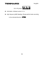
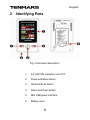
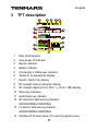
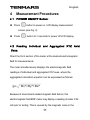
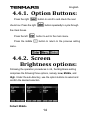
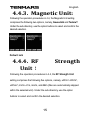
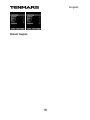
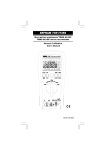
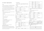
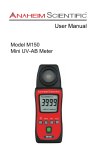
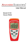
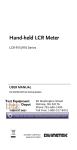
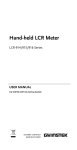
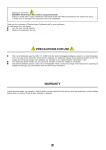
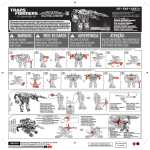
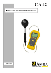
MULTI-FIELD EMF METER TM-190 User’s Manual 1 English HB2TM1900000 2 Meun 1 Features ............................................................................. 5 2 Identifying Parts.................................................................. 8 3 TFT description .................................................................. 9 4 Measurement Procedures................................................ 11 4.1 POWER ON/OFF Button:............................................ 11 4.2 Reading Individual and Aggregated XYZ Axial Data: . 11 4.3 Data hold (HOLD):....................................................... 12 4.4 Menu Settings: ............................................................ 12 4.4.1. Option Buttons: 14 4.4.2. Screen Brightness options: 14 4.4.3. Magnetic Unit: 15 4.4.4. RF Strength Unit: 15 4.4.5. Language: 17 4.4.6. Power Off Time: 19 4.4.7. Sound on/off: 20 4.4.8. Keys/Alarm Sound: 21 4.4.9. Keys Sound: 22 3 English 5 4.4.10. Alarm Sound: 22 4.4.11. Information: 23 Specifications ................................................................... 25 5.1 Sensor type: LF Magnetic Fields (MF)........................ 25 5.2 Sensor type: LF Electric Fields ................................... 25 5.3 Sensor type: RF Strength............................................ 27 6 Battery replacement ......................................................... 29 7 External USB power supply: ............................................ 30 8 Safety and maintenance standards ................................. 31 9 End of life.......................................................................... 32 4 English 1 Features Data hold (HOLD) LOW Low battery indication: HIGH Over load display “OL”. ” External USB Power Supply: ” Brightness options: low-Middle-high Magnetic unit:Gauss(mG) or. Tesla(uT) RF Strength Unit: (uW/m² ~mW/m²) (μW/cm²) (m V/m ~V/m) (mA/m) (dBm). Languages: English; Traditional Chinese; Simplified Chinese; Japanese; Español. Power Off Time:No; 1; 3; 5; 10; 15; 30. Factory default sets as “5”. Settings can be changed by the user. is displayed on the screen after power off time is set. Keys/Alarm Sounds: On ; Off Low-Frequency EMF Readings: Individual and aggregated XYZ axial readings . RF Historical Records: 5 English Up to 20 groups . Information: Software version: V1.0 High-frequency EMF Readings: Please perform tests according . to the indicated direction 6 TM-190 English Electric field Measurement Precautions: Please perform tests . Please according to the indicated direction hold the meter at the bottom of the display, as shown in the figure below: Fig. 1 Electric Field measurement: Magnetic Fields Electric Field RF stren gth Th e Green zone 0~10.00mG 0~500V/m 0~0.99mW/m²;0~0.59V/m The Yellow zo ne 10.01~100mG 501~1000V/m 1~9.99mW/m²;0.6~1.9V/m The Red zone 101~2000mG >1001V/m >10mW/m²;>2V/m The color zones are for reference only 7 English 2 Identifying Parts Fig. 2 Instrument description: 1. 2.4” 240*320 resolution color TFT. 2. Power and Menu button 3. Hold and Enter button 4. Select and Down button 5. Mini USB power interface 6. Battery cover 8 English 3 TFT description 1 Data Hold indicator. 2 Auto power off indicator. 3 Buzzer indicator. 4 Battery indicator. 5 Connecting a USB power indicator. 6 Tesla(uT) or Gauss(mG) display. 7 Electric Field (V/m) display. 8 9 RF strength history histogram display. RF strength digital (mV/m/ W/m²/μW/cm²/dB) display. 10 Menu key indication 11 Hold/ Enter key indicator 12 RF electronic field warning indicator: GOOD/NORMAL/WARNING. 13 LF electric field warning indicator: GOOD/NORMAL/WARNING. 14 Individual XYZ axial value of LF electromagnetic wave 9 English display 15 LF electromagnetic wave warning indicator: GOOD/NORMAL/WARNING 10 English 4 Measurement Procedures 4.1 POWER ON/OFF Button: Press button to power on. LCD display measurement screen.(see Fig. 3) Press button for 3 seconds to power off LCD display. 4.2 Reading Individual and Aggregated XYZ Axial Data: Direct the front section of the meter at the desired electromagnetic field for measurements. The meter simultaneously displays the electromagnetic field readings of individual and aggregated XYZ axes, where the aggregated calculation equation can be expressed as follows: Because of environment-related magnetic field factors, this electromagnetic field EMF meter may display a reading of under 0.50 mG prior to testing. This is caused by the magnetic noise in the 11 English environment, rather than meter failure. 4.3 Data hold (HOLD): to activate the HOLD function and Press the left button as hold the current readings at the upper left of the display. To release the held data, press the left Press the middle button again. button for 3 seconds to power off the meter. 4.4 Menu Settings: On the measurement screen: Press the middle button to enter the main menu, where 7 options can be selected, namely, Brightness, Magnetic unit, RF Strength Unit, Language, Power off, Sound, and Information. Press the right button to make the blue brick scroll down. Press the right button repeatedly, and the blue brick will cycle through the options. Press the left button to enter the selected option. Press the 12 English left button again to exit the selected option and return to the main menu. Press the middle button to return to the previous menu. 13 English 4.4.1. Option Buttons: Press the right button to scroll to and check the next button repeatedly to cycle through check box. Press the right the check boxes. Press the left Press the middle button to exit to the main menu. button to return to the previous setting menu. 4.4.2. Screen Brightness options: Following the operation procedures in 4.4, the Brightness setting comprises the following three options, namely, Low, Middle, and High. Under the sub-directory, use the option buttons to select and confirm the desired selection. Default: Middle 14 English 4.4.3. Magnetic Unit: Following the operation procedures in 4.4, the Magnetic Unit setting comprises the following two options, namely, Gauss/mG and Tesla/uT. Under the sub-directory, use the option buttons to select and confirm the desired selection. Default: mG 4.4.4. RF Unit: Strength Following the operation procedures in 4.4, the RF Strength Unit setting comprises the following five options, namely, uW/m²~mW/m², uW/cm², mV/m~V/m, mA/m, and dBm (files are automatically skipped within the selected unit). Under the sub-directory, use the option buttons to select and confirm the desired selection. 15 English Default: uV/m² ~ mW/m² 16 English 4.4.5. Language: Following the operation procedures in 4.4, the Language setting comprises the following five options, namely, English, Traditional Chinese, Simplified Chinese, Japanese, and Español (Spanish). Under the sub-directory, use the option buttons to select and confirm the desired selection. 17 English Default: English 18 English 4.4.6. Power Off Time: Following the operation procedures in 4.4, the Power Off setting comprises the following seven options, namely, NO, 1, 3, 5, 10, 15, and 30 (min). Under the sub-directory, use the option buttons to select and confirm the desired selection. Default: 5min 19 English 4.4.7. Sound on/off: Following the operation procedures in 4.4, the Sound setting comprises the following two options, namely, On and Off. Press the right box. Press the right Press the left button to scroll to and check the next check button to cycle thought he options. button to select the “Enable” setting and enter 20 English the Keys/Alarm Sound menu (Section 4.4.8). Press the left button to select the “Disable” setting and return to the main menu(Fig. 3). Press the middle button to return to the measurement screen 4.4.8. Keys/Alarm Sound: Following the selection of the Enable option in the Sound settings menu, the Keys/Alarm Sound setting comprises the following two options, namely, Keys and Alarm. Press the right button to scroll to and check the check the next check box. Press the right button repeatedly to cycle through the options. Press the left button to enter the next options screen. 21 English 4.4.9. Keys Sound: Following the selection of the Keys option in the Keys/Alarm Sound settings menu, the Keys setting comprises 3 options, namely 1, 2, and 3. Press the right box. Press the right button to scroll to and check the next check button repeatedly to cycle through the options. Press the left button to exit to the main menu. Default: 3 4.4.10. Alarm Sound: Following the selection of the Alarm option in the Keys/Alarm Sound settings menu, the Alarm setting comprises 3 options, namely 1, 2, 22 English and 3. Press the right box. Press the right button to scroll to and check the next check button repeatedly to cycle through the options. Press the left button to exit to the main menu. Default: 3 4.4.11. Information: Following the operation procedures in 4.4, select the Information option to display the software version (V1.0). Press the left Press the middle button to exit to the main menu. button to return to the settings screen. 23 English 24 English 5 Specifications 5.1 Sensor type: LF Magnetic Fields (MF) The meter is equipped with three individual aerial sensors to measure EMFs. The overload indications can be displayed simultaneously on three axes (X, Y, Z): Range: 20/200/2000mG, 2/20/200µT. Resolution: 0.01/0.1/1 mG or 0.01/0.1/1 µT. Frequency response: 50/60 Hz Sensor: Triple Axis (X, Y, Z). Accuracy: ±(15%+100dgt). 5.2 Sensor type: LF Electric Fields 25 English Range: 50V/m to 2000V/m. Frequency response: 50/60Hz Accuracy: ± (7% ± 50dgt). 26 English 5.3 Sensor type: RF Strength Frequency range:50MHz to 3.5GHz. Accuracy: ± 2dB at 2.45GHz Measurement units: uW/m²~mW/m²; μW/cm²; mV/m~V/m, mA/m, and dBm Specified measurement range:(0.01uW/m² to 484.6uW/m²) (0.01uW/cm² to 44.4uW/cm²) (36.1mV/m to 13.90V/m) (0.01mA/m to 30.01mA/m) (-46dBm to 16dBm). Display resolution: 0.01μW / m², 0.1μA / m, 0.1mV/m, m, 0.001μW/cm ², 1dB. Display: 4 digits Triple LCD display. Sample rate: 6 seconds per time. Battery life: Approximate 8 hours. Battery: 1.5V AAA Alkaline Battery*3. Audible Key tone alarm: Buzzer 27 English Operating temperature & humidity: 5°C to 40°C, below 80% RH. Storage temperature & humidity: -10°C to 60°C, below 70%. Weight: About 120g. Dimensions: 115(L)*60(W)*21(H) mm. 28 English 6 Battery replacement WARNING If the symbol “ ” appears on the screen, please replace the battery immediately Turn off the instrument. Open the battery covers and remove the battery. Take three new 1.5VAAA alkaline batteries, and install the batteries according to the polarity. Put back the battery cover. 29 English 7 External USB power supply: External USB. Specifications: Voltage DC 4.8 ~ 5.2V current ≧ 500mA. A icon is displayed when an external USB power supply is connected to the meter. The meter determines connected USB cables to be antennas, and thus such cables should not exceed the top rim of the buttons during testing. If the cables exceed this limit, the readings of subsequent tests are considered invalid. 30 English 8 Safety and maintenance standards Do not operate around combustible gases or in damp environment. Operating altitude: below 2,000m. Operating environment: for indoor use, expose to pollution level II. This is a precision device. During use or storage, do not go beyond its spec. to prevent any possible damage or danger. Do not put this device in direct sunlight or where it is hot and/or damp. For long storage, remove the battery to prevent the battery from leaking and causing damage to the parts inside. Clean the device with a dry soft cloth. The use of wet cloths, liquid and water is prohibited. 31 English 9 End of life Caution This symbol indicates that equipment and its accessories shall be subject to a separate collection and correct disposal 32 English Professional Electrical and Environment Test & Measurement Instruments: Battery Capacity/Impedance Tester, TACHO Meter, LED light meter, Temperature & Humidity meter, Infrared Thermometer, Sound level meter, Light meter, EMF meter, UV Light meter, RF meter, Hot wire Anemometer, CO meter, Anemometer, Lan cable tester, CO2 meter, Solar power meter, Radiation meter, Clamp meter, Multimeter, Phase Rotation test, Digital Insulation tester. TENMARS ELECTRONICS CO., LTD 6F, 586, RUI GUANG ROAD, NEIHU, TAIPEI 114, TAIWAN. 33