1
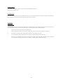
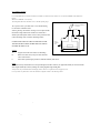
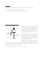
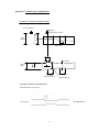
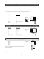
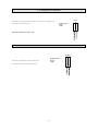
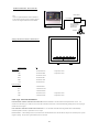
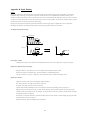
FLOW HUNTER
Ultrasonic Open Channel Flow
Measurement
User Manual
Security Code Default = 1
ECHO Process Instrumentation, Inc.
Ship to: 70 6th Ave.
Mail to: PO Box 800
Shalimar, FL 32579 USA
Phone: 850-609-1300
Fax:
850-651-4777
Email: [email protected]
Website: www.echopi.com
© Copyright Notice August 2009
CONTENTS
Page
1.0
Introduction
1
2.0
Operating and Programming
2
2.1
Run Mode
3
2.2
Main Menu
4
2.2.1
Quick Set-up
5
2.2.2
Set-up relays
9
3.0
2.2.3
Advanced Set-up
2.2.4
Reset Totalizer
10
12
2.2.5
Review Set-up
12
12
Mounting Instructions
3.1
Transducer Mounting
13
3.2
Correct Location
14
3.3
Blanking Distance, Deadband and Safety Procedure
14
APPENDIX A
Primary Measuring Device Types and Dimensions
15
APPENDIX B
Overview of Terminal Connections – Flow Hunter
17
Connections and Wiring
18
APPENDIX C
All Terminal Connections
19
APPENDIX D
Fault Finding
23
1.0 Introduction
T h e Flow Hunter instrumentation unit is for use in conjunction with the Xducer 06 non-contact ultrasonic sensor head. The Flow Hunter
is a fully programmable open channel flowmeter conforming to US and UK BS3680 calculations for the following channels:
Model
Xducer 06
Range
Liquid
9.8 – 236 in
(0.25 – 6 m)
-
V-Notch Weir
Rectangular Weir
Rectangular Flume
25 Point Table (X,Y)
Parshall Flume
Palmer-Bowlus Flume
Manning Equation (Pipe)
The Flow Hunter measures.
(i). Volumetric Flow.
(ii). Total Flow.
Time
of
Flight
(d)
(iii). Distance.
(iiii). Temperature.
The head measures the time of flight of an ultrasonic pulse to travel from the sensor to
the reflecting surface and back to the transducer. This information is transmitted to the instrumentation unit where it is converted into distance
and flow information.
distance (d) = Time of Flight x Ultrasonic Velocity
2
The instrumentation unit contains a versatile fully
programmable computer which enables a number of
processing functions to be carried out. These functions
must be configured on first power up of the system. This is
known as ‘CALIBRATION’.
Programming the unit is simple as the unit is fully
menu driven and prompts the user for his preferred
choice.
Figure 1. shows the facia layout of the Flow Hunter.
On the front panel facia you will find the LCD display,
the Alarm Set LED'sto the right and the Programming
Figure 1
Keys.
1
2.0 Operation and Programming
When installing the Flow Hunter, first install the transducer above the channel as per the instructions in Appendix A.
When power is first applied to the Flow Hunter, it will show the following messages on the LCD display quickly in succession:
This means the Flow Hunter is retrieving the system set-up data from the non-volatile memory.
Retrieving data
from EEPROM
ECHO PI Inc.
Flow Hunter
X.XX
Addr=0 Baud=96
32K CFG=2000
Flow
xx.xx GPM
Air Temp xx F
Displays the software version number
System information concerning the unit's RS485 address and Baud rate.
At this point the Flow Hunter will start to fire the Ultrasonic Head and display the flow rate and air
temperature, using the factory programmed default channel dimensions.
This is called ‘Run Mode’ and is the mode the Flow Hunter uses to display the volumetric
temperature, totalizer and distance.
To program the Flow Hunter, the user is presented with several menus each of which contain numerous options that can be toggled on/off
or a numeric value entered.
The menus are all presented on the display as a series of statements which ‘cycle round’ each time the ‘UP’ or ‘DOWN’ push-button is pressed.
To select a particular option, the user has to press the ‘ENTER’ button when the relevant menu option is displayed.
For all numeric values, the menu statement displays the currently programmed value and allows the user to increase or decrease th is v a lu e b y
pressing and holding ‘UP’ or ‘DOWN’. Pressing ‘ENTER’ will enter the new value into the system and overwrite the old value. If the old value is on
the display and the user presses ‘ENTER’, it has the effect of leaving the number unchanged. The push-buttons automatically repeat if held pressed.
The user will see the numbers displayed change slowly at first then increase in speed every few seconds as long as a push-button remains held
down. The Flow Hunter also emits a short ‘bleep’ as an acknowledgement of a key press or when the auto repeat function is in use (default is OFF).
2
2.1 Run Mode
The Flow Hunter will normally remain in ‘Run Mode’ displaying the flow information. All the relay outputs are active during th is m o d e .
Depending on the options programmed, pressing the ‘UP’ or ‘DOWN’ buttons will scroll the display through the following:
Flow
xx.xx GPM
Air Temp xx F
Displays the flow rate and air temperature in the Channel. The flow is displayed in Gallons per Minute (GPM) or in
other pre-set units and the air temperature in degrees Fahrenheit (oF).
.
Distance
xx.xx ft
Air Temp xx F
Total
Displays Distance from the transducer face to the water. If the PMD is empty, then this value is “No Flow Distance”.
xx.xx Gal
Air Temp xx F
Displays the totalized flow up to 999,999.99 Gal.
All the information regarding the shape and size of the channel, the head offset etc. are programmed into the
Flow Hunter in the calibration menus.
If the Ultrasonic Head should fail to receive echo's from the flow surface, the ‘Lost Echo’ error message is displayed. If the echo is lost for longer
than 20 seconds (user settable), the Lost Echo Relay will then be de-energised. The relay coil is re-energised when the echo
Lost Echo
Air Temp xx F
returns.
To bring the Flow Hunter out of ‘Run Mode’, press the ‘ENTER’ button. The unit will then ask for the
Security
Code ? x
Security Code number to be entered. The factory pre-set code number is indicated on the front cover of this
manual (1) but this can be changed by the authorised user at any time. Use the ‘UP’ or ‘DOWN’ buttons to
change the displayed number then press ‘ENTER’ to enter the code. If no code is entered within 12 seconds, the
Flow Hunter returns to run mode.
*** ERROR ***
INVALID ENTRY
If an incorrect Security Code is entered, this error message is displayed and the unit returns to ‘Run Mode’.
3
2.2 Main Menu
When the correct security code has been entered, the Flow Hunter stops firing the head, turns off all the relays and displays the main menu.
This is where the system set-up and calibration parameters can be entered.
The ‘UP’ and ‘DOWN’ buttons move the Flow Hunter through the following menu options:
Press ‘ENTER’ to select the required option.
Main Menu
Run Mode ?
Returns the Flow Hunter to ‘Run Mode’
Main Menu
Quick Setup?
Programs the flumes, weirs, lookup table and the ultrasonic head parameters.
Main Menu
Setup Relays?
Programs the relays parameters.
Main Menu
Programs the temperature, new password and RS485/RS232 data communications address.
Advanced Setup?
Main Menu
Reset Totalizer?
Main Menu
.
Resets the Totalizer to zero.
Displays the final parameters programmed as a list.
Review Setup?
Each of the above menus should be programmed as appropriate when first installing the Flow Hunter.
Definition of Terms:
No flow distance
Distance from sensor face to zero (0) flow point in Primary Measuring Device in inches. Used to calculate
the span and fixes the 4mA output value to 0%.
Max. Flow Height
Distance from zero (0) to maximum (100%) HEAD (Level) height in inches corresponding to maximum flow.
This is used to calculate the flow span and fixes the 20mA output value to 100%.
Span
Calculated flow span = ( max. flow - min flow (zero) ). This calculates the Max Flow based on the “Max. Flow Ht” given.
This should agree with your flow calculations.
Blanking Distance
Minimum = 9.84 inch (0.25 meter).
Should be increased as required to overcome interfering objects / structures between the sensor and maximum
flow height. Such interference can lead to a false echo.
4
2.2.1 Quick Set‐up The “Quick Set‐up” menu is where the Primary Measuring Device and the ultrasonic transducer parameters are entered into the Flow Hunter. Flow Chart: V Notch Weir. For dimensional definitions see Appendix A. 5 Flow Chart: Rectangular Weir. For dimensional definitions see Appendix A. Flow Chart: Rectangular Flume. For dimensional definitions see Appendix A. Flow Chart: X,Y Table. Flow Chart: Parshall Flume. For dimensional definitions see Appendix A. Flow Chart: Palmer‐Bowlus Flume. For dimensional definitions see Appendix A. Flow Chart: Manning Equation (PIPE). 2.2.2 Setup Relays
The ‘Set-up relay’ menu is where the programmable relay information is entered into the Flow Hunter.
The relays can be programmed via the ‘Set-up relay’ option of the main menu. There are 4 relays on the Flow Hunter of
both Normally Open (NO) and Normally Closed (NC) configuration.
The 4 relays on the ECHO Flow Hunter can be programmed individually to switch on the following choices:
Flow
Sampler
1.
High flow LEVEL alarm based on a maximum level value
2.
Low flow LEVEL alarm based on a minimum level value
3.
Pulsed every xxx ft3
Once you have selected ‘Set-up relay’ you may cycle through these choices until you select one of them. You will then be asked to enter the
appropriate values.
Main Menu
Setup relay ?
Relay Number ?
Relay Number ?
Choice = Relay 1
Choice = Relay n
Relay Menu
Disable relay ?
Relay Menu
Sampler ?
Relay Menu
Level switch ?
Relay Number ?
Choice = Relay 1
Relay Number ?
Relay Number ?
Relay Number ?
Main Menu
Choice = Relay n
Choice = Relay 1
Choice = Relay n
Setup Relay ?
High / Low alarm? High / Low Alarm?
Pulse every ft3
Saving to
Choice = Low
> xx.xx
EEPROM
Choice = High
Relay Menu
Exit ?
Main Menu
Setup relay ?
Accept data ?
Accept data ?
Accept data ?
ANS = NO
ANS = YES
EXIT
Saving to
EEPROM
Main Menu
Setup relay ?
9
2.2.3 Advanced Set-up
In this menu, the settings of the unit address (RS485 only), temperature compensation, operator security code and Lost Signal settings can be changed.
The menu structure is displayed below:
Main Menu
Advanced Setup?
Setup Syste
Unit Number ?
Unit Address ?
> xx.xx
Setup System
New Password ?
Setup Syste
Select temp ?
Temp is internal ?
Change ? NO
Tank temp deg C
> xx.xx
Temp is external ?
Change ? YES
Tank temp deg C
> xx.xx
Saving data
to EEPROM
Main Menu
Advanced Setup?
10
Change Password ? Change Password ?
ANS = YES
ANS = N
Enter New Code
> xx.xx
4 - 20mA Output
The unit is provided with a 4-20mA isolated output as standard.
The 4-20mA output is automatically scaled to the selected span (max flow height) you have programmed.
e.g. If you have programmed a span of 50 GPM then the unit will output 4mA as Zero (0) flow and 20mA as max. flow ( 50 GPM )
Lost Echo :
The Lost Echo function is signalled on the 4-20mA output as 0mA (i.e Open Circuit). To ensure the unit fails to a safe condition u n d e r p o w e r
loss or malfunction the lost echo function must always be used.
NOTE :
The velocity of sound changes by 0.18% per oC change in temperatures.
11
2.2.4 Reset Totalizer
It will display “Clear Totalizer, Change ?” Select “YES” and press ENTER password “120”.
It will then show “Totalizer Clear”.
.
2.2.4 Display Set-up
In this menu, the settings of the unit can be confirmed. Press any key to scroll through the display (it will loop back to Review Setup at the end).
This is a useful way to view that all programmed parameters have been correctly entered.
3.0 Mounting
Transducer Location
Correct positioning of the sensor is vital if accurate results are to be obtained. A basic error in installing the sensor will cause inaccuracies in all
other aspects of flow metering. The sensor must be held rigidly over the channel and directed towards the liquid face.
i.
Locate the sensor at least 18 inches above the maximum level.
ii.
Ensure that the ultrasonic beam has a clear path to its target and is not going to strike objects on the wall of the channel.
iii.
Fix the sensor in a vertical position. Hand-tighten the transducer to avoid ringing in the winter.
iv.
Try to avoid situations where the temperature sensor is exposed to sunlight especially at dawn and evening.
v.
In the event of the transducer being exposed to prolonged strong sunlight a simple heat-shield erected above the sensor will ensure
correct temperature compensation in the most severe conditions. A suitable shield is available from ECHO PI.
12
3.1 Transducer Mounting
It is recommended that the Ultrasonic transducer is mounted on a bracket above the channel to overcome the deadband of the transducer as
follows :
Xducer 06 - Deadband = 9.84” (0.25m)
This arrangement allows the transducer to cover the full operating range.
To Remote Transducer Drive
or Instrument
The top of the sensor is provided with a 1” NPT thread allowing
it to be bolted to a suitable bracket.
1” NPT Thread
When tightening the transducer securing screw it is important that
1”
the natural turning moment of the transducer is resisted with a
suitable open-ended spanner. Failure to observe this precaution could
result in the damage of the transducer. Hand-tight ONLY.
UNDER NO CIRCUMSTANCE SHOULD THE BODY OF THE
3.75”
Integral
temperature
sensor
TRANSDUCER BE CLAMPED, EITHER WHILE IT IS BEING
SECURED OR WHEN IN USE.
NOTES
2.75”
A.
Support and restrain sensor cables to avoid damage.
B.
Route sensor cables away from power cables and other
sources of interference.
C.
Where cables pass through a junction box, maintain continuity of the screen.
NOTE
You will have been provided with the correct/requested length of transducer cable for your application-should you wish to extend this
cable length it should only be done by adding to the existing length through an IP68 gland.
Always use the nut provided and insert the damping washers. Do not over-tighten the nut as ringing may occur.
Use a sprit level or a plumb line to ensure the transducer is aligned "normal" to the reflecting surface.
13
3.2 Correct Location
The transducers should be placed such that the ultrasonic beam does not reflect from interfering structures during it's flight path.
The beam spread for the ultrasonic wave as it travels from the transducer is 6 degrees.
Ensure that at the maximum distance to be measured, the beam does not collide with interfering structures.
3.3 Blanking Distance, Deadband and Safety Procedure
There may be instances where obstructions in the channel give rise to false
echoes. If such obstructions are above the maximum level to be measured
then they may be gated out by instructing the computer to ignore any
Transducer
return echo in the flight path up to such an obstruction. This is performed
in the calibration mode by programming in a blanking distance. The
blanking distance programmed should be the distance from the transducer
to 9.8 inches (0.25m).
Deadband (X)
(Fixed)
All ultrasonic transducers have a blind area called the "deadband". Within
Blanking Distance
this area the sensor cannot detect the true echo. This should be borne in
mind when setting up the unit since if you allow your liquid to fill into this
area the instrumentation unit will not return lost echo but give an
X + 20%
erroneous reading which relates to a multiple echo, which in the time base
Safety Zone
is perceived to be outside the deadband region.
In order to prevent this occurrence you should always assign one of the
relays to a high alarm condition.. The level of this high alarm must be
below the dead band zone which is given in inches in the Quick Setup menu for each head type. It is recommended that you make this alarm
setting equal to the distance of the deadband plus 20%. For example an Xducer 06 head with a deadband of 9.8 inches should have a high level alarm
set at a distance of 12 inches from the surface of the transducer head.
A safety margin of 2 inches above the blanking zone should be sufficient for most applications.
14
Appendix A: Channel types and dimensions
Transducer Location For Rectangular Flumes
Ultrasonic Transducer
Stilling Well
(optional transducer location)
Dead
Band
No Flow
Distance
100
Span
FLOW
0%
Side Elevation
Throat Width
Channel
Width
(b)
3 to 4 x Span
Ultrasonic transducer
Throat Length (L)
Approach Width (B)
Transducer Location For Parshall Flumes
Mount the transducer 2/3 L upstream.
Flow Upstream
Flow Downstream
15
Transducer Location For Weirs
A
4 to 5 h
Dead
Band
No Flow Distance
Max Flow
Height = 100%
Head
h
Range
Inlet Section
Section A-A For V-Notch
Outlet Section
A
Approach Width (B)
Weir Plate
Dead
Band
No F low
Dista nce
Max. Flo
Height
Sill
Height
Head
h
Range
Position transducer
on center line
Outlet
Sill Width
16
Appendix B: Overview of Terminal Connections for Flow Hunter
All connections to the unit are located on the rear section of the unit housing. The Ultrasonic Transducer has been supplied with 10m
standard cable unless ordered with longer length with the wires labelled ( see Connections and Wiring ). A weatherproof IP68 gland
must be used to make any termination's or when extending cable length. Access into the transducer will invalidate the guarantee.
All wiring must be to the latest IEEE regulations.
Power Connections
The unit can be powered from mains 110/230VAC (24VDC is ordered separately). The details of the Power connections are given in the diagram below.
The Power drawn is 5 Watts.
Fuse Rating : 20mm 1A Anti-surge
Relay Connections
There are 4 programmable relays. These relays have both normally open (NO) and normally closed (NC) contacts so that they can be used in any
configuration.
The ratings for the relays are as follows:
Max. Switched current and voltage
1A @ 24VDC
Electrical life at full load
min. 8 x 10⁴ operations
Mechanical life
min. 5x10⁶ operations
Communications
The RS232 is factory set to:8 Data bits
1 Start bit
1 Stop bit
No Parity
The data is fixed at 9600 baud.
The information format is an ASCII string of characters that is terminated by a ZERO character before the information is repeated.
17
Connections and Wiring
Relay 1
RL1
Common
COM
Normally Closed
NC
Normally Open
NO
RL 1
Relays
Relay 2
RLn
RL2
Common
COM
Normally Closed
NC
Normally Open
NO
Xducer
+VE
(empty)
0V
(empty)
SCR (SHIELD)
RET
RED
TR
BLACK
TM+ WHITE
TMGREEN
Transducer
Shield
RET
RED
TR
BLACK
TM+
WHITE
TM-
GREEN
L
LIVE
N
NEUTRAL
E
EARTH (Ground)
+VE
0V
4-20mA
+Ve (+)
SCR
COM
N.C
N.O
Analog
4-20mA Isolated
0V (-)
COM
N.C
N.O
Power Supply
Supply
L
N
E
Cable type: 4 Conductor Cable, Shielded. Max. current per Core 1A. Max. Temp 70 deg C.
Transducer Remote Driver
If the transducer cable exceeds 50m (150’), a remote driver interface box is required for extended runs. The connection
to this driver is via a 6 core cable type Defence Standard 61-12, Sub miniature Cable Specification 16-2-6C.
See page 22. Connection details are printed on the rear of the units
18
Appendix C: All Terminal Connections for Flow Hunter
All connections to the unit are located in the lower section of the unit housing. Access to this area does not invalidate the guarantee.
All wiring must be to the latest IEEE regulations.
The unit supply voltage must be provided via a double pole spur.
Mains Connection
The units are factory set to operate from either 115V or 230V, 50Hz mains. This is indicated on the
rating label adhered to the unit.
CTR3
Printed Circuit
Board
(PCB)
Fuse Rating :- 20mm 250V, 250mA Anti-Surge.
L N E
The diagram shows the connections for Live, Neutral and Earth.
Relay Connections
There are 4 programmable relays and 1 lost echo relay that are available to external circuitry. These relays have both normally open ( NO ) and
normally closed (NC) contacts so that they can be used in any configuration.
The ratings for the relays are as follows:
Max. Switched current
5A
Max. Switched voltage
30V DC / 250V AC
Electrical life at full load
min. 8 x 10⁴ operations
Mechanical life
NC
COM
NO
7
min. 10 operations
The connections for the relays are shown below
Printed Ciruit
Board
(PCB)
CTR5
CTR6
CTR7
RELAY 1
RELAY 2
RELAY 3
CTR8
CTR9
RELAY 4
LOST
ECHO
Lost Echo Relay :
Normal procedure for the lost echo relay would be to connect the NO and COM terminals
since this relay is energised during normal operation of the transducers.
Relay 1
On a lost echo condition the relay is de-energised.
Relay 2
Relay 3
The L.E relay should be used as a fail-safe relay connected in series with the other 4
L.E
Relay
programmable relays. The ensures that all power to external equipment is removed when the
Flow Hunter is not in the 'Run Mode' or if there is a power failure to the unit. If the L.E relay is
not used, any equipment connected to the NC connections of the other relays will run if power is removed because these relays
will de-energise. i.e. NC contact is made.
19
Relay 4
Transducer Connections from Enclosure to Remote Transducer Driver J-Box (long cable run only)
The connections for the ultrasonic head is shown below. Normally the head uses four wires, red, green, white and white as indicated in the table
below.
T h e ‘ T H E R M I S T O R ’ c o n n e c tio ns relate to the temperature sensor associated with the ultrasonic head.
Connection
Head Cable Color
+VE
Red
CTR10
0V
Green
SCR
Screen
RTN
Blue
CTR11
Printed Cicuit
Board ( PCB )
Note
Ensure connector
block from
transducer is
correctly wired
TR
Yellow
Thermistor +
White OR Temperature sensor
Thermistor -
Black
"
"
"
Transducer Connections with Internal Transducer Driver (Standard)
Connection
Head Cable Color
+VE
No Connection
0V
No Connection
SCR
Shield
RET
Red
TR
Black
Thermistor + (TM+)
White (Temperature sensor)
Thermistor – (TM-)
Green (Temperature sensor)
CTR10
CTR11
Printed Circuit
Board
(PCB)
Communications
The RS232/422 is factory set to:
CTR14
8 Data bits
Printed Circuit
Board
(PCB)
1 Start bit
1 Stop bit
No Parity
The data rate is fixed at 9600 baud. The information format is an ASCII string of
characters that is terminated by a ZERO character before the information is repeated.
The connections are as shown.
Printer
---------------
20
Low Voltage Power Connections
CTR4
The unit can be powered from either 24 Volts AC or 24 Volts DC. The details of the
Printed Circuit
Board
(PCB)
low Voltage power connections are:-
THIS MUST BE FACTORY SET
4 - 20mA Output
CTR12
Printed Circuit
Board
(PCB)
The unit can be provided with a 4-20mA output option.
The terminal connections for this are shown below:
+ 0V
21
Installation With Remote Driver Electronics
Remote Driver
Note:
If you have specified the distance from the instrument
Up to 5,000 ft
to the transducer less than 50m, the instrument supplied
POWER
will have an integral transducer driver board built in.
Up to 150 ft (50m)
max. distance from
Transducer to
Remote Driver
Instrumentation
Transducer
Wiring Connection For Remote Transducer Driver
From
Transduce r
X1
X2
S CN
TH1 TH2
TH1
TH2 TRI G R TN GND +15V
To Instrument
From Transducer
CONNECTION
To Instrument
ID
To Instrument
TH1
- Instrument White
: Temperature sensor
TH2
- Instrument Black
: Temperature sensor
TRIG
- Instrument Yellow
RET
- Instrument Blue
GND
- Instrument Green
+15V
- Instrument Red
From Transducer
X1
- Transducer Red
SCN
- Transducer Screen
X2
- Transducer Black
TH1
- Transducer Green
: Temperature sensor
TH2
- Transducer White
: Temperature sensor
Cable Type and Cable Installation:
From Instrument to Remote Transducer Drive Electronics: Defence Standard, 61-12 Sub-miniature Cable Specification 16-2-6C. It is
essential to use this cable type or cable with cores in the same orientation. Failure to do so will cause fluctuating readings due to cross coupling of
transmit and receive signals.
From Transducer To Remote Transducer Drive Electronics : 4 Core Screened twisted Pair with Integral Drain Wire And Individually
Screened. Impedance 54 ohms, Capacitance core/core 115pF.
G e n e r a l N o te s : Where multiple sensors are connected to the instrumentation ensure that the cables are kept at least 12 inches apart to prevent
magnetic coupling.. Always ensure grounds and screens are connected.
22
Appendix D: Fault Finding
Ringing
When in the transmit mode, ultrasonic transducers convert electrical energy into mechanical energy causing the transducer to vibrate, like a
loudspeaker. Most of this energy is converted into an ultrasonic acoustic wave but some is transmitted into the transducer housing. This is
analogous to striking a bell whereby you hear a sound but also you can observe the bell mechanically "RINGING". If this is excessive it will take
a long time to die away and can still be present when the return echo arrives back at the transducer. In such cases the transducer cannot recognize
the returning echo and as a result the system cannot calculate range.
Ringing can be recognised by a higher than expected level indicated. To reduce ringing always use gaskets and never over-tighten bolts.
Hand tighten the transducer. Increasing the blanking distance beyond the ringing time will also lock out its effect.
No Display showing FMP not firing:
Transmit Pulse
Transmit
Ringing
Time
Ringing
R ec e i v e
Damping
Return echo
Ringing
Return echo
Check supply to FMP.
Carefully unscrew the four screws and remove facia label plate and check fuse, if blown replace with 1.0 Amp anti-surge fuse.
Display shows higher than expected reading:
Ringing of transducer - check bolts have not been over-tightened and the damping washer is fitted.
False echo from object in transmission path - reposition transducer or extend blanking distance.
Velocity of sound not set correctly - re-program to correct temperature setting or install new temperature sensor.
Display shows lost echo:
Transducer incorrectly wired - check wiring diagrams against installation.
Poor wiring connection - ensure all wires are securely connected.
Poor Earth - meter earth connection and rewire if necessary.
Liquid level has entered the blanking zone and / or the near field - reduce level until reading returns (see Section 3.2)
Stilling well has curved bottom and is empty - this will cause the ultrasonic signal to bounce around the well arriving back at the
transducer outside its permissible time for the set height - ensure transducer is positioned as central as possible and the well always
has liquid present below the transducer.
Foam present - foam absorbs ultrasound - reposition transducer away from foam. Placing in a stand (stilling pipe) pipe will suffice
provided foam does not penetrate the pipe.
Temperature thermals - foam occasionally present; use stand pipe
23
Display shows periodic lost echo:
Large undulating surface associated with very turbulent liquids causing unfavourable reflecting surface; reposition transducer ab o v e
flattest surface or in the case of liquids use a stilling pipe.
Transducer not mounted to the normal reflecting surface - using a spirit level realign transducer.
Ultrasonic beam occasionally catches edge of weir tank or flume; Lower transducer or place in stilling pipe.
Temperature fluctuations:
Damage to thermocouple - using a multimeter check the resistance of the thermocouple. It should read between 400 ohms and 100K
ohms depending on the temperature being measured. ( 10K ohms @ 25 deg. C )
Display fluctuates :
Periodic lost echo - check all factors above.
Totalizer gives lower than expected readings
Low flow rate operating outside the BS standards. Increase flow rate through weir.
24