1
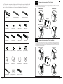
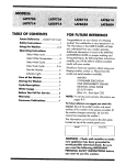
SStep
te p2 2
Mounting
the Wall
to Plate
the Wallto
Mounting
thePlate
Wall
the Wall
BBrick,
rick,Solid
S
o liConcrete
d Concret
e mounting:
Mounting:
Use
the wall
Wall
Plate(a)
a template
6 hole locations
theinwall.
Three
in slots,
the top
of slotsrow.
andMake
three more in the
Use the
plate
(a) as aas
template
to markto6 mark
hole locations
on the wall.on
Three
the top
row of
3 inrow
the bottom
bottom
row.
Make
sure
these
holes
are
level
and
there
is
at
least
6"(150mm)
distance
between
any
two
sure these holes are level and there is at least 6” (150mm) distance between any two holes. Pre-drill these holes with a 3/8” holes. Pre-Drill
these
with
masonry
bit Insert
to at aleast
3"(75mm)
in into
depth.
Concrete
intois each of these
(10mm)holes
masonry
bitato3/8"(10mm)
at least 3” (75mm)
in depth.
concrete
anchor (x)
eachInsert
of thesea holes.
Make Anchor(x)
sure the anchor
holes.
sureflush
the with
anchor
is seated
completely
flush
concrete
surface
even
there
is a the
layer
drywall or other
seated Make
completely
the concrete
surface
even if there
is with
a layerthe
of drywall
or other
material
in if
front.
Attach
wallofplate
material
front.
Attach
Plate
to the
using
6pcs 2A.
Lag Bolts(v) and 6pcs Lag Bolt Washers(w), shown in
to the wallinusing
6 lag
bolts (v)the
andWall
6 lag bolt
washers
(w),wall
shown
in Diagram
Diagram 2A.
Model
KMFMX2
Model
FMC3
Assembly Instructions
WWood
ood Stud
StudMounting:
mounting:
The
Wall
Plate(a)
ust
be m ount
edwood
to tstuds
w o watleast
ood st
at least
m ) apart
. Use
stud finder
The wall plate
(a) mustmbe
mounted
to two
16”uds
(406mm)
apart.16"
Use (
a406m
stud finder
to locate
twoaadjacent
studs. to locate two
adjacent
studs.
is a good
to verify
wherewith
theanstuds
with
an awl or
nail ashown
in Diagram
2B. Pre-drill
It is a good
idea toItverify
whereidea
the studs
are located
awl orare
thinlocated
nail shown
in Diagram
2B.thin
Pre-drill
3” (75mm)
deep
ahole
3"(75mm)
deepheight
hole inateach
the stud
desired
in each
studMake
using
5/32"(4mm)
drill
Make
sure
these
at the desired
using height
a 3/16 (5mm)
drill bit.
sureathese
holes are in
the bit.
center
region
of the
studsholes are in the
and level
withof
each
thelevel
wall plate
a template
mark
the
location
of as
theasecond
hole to
in each
3” (75mm)
center
area
theother.
studsUse
and
with as
each
other. to
Use
the
Wall
Plate
template
markstud.
the Drill
location
of the second hole
holes
using
a 3/16”
(5mm) drill
bit holes
in the marked
Attach the
wallbit
plate
to the
wall using
the 4 lag Attach
bolts (v) the
and Wall
4 lag Plate to the
indeep
each
stud.
Drill
3"(75mm)
deep
using locations.
the 5/32"(4mm)
drill
in the
marked
locations.
bolt using
washers
(w).4pcs Lag Bolts(v) and 4pcs Lag Bolt Washers(w).
wall
the
Diagram
D iagram 2B
2B
Diagram
D iagram 2A
2A
a
v w
SStep
te p3 3
x
Attaching
Monitor
to Wall
Wall
Plate
Attaching
the Monitor
to the
Plate
S tud Finder
stud
finder
16 n
i ch
16 n
i ch
16 n
i ch
and Adding the Safety Bolts
CAUTION
The maximum loading weight is 80 lbs (36 kg). This wall mount is intended for use only with the maximum weights indicated.
Use with products heavier than the maximum weights indicated may result in instability causing possible injury.
TV Size: 32 inch to 50 inch. See apparatus instructions.
Thank you for choosing Kanto AV Systems flat panel wall mount. The FMC3 is designed to
mount flat panel televisions weighing 80 lbs (36 kg) or less (see Caution above). This mount
will tilt your TV ±15º and swivel (pan) left and right without the use of tools. You can also fine
tune the horizontal by rotating the mount 2º after the mount it is fixed to the wall.
may
two people
lift! We
not
forresponsi
personal injury
or product
damage.
WWarning:
arning:Some
S omTVs
e TV
s require
may requi
re t
w oto
peopl
e tare
o li
ft! responsible
W e are not
ble for
personal
injury or productdam age.
First
hook the Monitor Brackets(b,c) over the top of the wall Plate(a), then let the bottom of the Monitor Brackets rotate to
Hook the monitor brackets (b,c) over the top of the wall plate (a), then lower the monitor brackets to clasp the bottom of the wall
the
bottom
of the
Wall Plate
asashown
in thetoDiagram
Use
the The
screw
driver
to tighten
safety
bolts. Then
the Monitor
plate
as shown
in Diagram
3A. Use
screw driver
tighten the3A.
safety
bolts.
monitor
bracket
will sit the
behind
the bottom
tab
Bracket
willplate
sit behind
bottom 3B.
tab on the Wall Plate as shown in the Diagram 3B.
on the wall
as shownthe
in Diagram
Diagram
D iagram3A
3A
3B
DDiagram
iagram 3B
Read these instructions fully before installation of this mount. If you do not understand these directions, or
have any doubts about the safety of the installation, please consult a qualified installation contractor to install
this mount.
Make sure there are no defective or missing parts. Do not use defective parts. If you are uncertain if the part is
defective call Kanto AV Systems directly at 1-(888) 848-2643. Kanto AV Systems can not be liable for property
damage or injury caused by incorrect mounting, incorrect assembly, lifting or incorrect use of this product.
This product should NOT be mounted on steel stud walls or cinder block walls. Consult a qualified installation
contractor if you are unsure about the type of wall you may have. We make every effort to assure all necessary
hardware is included. If there is hardware missing please call Kanto AV Systems directly at 1-(888) 848-2643.
b,
c
b,c
Required Tools: 3/16” wood drill bit, 3/8” masonry bit for brick or concrete installations, wrench, socket set, or
Phillips screwdriver.
b,c
b,c
aa
aa
safetybolt
bolt
safety
4
Kanto AV Systems ®
Richmond, British Columbia | Toll Free 1.888.848.2643
www.kantoav.com | [email protected]
CAUTION
The wall you plan to use to affix the Kanto mount to must be able to support more than 5 times the weight of the
television and the wall mount combined. Do not use this product for any purpose other than to mount a flat panel
TV on a vertical surface as outlined in this manual. Improper installation may cause damage to your TV or serious injury.
This product should NOT be mounted on steel stud walls or old or cinder block walls. Consult a qualified installation
contractor if you are unsure about the type of wall you may have.
Supporting your digital lifestyle™
SStep
t e p 1A
1 A
Note: The mounting components and hardware supplied in this package are not designed for walls
with steel studs or to cinder block walls. If the hardware you need for installation is not included,
please consult your local hardware store for proper mounting hardware for the application.
Mounting
Monitor
Brackets
a TV
Mounting
thethe
Monitor
Bracket
to a TV to
with
Flat with
Back Flat Back
To start,
make
suresure
the bolt
diameter (e,f,g,h)
fits your TV. Once
yourequires.
have determined
thehave
correct
diameter, see
First
of all,
make
the diameter
of the Bolt(e,f,g,h)
your TV
Once you
determined
the relative
correctdiagram
diameter,
below. see
Thread
bolt into
the TVas
using
the correct
washer
(s,t).the
Please
make
sureWasher(m,n,o,p)
the monitor brackets
please
thethe
relative
diagram
below.
You willlock
thread
the (m,n,o,p)
Bolt intoand
the washer
TV using
correct
Lock
and
(b,c) are vertically
centered
with eachBrackets(b,c)
other.
Washer(s,t).
Please
make and
surelevel
the Monitor
are vertically centered and level with each other.
M6M6
Diameter
D ia m e te Bolt
r B o lt
M4
M4 Diameter
D ia m e te r BBolt
o lt
e
g
m
o
s
t
b
(1)Wall Plate-a
(1)Left Monitor Bracket-b
c
(1)Right Monitor Bracket-c
Diagram
D ia g r a m 11A
A
M5
M5Diameter
D ia m e te r BBolt
o lt
(4)M4x12 Bolt-e
(4)M5x12 Bolt-f
(4)M6x12 Bolt-g
(4)M8x16 Bolt-h
h
f
p
n
(4)M4x30 Bolt-i
(4)M5x30 Bolt-j
(4)M6x35 Bolt-k
(4)M8x40 Bolt-l
D ia m e teBolt
r B o lt
M8M8
Diameter
SStep
t e p 1B
1 B
s
t
b
c
Mounting
Monitor
Brackets
a TV
withBack
Curved Back
Mounting
thethe
Monitor
Bracket
to a TV to
with
Curved
To start,
make
suresure
the bolt
your TV. Once
determined
the correct
diameter, see
diagram
make
the diameter
diameter(i,j,k,l)
of thefits
Bolt(i,j,k,l)
youryou
TV have
requires.
First
of all,
Once you
have determined
therelative
correct
diameter,
below. Thread
bolt into
the TV using
the correct
lockthread
washerthe
(m,n,o,p)
andthe
washer
(s,t). For
thecorrect
M4 andLock
M5 diameter
bolts,
please
see thethe
relative
diagram
as below.
You will
Bolt into
TV using
the
Washer(m,n,o,p),
another M4/M5
will be needed
thediameter
monitor bracket
and
theneed
spacer.
PleaseM4/M5
make sure
the monitor
brackets
(b,c)
Washer(s,t)
andwasher
spacer(q,r).
For the between
M4 or M5
bolt, you
will
another
Washer
between
the Monitor
Bracket
and the
Spacer.
make
sure
the Monitor Brackets are vertically centered and level with each other.
are vertically
centered
andPlease
level with
each
other.
M4
M4Diameter
D ia m e te rBolt
B o lt
(4)M4 Lock Washer-m
(4)M5 Lock Washer-n
(4)M6 Lock Washer-o
(4)M8 Lock Washer-p
M6
M6Diameter
D ia m e te rBolt
B o lt
c
b
k
i
m
(4)M4/M5 Space-q
(4)M6/M8 Space-r
(8)M4/M5 Washer-s
(4)M6/M8 Washer-t
s
s
o
q
M5M5
Diameter
D ia m e teBolt
r B o lt
l
n
s
s
p
q
2
(6)M10x80 Concrete Anchor-x
t
r
c
b
(6)Lag Bolt Washer-w
r
M8
M8 Diameter
D ia m e te r BBolt
o lt
j
(6)M8x90 Lag Bolt-v
t
Diagram
D ia g r a m1B
1B
3
3