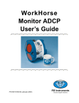
Download The RDI Broadband ADCP and Transect User Notes for Logging
Transcript
14 July 1998
CSIRO Division of Marine Research
RV Southern Surveyor Data Collection System
The RDI Broadband ADCP and
Transect User Notes
for Logging Data on a PC
Pamela Brodie & Helen Beggs
CSIRO Division of Marine Research
Hobart, Tasmania, Australia
Version 1.01: July1998
©1998, CSIRO Division of Marine Research
Describes the Broadband ADCP installation on the RV Southern Surveyor
and setting up a PC for data acquisition using the RD Instruments software
Transect and associated RDI utilities.
SS0198 files and data from the Transect PC can be found gzipped on
/local3/crdata3/raw_data/ss9801_phc/newdata/ss2/pc_data/transect or on
exabyte tape backup of ss9801.
This document was created based on the template on fdcs /opt/fdcs/doc/FDCS_template. It is archived fdcs /opt/fdcs/doc/ssurv/transect.doc.
A PDF version of this document: transect.pdf requires Acrobat Reader 3.
See http://marine.csiro.au/datacentre/GIS_data/doc/transect.pdf
2
The RDI Broadband ADCP and Transect User Notes
Introduction
1.0 Introduction
This document describes the RD Instruments (RDI) Broadband Acoustic
Doppler Current Profiler (BBADCP). It outlines the installation of the
instrument on the RV Southern Surveyor in January 1998, and the configuration and PC setup used to log data using the RDI software Transect
2.80.
Material from the several available references is drawn together here so
that procedures which were used for the BBADCP setup are recorded in a
single document. A minefield of different versions of firmware, software
and documentation has been negotiated, although no doubt, not exhaustively.
The procedures described here would be repeated to check on the instrument on re-commission, after moonpool trolley installation or after it has
been returned from service or repair by the manufacturer. It is unlikely
that the same PC would be available on the Southern Surveyor for when
Transect is to be used after SS9802, so another PC would need to be configured. A quick outline of data acquisition procedures for using Transect
is found in Appendix 3.
The primary means of logging ADCP data on the Southern Surveyor is on
a Sun, with an extended version of the ADCP Logging System software
used for the Narrowband instruments on the RV Franklin and on RV
Aurora Australis. The code now also interprets the completely different
BBADCP command set. Refer to the The Southern Surveyor BBADCP
Logging System User Manual for details.
Transect is the RDI data collection program which is run on a PC. This
was used for initial testing of the BBADP and, if required, can serve as a
backup BBADCP logging system. The main purpose of this document is to
detail how Transect was set up and used, to note the problems which were
encountered and to provide a quick guide to running Transect for the user
with a suitably prepared PC.
The Ashtech ADU2 is a GPS-based 3 dimensional position and altitude
determination system. This was installed on the Southern Surveyor also
in late January 1998. As well as position data, the Ashtech logs heading,
pitch and roll data. These provide the important rotation corrections to
BBADCP measurements. For details of the installation, calibration and
configuration of the Ashtech refer to the SSDCS Ashtech ADU2 GPS
Installation and Configuration Notes.
The RDI Broadband ADCP and Transect User Notes
3
Introduction
4
The RDI Broadband ADCP and Transect User Notes
References
2.0 References
2.1
SSDCS Notes and Manuals
The Southern Surveyor BBADCP Logging System User Manual 1.0,
CSIRO, April 1998 [SSLS].
Ashtech ADU2 GPS Installation and Configuration Notes, CSIRO, April
1998 [AGIC].
2.2
RDI Documentation
The RDI BBADCP documentation which came with the instrument is
listed below.
•
[VMTM] Vessel Mount Technical Manual, April 1997 (Assumes Version 5.5x firmware). Version 5.52 firmware was supplied with the
instrument.
•
[UG] VM-BBADCP User’s Guide for Vessel-Mount Data Collection,
1996
•
[TUM] User’s Manual for the RD Instruments Transect Program (for
Use With Broadband ADCP), July 1994 (Incorporates Change 5). This
manual assumes the use of software version 2.70. NOTE:Version
2.80 Transect software was supplied with the instrument.
•
[PRIM] Principles of Operation: A Practical Primer, 1996
Essential reading for the latest RDI information, however, is on the RDI
web site. For full access to the important customer support sections of this
site user is registration with RDI is required.This can be done within a
couple of business days by entering the required details at http://www.rdinstruments.com/forms/registration/rdiwebreg.html
For urgent access to the RDI site the registration form must be completed
before a call is made to RDI to hurry the process along Bob Mains
[email protected]
(+1) 619-693-1178
RDI News, the RD Instruments Electronic Newsletter, is emailed to subscribers. It contains notices of courses, events, notification of updates to
Field Service Bulletins, application notes, technical papers, upgrade
notices, documentation and FAQs.
To “subscribe” to the newsletter:
MAILTO:[email protected]
SUBJECT: subscribe
MESSAGE: Your name, organization, e-mail and postal addresses,
telephone and fax numbers, ADCP system type.
The RDI Broadband ADCP and Transect User Notes
5
References
To "unsubscribe" (or to remove duplicate mailings):
MAILTO:[email protected]
SUBJECT: unsubscribe
2.3
Red Folder
Print-outs of useful items from this site and correspondence with RDI
Customer Service are found with other documents of interest in the Red
BBADCP Folder [RB] -
2.4
•
[FAQ] Broadband Frequently Asked Questions
•
[FSA] Field Service Application Notes
•
[FSD] Field Service Documents
•
[email] Correspondence through email with RDI Support
•
[corr] Correspondence with Nils Oien of NIWA and others
Floppy Disk
A floppy disk containing the following files is in the Red Folder.
6
•
ss.cfg
•
ssnav.nav
•
External.dat
•
asciidate.awk
•
notes.txt
The RDI Broadband ADCP and Transect User Notes
The Instrument
3.0 The Instrument
The RDI Broadband ADCP is a 150kHz High Power module instrument
with a four beam transducer, a beam angle of 20 degrees, and concave configuration. The firmware is Version 5.52.
The BBADCP Configuration Summary can be found in Appendix 1.
Vessel-mounted ADCPs used on DMR’s RV Franklin and on the Antarctic
Division RV Aurora Australis have hitherto been Narrowband instruments. The BBADCP was purchased because of the lack of availability
from RDI of another Narrowband ADCP within the required time frame.
There are major differences between Broadband and Narrowband
ADCPs. The Narrowband ADCP is an older design with many hardware
settings whereas the BBADCP is more easily maintained, having an
emphasis on firmware settings.
The profiling range of the BBADCP is lower than the older NBADCP.
Range is sacrificed in favour of greater single ping accuracy, allowing
higher accuracy in shorter averaging times. RDI notes that on a moving
platform this may be an advantage as longer averaging times of Narrowband instruments result in less spatial resolution.
It is conceded however that on some vessel mounted applications profiling
range is considered of paramount importance. RDI claims that with certain settings, the BBADCP can obtain 90-95% of the NBADCP range
(FAQ24). If so, no doubt this would be in very favourable sea conditions.
Such settings certainly impose constraints on ship speed. The range on a
BBADCP is increased by narrowing the bandwidth which increases the
signal to noise ratio. Use of the narrowest bandwidth setting (WM1,WB2),
however, is not recommended by RDI (email from rdifs 23/03/1998).
A Broadband ADCP scales bin (depth cell) sizes based on the true beam
angle of the transducer, whereas the Narrowband depth cells are selected.
Speed of sound calculations are possible with the BBADCP whereas the
Narrowband always uses a constant speed of sound.
The instrument was shipped with a temperature sensor which can be
used for salinity calculations. It has an accuracy of +/-0.5 [VMTM B-6].
There is also a synchro sensor which was used for the gyrocompass. Heading input from the ADU2 GPS is normally used for logging, but the gyro
provides a backup data stream.
The system is also capable of external triggering so the BBADCP and, for
example, the EK500 and/or the bridge echo sounder can function without
mutual interference.
3.1
Factory Default Settings
Factory default settings were examined by resetting the instrument to
factory defaults, and then interrogating the BBADCP using the RDI utility BBTALK. See section 4.2 for descriptions of BBADCP command
groups and short notes on how to query settings on the instrument.
The RDI Broadband ADCP and Transect User Notes
7
The Instrument
The settings were compared with those documented for 150kHz instruments running firmware V5.5x or later [VMTM c-5 Table C-2]. These differences were found Documented default
BC245
BG25
WG25
nil
nil
Factory default
BC220
BG80,30,00030 *
WG0
BB0000 *
BH190,010,004,040 *
* The BG factory default setting on our instrument was queried. Also
there was no documentation for two Bottom Track settings. RDI were
notified of the BB and BH values. The function and effects of these
defaults was queried . Also details on the four undocumented SVSS sensor commands (DW,DX, DY,DZ) were requested (email 01/04/98). The
response from RDI follows.
3.2
RDI Email Supplementary Documentation
An email from RDI’s Darryl Symmonds 10/04/98 contained the following
notes on BBADCP documentation.
BB - Bottom Track Blank Interval. This command works exactly like the
WF command does. The only difference it is a blanking period for the bottom track measurement. The water profile blanking (WF) command is
not used by the bottom track. Therefore, it is possible for the bottom track
to sometimes lock onto a false bottom. This really only happens when the
ADCP is being used towards the end of its bottom track range. Say the
last 85% of bottom track range. At this time, it has been seen for the
ADCP to lock in on the ringing that occurs in the first few meters of the
profiling range. The BB command can eliminate this false detection.
BG and BH - These commands have been developed for certain shallow
water bottom tracking thresholds. N/A stands for not/applicable. These
commands are used for Bottom Mode 6. Bottom Mode 6 is intended for
shallow river work and is a proto-type mode. Please just ignore these
commands.
As for Jim Rogers recommendations on the BG command this was a small
mistake. He confused the BG command for the WG command. The WG
command stands for the water profile percent good threshold. Jim mistakenly assumed that the BG command would have the same meaning.
He apologises for the confusion this caused.
D commands in general had all been added for a special speed of sound
sensor. This sensor is a non-standard piece of equipment that is only for 3
customers in the world. The commands really should not be visable
within the system, but are. Since these commands are for a very select
group of users, RDI does not document them.
8
The RDI Broadband ADCP and Transect User Notes
The Instrument
3.3
Care with Settings
RDI warns that the ADCP is a complex instrument and suggests caution
in any departure from Factory-set values.With due consideration, changes
could be made to the Factory Default settings of the BBADCP and saved
as User Default Settings (see Appendix 5).
For logging data on RV Southern Surveyor, both on the Sun and on a PC
running Transect, it was decidedexplicit configuration is preferable and
that User Default settings would not normally be used.
The RDI Broadband ADCP and Transect User Notes
9
The Instrument
10
The RDI Broadband ADCP and Transect User Notes
Installation
4.0 Installation
The BBADCP was successfully bench-tested after delivery in late January
1998.
4.1
Transducer
4.1.1
Location
In January 1998 the ADCP transducer was installed on an adjustable pod
in the moonpool of the Southern Surveyor by divers. The draft of the
Southern Surveyor is 5.5m, LOA is 66m.The transducer on the pod was
located at the aft end of the moonpool, 28.5m from the stern of the ship. It
was measured at dry dock to be 1.3m starboard of the centreline of the
ship. The aft end of the moonpool is 19.5m forward of the reference
antenna of the Ashtech GPS, which is 11.5m above the waterline.
The transducer can be lowered more than 1m below the hull of the Southern Surveyor. Adjustment of the pod may alter the alignment of the transducer. This would need to be measured after each adjustment with a
calibration using bottom track data.
For SS9801 the transducer was 0.5m below the hull, a transducer depth of
5.5m.
On SS9802 the pod was lowered to 1.5m below the hull, a transducer
depth of 6.5m.
A new transducer installation on a trolley is planned for the moonpool
before the BBADCP is next used. This would be late 1998 or early 1999. A
new installation should be followed by sea trials of the instrument. Adequate time should be allowed for data acquisition within bottom track
range for calibration purposes, using the Sun system.
4.1.2
Calibration and Misalignment
On installation of the transducer there was a reported misalignment of
45˚. This refers to the angle of the reference beam, which is beam number
3, with respect to the fore-aft axis of the ship. In dry-dock 4-8/04/98 measurements were taken of the position of the transducer before the pod
assembly, and with it the BBADCP transducer, was removed. The transducer was -13.89˚ from the intended 45˚ alignment.
Currently calibration for transducer alignment is done on the Sun.
On SS9801 a calibration was performed which resulted in a misalignment
value of 30.26˚. This value corroborates the physical measurements performed in dry-dock of the transducer being 31.11˚ from the centreline of
the ship.
The result of the calibration for SS9802 was that there was no significant
change in the transducer misalignment angle.
The RDI Broadband ADCP and Transect User Notes
11
Installation
4.2
BBADCP Commands
The command set for the BBADCP are described in the invaluable VMTM
Appendix C. There are command groupings of which it is helpful to be
aware.
First Letter
B
C
D
E
P
S
T
W
Command Group
Bottom-track
Control system
SVP-16 sensors
Environmental sensors
Performance and testing
Speed log
Timing
Water-track commands
BBADCP commands can be sent to the instrument and settings can be
queried using a Telnet, Terminal or Bbtalk session to connect to the
instrument. A general query using the first letter of a command group followed by a question mark can be useful. For example to view the bottom
track command setting type ‘B?’.
Sending the ADCP the string of a two upper-case letter command followed
by a question mark will invoke the response which displays the setting.
For example the response to ‘BA?’ would be’ BA = 20’.
The post SS9802 settings for the BBADCP were queried in this way. The
result, in Appendix 5, is a useful record of the commands with descriptions, ranges and units for Firmware Version 5.52.
4.3
Set-up of the Instrument and Default Settings
The BBADCP comes with a set of Factory Default commands. These are
stored in ROM. The most recent set of commands used are stored in battery backed RAM. The ADCP will retain the configuration in RAM unless
a CR command is issued, or the backup power is lost.
The command CR1 loads the Factory Default settings into RAM.
The command CR0 loads into RAM User Default settings: the commands
last stored in non-volatile memory using the CK command. If this is to be
used see Appendix 5.
When the ADCP is logging and commands are to be issued to it, a Break
signal is normally used. This interrupts ADCP processing, initializes the
system and sends a ADCP Version message. The ADCP is ready for input.
The Break signal does not erase any settings or data [VMTM C-9].
4.3.1
The ADCP Clock
The BBADCP has an internal real-time clock, and it is advisable that this
time be set to UT. When using Transect for logging data the time should
be checked, as the software uses this clock for the date/time stamp on
Acquire screens, on Playback displays, in the logged raw and processed
data, and in the ASCII-Out data files.
12
The RDI Broadband ADCP and Transect User Notes
Installation
4.3.2
Baud Rate
On advice from RDI the baud rate of the BBADCP was set for efficient
data flow to 38400. It was increased from the default 9600 to 38400 using
RDI software Bbtalk in the following a procedure which is outlined in
RDI FAQ10. The process would need to be repeated in such instances as
that on 14 February 1998 when the instrument appeared not to be talking. An inexplicable glitch had reset the ADCP to 9600 baud.
•
connect the ADCP to the PC and switch the instrument on
•
run Bbtalk (probably from the c:\rdi directory of the PC)
•
send a Break signal with the <End> key
•
with the command CR0 retrieve User Parameters and check them
•
enter the command ‘CB611’ (to select the 38400 baud rate using no
parity and one stop bit)
•
press the <F5> function key which opens BBTALK port setup window
and change the comms port setting to 38400
•
<F6> saves configuration
•
press <Esc> to exit the setup window
•
send the command ‘CK’ to save the new baud rate setting as user
default
•
the command ‘CB?’ should confirm CB is 611
•
<Alt>X closes Bbtalk. The ADCP is now ready to use the new baud
rate. The baud rate will reportedly stay at this until you change it
with the CB command or press the reset button on the CPU board.
NOTE: Fortunately the CR1 command will not change this baud rate setting to the factory default value stored in ROM.
4.3.3
Battery Sleep Mode
During initial testing an annoying factory default setting caused problems. The ADCP placed itself into sleep mode when a ping (CS) command
had not been sent. It was necessary to issue the CL0 command to stop this
battery saver mode. CL0 was saved as a User Default and used in configuration files. The the factory default setting is CL1.
4.3.4
External sync and Acoustic Interference
To avoid interference with other acoustic devices the BBADCP can synchronise pings with an external trigger. If the ADCP cannot be master,
the preferred setting is CX2 where the ADCP triggers on a low to high
transition.
The omni-directional fish detection sonar used on SS9801 did interfere
with ADCP data gathered on that cruise. There was no opportunity to systematically test when or why this occurred
4.3.5
Setting the Time Per Ensemble
It was found that on our instrument the TE command required the format
‘TEhh:mm:ss.ff’. The documented format ‘TEhhmmssff’ was not accepted
The RDI Broadband ADCP and Transect User Notes
13
Installation
as input by the instrument [VMTM C-5]. RDI were notified [email
27/02/98].
4.3.6
Gyro
On powering the deck unit procedures for setting up the gyro should be
observed if it is to be used as backup for the heading data stream from the
Ashtech. Refer to the documentation SSLS.
4.4
Testing the BBADCP
4.4.1
Instrument Test
A preliminary comms test was performed with Bbtalk or another terminal emulator. Send a Break signal to the ADCP (press the <End> key).
The response should be the display of a wake-up message. The PI command will run built in tests of the BBADCP, and the results of these four
tests will be displayed [VMTM 1-6].
Bbtest can be run from a PC [VMTM 5-3]. The log file resulting from running RDI software Bbtest is in Appendix 2.
4.4.2
Leg 1 of SS0198
Voyage 1 was the opportunity to test the BBADCP, logging data with both
Transect and Sun software. It was necessary to become familiar with the
new BB commands and set up suitable configurations.
Many short acquisitions were made in an attempt to estimate transducer
misalignment. However the results were inconclusive until calibration
software was run from bottom track data collected on the Sun.
The range of the BBADCP in various profiling modes was tested. Maximum range of about 320m was obtained. This was in calm conditions
when the ship was stationary.
4.4.3
Data logged
The data logged with Transect were for testing purposes so otherwise are
of no particular interest. They can be found on the exabyte tape backup of
SS9801. There are 140 raw data files, 149 processed data files and 118
navigation data files.
The ADCP date and time was incorrect throughout SS0198. The year was
‘0’ and is changed to ‘98’. To convert the time to UT it is necessary to subtract 21 minutes and to subtract 36 seconds from the time. There is an
ascdate.awk script which can be used to fix the date/time of a Transect
ascii-out file with a single command line (where ‘y m d’ would be the date
to be fixed eg. ‘0 2 12’).
awk -f ascdate.awk infilename|grep -v ‘y m d’ > outfilename
Transect off West Coast of Tasmania
Although the BBADCP was in the initial stages of testing there was an
attempt made to gather data for David Griffin along one transect off the
west coast of Tasmania on 11/02/98.
14
The RDI Broadband ADCP and Transect User Notes
Installation
Because for this voyage the PC did not have the required comms ports for
logging both Nav and heading data, logging was only performed within
bottom track range with heading input from the Ashtech ADU2. The raw
data file was re-run with in Playback with a configuration file applying
the transducer misalignment of 30.26. Good heading data was available
for only the first 26 minutes. It was found later that the Ashtech data
stream to the Transect PC had not been up-dated from 22:03:51. The GPA
files were not logged on the Sun from 22:00, so it is possible that the Ashtech data stream was stopped during Sun software testing.
Due to time constraints the requested second transect was not attempted.
The RDI Broadband ADCP and Transect User Notes
15
Installation
16
The RDI Broadband ADCP and Transect User Notes
Transect
5.0 Transect
Transect software Version 2.80 was used to test the instrument settings
and acquire data. Note that the documentation, the User’s Manual [TUM]
assumes that you are using software version 2.70. Transect 2.85 was
released in June 1998 and down-loaded from the RDI web site. The only
change is a new Playback module fix.
The Transect user interface draws together several program modules to
communicate with and configure the ADCP, to collect and display data, as
well as to play-back or re-process the data.
Transect has satisfied users, but there are major limitations, especially
for vessel mounted BBADCPs where navigation and attitude readings are
required and large amounts of data are gathered.
5.1
•
As at July 1998 Transect will still not run on fast microprocessers,
such as a Pentium II. The message ‘PC runtime error 200’ is received.
Don’t up-grade your pc in a hurry!
•
Backup: Transect is reliably run only in DOS mode on the PC. To back
up the data, acquisition has to stop. This can be quite an interruption
to logging as typically there are many large files to archive.
•
Reliability of Settings: Although the user may elect to use a particular
configuration file, that file will be up-dated by Transect. Indeed the
list of direct commands may be truncated, with potentially unreliable
results.
•
Stability and memory problems: The software will crash, for example,
if there are too many files in a directory Transect is accessing.
•
A Transect software crash may corrupt your configuration file, so
always run with a copy of the file.
•
Rigid data stream inputs: a 3D GPS can feed all the data required for
navigation and attitude in a single stream. These data must nevertheless be sent through two separate comms ports on the PC.
•
Rigid data formats: To fully utilise some attitude readings (pitch and
roll) which are in this single data stream from the 3D GPS, a second
PC would be required to re-format the string and feed it to the
Transect PC, as Transect will accept only pitch, roll and heading in
that order! All Ashtech ADU2 output streams which include these
fields are in the order heading, pitch, roll.
Configuration Files
Transect modules use an ASCII configuration file which contains settings
information. The user could use the Transect software to select settings,
creating or modifying a configuration file. However, in the first instance, it
is recommended the user edit an existing text configuration file outside
Transect and selection of options in Transect modules which will modify
this file be avoided.
The RDI Broadband ADCP and Transect User Notes
17
Transect
The user is prompted for the name of a configuration file on starting
Transect, or the formerly loaded file will be invoked at startup. Transect
displays show the options from that configuration file. To load another
configuration file use the <F3> key and enter the file name.
It is useful to note that in Acquire, Transect issues a stream of commands
to the ADCP before issuing the direct commands from the configuration
file [TUM H-2]. This is worth noting as, if they are used, User Default settings will not take effect in Transect unless ‘CR0’ is explicitly included in
the direct commands of the configuration file. The commands Transect
usually sends to the ADCP to place it in a known state are:
CR1
CF1110
EZ0111111
EX00000
TE00000000
TP000000
PD0
An outline of the Transect menu options follows. With the appropriate
configuration file there is little if any need to alter options using these
interfaces unless otherwise noted.
5.2
Communications Menu
Communications between Transect and external devices are set up or displayed here. Given a suitable configuration file (see the following section
6), a ‘.nav’ file created with Navcfg and an External.dat file, all that is
done in this menu is to confirm that an interrupt is set up in the Navigation menu to enable acquisition and processing of navigation data with
Navsoft.
For the Southern Surveyor setup COM1 connects to the ADCP, COM2 is
used for navigation and COM4 is used for an external sensor, in this case
heading (and, potentially, pitch and roll if the data stream was correctly
formatted).
Navigation is necessary for corrections for ship velocity to ADCP measurements when the ship is not within range of bottom tracking. The quality of data which is logged will improve when differential corrections can
be applied to GPS data.
Heading is also required to rotate ADCP measurements into earth referenced currents. Further corrections to measurements can be applied
using pitch and roll readings, if they are available.
The options for feeding navigation and attitude data streams into
Transect are extremely limited.
The Ashtech ADU2 GPS is the single source of the data streams of interest - the NMEA sentences VTG and PAT. However, incredibly, attitude
and navigation sentences must be fed into separate comms ports on the
PC which is to be used to run Transect. At least three comms ports are
18
The RDI Broadband ADCP and Transect User Notes
Transect
thus required, the ADCP uses one port, the second port receives navigation data. The third port is necessary for attitude. Only the heading data
can currently be used by Transect as pitch and roll readings appear in the
wrong order in the data stream.
Installation of the third serial comms card to the PC on the Southern Surveyor was not achieved until just before SS9802 departed. We used COM4
with the interrupt normally used for a printer - IRQ7 [FAQ12].
5.2.1
Navigation
A package called Navsoft decodes navigation data for Transect. For it to
function the configuration file should enable NAV communications and
have in the Recording section of the configuration file ‘Navigation (YES)’.
An initial setup is required using Navcfg to select the port parameters
and the data format expected in the input NMEA string [TUM N-7]. The
software saves the results of this configuration session to a file, eg.
ss01.nav. This need only be done once for a given port and NMEA sentence, and the file can be invoked for any subsequent Transect session.
NOTE: A software interrupt is required for Navsoft to interface with
Transect while in Acquire mode. This is not done with the config file but is
specified (we used 242) in the Navigation screen of the Communications
menu.
5.2.2
External
External files are a means of feeding data from an external sensor into
Transect. They are documented in FAQ18 and FSB-089.
In this case the External.dat file was created to specify the format in
which Transect should read the NMEA $GPHDT heading string from the
Ashtech ADU2 GPS which is received in the EXTERNAL port nominated
in the Transect Communications menu and/or the configuration file.
This four line External.dat text file is as follows 1
$GPHDT
10
44
signifies data type 1: $xxHDT,hhh.hh@
NOTE: Ideally heading, pitch and roll also should be input to Transect
this way from the $GPPAT string, but format limitations require the
fields to be in the order: pitch, roll, heading. This could be achieved with
another PC receiving the Ashtech feed, re-formatting it and sending it to
the EXTERNAL comms port of the Transect PC.
5.3
Calibration Menu
The ADCP date and time, the transducer depth, and the transducer misalignment and other settings in the Calibration section of the configuration file can be checked in the Offsets and Scaling screens of this menu
[TUM Chapter 5].
The RDI Broadband ADCP and Transect User Notes
19
Transect
5.4
Planning Menu
In this menu the user can see or define where and how the data are to be
recorded. This corresponds to the Recording and Processing sections of
the configuration file. An Expert mode gives the user access to the contents of the Direct Commands section of the calibration file [TUM Chapter 6]. Care should be taken using this mode as unexpected changes may
be made by the Transect software to your configuration file!
5.5
Acquire Menu
On entry to this screen one is prompted to select the navigation configuration file which was created with Navcfg.
The next step in Acquire is for Transect to wake up the ADCP, and send it
the seven set commands used to put the instrument into a known state
(see section 5.1 above). The direct commands from the configuration file
are then sent to the ADCP.
Data logging is toggled on and off in this screen using the <F4> key. There
are various display options with which it is necessary to become familiar
[TUM Chapter 7].
The <F9> information screen is useful to check the current setup.
There is and option to toggle the display on the right of the screen
between navigation and bottom-track ship course information using the
<Alt> N key sequence.
5.6
Playback Menu
The Playback menu is for replaying raw or processed ADCP data files, or
to re-process the data in various ways [TUM Chapter 8].
5.6.1
Text Dump of Data Collected using Transect - ASCII-Out Function
The ASCII-Out function for output of data files is available in the Playback option of Transect. The raw or processed data of interest is selected
(use function key F8). The Alt-A key sequence will toggle ASCII Out.
Transect will prompt the user for a file name and a maximum file size
[TUM 8-2] .
The format of the ASCII Out data file is described in TUM A-4.
5.6.2
Error in Playback
In version 2.80 an error was introduced for the Broadband Transect program [FSB-112] which was fixed in Transect 2.85. This error in the Playback module typically caused an underestimation of the side-estimate
discharge calculations. The previously released version of this module
(v2.74) did not contain this error.
20
The RDI Broadband ADCP and Transect User Notes
Transect
A self-extracting executable file plbk274!.exe can be down-loaded from the
RDI website and run on the Transect PC. The resulting plbkmenu.exe,
dated 11/29/95 should replace the Transect version 2.80 file dated 7/24/96.
5.7
Other Settings
There are useful functions which can be invoked through DOS set commands which set Transect to save each configuration file with a similar
file name to the raw and processed data and nav files. To load those files
when playing back and to select which way the percent good is calculated
set AUTOSAVECFG=Y
set AUTOLOADCFG=Y
set USEPERCVEL=Y
These may be saved in the autoexec.bat file of the PC used for Transect.
However once again Transect is not very clever. With the AUTO options
enabled, Transect names the config files with the same extension of the
data and nav files (eg. ‘.000’ or ‘.005’). Transect is confised when you try to
manually load any of these AUTOSAVE config files, as it seems to want
only to look for config files with a ‘.cfg’ extension.
Even worse, care must be taken with AUTOLOADCFG enabled. When
replaying data which has been logged without recording the config file,
Transect will report it has loaded that data, and display the name of a fictitious config file. For example, Playback of ss01001r.000 will display
ss01001c.000 as the config file. That file does not exist and there is no
indication of whichconfig file Transect is, in fact, using!
The RDI Broadband ADCP and Transect User Notes
21
Transect
22
The RDI Broadband ADCP and Transect User Notes
The Configuration File
6.0 The Configuration File
6.1
Configuration File Used on SS9802
The Transect configuration files formats are described in TUM Appendix
C. Below is the config file for the SS9802. The headers and section delimiters in the file are in bold. They should not be edited!
BEGIN RDI CONFIGURATION FILE
COMMUNICATIONS
{
ADCP
( ON COM1 38400 N 8 1 ) [ Port Baud Parity Databits Stopbits ]
ENSOUT
( OFF COM2 9600 N 8 1 ) [ Port Baud Parity Databits Stopbits ]
NAV
( ON COM2 9600 N 8 1 ) [ Port Baud Parity Databits Stopbits ]
REFOUT
( OFF COM4 4800 N 8 2 ) [ Port Baud Parity Databits Stopbits ]
EXTERNAL ( ON COM4 9600 N 8 1 ) [ Port Baud Parity Databits Stopbits ]
}
ENSEMBLE OUT
{
ENS CHOICE ( Y Y Y Y N N N N ) [ Vel Corr Int %Gd Status Leader BTrack Nav ]
ENS OPTIONS ( NONE 1 8 1 8 ) [ Ref First Last Start End ]
ENS TYPE ( RAW ) [ RAW (default) or AVERAGED data transmitted ]
}
ADCP HARDWARE
{
Firmware
( 5.52 )
Angle
(
20 )
Frequency
( 150 )
System
( EARTH )
Mode
(
1)
Orientation ( DOWN )
Pattern
( CONCAVE )
}
DIRECT COMMANDS
{
BA030
BC220
BD000
BE5000
BF0
BM5
BP001
BX4000
CX0
EC1500
EX11000
TP000000
WB0
WD111100000
WF400
WL000010
WM1
WN050
WP00001
The RDI Broadband ADCP and Transect User Notes
23
The Configuration File
WS800
WV425
}
RECORDING
{
Deployment ( SS0298 )
Drive 1 ( C )
Drive 2 ( C )
ADCP
( YES )
Average ( YES )
Navigation ( YES )
}
CALIBRATION
{
ADCP depth
( 5.50 m
)
Heading / Magnetic offset ( 0.00
0.00 deg )
Transducer misalignment ( 30.26 )
Intensity scale
( 0.43 dB/cts )
Absorption
( 0.039 dB/m )
Salinity
( 35.0 ppt )
Speed of sound correction ( NO -1.0 )
Pitch & roll compensation (
NO
)
Tilt Misalignment
( 0.00 deg )
Pitch_Offset
( 0.000 deg )
Roll_Offset
( 0.000 deg )
Top discharge estimate ( CONSTANT )
Bottom discharge estimate ( CONSTANT )
Power curve exponent
(
0.1667 )
Edge_slope coefficient ( -1.00000 ) [-1=Trianglar(0.3535):-2=Square(0.91):User]
}
PROCESSING
{
Average every ( 180.00 s )
Depth sounder ( NO )
MaxFileSize ( 1200 )
Refout_info ( 1 8 30.00 1.000 0 1) [bins:1st last, limit, weight, format, delaysec]
External_formats ( Y N N N N ) [ HDT HDG RDID RDIE ]
External_decode ( Y N N N ) [ heading pitch roll temp ]
Start_Shore_distance ( -1 ) [ cm ]
End_Shore_distance ( -1 ) [ cm ]
Edge_distance_prompt ( NO )
}
GRAPHICS
{
Units
( SI )
Velocity Reference ( EARTH )
East_Velocity
( -100.0 100.0 cm/s )
North_Velocity ( -100.0 100.0 cm/s )
Vert_Velocity
( -100.0 100.0 cm/s )
Error_Velocity ( -100.0 100.0 cm/s )
Depth
(
1 40 bin )
Intensity
( 40 150 dB)
Discharge
( -1000 1000 m3/s )
East_Track
( -100 1000 m )
North_Track
( -3050 400 m )
24
The RDI Broadband ADCP and Transect User Notes
The Configuration File
Ship track
( 5 bin 50.0 cm/s )
Proj_Velocity
( -100.0 100.0 cm/s )
Proj_Angle
( 0.0 deg from N )
Bad_Below_Bottom ( NO )
Line1
(
Line2
(
}
)
)
HISTORY
{
SOFTWARE
( BB-TRANSECT )
Version
( 2.80 )
}
END RDI CONFIGURATION FILE
6.2
RDI Recommendations for Configuration
Water-profiling modes are described in an RDI Application Note [FAS003]
dated to apply January 1 1997.
If using modes other than WM1 WB0 must be used (RDI email 22/03/98).
Using WM1 the Mode 1 Ambiguity Velocity (WV) is calculated WV = (Max ship speed + max expected current speed)*sin(beam angle)*1.5
= 369 cm/s in our case.
For Bottom-tracking RDI recommends you never change BC correlation
threshold default BC220 (Version 5.50 and later) [].
For water-tracking RDI recommends you never change WC064 Correlation Threshold default and suggests care in adjusting WE1000 Error
velocity turned off. WA ??[]
6.2.1
Bbsetup
The RDI Bbsetup software provides a testing ground for combinations of
some settings. It can indicate the standard deviations, profiling ranges
and timings which may result. I does not cover some recent Phase 3
BBADCP options. There is adequate on-line help.
The RDI Broadband ADCP and Transect User Notes
25
The Configuration File
26
The RDI Broadband ADCP and Transect User Notes
BBADCP Configuration Summary
Appendix 1
BBADCP Configuration Summary
Date:
1/5/98
Customer:
CSIRO
Job Number:
229036
System Type:
Vessel Mount
Frequency:
Configuration:
150 kHz
Concave
Serial Numbers Chassis:
Transducer:
137
2699
Firmware CPU:
XDC:
PWRTIMING:
Sync:
5.52
1.16
c5d3
1.01
Power Configuration Input Voltage Range:
Cable Length (meters):
High
20
Transducer Number of Beams:
Beam Angle (degrees):
4
20
Sensors Temperature
Synchro
Communications Serial (ASCII,8-bit):
Baud Rate:
Parity:
RS-232
9600
None
This is based on the sheet RDI Instruments Broadband Configuration Summary which was
shipped with the instrument.
The RDI Broadband ADCP and Transect User Notes
27
BBADCP Configuration Summary
28
The RDI Broadband ADCP and Transect User Notes
BBADCP Test Results
Appendix 2
BBADCP Test Results
-------------------------------------------------------------------------BBTEST 1.20 1998/01/28 08:00:51.31
------------------------------------------------------------------------------------------------------- CONNECT TEST --------------------------------Wakeup message--~[
Broadband ADCP Version 5.52
RD Instruments (c) 1991-96
All rights reserved.
>
COM port : COM1
Baud rate : 9600
TEST OK
-------------------------------- INFO TEST ------------------------------Frequency: 153600 HZ
Configuration: 4 BEAM, JANUS
Match Layer: 10
Beam Angle: 20 DEGREES
Beam Pattern: CONCAVE
Orientation: DOWN
Xducer Ser #: 02699
Sensor(s): TEMPERATURE
XDC Firmware: 1.16
CPU Firmware: 5.52
DEMOD #1 Ver: ad46, Type: 3
DEMOD #2 Ver: ad46, Type: 3
PWRTIMG Ver: c5d3, Type: 4
TEST OK
----------------------------- BUILT IN TESTS -------------------------------PI test--[BEGIN Built In Tests]
CPU RAM Test ........... PASS
Realtime Clock Test .... PASS
Timing Card RAM Test ... PASS
Demod RAM Test ......... PASS PASS
[END Built in Tests]
---PT1 test--DAC/ADC Test Results = $0 ... PASS
---PT2 test--AMBTEMP = 26.1 Degrees C
VMVDD3 = 15.5 Volts
The RDI Broadband ADCP and Transect User Notes
29
BBADCP Test Results
VMVDD1 =
VMVDC =
5.0 Volts
24.3 Volts
---PT3 test--Correlation Magnitude:
Lag Bm1 Bm2 Bm3 Bm4
0 255 255 255 255
1 195 186 184 197
2 85 59 61 85
3 24 23 14 28
4 2 18 8 10
5 4 12 5 6
6 4 4 4 2
7 7 15 6 10
High Gain RSSI:
Low Gain RSSI:
53 51 51 51
18 13 13 13
Demod 1 DAC: 115 112 116 114, Duty:
Demod 2 DAC: 113 117 115 112, Duty:
49 51 50 49, LPF: 0
52 49 47 49, LPF: 0
Receive Test Results = $00000000 ... PASS
---PT4 test--IXMT =
3.3 Amps peak
VXMT = 253.5 Volts peak
Transmit Test Results = $00 ... PASS
---PT5 test--0 0 0 0
0 0 0 0
0 0 0 0
0 0 0 0
255 255 255 255
0 0 0 0
0 0 0 0
255 255 255 255
0 0 0 0
0 0 0 0
0 0 0 0
255 255 255 255
Electronics Test Results = $00000000 ... PASS
---PT6 test--Receive Bandwidth:
Sample
bw bw bw bw bw
rate expect Bm1 Bm2 Bm3 Bm4
154
39 43 46 46 42 Khz
results
PASS PASS PASS PASS
30
The RDI Broadband ADCP and Transect User Notes
BBADCP Test Results
---PT7 test--RSSI Time Constant:
RSSI Filter Strobe 1 = 38400 Hz
time Bm1 Bm2 Bm3 Bm4
msec cnts cnts cnts cnts
1 6 4 6 4
2 13 11 12 11
3 18 17 18 16
4 22 21 22 21
5 26 24 25 24
6 29 27 28 27
7 32 30 31 29
8 33 32 33 32
9 36 34 35 33
10 37 36 36 35
nom 48 45 47 45
result PASS PASS PASS PASS
TEST OK
The RDI Broadband ADCP and Transect User Notes
31
BBADCP Test Results
32
The RDI Broadband ADCP and Transect User Notes
Quick Guide to Data Acquisition
Appendix 3
3.1
Quick Guide to Data Acquisition
Transect - ADCP Data Acquisition
If required, the software package Transect can be used for logging but
also particularly for testing BBADCP data acquisition. There are useful
graphics, which can be re-displayed by playing back logged data.
Data acquisition using the configuration file SS0298.cfg includes navigation input from COM2 and heading input from COM4. The data stream
from Port B of the Ashtech 3D GPS is split between these two ports, and
contains the VTG, PAT and HDT NMEA sentences. These sentences normally are requested through the SSGPA Input Controller from the User
Interface of the Southern Surveyor Data Collection System. See the following Appendix 4 for information on directly requesting the required setting from the Ashtech ADU2.
3.1.1
Communication Options
Navigation input to Transect is configured in the RDI utility NAVCFG.
The relevant fields from the data stream are selected and saved in the file
SSNAV.NAV. An interrupt must be nominated to interface the Navsoft
programme with Transect for navigation to be logged.
Heading data is set up for Transect using a file which has been created
called EXTERNAL.DAT to select data, in this case, from the HDT string.
This is done from the External screen in the Transect Communications
option, based on the PRHT type.
3.1.2
The PC Autoexec File
For Transect Version 2.80 there are some DOS settings which can be used
to invoke useful features. These can be added to the autoexec.bat file of
the PC.
The configuration files used to log each data set will be saved and
replayed with the data using the following two commands set AUTOSAVECFG=Y
set AUTOLOADCFG=Y
The Percent Good quality calculation will be altered to be based upon the
number of good velocity values averaged together by Transect in a bin
using set USEPERCVEL=Y
3.1.3
Other Settings
Set the ADCP internal real time clock to UT with the command TSyy/dd/mm,hh:mm:ss
The RDI Broadband ADCP and Transect User Notes
33
Quick Guide to Data Acquisition
It is suggested that this time is checked for drift against UT in a week
(using ’TS?’ in BBTALK). This time will be used only for a time stamp in
Transect, notably seen on playback screens.
The Battery Saver Mode was set to ’CL0’, for no sleep between ensembles
or pings, in the User Default settings of the instrument.
3.1.4
Acquisition
In this mode with these settings the following steps will start acquisition:
34
•
Reboot the PC from Win95 into DOS mode
•
to get into the right directory on the c: drive type - cd\rdi
•
to run the program type - transect
•
From the menu selection go to "Acquire"
•
Select the SSNAV.NAV navigation setup file
•
Check that the SS0298.CFG configuration file is loaded. If not press
the F3 key and enter that file name.
•
Start logging by pressing the F4 key.
•
To stop logging toggle the F4 key.
•
You can remain in this screen until the next logging session. To exit
the screen press ALT X, and follow with an x. You are back in the
main menu and can quit the software pressing "q" and confirming
with a "y".
•
The data will be in a directory c:\SS02. This can be archived to the
SS2 directory /data/archive/pc_data/transect after copying the files to
/data/newdata/ss2/pc_data/transect. Mapping a network drive from
the PC to SS2 requires a netlogon which is done when typing ’exit’ to
return to Windows from DOS mode. At the logon opportunity use
username ’pcuser’ with password ’pcuser’.
•
It is recommended that changes to direct commands in the configuration file are made using DOS Edit. It is no slower, but more reliable
than using the ’Expert’ mode in the ADCP screen of the Planning
menu.
The RDI Broadband ADCP and Transect User Notes
Post SS9802 BBADCP Settings
Appendix 4
Post SS9802 BBADCP Settings
This is the result of the BBTALK logged session of command group queries of the BBADCP and settings and help on 31/03/1998.
>
Broadband ADCP Version 5.52
RD Instruments (c) 1991-96
All rights reserved.
>B?
BA = 020 ----------------- Evaluation Amplitude Min (1-255)
BB = 0000 ---------------- Blanking (cm) (0-9999)
BC = 220 ----------------- Correlation Magnitude Min (0-255)
BD = 100 ----------------- Delay Re-Acquire (# Ensembles)
BE = 5000 ---------------- Max Error Velocity (mm/s)
BF = 00000 --------------- Depth Guess (0=Auto, 1-65535 = dm)
BG = 80,30,00030 --------- N/A Shal Xmt (%), Deep Xmt (%), Deep (dm)
BH = 190,010,004,040 ----- N/A Thresh(cnt), S Amb(cm/s), L Amb(cm/s), MinAmb
BK = 0 ------------------- Layer Mode (0-Off, 1-On, 2-Lost, 3-No BT)
BL = 320,0640,0960 ------- Layer: Min Size (dm), Near (dm), Far (dm)
BM = 4 ------------------- Mode (4 = Default - Coherent, 5 = Default)
BP = 001 ----------------- Pings per Ensemble
BR = 0 ------------------- Range Resolution (0 = 4%, 1 = 2%, 2 = 1%)
BS ----------------------- Clear Distance Traveled
BX = 4000 ---------------- Maximum Depth (80-9999 dm)
BZ = 005 ----------------- Coherent Ambiguity Velocity (cm/s radial)
>C?
CB = 611 ----------------- Serial Port Control (Baud; Par; Stop)
CF = 10110 --------------- Flow Ctrl (EnsCyc;PngCyc;Binry;Ser;Rec)
CG = 0 ------------------- Ping Mode (0=Std, 1=Timed Data Out)
CK ----------------------- Keep Parameters as USER Defaults
CL = 0 ------------------- Battery Saver Mode (0=OFF, 1=ON)
CP = 255 ----------------- Xmt Power (0=min, 255=max)
CQ = 008 ----------------- Xmt Delay Select (0-127)
CR # --------------------- Retrieve Parameters (0 = USER, 1 = FACTORY)
CS ----------------------- Go (Start Pinging)
CT = 00 ------------------ Turnkey Mode (0=OFF,1=TURNKEY)
CX = 0 ------------------- Triggered Xmt (0=OFF,1=LH,2=HL,3=LH/HL,4=L,5=H)
CY = FFFFFEFF ------------ Clear BIT Log
CZ ----------------------- Power Down BBADCP
>D?
DA ----------------------- SVP-16 Atmospheric Pressure Correction
DI ----------------------- Identify the SVP-16
DQ ----------------------- SVP-16 Power On/Off Toggle
DS ----------------------- SVP-16 Sample/Display Data Scan
DW ## -------------------- SVSS Address Select (0-31)
DX ----------------------- SVSS Select Raw Data
DY ----------------------- SVSS Select Real Data
DZ ----------------------- SVSS Sample/Display Data Scan
>E?
EA = +00000 -------------- Heading Alignment (1/100 deg)
EB = +00000 -------------- Heading Bias (1/100 deg)
EC = 1500 ---------------- Speed Of Sound (m/s)
ED = 00000 --------------- Transducer Depth (0 - 65535 dm)
EH = 00000 --------------- Heading (1/100 deg)
EP = +0000 --------------- Tilt 1 Sensor (1/100 deg)
ER = +0000 --------------- Tilt 2 Sensor (1/100 deg)
ES = 35 ------------------ Salinity (0-40 pp thousand)
The RDI Broadband ADCP and Transect User Notes
35
Post SS9802 BBADCP Settings
ET = +2500 --------------- Temperature (1/100 deg Celsius)
EX = 00000 --------------- Coord Transform (Xform:Type; Tilts; 3Bm; Map)
EZ = 0020001 ------------- Sensor Source (C;D;H;P;R;S;T)
>P?
PA ----------------------- Pre-Deployment Tests
PC ### ------------------- Built In Tests, PC 0 = Help
PD = 00 ------------------ Data Stream Select (0-7)
PI = 011111 -------------- Built in Tests (Rpt;CPU;Clk;TC;DSP;Loop)
PM ----------------------- Distance Measure Facility
PS # --------------------- Show Sys Parms (0=Xdcr,1=FLdr,2=VLdr,3=Mat,4=Seq)
PT ### ------------------- Built In Tests, PT 0 = Help
>T?
TB = 00:00:00.00 --------- Time per Burst (hrs:min:sec.sec/100)
TC = 00000 --------------- Ensembles Per Burst (0-65535)
TE = 00:00:00.00 --------- Time per Ensemble (hrs:min:sec.sec/100)
TF = **/**/**,**:**:** --- Time of First Ping (yr/mon/day,hour:min:sec)
TP = 00:00.10 ------------ Time per Ping (min:sec.sec/100)
TS = 98/03/31,02:22:17 --- Time Set (yr/mon/day,hour:min:sec)
>W?
WA = 255 ----------------- False Target Threshold (Max) (0-255 counts)
WB = 0 ------------------- Mode 1 Bandwidth Control (0=Wid,1=Med,2=Nar)
WC = 064 ----------------- Low Correlation Threshold (0-255)
WD = 101 000 000 --------- Data Out (V;C;A PG;St;Vsum Vsum^2;#G;P0)
WE = 9999 ---------------- Error Velocity Threshold (0-5000 mm/s)
WF = 0400 ---------------- Blank After Transmit (cm)
WG = 000 ----------------- Percent Good Minimum (0-100%)
WH = 111 100 000 --------- Bm 5 Data Out (V;C;A PG;St;Vsum Vsum^2;#G;P0)
WI = 0 ------------------- Clip Data Past Bottom (0=OFF,1=ON)
WJ = 1 ------------------- Rcvr Gain Select (0=Low,1=High)
WL = 000,010 ------------- Water Reference Layer: Begin Cell (0=OFF), End Cell
WM = 1 ------------------- Profiling Mode (1-8)
WN = 050 ----------------- Number of depth cells (1-128)
WP = 00001 --------------- Pings per Ensemble (0-16384)
WQ = 0 ------------------- Sample Ambient Sound (0=OFF,1=ON)
WS = 0800 ---------------- Depth Cell Size (cm)
WT = 0000 ---------------- Transmit Length (cm) [0 = Bin Length]
WV = 425 ----------------- Mode 1 Ambiguity Velocity (cm/s radial)
WW = 004 ----------------- Mode 1 Pings before Mode 4 Re-acquire
WX = 999 ----------------- Mode 4 Ambiguity Velocity (cm/s radial)
WZ = 010 ----------------- Modes 5 and 8 Ambiguity Velocity (cm/s radial)
>
36
The RDI Broadband ADCP and Transect User Notes
BBADCP User Default Settings
Appendix 5
BBADCP User Default Settings
Normally on RV Southern Surveyor, configuration of the ADCP for logging with the Sun acquisition software and with Transect, explicit direct
commands are sent after loading the Factory Default settings into RAM
using the CR1 command.
To load the commands used by the Sun logging system there is a defaults
file bbadcp.cfg.defaults which can be loaded. Changes to logging parameters are be made with the BBADCP Menu in the User Interface strictly in
accordance with the directions in the SSLS User Manual [particularly
Chapters 2 and 4].
However, if required, certain BBADCP settings could be saved as User
Defaults to non volatile memory, which can then be loaded into the instrument at any time with the command CR0.
Setting up User Defaults is done using a terminal emulator or Bbtalk.
Note that the CB command for Serial Port Control is a special case and
done separately (see 4.3.2).
•
To set up User Defaults for the BBADCP establish a Telnet session to
the instrument from the Sun, or connect the ADCP to a PC running a
Terminal session or RDI Bbtalk software. Make sure the ADCP is
turned on.
•
Send a Break signal to the ADCP with the <End> key
•
If you wish to add to the already saved user default settings enter
CR0. Adding commands this way should only be done when you are
assured of which settings have been saved. If you wish to start afresh
enter the CR1 command.
•
Enter the commands you wish to be saved.
•
Issue the CK command to save these settings to non-volatile memory.
•
You can query the settings which have been changed to ensure they
are set as required. See section 4.2 above.
•
Exit the Telnet, Terminal or Bbtalk session.
The RDI Broadband ADCP and Transect User Notes
37


