1
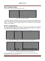
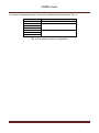
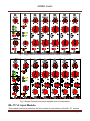
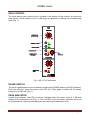
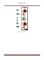
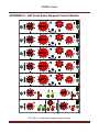
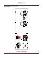
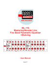
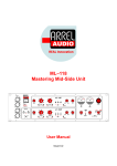
ML–117 Mastering Monster Line Five Band Modular Parametric Equalizer + Shelving User Manual Issue 0.1 ARREL Audio SAFETY INSTRUCTIONS WARNING Always follow the precautions listed below to avoid any possibility of serious injury or even death from electrical shock, shortcircuiting, damages, fire or other hazards. These precautions include, but are not limited to, the following: Do not expose the instrument to liquids and rain. Do not use it near water or in damp or wet conditions, or place containers on it containing liquids. If any liquid seeps turn off the power and unplug the power cord from the AC outlet. Do not put burning items, such as candles, on the unit. A burning item may fall over and cause a fire. This instrument contains no user-serviceable parts. Do not open the instrument or attempt to disassemble or modify the internal circuit. Never insert or remove an electric plug with wet hands. Check the electric plug periodically and remove any dirt or dust which may have accumulated on it. Do not place the power cord near heat sources such as heaters or radiators, and do not excessively bend or otherwise damage the cord, place heavy objects on it, or place it in a position where anyone could walk on, trip over, or roll anything over it. CAUTION Always follow the precautions listed below to avoid any possibility of serious injury or even death from electrical shock, shortcircuiting, damages, fire or other hazards. These precautions include, but are not limited to, the following: Do not connect the instrument to an electrical outlet using a multiple-connector. Doing so can result in lower sound quality, or possibly cause overheating in the outlet itself. When removing the electric plug from the instrument or an outlet, hold the plug itself and not the cord. Pulling by the cord can damage it. Remove the electric plug from the outlet when the instrument is not to be used for extended periods of time, or during electrical storms. Do not place the instrument in an unstable position where it might accidentally fall over. Before moving the instrument, remove all connected cables. When setting up the product, make sure that the AC outlet you are using is easily accessible. If some trouble or malfunction occurs, immediately turn off the power switch and disconnect the plug from the outlet. Even when the power switch is turned off, electricity is still flowing to the product at the minimum level. When you are not using the product for a long time, make sure to unplug the power cord from the wall AC outlet. Use only the stand/rack specified for the instrument. When attaching the stand or rack, use the provided screws only. Failure to do so could cause damage to the internal components or result in the instrument falling over. Information for Users on Collection and Disposal of Old Equipment This special symbol on the products, packaging, and/or accompanying documents means that used electrical and electronic products should not be mixed with general household waste. For proper treatment, recovery and recycling of old products, please take them to applicable collection points, in accordance with your national legislation and the Directives 2002/96/EC. By disposing of these products correctly, you will help to save valuable resources and prevent any potential negative effects on human health and the environment which could otherwise arise from inappropriate waste handling. For more information about collection and recycling of old products, please contact your local municipality, your waste disposal service or the point of sale where you purchased the items. [For business users in the European Union] If you wish to discard electrical and electronic equipment, please contact your dealer or supplier for further information. [Information on Disposal in other Countries outside the European Union] This symbol is only valid in the European Union. If you wish to discard these items, please contact your local authorities or dealer and ask for the correct method of disposal. ML-117 User Manual, Issue 0.1 Page 2 ARREL Audio ARREL Audio Contacts ARREL Audio Via A. Mondadori, 7 00128 Rome – Italy Tel +39 06 506 2017 Fax: +39 06 5062017 Info: [email protected] Web: www.arrel-audio.com Support: http://www.arrel-audio.com/support ARREL Audio is continuously working to the improvement of its systems and related documentation. In any case, we reserve the right to change the specifications without notice but in respect to the current legislation. Disclaimer: The information contained in this manual has been carefully checked and we believed is accurate at the time of publication. In any case, we do not assume any responsibility for inaccuracies, errors or omissions nor any liability for any loss or damage resulting either directly or indirectly from use of the information contained in this manual. ML-117 User Manual, Issue 0.1 Page 3 ARREL Audio TABLE OF CONTENTS SAFETY INSTRUCTIONS ................................................................................................... 2 ARREL Audio Contacts ........................................................................................................ 3 INTRODUCTION ................................................................................................................. 6 Housing and Rack Mounting ............................................................................................ 7 ML-117 Modules Table ......................................................................................................... 8 ML-117 Configurations ......................................................................................................... 8 ML-117 A: Input Module ..................................................................................................... 10 Gain Control ................................................................................................................... 11 Phase switch .................................................................................................................. 11 Peak indicator ................................................................................................................ 11 OFF SWITCH ................................................................................................................. 12 ± 5 𝒅𝑩 switch ................................................................................................................. 12 LO-CUT subsonic filter switch ........................................................................................ 12 CUT OFF FREQUENCY ROTARY switch ...................................................................... 12 HI-CUT switch ................................................................................................................ 12 ML-117 BC: Shelving Module Continuous Controls ........................................................... 13 Emphasis/de-emphasis control knob (hi and low) .......................................................... 13 Shelf slope switch (hi and low) ....................................................................................... 13 ON SWITCH................................................................................................................... 14 ± 5 𝒅𝑩 switch ................................................................................................................. 14 ML-117 BS: Shelving Module Stepped Controls ................................................................ 15 Emphasis/de-emphasis control knob (hi and low) .......................................................... 15 Shelf slope switch (hi and low) ....................................................................................... 15 Eq shelving section: ON SWITCH .................................................................................. 16 ± 5 𝒅𝑩 switch ................................................................................................................. 16 ML-117 DC: Parametric Module Continuous Controls ....................................................... 17 Q control knob ................................................................................................................ 17 Emphasis/de-emphasis control knob.............................................................................. 17 Emphasis/de-emphasis control switch ........................................................................... 18 Frequency control knob .................................................................................................. 18 F x 2 switch .................................................................................................................... 18 ML-117-DS: Parametric Module Stepped Controls ............................................................ 19 Q control knob ................................................................................................................ 19 Emphasis/de-emphasis control knob.............................................................................. 19 Emphasis/de-emphasis control switch ........................................................................... 20 Frequency control knob .................................................................................................. 20 Frequency trim control knob ........................................................................................... 20 ML-117 D: Band Pass Module ........................................................................................... 21 Cut-off frequency control knob ....................................................................................... 21 Frequency Range switch ................................................................................................ 21 LO-CUT switch ............................................................................................................... 21 HI-CUT switch ................................................................................................................ 21 ML-117 Back Panel Controls and Operations .................................................................... 23 Power supply switch ....................................................................................................... 23 bal/umbal switch ............................................................................................................. 23 APPENDIX A: External connections .................................................................................. 24 ML-117 User Manual, Issue 0.1 Page 4 ARREL Audio APPENDIX B: Half Front Panel ......................................................................................... 25 APPENDIX C: Half Front Panel Stepped Control Module .................................................. 26 APPENDIX D: Front Panel................................................................................................. 27 APPENDIX E: Back Panel ................................................................................................. 28 TECHNICAL SPECIFICATIONS ........................................................................................ 29 ML-117 User Manual, Issue 0.1 Page 5 ARREL Audio INTRODUCTION The ARREL Audio Mastering Monster Modular EQ ML-117 is an advanced 2-channel modular equalizer built to meet the versatility demands of professional recording and mastering engineers. Special analog design techniques has been used to obtain a precise control of the sound structure down to the minimum details. Each channel of the ML-117 is equipped with 7 modules. Three families of modules are available: stepped control, continuous control modules and custom modules. The first module on the left of each channel must be an input module, the other modules can be chosen between continuous, stepped or custom modules (see the compatibility list in Tab. 4). The ML-117 features HI and LO cut filters and a 5 band parametric equalizer section + high and low shelving filters. This advanced set of tools for the manipulation of the frequency spectrum allow for unique filtering designs and for tuning of the structure of the sound down to the smallest detail. The ML-117 is based on Livio Argentini’s patented single-stage parallel parametric filters. This innovative phase coherent EQ design offers the lowest distortion/noise specifications, not available on similar units on the market. The equalizer architecture provides a ±6 dB rotary knob with center detect controlling the input level, a 50 KHz HI-cut filter and a subsonic filter with 6 selectable cut-off frequencies. The continuous parametric control module is a traditional parametric equalizers with Q, frequency and emphasis/de-emphasis rotary knobs. This unit has been designed for mastering applications where very precise settings are required. To this purpose, both the parametric and the shelving sections are equipped by a special function button (±5 dB button) that halves the emphasis/de-emphasis range for super fine-tunings. When this button is pressed, the pot’s entire 270° rotation is spread on a ±5 dB range (rather than the default ±10 dB range) permitting and easy manual recall without the use of stepped controls. The filtering section offers low and high shelving filters with 3 different shelving slopes selected by a switch. The emphasis/de-emphasis for the shelving section is controlled in the ±10 dB range by rotary knobs. A special button labeled “±5 dB” halves the emphasis/de-emphasis range for super fine-tunings. The Monster EQ can be equipped with 5 or 6 (in the case the shelving function is not used) single-stage fully parametric bands. The F x 2 switches are used to multiply by 2 the frequency bands. The stepped control modules (ML-117 -S) are characterized by rotary switches. The ML-117-BS has 11 positions for emphasis/de-emphasis control and a three positions toggle switch for the shelving slope. The ML-117 BS has 11 positions for the emphasis/deemphasis control and 6 positions for the selection of the frequency band. Moreover a fine trim continuous knob is used for super fine tuning of the frequency. In the ML-117 short lever toggle switches have been used to limit accidental operations. To obtain an outstanding audio quality, no servo amplifiers are used in the ML-117 so IT IS NOT POSSIBLE TO UNBALANCE THE LINE OUT OF THE ML-117. If you need an unbalanced connection for the line out there follow the instructions in APPENDIX A. Even though the ML-166 has been designed for professional mastering applications, it can be used in any high profile recording, broadcast or live applications. ML-117 User Manual, Issue 0.1 Page 6 ARREL Audio HOUSING AND RACK MOUNTING The ML-117 has been designed to be compliant with a 3U rack. No specific air Conditioning is required for the racks, provided that there is a free flow of air through the rack from front to back and the temperature is maintained in the operating range. Consequently the racks may be stacked. ML-117 User Manual, Issue 0.1 Page 7 ARREL Audio ML-117 Modules Table At present the modules available are listed in Tab. 1 MODULE NAME ML-117A ML-117 BC ML-117 DC ML-117 E ML-117 BS ML-117 DS MODULE FUNCTION Input module Shelving module continuous controls Parametric module continuous controls Band pass continuous controls Shelving module stepped controls Parametric module stepped controls Tab. 1 ML-117 Series modules Two different types are available, the continuous control version and the stepped control version. The input module and the band pass module are available only in the continuous version. On customer request custom modules can be produced with different filter frequency characteristics. ML-117 Configurations The typical standard configuration of the ML-117 is the same of the ML-116: two channels (A and B) each equipped with an input module and full parametric equalizers in continuous (Fig. 1 and Tab. 2) or stepped (Fig. 2 and Tab. 3) version. SLOT NUMBER 1 2 3 4 5 6 7 MODULE NAME ML-117 A ML-117 BC ML-117 DC ML-117 DC ML-117 DC ML-117 DC ML-117 DC FUNCTION Input module Shelving module continuous controls Parametric module continuous controls Parametric module continuous controls Parametric module continuous controls Parametric module continuous controls Parametric module continuous controls Tab. 2 ML-117 Equalizer continuous mode controls configuration SLOT NUMBER 1 2 3 4 5 6 7 MODULE NAME ML-117 A ML-117 BS ML-117 DS ML-117 DS ML-117 DS ML-117 DS ML-117 DS FUNCTION Input module Shelving module stepped controls Parametric module stepped controls Parametric module stepped controls Parametric module stepped controls Parametric module stepped controls Parametric module stepped controls Tab. 3 ML-117 Equalizer stepped mode controls configuration Custom configurations can be implemented. In any case the first slot must be always equipped with an input module ML-117 A. ML-117 User Manual, Issue 0.1 Page 8 ARREL Audio In custom configuration some rules must be observed as illustrated in Tab. 4. SLOT NUMBER 1 2 3 4 5 6 7 FUNCTION Only Input module Shelving or parametric modules Only parametric modules Tab. 4 Slot Position-modules compatibility ML-117 User Manual, Issue 0.1 Page 9 ARREL Audio Fig. 1 Single channel front panel continuous control configuration Fig. 2 Single channel front panel stepped control configuration ML-117 A: Input Module This module must be provided as the first module of each section of the ML-117 chassis. ML-117 User Manual, Issue 0.1 Page 10 ARREL Audio GAIN CONTROL The input section gain control knob is located in the bottom of the module. A continuous level control (center detect) in the ± 6 dB range is obtained by rotating the corresponding knob (Fig. 1). Fig. 1 ML-117 A Front panel PHASE SWITCH The input signal phase can be inverted by pressing the PHASE button (red LED indicator). Push the button to invert the phase (red LED on). Push again to switch off the phase inversion (red LED off) (Fig. 1). PEAK INDICATOR A peak level detector (red LED on) circuit indicates when the output level is -6 dB with respect to the saturation level (Fig. 1). The red LED on do not means saturation but must be interpreted as a warning indicating you are reaching the saturation level. ML-117 User Manual, Issue 0.1 Page 11 ARREL Audio OFF SWITCH The parametric section can be excluded by pressing the OFF button (red LED indicator). Push the button to exclude the parametric section (red LED on). Push again to switch on the parametric section of the equalizer (red LED off) (Fig. 1). ± 5 𝒅𝑩 SWITCH This button changes the range of the emphasis/de-emphasis continuous or stepped controls in the corresponding parametric modules (ML-117 DC, ML-117 DS). The range can be changed to ± 5 dB by pressing the ± 5 dB button (yellow LED indicator). Push the button to change to the ± 5 dB range (yellow LED on). Push again to switch off the ± 5 dB function obtaining ± 10 dB range (yellow LED off) (Fig. 1). LO-CUT SUBSONIC FILTER SWITCH The input signal can be filtered by a variable cut off frequency subsonic filter by pressing the LO CUT button (green LED indicator). Push the button to activate the subsonic filter (green LED on). Push again to deselect the subsonic filter (green LED off) (Fig. 1). CUT OFF FREQUENCY ROTARY SWITCH The cut off frequency of the subsonic filter can be changed by the rotary switch. Six possible frequencies are available (10, 15, 20, 25, 30, 40 Hz) (Fig. 1). HI-CUT SWITCH The input signal can be filtered by a low pass filter by pressing the HI CUT button (green LED indicator). Push the button to activate the HI pass filter (green LED on). Push again to deselect the HI CUT filter (green LED off) (Fig. 1). ML-117 User Manual, Issue 0.1 Page 12 ARREL Audio ML-117 BC: Shelving Module Continuous Controls The shelving equalizers are available in two different versions: continuous control version (ML-117 BC) and stepped version (ML-117 BS). In the two sections HI and LOW of the ML-117 BC shelving filters are provided. Each control described in this section is applicable to the two shelving filters (HI and LOW) (Fig. 2). Fig. 2 ML-117 BC module EMPHASIS/DE-EMPHASIS CONTROL KNOB (HI AND LOW) The emphasis/de-emphasis control in the ± 10 dB range is obtained by rotating the corresponding knob (Fig. 2) for the ML-117 BC. The range becomes ± 5 dB if the ± 5 dB function is on. SHELF SLOPE SWITCH (HI AND LOW) The slopes of the HI and LO shelving filters can be changed by using the toggle switch (Fig. 2). Three slopes are available. ML-117 User Manual, Issue 0.1 Page 13 ARREL Audio ON SWITCH The shelving section can be activated by pressing the ON button (green LED indicator). Push the button to activate the shelving section (green LED on). Push again to by-pass the shelving section of the equalizer (green LED off) (Fig. 2). ± 5 𝒅𝑩 SWITCH The range of the shelving section emphasis/de-emphasis knobs can be changed to the ± 5 dB range by pressing the ± 5 dB button (yellow LED indicator). Push the button to change to the ± 5 dB range (yellow LED on). Push again to switch off the ± 5 dB function (yellow LED off) (Fig. 2). ML-117 User Manual, Issue 0.1 Page 14 ARREL Audio ML-117 BS: Shelving Module Stepped Controls In the two sections HI and LOW of the ML-117 BS shelving filters are provided. Each control described in this section is applicable to the two shelving filters (HI and LOW) (Fig. 3). Fig. 3 ML-117 BS module EMPHASIS/DE-EMPHASIS CONTROL KNOB (HI AND LOW) The emphasis/de-emphasis control in the ± 10 dB range is obtained by by selecting the corresponding step for the ML-117 BS (each step correspond to 2 dB). The range becomes ± 5 dB if the ± 5 dB function is on. In this case each step of the rotary switch corresponds to 1 dB (Fig. 3). SHELF SLOPE SWITCH (HI AND LOW) The slopes of the HI and LO shelving filters can be changed by using the toggle switch (Fig. 3). Three slopes are available. ML-117 User Manual, Issue 0.1 Page 15 ARREL Audio EQ SHELVING SECTION: ON SWITCH The shelving section can be activated by pressing the ON button (green LED indicator). Push the button to activate the shelving section (green LED on). Push again to by-pass the shelving section of the equalizer (green LED off) (Fig. 3). ± 5 𝒅𝑩 SWITCH The range of the shelving section emphasis/de-emphasis knobs can be changed to the ± 5 dB range by pressing the ± 5 dB button (yellow LED indicator). Push the button to change to the ± 5 dB range (yellow LED on). Push again to switch off the ± 5 dB function (yellow LED off) (Fig. 2). ML-117 User Manual, Issue 0.1 Page 16 ARREL Audio ML-117 DC: Parametric Module Continuous Controls Each control described in this section is applicable to the five standard frequency bands (LO, MID LO, MID, MID HI, HI) and to custom modules. Q CONTROL KNOB The Q value is changed by rotating the corresponding knob (Fig. 4). EMPHASIS/DE-EMPHASIS CONTROL KNOB The emphasis/de-emphasis control in the ±10 dB range is obtained by rotating the corresponding knob (Fig. 4). The range becomes ± 5 dB if the ± 5 dB function is on (ML117 DC). This knob works as frequency boost if the corresponding (-)CUT-OFF-BOOST(+) switch is in the BOOST position (switch lever green illuminated). This knob works as frequency cut if the corresponding (-)CUT-OFF-BOOST(+) switch is in the CUT position (switch lever red illuminated). Fig. 4 ML-117 DC ML-117 User Manual, Issue 0.1 Page 17 ARREL Audio EMPHASIS/DE-EMPHASIS CONTROL SWITCH This is a lever illuminated toggle switch. Frequency boost is selected if the corresponding (-)CUT-OFF-BOOST(+) switch is in the (-) position (switch lever green illuminated). Frequency cut is obtained if the corresponding (-)CUT-OFF-BOOST(+) switch is in the + position (switch lever red illuminated). If the switch is not illuminated, the off function is selected so the emphasis/de-emphasis knob is not active. This function is important in order to avoid accidental operations Fig. FREQUENCY CONTROL KNOB Turn the frequency knob in order to select the required frequency value (Fig. 4 and Tab. 5). F X 2 SWITCH This button selects the F x 2 function. Push the button to activate the F x 2 function (red LED on). Push again to deselect the F x 2 function (red LED off) (Fig. 4). This function permits to obtain ten different frequency bands. FREQUENCY BAND LO MID LO MID MID HI HI CUSTOM ML-117 Dc FREQUENCY BANDS F X 2 OFF 20-60 Hz 80-240 Hz 300-800 Hz 1000-3000 Hz 4000-12000 Hz XX-XX Hz ML-117 Dc FREQUENCY BANDS F X 2 ON 40-120 Hz 160-480 Hz 600-1600 Hz 2000-6000 Hz 8000-24000 Hz XX-XX Hz Tab. 5 Frequency bands for the ML-117 DC ML-117 User Manual, Issue 0.1 Page 18 ARREL Audio ML-117-DS: Parametric Module Stepped Controls Each control described in this section is applicable to the five standard frequency bands (LO, MID LO, MID, MID HI, HI) and to custom modules. Q CONTROL KNOB The Q value is changed by selecting the step (12 steps available) in the stepped version (Fig. 5). EMPHASIS/DE-EMPHASIS CONTROL KNOB The emphasis/de-emphasis control in the ± 10 dB range is obtained by rotating the corresponding knob (Fig. 5). The range becomes ± 5 dB if the ± 5 dB function is on. For the ML-117 DS we have 1 dB step (± 5 dB function off) or 0.5 dB step (± 5 dB function on) (Fig. 5). This knob works as frequency boost if the corresponding (-)CUT- OFF-BOOST(+) switch is in the BOOST position (switch lever green illuminated). This knob works as frequency cut if the corresponding (-)CUT-OFF-BOOST(+) switch is in the CUT position (switch lever red illuminated). Fig. 5 ML-117 DS ML-117 User Manual, Issue 0.1 Page 19 ARREL Audio EMPHASIS/DE-EMPHASIS CONTROL SWITCH This is a lever illuminated toggle switch. Frequency boost is selected if the corresponding (-)CUT-OFF-BOOST(+) switch is in the (-) position (switch lever green illuminated). Frequency cut is obtained if the corresponding (-)CUT-OFF-BOOST(+) switch is in the + position (switch lever red illuminated). If the switch is not illuminated, the off function is selected so the emphasis/de-emphasis knob is not active. This function is important in order to avoid accidental operations Fig. 5. FREQUENCY CONTROL KNOB Select the desired step to change the frequency band (6 steps are available: 20, 28, 40, 55, 75, 100 Hz) (Fig. 5 and Tab. 6). FREQUENCY TRIM CONTROL KNOB Rotate the frequency trim knob to change the frequency band. A variation of ± 10 % is available on 270 degrees of knob rotation. FREQUENCY BAND LO MID LO MID MID HI HI CUSTOM ML-117 DS FREQUENCY BANDS F X 2 OFF 20-28-40-55-75-100 Hz 80-110-160-220-300-400 Hz 300-420-600-825-1125-1500 Hz 1000-1400-2000-2750-3750-5000 Hz 4000-5600-8000-11000-15000-20000 Hz XX-XX-XX-XX-XX-XX Hz Tab. 6 Frequency bands for the ML-117 DS ML-117 User Manual, Issue 0.1 Page 20 ARREL Audio ML-117 D: Band Pass Module The ML-117 D is a flexible filtering module that cha be used as HI pass (LO CUT on, HI CUT off), LO pass (LO CUT off, HI CUT on) or BAND PASS (LO CUT on, HI CUT on) filter. CUT-OFF FREQUENCY CONTROL KNOB Turn the frequency knob in order to select the required cut off frequency (Fig. 6 and Tab. 7 ) for the LO CUT and HI CUT sections. Two ranges are available depending on the frequency range switch. FREQUENCY RANGE SWITCH This switch selects two different frequency ranges for the LO CUT and HI CUT sections (Fig. 6 Tab. 7). LO-CUT SWITCH The input signal can be filtered by a HI pass filter by pressing the LO CUT button (green LED indicator). Push the button to activate the HI pass filter (green LED on). Push again to deselect the HI pass filter (green LED off) (Fig. 6). HI-CUT SWITCH The input signal can be filtered by a LO pass filter by pressing the HI CUT button (green LED indicator). Push the button to activate the HI pass filter (green LED on). Push again to deselect the HI pass filter (green LED off) (Fig. 6). LO CUT FILTER FREQUENCY RANGE FREQUENCY SELECTOR SWITCH=1/10 1-10 KHz FREQUENCY SELECTOR SWITCH=8/10 8-20 KHz HI CUT FILTER FREQUENCY RANGE FREQUENCY SELECTOR SWITCH=1/10 20-60 Hz FREQUENCY SELECTOR SWITCH=8/10 50-150 Hz Tab. 7 Frequency bands ML-117 E band pass filter module ML-117 User Manual, Issue 0.1 Page 21 ARREL Audio Fig. 6 ML-117 E ML-117 User Manual, Issue 0.1 Page 22 ARREL Audio ML-117 Back Panel Controls and Operations POWER SUPPLY SWITCH The ML-117 power-on switch is located in the left part of the back panel. The power on state is indicated by the illumination of the switch (Fig. 4). BAL/UMBAL SWITCH On the back panel of the ML116 each output is equipped with a Bal/Unbal switch (Fig. 4). Fig. 4 Back panel ML-117 User Manual, Issue 0.1 Page 23 ARREL Audio APPENDIX A: External connections FIG. 5 ML-117 external connections ML-117 User Manual, Issue 0.1 Page 24 ARREL Audio APPENDIX B: Half Front Panel FIG. 6 ML-117 half front panel continuous control module ML-117 User Manual, Issue 0.1 Page 25 ARREL Audio APPENDIX C: Half Front Panel Stepped Control Module FIG.7 ML-117 half panel stepped control module ML-117 User Manual, Issue 0.1 Page 26 ARREL Audio APPENDIX D: Front Panel FIG.7 ML-117 front Panel ML-117 User Manual, Issue 0.1 Page 27 ARREL Audio APPENDIX E: Back Panel FIG.8 ML-117 Back Panel ML-117 User Manual, Issue 0.1 Page 28 ARREL Audio TECHNICAL SPECIFICATIONS MS-117 A: INPUT MODULE Input Electronically balanced, Impedance > 10 KΩ Input Gain Range: ±6 dB rotary knob with center detect Phase Inversion Phase Reverse button (red LED) PARAMETRIC SECTION Equalizer Mute Mute button to deselect the parametric section (red LED) ±5 dB Button dB range switch (yellow LED) to change the range of the emphasis/deemphasis potentiometer Input Peak Meter BAND PASS FILTER LO-CUT filter 6 selectable cut-off frequencies sub sonic filter (10-15-20-25-30-40 Hz) 12 dB/Oct HI-CUT filter 50 KHz cut-off frequency 12 dB/Oct MS-117 BC SHELVING EQUALIZER MODULE CONTINUOUS CONTROLS HI SHELF ± 10 dB gain (± 5 dB gain with ± 5 dB button on) LO SHELF ± 10 dB gain (± 5 dB gain with ± 5 dB button on) SHELF SHAPE SWITCH 3 positions switch to selects the slope of the shelving filters By-Pass True bypass switch (green LED) ±5 dB Button dB range switch (yellow LED) to change the range of the shelving emphasis/de-emphasis potentiometer ML-117 BS SHELVING EQUALIZER MODULE STEPPED CONTROLS HI SHELF 11 steps rotary knob ± 10 dB gain 1 dB step (± 5 dB gain with ± 5 dB button on, 0.5 dB gain) LO SHELF 11 steps rotary knob ± 10 dB gain 1 dB step (± 5 dB gain with ± 5 dB button on, 0.5 dB gain) SHELF SHAPE SWITCH 3 positions switch to selects the slope of the shelving filters ON switch True bypass switch (green LED) ±5 dB Button dB range switch (yellow LED) to change the range of the shelving emphasis/de-emphasis potentiometer ML-117 User Manual, Issue 0.1 Page 29 ARREL Audio ML-117 DC PARAMETRIC EQUALIZER MODULE CONTINUOUS CONTROLS FREQUENCY BAND F X 2 OFF All the filters are bell shaped LO MID LO MID MID HI HI CUSTOM 20-60 Hz 80-240 Hz 300-800 Hz 1000-3000 Hz 4000-12000 Hz XX-XX XX-XX Hz FREQUENCY BANDS F X 2 ON All the filters are bell shaped LO MID LO MID MID HI HI CUSTOM 40-120 Hz 160-480 Hz 600-1600 Hz 2000-6000 Hz 8000-24000 Hz XX-XX Hz F X 2 Button switch to multiply by 2 the frequency range of the parametric filters(green LED) BOOST-OFF-CUT SWITCH 3 positions switch to select the function of the gain potentiometer (emphasisOFF-de-emphasis) Emphasis/de-emphasis knob Rotary control knob to set the emphasis/de-emphasis value Q Control Rotary control knob to set the Q value ML-117 DS PARAMETRIC EQUALIZER MODULE STEPPED CONTROLS FREQUENCY BANDS All the filters are bell shaped Six steps rotary switch LO MID LO MID MID HI HI CUSTOM 20-28-40-55-75-100 Hz 80-110-160-220-300-400 Hz 300-420-600-825-1125-1500 Hz 1000-1400-2000-2750-3750-5000 Hz 4000-5600-8000-11000-15000-20000 Hz XX-XX-XX-XX-XX-XX Hz Frequency trim switch to multiply by 2 the frequency range of the parametric filters(green LED) BOOST-OFF-CUT SWITCH 3 positions switch to select the function of the gain potentiometer (emphasisOFF-de-emphasis) Emphasis/de-emphasis knob 11 steps rotary control knob to set the emphasis/de-emphasis value Q Control 11 steps rotary knob to set the Q value ML-117 User Manual, Issue 0.1 Page 30 ARREL Audio MS-117 D: BAND PASS FILTER MODULE LO CUT SWITCH On-off switch for the high pass filter (green LED) HI CUT SWITCH On-off switch for the low pass filter (green LED) LO CUT TOGGLE SWITCH Frequency range switch (4-10 KHz, 8-20 KHz) HI CUT TOGGLE SWITCH Frequency range switch (20-60 Hz, 50-150 Hz) LO CUT FREQUENCY CONTROL Frequency band LO CUT rotary knob 12 dB/Oct HI CUT FREQUENCY CONTROL Frequency band HI CUT rotary knob 12 dB/Oct ML-117 OUTPUT SECTION Output Electronically balanced Output Impedance 100 Ω, (minimum external load 600Ω) Output Level Level +4dBu, Max +28 dBu Bandwidth 5 - 200.000 Hz -1dB, perfect square wave up to 20 KHz Distortion + Noise <0.005% ( typical 0.001 %) BACK PANEL CONTROLS Power-On Switch Power Supply switch Bal/Unbal Switch to select balanced or unbalanced connection ML-117 MECHANICAL SPECIFICATION Construction 19" 3U rack mount metal box Number of Modules 14 Dimensions W 483 mm / 19”, H 133,35 mm/1.75” (1 RU), D 225 mm / 8.86” Weight 6 Kg ML-117 POWER SUPPLY Power Supply Linear Regulator (Toroidal Transformer) Operating Voltage 220V 50 Hz / 110V 60 Hz on request 110 V Power Consumption 25 W Rear Panel AC mains IEC C13 16 A connector, AC mains cord with IEC Schuko 16A Voltage Output ± 18, +24 VDC 300 mA, 48 VDC 25 mA Power switch Back panel backlighted switch ML-117 User Manual, Issue 0.1 Page 31