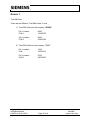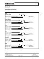
1
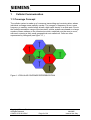
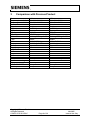
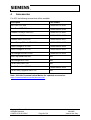
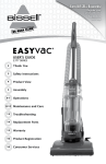
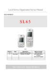
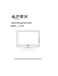
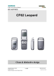
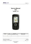
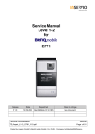
Local Service Organization Service Manual
BE INSPIRED
A70
Release
Date
Department
Notes to changes
V1.0
06.06.2005
COM D CCQ SLI APAC
New Document
Our innovation shapes the future
A70 Level 2 Service Manual
Table of Contents
1
CELLULAR COMMUNICATION………………………………………..… … … . 3
2
KEY FEATURES ……...……………………………………………………………….6
3
COMPARISION WITH PREVIOUS PRODUCT …………………………………….8
4
ACCESSORIES ……………………………………………………………………….9
5
UNIT DESCRIPTION OF A70...…………………………………………………......11
6
DISASSEMBLY OF A70........................................................................................13
7
REASSEMBLY OF A70........………………………………………………………..18
8
MOBILE SOFTWARE PROGRAMMING ……………………………………….....19
9
SIEMENS SERVICE EQUIPMENT USER MANUAL …………………………….22
10
JPICS INTERNET.……………………………………………………………………23
11
INTERNATIONAL MOBILE EQUIPMENT IDENTITY, IMEI…….………………..29
12
GENERAL TESTING INFORMATION……………………………….……………..30
Annex 1……………………………………………………………………………….……….35
Annex 2…………………………………………………………………………….………….36
Copyright © Siemens Pte Ltd.
All Rights Reserved
COM D CCQ SLI APAC
Page 2 of 36
Mai 2005
Internal Use Only
A70 Level 2 Service Manual
1
Cellular Communication
1.1 Coverage Concept
The cellular system is made up of numerous transmitting and receiving sites, whose
individual coverage areas partially overlap. The concept of frequency re-use, same
frequency is used by several sites, allows a high traffic density in a wide area. Due to
the limited transmission range of the terminals, cellular systems are based on a large
number of base stations on the infrastructure side, scattered over the area to cover,
with each covering a fairly small geographical zone called cell. Cells are often
represented by hexagons (see figure 1.1.).
Figure 1.1 CELLULAR COVERAGE REPRESENTATION
Copyright © Siemens Pte Ltd.
All Rights Reserved
COM D CCQ SLI APAC
Page 3 of 36
Mai 2005
Internal Use Only
A70 Level 2 Service Manual
1.2 GSM Network Architecture
GSM network can be broadly divided into three broad parts, namely:
1. Mobile Station (MS) carried by the subscriber
2. Base Station Sub-system (BSS) which controls the radio link with the mobile
station.
3. Mobile Switching Center (MSC) which performs the switching of calls between the
mobile users, and between mobile and fixed network users.
FIGURE 1.2 GSM ARCHITECTURE
Each mobile station is given a unique identity. As soon as the mobile phone is turned
on, it registers with the network and is authenticated, as such the network could
always find the mobile phone. Larger amount of data is being exchanged to and from
the following functional blocks in the MSC:
Visitor Location Register, VLR
Contain relevant data of all mobiles located in the serving MSC, but not belong to the
area.
Home Location Register, HLR
Stores identity and user data of all the mobile users belonging to the area.
Authentication Center, AUC
Provides the HLR with different sets of parameters to complete the authentication of
the mobile station.
Equipment Identity Register, EIR
An option the network operator can use to enforce security. With this feature the
network can identify defective or stolen mobile that may not be used in the network.
Copyright © Siemens Pte Ltd.
All Rights Reserved
COM D CCQ SLI APAC
Page 4 of 36
Mai 2005
Internal Use Only
A70 Level 2 Service Manual
1.3 Subscriber Identity Module (SIM)
SIM is a smart card which has a computer and memory chip that is permanently
installed in the mobile equipment. It comes in either the size of a credit card or
smaller version known as the plug-in SIM.
SIM card using 5V technology is not supported.
The subscriber information, which includes a unique number called the International
Mobile Subscriber Identity (IMSI) is stored in the SIM card. SIM card identifies the
subscriber to the network.
To protect the SIM card from improper use, a security feature, a four digits personal
identification number (PIN), is built in. The PIN is stored in the card and can be
changed by the subscriber. PIN2 Is required for additional functions available with a
special SIM card (Consult the operator for more Information about the PIN 2).
A code (PUK) is provided for unlocking the SIM card if the SIM card is blocked.
Copyright © Siemens Pte Ltd.
All Rights Reserved
COM D CCQ SLI APAC
Page 5 of 36
Mai 2005
Internal Use Only
A70 Level 2 Service Manual
2
Key Features
Bands
Battery
Stand-by Time
Talk Time
SIM Card
GSM Antenna
Dimensions
Weight
Charging time
Receiver Sensitivity
•
•
•
•
•
•
•
Triple Band E-GSM 900 / GSM 1800 / GSM 1900
EGSM Phase 2 / phase 2+
Li-Ion Battery Pack
Nominal Voltage : 3.7V
Nominal Capacity : 600 mAh
up to 250 h (standard battery)
up to 300 min (standard battery)
• Small (”Plug In”) 1.8 V or 3V SIM card (Phase II)
• To insert the SIM card, the battery pack must be
removed.
• Integrated triple band antenna for EMEA/APAC.
• 101 x 45 x 21 mm (L x W x H)
• 78 g
• < 2 h for 100%
• GSM 900: -102dBm (Specification, static & with fading)
• GSM 1800/1900: -102 dBm (Specification, static & with
fading)
Receiver sensitivity must comply with the corresponding GSM
recommendations in all operating conditions (temperature,
battery level, etc)
•
Transmitter Power
•
GSM 900: nominal 2W (Specification: Class 4 Mobile
phone)
GSM 1800/1900: nominal 1W (Specification: Class 1
Mobile phone)
Transmitter output characteristics is according to GSM 11.10
specification implying all specified operating conditions
(Temperature, battery level ...).
Speech Codec
Temperature
Range
Transmitter set points will be specified for GSM and PCN when
typical values and statistical values become available.
• Half Rate, Full Rate, Enhanced Full Rate and Adaptive
Multi Rate speech coders are available as standard.
• -100C to +550C (Normal operation)
• -300C to +850C (Storage capability)
Copyright © Siemens Pte Ltd.
All Rights Reserved
COM D CCQ SLI APAC
Page 6 of 36
Mai 2005
Internal Use Only
A70 Level 2 Service Manual
Display
12-Block Keypad
Acoustics
•
•
•
•
•
•
•
•
•
•
•
•
•
•
•
•
•
•
•
Copyright © Siemens Pte Ltd.
All Rights Reserved
COM D CCQ SLI APAC
Type: Full Dot Matrix
Resolution: 101 x 64 Pixel
Colours: B & W
Technology: F-STN (Epson)
Dot size: 0.277mm x 0.297mm
Active area: 29.477mm x 19.953mm
Visible area: 33.0mm x 23.2mm
Illumination: Min 2.0cd/mm
Operating Temp.: -200C to +550C
12-digit block (0-9, #, *) small letters
two function keys (SEND, END)
ON/OFF key combined with the END key
2 way navi key
2 softkeys on left & right position
comfortable earpiece with optimal acoustics
unidirectional microphone (same as Puma)
different call melodies (for the amount see SW product
description). All melodies with increasing volume because
of the danger of acoustic shock. Additional measures to
protect from acoustic shock, see SW product description.
different selectable volume levels for handset and ringer
mode (for the amount see SW product description)
mount see SW product description)
Page 7 of 36
Mai 2005
Internal Use Only
A70 Level 2 Service Manual
3
Comparison with Previous Product
Feature
Frequency bands/int’l
Frequency bands/LAM
Product Class
Form factor
PCB thickness
A65
900/1800/1900MHz
850/1800/1900MHz
Class A
Bar phone
1.106MM
A70
900/1800/1900MHz
850/1800/1900MHz
Class A
Bar phone
1.106MM
PCB outline
BB chipset
RF solutions
PMU ASIC
Same as Puma
EGOLDlite
B6E/SD2
Salzburg 75/Twigo 3+ 75
Same as Puma
EGOLDlite
B6E/SD2
Salzburg 75/Twigo 3+ 75
Flash
64Mbit
32Mbit
RAM
Display
Battery
Feature set
USB/IrDA/Bluetooth
MMS
Java
WAP
Exchangable housing
Speaker
Lead free technology
Clip on camera
NO ID CONCEPT
Navi key
16Mbit P-SRAM
101X80, 4k, C-STN
Same as Puma
A60
None
None
None
Yes
No
Penelope
Yes
No
Battery Cover
4-way
16Mbit P-SRAM
101X64, b/w
Same as Puma
A52
None
No
No
No
No
Same as Penelope
No
No
Battery Cover
2-way
Copyright © Siemens Pte Ltd.
All Rights Reserved
COM D CCQ SLI APAC
Page 8 of 36
Mai 2005
Internal Use Only
A70 Level 2 Service Manual
4
Accessories
For A70, the following accessories will be available.
Description
Part number
Belt Case FCL-600
L36880-N7101-A120
Tour Case FCT-650
L36880-N5601-A149
Headset Purestyle HHS-610
L36880-N7101-A500
Headset HHS-510
L36880-N5601-A108
Headset Basic HHS-500
L36880-N5601-A107
Li-Ion Battery 700mAh EBA-510
L36880-N5601-A100
Travel Charger ETC-500
L36880-N5601-A104
Travel Charger ETC-510
L36880-N5601-A105
Car Charger Plus ECC-600
L36880-N7101-A109
Desk Top Stand EDS-600
TBC
Car Charger ECC-500
TBC
Car Kit Easy HKP-700
TBC
Car Kit Portable HKP-500
L36880-N5601-A109
Car Kit Easy Upgrade HKO-700
TBC
Note: Visit the Communication Market for updated accessories:
https://communication-market.siemens.de/
Copyright © Siemens Pte Ltd.
All Rights Reserved
COM D CCQ SLI APAC
Page 9 of 36
Mai 2005
Internal Use Only
A70 Level 2 Service Manual
4.1 A70 Interface to accessories
The phone has a fully compatible interface to accessories. The connectors (I/O) are
identical to the 75 Family.
Mechanical interfaces are defined on the mobile phone to make sure that the accessories
are compatible across the whole L75 platform.
The design is released by AD regarding compatibility to Accessory Devices.
Slim Lumberg I/O Connector
Copyright © Siemens Pte Ltd.
All Rights Reserved
COM D CCQ SLI APAC
Page 10 of 36
Mai 2005
Internal Use Only
A70 Level 2 Service Manual
5
Unit Description of A70
The Phone is part of the 75 platform with the following specific features:
• Integrated tri-band antenna
• B/W Display
• The concept of the device is optimized regarding design-to-cost and easy-toassemble.
The phone consists of equipped upper case, keypad, equipped PCB, equipped lower
case and battery cover.
The PCB is based on the 75 Platform.
All electro mechanic components are overtaken from Lion and Barracuda,
The RF chamber and shielding is new for 75 platform.
Each of the preassemblies, upper and lower cases are designed to be automatically
mounted and checked.
These preassemblies are designed to be easily assembled.
The strategy of use of similar components is completely realised.
Copyright © Siemens Pte Ltd.
All Rights Reserved
COM D CCQ SLI APAC
Page 11 of 36
Mai 2005
Internal Use Only
A70 Level 2 Service Manual
5.1 Exploded View of A70
Upper case shell w/o
Keypad with
Earphon
Display
Main
Microphon
Vibramoto
Lower mounting
Screw
Battery Li-
Battery
Copyright © Siemens Pte Ltd.
All Rights Reserved
COM D CCQ SLI APAC
Page 12 of 36
Mai 2005
Internal Use Only
A70 Level 2 Service Manual
6
Disassembly of A70
Note: ESD concept; the internal circuits will be more susceptible to ESD because of
the use of exchangeable housing. The construction of the internal block must be/is
designed, in the best possible way, to protect the circuit against sparks.
The keypad must be completely closed to prevent any occurrence of an ESD
disruptive discharge.
The SIM contacts may be open, thus reachable for ESD contact discharge. This
could lead to damage or destruction of the E-Goldlite pins.
It is a requirement for the service personnel to observe ESD protection rules while
performing servicing the A70.
Step 1
Step 2
Back View of the A70
Front view of the A70
Step 3
Remove Battery cover.
Copyright © Siemens Pte Ltd.
All Rights Reserved
COM D CCQ SLI APAC
Page 13 of 36
Mai 2005
Internal Use Only
A70 Level 2 Service Manual
Step 4
Remove Battery
Step 5
Remove SIM Card: 1) move latch upwards; 2) SIM Card will eject from holder
Step 6
Remove the 4 screws (as indicated) with T5 Plus screw driver.
Copyright © Siemens Pte Ltd.
All Rights Reserved
COM D CCQ SLI APAC
Page 14 of 36
Mai 2005
Internal Use Only
A70 Level 2 Service Manual
Step7
Remove Lower mounting frame with Vibra and Micro.
Step 9
Remove Virbamotor.
Copyright © Siemens Pte Ltd.
All Rights Reserved
COM D CCQ SLI APAC
Page 15 of 36
Remove Microphone.
Mai 2005
Internal Use Only
A70 Level 2 Service Manual
Step 10
Remove PCB
Step 11
Remove Display module.
Place foil over display module for protection.
Step 12
Remove Earphone
Copyright © Siemens Pte Ltd.
All Rights Reserved
COM D CCQ SLI APAC
Page 16 of 36
Mai 2005
Internal Use Only
A70 Level 2 Service Manual
Step 13
Remove Keypad.
Step 14
Fully disassembled A70
Copyright © Siemens Pte Ltd.
All Rights Reserved
COM D CCQ SLI APAC
Page 17 of 36
Mai 2005
Internal Use Only
A70 Level 2 Service Manual
7
Reassembly of A70
For the reassembly of the A70, reverse the disassembly procedures from Step 13 to Step1.
However there are some areas to be taken note of during reassembling of the phone.
During the installation of the SIM card, make sure that the SIM card is inserted properly and that
the golden contact area is facing downwards. Insert the SIM card and push the latch downwards
to lock the SIM card into position.
Installation of the SIM card
During the installation of the battery, make sure that the hinges are properly in place (See picture
below). Otherwise the battery will not be able to fit into the phone properly.
When placing the screws, set Torque with 17cNm.
Copyright © Siemens Pte Ltd.
All Rights Reserved
COM D CCQ SLI APAC
Page 18 of 36
Mai 2005
Internal Use Only
A70 Level 2 Service Manual
8
Mobile Software Programming
The common mobile software available is divided into language groups. However, this
software does not contain the specific settings, such as ringing tones, greeting text, and
short dial list etc., required by the operator or service provider. Therefore, it is common to
have some menu item(s) differ in different variants or are not visible at all. These settings
are stored in different memory area of the mobile and will be activated depending on the
customer specific model or variant of the phone by a separate test step during the
production process.
Due to this separation of common mobile software and customer specific initialization, it
is possible to fulfil the demands of the market requiring customization and flexibility. As a
consequence the software programming process in the LSO is divided into two different
steps as followed:
- Software update to actual version and appropriate language group
- Programming of CUSTOMER SPECIFIC INITIALIZATION
Usage of GRT is mandatory!! For more detail check GRT User manual
Figure 1. A70 Software Programming Setup
Copyright © Siemens Pte Ltd.
All Rights Reserved
COM D CCQ SLI APAC
Page 19 of 36
Mai 2005
Internal Use Only
A70 Level 2 Service Manual
8.1 Mobile Software Updating
The software of the mobile, 65 series is loaded from a PC directly. Hardware
interconnection between the mobile and the PC is shown in Figure 1. Because of the new
type of external connector used since 55 series (Slim-Lumberg type) an additional
adaptor cable between mobile and boot adaptor is required. Table 1 listed all the
hardware requirements
If you use the battery dummy, make sure that the power supply voltage is correctly
adjusted.
Description
Part No.
Bootadapter 2000 incl. AC-Adapter, serial
cable and mobile connection cable
L36880-N9241-A200
IBM Compatible PC – Pentium
-
Adapter cable – Slim Lumberg to Old
F30032-P226-A1
TABLE 1. EQUIPMENT LIST FOR SOFTWARE PROGRAMMING
Copyright © Siemens Pte Ltd.
All Rights Reserved
COM D CCQ SLI APAC
Page 20 of 36
Mai 2005
Internal Use Only
A70 Level 2 Service Manual
8.2 Flow Chart for Software Upgrading
Plug in the Boot
Adaptor to the PC
and Mobile
Start the SWUP
program
S/W upgrading in
progress
Connec t the AC
adaptor to the
Boot Adaptor
Select & Execute
the "Mobile S/W"
ERROR?
YES
NO
P o we r u p B o ot
Adaptor & check
LED.
ERROR?
NO
TEST Mobile
YES
Check
H/W setup = S/W
Take note of error
and repeat
process
Check AC Adaptor
OK?
Feedback Error to
Tech. Supp. Dep
OK?
Correct Settings
OK?
YES
NO
YES
END
NO
Faulty AC Adaptor
Faulty Boot
Adaptor
FLOW CHART FOR S/W PROGRAMMING PROCESS
Copyright © Siemens Pte Ltd.
All Rights Reserved
COM D CCQ SLI APAC
Page 21 of 36
Mai 2005
Internal Use Only
A70 Level 2 Service Manual
9
Siemens Service Equipment User Manual
Introduction
Every LSO repairing Siemens handset must ensure that the quality standards are
observed. Siemens has developed an automatic testing system that will perform all
necessary measurements. This testing system is known as:
Siemens Mobile Service Equipment
All mobile Phones have to be tested with the GRT-Software.
The Service Partner is responsible to ensure that all required hardware is
available.
For additional Software and Hardware options as well as the supported GRT
equipment, please check the GRT User manual
Copyright © Siemens Pte Ltd.
All Rights Reserved
COM D CCQ SLI APAC
Page 22 of 36
Mai 2005
Internal Use Only
A70 Level 2 Service Manual
10
JPICS (Java based Product Information Controlling System)
Overview
The following functions are available for the LSO:
•
General mobile information
•
Generate PINCODE
•
Generate SIMLOCK-UNLOCK-Code
•
Print IMEI labels
•
Lock, Unlock and Test the BF-Bus
Copyright © Siemens Pte Ltd.
All Rights Reserved
COM D CCQ SLI APAC
Page 23 of 36
Mai 2005
Internal Use Only
A70 Level 2 Service Manual
The access to the JPICS server which is located in Kamp-Lintfort is protected by chip
card and in addition using secure socket layer (SSL) connection.
The JPICS server is only available for authorized users with a specially coded chip card.
These chip cards and the administration of the JPICS web server and the PICS
database-server can only be provided by the JPICS-TRUST-Center of the responsible
department in Kamp-Lintfort.
In case of any questions or requests concerning chip cards or administration of
the databases please ask your responsible Siemens Customer Care Manager.
Copyright © Siemens Pte Ltd.
All Rights Reserved
COM D CCQ SLI APAC
Page 24 of 36
Mai 2005
Internal Use Only
A70 Level 2 Service Manual
Installation overview
The following installation description assumes that a web browser is already installed.
JPICS is tested with the following browsers
1. Internet Explorer Version 5.5 and higher
2. Netscape Version 6 and higher
For further information regarding supported browsers, browser version and supported
operating systems, see the Sun FAQ's.
Here is a step by step instruction to install all the required components:
It is necessary to follow this order!
1. Card reader (Omnikey)
2. CardOS interface (Siemens)
3. JPICS Certificates
4. Java Plugin JVM/JRE (Sun)
5. Java additional components
Every user is responsible for a proper installation matching the license
agreements.
For installation and further access you need the following:
1. The JPICS Installation-CD
2. A chip card. Chip cards can be ordered via your responsible Customer Care
Manager within Siemens.
3. A supported chip card reader (Smarty or Siemens B1) in order to access your chip
card.
Remark:
We recommend using Siemens B1 reader. Similar device to B1 is Cardman 9010.
Copyright © Siemens Pte Ltd.
All Rights Reserved
COM D CCQ SLI APAC
Page 25 of 36
Mai 2005
Internal Use Only
A70 Level 2 Service Manual
Generate Codes
In the module “Generate Codes“you can choose to generate:
- Master – Phonecodes
- Simlock Unlock – Codes
Master - Phonecodes
The Master – Phonecode is used to unlock blocked mobiles.
Master – Phonecodes can only be supplied for mobiles which have been delivered
in a regular manner.
Copyright © Siemens Pte Ltd.
All Rights Reserved
COM D CCQ SLI APAC
Page 26 of 36
Mai 2005
Internal Use Only
A70 Level 2 Service Manual
Simlock Unlock - Code
The Simlock-Unlock-Codes can only be generated if the following conditions are
given:
- Mobile must have an active Simlock inside.
- The user must be given the authorization to obtain Simlock Unlock- Codes for the
variant of the operator to which the mobile was delivered last time.
Copyright © Siemens Pte Ltd.
All Rights Reserved
COM D CCQ SLI APAC
Page 27 of 36
Mai 2005
Internal Use Only
A70 Level 2 Service Manual
Printing IMEI label
The module “Print IMEI label” offers the possibility to re-print IMEI labels for mobiles
again.
You are able to print 1 label in just one step.
To prevent that misaligned labels are being printed, the setting "Print test labels =
" is
activated as default. After having printed a well-aligned test label you can uncheck the
setting and print the correct label.
Hint:
For correct printing of IMEI labels you must have a Zebra – label printer with special
material that fits for label printing. This printer has to be connected to local LPT1
printer port (also see Installation of IMPRINT) and MUST feature a printing resolution
of 300dpi.
Copyright © Siemens Pte Ltd.
All Rights Reserved
COM D CCQ SLI APAC
Page 28 of 36
Mai 2005
Internal Use Only
A70 Level 2 Service Manual
11
International Mobile Equipment Identity, IMEI
The mobile equipment is uniquely identified by the International Mobile Equipment
Identity, IMEI, which consists of 15 digits. Type approval granted to a type of mobile is
allocated 6 digits. The final assembly code is used to identify the final assembly plant and
is assigned with 2 digits. 6 digits have been allocated for the equipment serial number for
manufacturer and the last digit is spare.
The part number for the A70 is L36880-N2770-Axx-x where the last 4 letters specify the
housing and software variant.
Re-use of IMEI label is possible by using a hair-dryer to remove the IMEI label.
On this IMEI label, Siemens has also includes the date code for production or service,
which conforms to the industrial standard DIN EN 60062. The date code comprises of 2
characters: first character denotes the Year and the second character denotes the
Month.
For example: M3
CODE
M
N
P
R
S
YEAR
2000
2001
2002
2003
2004
MONTH
MARCH
APRIL
MAY
JUNE
JULY
CODE
3
4
5
6
7
TABLE 2 DIN EN 60062 DATE CODE
To display the IMEI number, exit code and SW/HW version, key: *#06#.
Copyright © Siemens Pte Ltd.
All Rights Reserved
COM D CCQ SLI APAC
Page 29 of 36
Mai 2005
Internal Use Only
A70 Level 2 Service Manual
12
General Testing Information
General Information
The technical instruction for testing GSM mobile phones is to ensure the best repair
quality.
Validity
This procedure is to apply for all from Siemens AG authorized level 2 up to 2.5e
workshops.
Procedure
All following checks and measurements have to be carried out in an ESD protected
environment and with ESD protected equipment/tools. For all activities the
international ESD regulations have to be considered.
Get delivery:
Ensure that every required information like fault description, customer data
a.s.o. is available.
Ensure that the packing of the defective items is according to packing
requirements.
Ensure that there is a description available, how to unpack the defective items
and what to do with them.
Enter data into your database:
(Depends on your application system)
Ensure that every data, which is required for the IRIS-Reporting is available in
your database.
Ensure that there is a description available for the employees how to enter the
data.
Copyright © Siemens Pte Ltd.
All Rights Reserved
COM D CCQ SLI APAC
Page 30 of 36
Mai 2005
Internal Use Only
A70 Level 2 Service Manual
Incoming check and check after assembling:
!! Verify the customers fault description!!
After a successful verification pass the defective item to the responsible
troubleshooting group.
If the fault description can not be verified, perform additional tests to save time
and to improve repair quality.
- Switch on the device and enter PIN code if necessary unblock phone.
- Check the function of all keys including side keys.
- Check the display for error in line and row, and for illumination.
- Check the ringer/loudspeaker acoustics by individual validation.
- Perform a GSM Test as described on page 32.
Check the storage capability:
Check internal resistance and capacity of the battery.
Check battery charging capability of the mobile phone.
Check charging capability of the power supply.
Check current consumption of the mobile phone in different mode.
Visual inspection:
Check the entire board for liquid damages.
Check the entire board for electrical damages.
Check the housing of the mobile phone for damages.
SW update:
Carry out a software update and data reset according to the master tables and
operator/customer requirements.
Repairs:
The disassembling as well as the assembling of a mobile phone has to be
carried out by considering the rules mentioned in the dedicated manuals. If
special equipment is required the service partner has to use it and to ensure
the correct function of the tools.
If components and especially soldered components have to be replaced all
rules mentioned in dedicated manuals or additional information e.g. service
information have to be considered
Copyright © Siemens Pte Ltd.
All Rights Reserved
COM D CCQ SLI APAC
Page 31 of 36
Mai 2005
Internal Use Only
A70 Level 2 Service Manual
GSM Test:
Connect the mobile/board via internal antenna (antenna coupler) and external
antenna (car cradle) to a GSM tester.
Use a Test SIM.
Skip GSM 900/GSM1800 or GSM1900 test cases if not performed by the
mobile phone.
Copyright © Siemens Pte Ltd.
All Rights Reserved
COM D CCQ SLI APAC
Page 32 of 36
Mai 2005
Internal Use Only
A70 Level 2 Service Manual
Copyright © Siemens Pte Ltd.
All Rights Reserved
COM D CCQ SLI APAC
Page 33 of 36
Mai 2005
Internal Use Only
A70 Level 2 Service Manual
Final Inspection:
The final inspection contains:
1) A 100% network test (location update, and set up call).
2) Refer to point 3.3.
3) A random sample checks of:
- data reset (if required)
- optical appearance
- complete function
4) Check if PIN-Code is activated (delete the PIN-Code if necessary).
Basis is the international standard of DIN ISO 2859.
Use Normal Sample Plan Level II and the Quality Border 0,4 for LSO.
Remark: All sample checks must be documented.
Copyright © Siemens Pte Ltd.
All Rights Reserved
COM D CCQ SLI APAC
Page 34 of 36
Mai 2005
Internal Use Only
A70 Level 2 Service Manual
Annex 1
Test SIM Card
There are two different “Test SIM Cards” in use:
1) Test SIM Card from the company “ORGA”
Pin 1 number:
PUK 1
:
0000
12345678
Pin 2 number:
PUK 2
:
0000
23456789
2) Test SIM Card from the company “T-D1”
Pin 1 number:
PUK
:
1234
76543210
Pin 2 number:
PUK 2
:
5678
98765432
Copyright © Siemens Pte Ltd.
All Rights Reserved
COM D CCQ SLI APAC
Page 35 of 36
Mai 2005
Internal Use Only
A70 Level 2 Service Manual
Annex 2
Battery Date Code overview
Varta
Date code example
N 9 A VA
Year (N:2001, O:2002...)
Month (1:Jan, 2:Feb,…9:Sep, O:Oct, N:Nov, D:Dec)
Revision Letter (A, B,…)
Hitachi / Maxwell
Date code example
Supplier Code
(Maker’s marking)
N 9 A MX
Year (N:2001, O:2002...)
Month (1:Jan, 2:Feb,…9:Sep, O:Oct, N:Nov, D:Dec)
Revision Letter (A, B,…)
Sanyo
Date code example
Supplier Code
(Maker’s marking)
N 9 A SY
Year (N:2001, O:2002...)
Month (1:Jan, 2:Feb,…9:Sep, O:Oct, N:Nov, D:Dec)
Revision Letter (A, B,…)
NEC
Date code example
Supplier Code
(Maker’s marking)
N 8 A NT
Year (N:2001, O:2002...)
Month (1:Jan, 2:Feb,…9:Sep, O:Oct, N:Nov, D:Dec)
Revision Letter (A, B,…)
Panasonic
Date code example
Supplier Code
(Maker’s marking)
O N A PAN
Year (N:2001, O:2002...)
Month (1:Jan, 2:Feb,…9:Sep, O:Oct, N:Nov, D:Dec)
Revision Letter (A, B,…)
Sony
Date code example
Supplier Code
(Maker’s marking)
P N A SO
Year (O:2002, P:2003...)
Month (1:Jan, 2:Feb,…9:Sep, O:Oct, N:Nov, D:Dec)
Revision Letter (A, B,…)
Copyright © Siemens Pte Ltd.
All Rights Reserved
COM D CCQ SLI APAC
Supplier Code
(Maker’s marking)
Page 36 of 36
Mai 2005
Internal Use Only