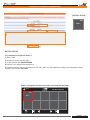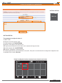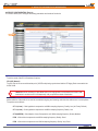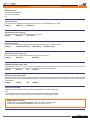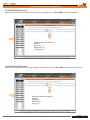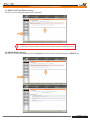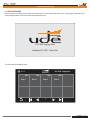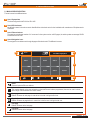
1
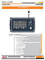
IPU-100P Audio over IP PAGING DESK User Manual USB 00.00 IPU-100P Paging Desk IPU-100P 1001 Zona 1 1002 Zona 2 1003 Zona 3 1004 1005 Zona 4 ON Zona 5 FAULT 1006 Zona 6 1007 Zona 7 1008 Zona 8 1009 1010 Zona 9 Zona 10 1 INDEX MESSAGE SPEECH PAGE 1.- TECHNICAL DATA 2 2.- TYPICAL APPLICATION OF IPU-100P 3 4 6 7 9 12 13 14 20 22 22 23 23 24 3.- FRONT AND REAR VIEW 4.- DEVICE CONFIGURATION (WEBSERVER) 4.1.- Home page (HOME) 4.2.- SIP Configuration 4.3.- Extension SIP Configuration 4.3.1.- Erasing & Editing 4.3.2.- P.A. Zones edit page 4.4.- Device Configuration (Device) 4.5.- Time Configuration (TIME) 4.6.- Date Configuration (DATE) 4.7.- Reset to Factory 4.8.- Remote Reboot 5.- INITIALIZE PROCESS 24 25 26 27 5.1.- Initialize process 5.2.- P.A. Buttons Display 5.3.- Main screen description 5.4.- Select Zones UNION DESARROLLOS ELECTRONICOS Barcelona Avda. BARCELONA, 24 08970 - SANT JOAN DESPÍ BARCELONA - ESPAÑA UDE reserves the right to modify the technical characteristics of its products without previous notice Tel: +34 93 477 28 54 Fax: +34 93 261 17 52 [email protected] Madrid C/ LUIS I, 88, 3ª planta 28031 - MADRID ESPAÑA Tel: +34 91 311 60 76 Fax: +34 91 450 19 97 [email protected] PUBLIC ADDRESS Systems Rev. 0 610.462A 1 28 IPU-100P 1.- TECHNICAL DATA The public address system for IP networks of UNION DESARROLLOS ELECTRONICOS allows the creation of conventional PA and security systems, allowing interconnecting with IP devices following SIP standard. Unión Desarrollos Electrónicos also offers the IPU-360 SIP server that will centralize and coordinate all communication of IP paging elements ensuring maximum functionality of all of them, with minimal risk. The IPU-100P paging desk allow the user to manage the IP PA system calling individual or groups of zones with user friendly graphic interface in a 7” full color touch screen. The IPU-100P is build with a gooseneck microphone and also with an audio socket for a XLR handheld microphone with remote switching contact. The IPU-100P characteristics: · Manage the zone selection and make voice calls. 7” TFT full colour touch screen 5-pin XLR connector for handheld microphone. Direct audio & data link with IPU-100 or IPU-1025. Web server configuration. 100% WIFI compatible (accessories required). 24Vdc power supply connector (for cables greater than 50m). USB connector for firmware update. High quality gooseneck microphone The IPU-100P is the IP solution for manage PA zones is a highly versatile range of installations: schools, hotels, retail spaces, office buildings, airports… giving proper solutions from small locations to a more complex installations. The graphic interface gives a great navigation experience to the operator, from small places to the biggest ones. Technical staff can program until 250 zones in 25 pages with specific name in each zone, configuration process is made with an easy web interface. IPU-100P shall be installed with IPU-100 or IPU-1025 combination and connected with the audio link bus, where audio and information travels. TECHNICAL DATA VALUES Gooseneck microphone Black gooseneck condenser microphone. Frequency response: 50Hz-16KHz Max. Input: 130dB SPL. To connect handheld microphone with XLR 5c connector. Microphone XLR socket USB port Frontal LEDs (only informative) Rear LEDs (only informative) PA zones USB 2.0 Type-A. Power ON, FAULT, MESSAGE. Device FAIL, LINK OK, LINK FAIL, DATA IN, DATA OUT, AUDIO IN, AUDIO OUT The user can manage until: 250 PA zones buttons (maximum). 250 extensions in each PA zone button (maximum). 15 group name characters in each PA zone button. Configuration Through a web server interface from the IPU-100 / IPU-1025 to the IPU-100P, it is possible to: Check the right desk control work. Password managing. Configuration: SIP parameters / LAN parameters / PA extensions / Hour & date. Security Power supply 8 alphanumeric characters with ASCII between 32 and 127 in IPU-100 or IPU-1025. Main: AC Adaptor (recommended): 24Vdc (18..30V). 0.9A PPTC internal fuse (resettable). Bus AUDIO LINK from IPU-100 or IPU-1025: 24Vdc (18..30V). Consumption Operation temperature Humidity Dimensions Weight 6W max. at 24Vdc. -5 a +45ºC (0 a +40ºC, recommended). Color Grey (Aluminium). 5% a 95%, without condensation. 318 x 188 x 73 mm. 1.4 Kg. User Manual - IPU-100P Rev. 0 610.462A 2 28 IPU-100P 2.- TYPICAL APPLICATION OF IPU-100P The figure 1 shows a typical connection between the desk control IPU-100P and the IP network, for that is necessary an IPU-100 or IPU-1025 codifier / decodifier. Cable UTP IPU-100P Protocolo RS-485 + AUDIO USB Cable UTP Protocolo IP IPU-100 IP IPU-100P ON DEVICE FAULT ON OK FAULT CALL IN OUT CONFIG NET USB MESSAGE ACTIVITY SPEECH IPU-1025 Figure 2 provides a configuration example of the PA system for IP networks. The encoder / decoder and audio manager, IPU-100 model, is the element that allows the decoding process of audio sent digitally to 0dB audio signal. The IP Paging Desk, model IPU-100P, through an intuitive graphical interface, built-in a 7 " color touch screen, allows the operator to navigate and select the areas where to send a message using the microphone on the same device. The SIP server, IPU-360, which acts as intermediary between all IP devices over the LAN, coordinating the tasks. The different elements allow multiple configurations and connections, adding flexibility to combine the wide range of amplifiers, preamps, power amps, ..., of UNIÓN DESARROLLOS ELECTRÓNICOS. IPU-100P IPU-100 USB IPU-100 IPU-100P DEVICE ON ON OK FAULT CALL IN OUT CONFIG NET FAULT USB ACTIVITY Engineered and made in E.U. POWER AMPLIFIER MESSAGE SPEECH IP IPU-100 IPU-100 DEVICE ON OK FAULT CALL IN OUT CONFIG NET USB ACTIVITY IPU-1025 Engineered and made in E.U. IPU-1025 IPU-1025 DEVICE ON OK FAULT CALL IN OUT CONFIG NET USB ACTIVITY Engineered and made in E.U. IPU-100 IPU-100 DEVICE ON IPU-360 OK FAULT CALL IN OUT CONFIG NET ACTIVITY Engineered and made in E.U. User Manual - IPU-100P USB POWER AMPLIFIER Rev. 0 610.462A 3 28 IPU-100P 3.- FRONT VIEW / REAR VIEW 2 1 3 FRONT REAR 12 11 8 USB IPU-100P 4 ON MIC I/O AUDIO IN OUT DATA IN OUT LINK OK FAIL FAIL DEVICE DC IN 5 FAULT 6 MESSAGE 7 SPEECH 17 16 15 14 13 10 9 CONTROLS, CONNECTORS AND INDICATORS 1 TOUCHSCREEN. 10 zone touch- buttons per page ready to broadcast public address message. 2 MICROPHONE. Gooseneck microphone. Length: 300mm. 3 USB CONNECTOR. The USB connector allows the firmware update. 4 LED ON. This indicator shows the equipment is properly powered and main application is running. 5 LED FAULT. LED is disabled. 6 LED MESSAGE. LED is disabled. 7 PTT BUTTON. A push-to-talk (PTT) button to start the call when at least one zone is selected. 8 LED FAIL DEVICE. This indicator is activated when there is a connection problem with IPU-100 or IPU-1025. Remember! If you experience problems with the DEVICE FAIL, so if it ever turns on sporadically, then it is recommended to contact with your local network administrator (LAN). 9 LED LINK FAIL. This indicator is activated when exist a wrong data transmission with IPU-100 or IPU-1025. Remember! If you experience problems with the LINK FAIL, so if it ever turns on sporadically, then it is recommended to reboot the IPU-100P and IPU-100 or IPU-1025 to solve the communication problem between them. If the problem is no solve it, contact the technical staff of the installation. 10 LED LINK OK. This indicator is activated when exists a right data transmission with IPU-100 or IPU-1025. 11 LED DATA OUT. This indicator shows data modulation sent from IPU-100P . 12 LED DATA IN. This indicator shows data modulation sent to IPU-100P. 13 LED AUDIO OUT. This indicator shows audio modulation from the gooseneck or external microphone. Remember! If you experience problems with the LED AUDIO OUT, and never turn on, contact the technical staff to guarantee the right operation. 14 LED AUDIO IN. LED is disabled. User Manual - IPU-100P Rev. 0 610.462A 4 28 IPU-100P 3.- FRONT VIEW / REAR VIEW 15 DC IN. Jack to connect 24Vdc external power supply. (Model: IPW-25). 24 VDC Conexión fuente de alimentación al pupitre IPU-100P. IPU-100/P MIC I/O AUDIO IN OUT DATA IN OUT LINK OK FAIL FAIL DEVICE DC IN IPU-100/P IPW-25 IPW-25 24 VDC / 1,65 A 100-240 VAC 100/230 VAC - 50 Hz Conexión mediante cable UTP al codificador IPU-100 o IPU-1025. IP DISTANCIA MENOR DE 50 metros IPU-100 IPW-25 IPU-1025 TL MADE IN SPAIN LAN AUDIO LINK MIC +24VDC DC IN I/O AUDIO IN OUT DATA IN OUT LINK OK FAIL FAIL DEVICE DC IN IPW-25 24 VDC / 1,65 A 100/230 VAC - 50 Hz TL IPU-1025 IPU-100/P 100-240 VAC The IPU-100P has 2 powering methods available; the power input by the IPW-25 adaptor, is the highest-priority entry and disables the rest. The less priority power is the audio link power supply. 16 I / O. This connector allows connection of an IPU-100P or allows the expansion and control, of external devices through the digital bus, also has a balanced analog audio input and one output that allow the exchange of audio between the IP Paging Desk and the IPU-100 (encoder / decoder). We recommend using UTP wiring to connect both devices. The IPU-100P (IP Paging Desk) can be powered via the AUDIO LINK when you are less than 50 meters of the IPU-100. 8 1 BROWN BROWN-WHITE GREEN BLUE-WHITE BLUE GREEN-WHITE ORANGE ORANGE-WHITE 8 7 6 5 4 3 2 1 EIA/TIA-568B STRAIGHT CABLE EIA/TIA-568B 8 7 6 5 4 3 2 1 BROWN BROWN-WHITE GREEN BLUE-WHITE BLUE GREEN-WHITE ORANGE ORANGE-WHITE 8 1 4 17 EXTERNAL MICROPHONE. The XLR 5c socket allow to connect handheld microphones with push to talk switch, Unión Desarrollos Electrónicos recommends to use the CM-23 microphone. 5 CM-23 1 1 5 2 2 3 4 XLR 3 User Manual - IPU-100P Rev. 0 610.462A 5 28 IPU-100P 4.- DEVICE CONFIGURATION (WEBSERVER) EXTENSION SIP CONFIGURATION (ONLY IPU-100P mode). The public address zone configuration with an IPU-100P desk control must be done with a IPU-100 codifier. It is not possible to make the desk control configuration with the touch screen. The extension web server of the IPU-100 menu will allow erasing all IPU-100P zone buttons or editing the PAbuttons of the IPU-100P desk control. IPU-100P USB IPU-100P ON FAULT MESSAGE SPEECH Cable UTP Protocolo RS-485 + AUDIO IPU-100 IPU-100 DEVICE ON OK FAULT CALL IN OUT CONFIG NET USB ACTIVITY IPU-1025 Cable UTP Protocolo IP IP Cable UTP Protocolo IP ORDENADOR CON CONEXIÓN A RED User Manual - IPU-100P Rev. 0 610.462A 6 28 IPU-100P 4.- DEVICE CONFIGURATION (WEBSERVER) 4. DEVICE CONFIGURATION (WEBSERVER). The IPU-100 configuration is done by accessing to the IP address assigned to the device by the site administrator if you work in Manual mode assignment (Static Mode), or by the DHCP server if you work in automatic mode. Static IP by default is: 192.178.0.210 4.1 Home Page (HOME). The HOME page of the IPU-100 WEB application allows everyone access to configuration menus and display the status variables of the encoder / decoder. 5 1 IPU-100P 2 3 4 NOTA: UNION DESARROLLOS ELECTRONICOS reserves the right to modify all or part of WEB server design in order to offer a better product to their customers, which is why we may appear different from pictures provided in this document and results that you can get the product you have purchased. If you have any doubts consult the technical department of UDE. 1 Menus. This area specifies the different web pages with configuration parameters. 2 List of available Menus. This area displays the menu selection icons that the user can select for your device configuration. When the user selects a different menu to the "HOME" (or Main) will be asked to enter a password. If the password is right and match any of the previously stored will then open the desired menu, if not the access will be denied. ATTENTION: Computer security is a crucial aspect in IP networks. Technical staff is recommended not to store the password default on computers where you can access unqualified personnel to modify the settings of IP equipment. If you have any doubt, refer to the technical competence to avoid security problems. User Manual - IPU-100P Rev. 0 610.462A 7 28 IPU-100P 4.- DEVICE CONFIGURATION (WEBSERVER) 5 1 IPU-100P 2 3 4 3 Summary of Configuration Parameters. In this area you can check quickly, what are the basic parameters of the device's. Parameters are displayed relative to the Software Application version, the LAN settings (IP, MAC, DNS), the connection parameters to the SIP server (SIP Server IP, data ports, SIP Extension number, SIP authentication password, ...), volume values assigned to the audio inputs and outputs. 4 Status Monitor. In this area you can see three zones: LEDs status. It shows in real time the status (on, off, flashing) of all indicators present on the front panel. Activation signal status. Shows the state of the activation signals of different basic functions such as: VOX activated, MIC activated, etc... Sensor level status. It shows the voltage measurement of the sensors included on the device: 24V Adaptor, 24V Backup Battery, VOX signal level detected, Microphone supply. 5 Area 5: Time and Date. User Manual - IPU-100P Rev. 0 610.462A 8 28 IPU-100P 4.- DEVICE CONFIGURATION (WEBSERVER) 4.2 SIP CONFIGURATION (SIP). The configuration page allows you to configure SIP parameters to ensure the connection to the installation server IPU-360 (SIP server). The parameters configured here must be consistent with SIP server parameters of the system. IPU-100P The configuration parameters are: Enable SIP changes In case the checkbox is checked, the SIP parameters are available to be configured. If not the configuration parameters are blocked. UDE PA system The signaling communication with the server is SIP. Furthermore due to the public address characteristics, the codifiers and decoders requires additional information inside the standardized datagram. Choose ON to use the UDE PAsignaling information. In case of priority or IPU-100P installations, the box must stay in ON option. In case of 100% SIP standard compliance OFF option. SIP Server IPAddress (format: XXX.XXX.XXX.XXX): Defines the IP address where the SIP server host. It is required that the address contains the 12 numbers along with the 3 breakpoints. Example: SIP Server IP: 168.168.0.254 ¡Attention! It is MANDATORY for the correct operation of the IP AUDIO devices of UNION DESARROLLOS ELECTRONICOS that the SIP Server IP address is FIXED address (static type). User Manual - IPU-100P Rev. 0 610.462A 9 28 IPU-100P 4.- DEVICE CONFIGURATION (WEBSERVER) Remote Port (format: XXXXX): Define the management TCP port used by the IPU-360 (SIP server) to communicate with our IPU-100. The standard default value in the device is 05060, you should keep to ensure compatibility with different SIP servers. Remember to always use a configuration with 5 digits. Example: Remote Port: 05060 Local Port (format: XXXXX): Define the management TCP port used by the IPU-100 to communicate with the IPU-360 (SIP server). The standard default value in the device is 05060, you should keep to ensure compatibility with different SIP servers. Remember to always use a configuration with 5 digits. Example: Local Port: 05060 UDP Remote Port (format: XXXXX): Defines the data transmission UDP port (Voice / INFO) used by the IPU-360 (SIP server) to communicate with the IPU-100. The standard default value is 00000 (automatic mode), you should keep this value to ensure compatibility with different SIP servers. Remember to always use a configuration with 5 digits. Example: UDP Remote Port: 00000 UDP Local Port (format: XXXXX): Defines the data transmission UDP port (Voice / INFO) used by the IPU-100 to communicate with the IPU-360 (SIP server) on the installation. The standard default value is 05004 and it is recommended to keep compatibility with different SIP servers. Remember to always use a configuration with 5 digits. Example: UDP Local Port: 05004 Device extension (username) (from 4 to 8 numbers): It is the IPU-100 SIP identifier for registering to the IPU-360 (SIP server) to be identified as unique equipment in the SIP net, of the public address by IP protocol. In the systems with UDE Audio equipments, the extensions must be contained in a specific rank: Extensions from 1000 to 1999: Decoders Extensions from 2000 to 2999: Audio codifiers Extensions from 3000 to 3999: Music on hold equipments (do not use in other codifiers/decoders configuration) Extensions from 4000 to 4999: IP desk control (with IPU-100P). Choose the extension number depending in which application the IPU-100 should work. Some extensions ranks have additional features: Codifier extension between 2000 and 2499, do not activate the TM OUT in the decoder. Codifier extension between 2500 and 2999, activate the TM OUT in the decoder. All extensions between 4000 and 4999 will activate the decoder TM OUT. Example: Local Extension: 1002 2536 1589 4001 Authen. Device Extension (Username): (Max: 8 alphanumeric characters): Defines the user id in the system when it is working in a secure transmission mode. Example: Authen. ID: 12345678 AreaCo_1 This parameter is optional, if not required then leave it blank. Attention! If you have questions about your authenticated user name or password, contact your Network Administrator or technical staff in charge of the IPU-360 configuration (SIP server). Basic Alphanumeric characters are recommended (standard ASCII codes between 32 and 126), excluding special characters or accents to avoid to block the access in case of any network device or the server does not understand these characters. User Manual - IPU-100P Rev. 0 610.462A 10 28 IPU-100P 4.- DEVICE CONFIGURATION (WEBSERVER) Authen. Secret (Password): (Max: 8 alphanumeric characters): Defines the user password when it is working in a secure transmission mode. Example: Authen. PASSW.: zX_0!%¿# (No utilizar caracteres especiales) This parameter is required if the parameter "Authenticated ID" is active, otherwise please leave it blank. Display Name (Caller ID Name): (format: XXXX): Default Call (Streaming): (format: XXXX): Define the extension to call forr activating the background music or for the voice message broadcast from a microphone. Valid values for any extension must be between 3000 and 3999. Example: 3400 Default Call (streaming): SIP Receiver Priority Level (Max:01...min:99): (Not use) SIP Streaming Priority Level (Max:01...min:99): If the UDE PA system is active and the IPU-100 in codifier mode, a priority can be applied and the IPU-360 will manage. This priority should be between 01 (max priority) in consequence will cut other emitters and 99 (lowest priority). These characteristics give tools to program de PA system over IP. If you need more information of the max number of priorities, consult the IPU-360 datasheet. The SIP Streaming Priority Level must be configured with audio sources like MP3 players or Microphones like PZ-40 for Music on hold calls. It is a different priority from the IPU-100P SIP Paging Desk Priority, that only concerns desk control microphones. IPU-100P SIP Paging Desk Priority Level (Max:01...min:99): These characteristics give tools to program de PA system over IP, if the IPU-100 is linked with an IPU-100P (desk control), a priority desk can be applied. This priority must be between 01 (max priority) in consequence will cut other desk control and 99 (lowest priority). These characteristics give tools to program de PA system over IP. If you need more information of the max number of priorities, consult the IPU-360 datasheet. The IPU-100P SIP Paging Desk Priority Level is setting for IPU-100 linked with IPU-100P, is different from the SIP Streaming Priority for audio sources or microphones. Time to Expire Register (seconds, MAX:7200...min:0060): Register time for SIP server update, recommended time: 3600 seconds. SIP Desk Name (Max: 32 alphanumeric characters): The IPU-100P desk control, has a label identification name in the main screen to identified from other desk control in the installation. Hall Hotel Las Vegas SIP Desk Name: (20 characters including spaces) NOTE: If the IPU-100 is not linked with an IPU-100P (desk control), this configuration parameter is disabled. User Manual - IPU-100P Rev. 0 610.462A 11 28 IPU-100P 4.- DEVICE CONFIGURATION (WEBSERVER) 4.3 Extension SIP Configuration (ONLY IPU-100P mode). The public address zone configuration with an IPU-100P desk control must be done with a IPU-100 codifier. It is not possible to make the desk control configuration with the touch screen. The extension web server of the IPU-100 menu will allow erasing all IPU-100P zone buttons or editing the PAbuttons of the IPU-100P desk control. The screen structure of the IPU-100P is: 18.12 The main page have 10 PA buttons and navigation icons. IPU-100P Paging Desk #001 Entrada norte 1003 Each button/ zone can be edited with a description text and numbers of zones to call (decoders). The maximum number of PA zones will be a totally broadcast message for all the zones configured in the IPU-360 (SIP server). Description label. Zone extension or zones extensions. Entrada sur 1 #002 Entrada norte 1003 Zones extensions Description label Entrada sur Zone extension Description label To edit the IPU-100P zones, exists 2 ways: 1. Erasing the whole desk control memory. 2. Editing zones keeping the zones configuration. User Manual - IPU-100P Rev. 0 610.462A 12 28 IPU-100P 4.- DEVICE CONFIGURATION (WEBSERVER) 4.3.1 ERASING & EDITING (Extensions) Extension main page In the “Extension” page click on: NEW DialPLAN With this selection the IPU-100P begin the process to erase all the information in memory. The data structure will be the factory profile. Caution! The erasing process is irreversible; in case of error the memory information cannot be recovered. Erasing process page Depending on the amount of information saved on memory, the erasing process can spend from 10 seconds to 44 minutes to erase all data. The IPU-100P screen while the erase process is execute will keep out of work for any paging call. Also a deleting data message will be printed to give user information. 18.12 Deleting data. Please Wait Zone edit page When the erase process has finished, the webpage will be redirected to the zone edit webpage, also the touch screen of the IPU-100P will work. User Manual - IPU-100P Rev. 0 610.462A 13 28 IPU-100P 4.- DEVICE CONFIGURATION (WEBSERVER) 4.3.2 P.A. ZONES EDIT PAGE (Extensions). Each IPU-100 can be linked only with one IPU-100P. The connection between the codifier and the desk control must be done point-topoint, and other configuration must be rejected. To access the edit zone page, click on “Extension” icon in the left menu and click : EDIT DialPlan If you did the erase memory process, you will be redirected to the PA zones edit page of the IPU-100P. The zone edit page has two main areas, one is the general navigation and edition of the buttons that already exist in the desk control (IPU-100P) and another area allows editing one specific button, adding the label and the different extensions that will call. User Manual - IPU-100P Rev. 0 610.462A 14 28 IPU-100P 4.- DEVICE CONFIGURATION (WEBSERVER) EDIT ZONE PAGE 1 2 3 4 5 6 7 1 IPU-100P buttons navigator. Exist 4 different icons to navigate along all the buttons of the touchscreen. First button Move one button back Group ID: 2 Button edition indicator 3 Group name 4 Extension configuration in a button. 012345678 0123456789 Extensions ID: Last button #001 of 250 Button Each IPU-100P button can show a label to give more information about the zone to call in that button, the label can have a maximum of 19 alphanumeric letters. Move next button Top number Example of maxim number to edit #001 of 250 Extension Top number 5 Extension configuration To enter the extensions in a button, the configuration must be done one by one extension, that is enter one extension send the information and successively for all the extension to be in one button. Furthermore the decoders extension are in the Rank between 1000 and 1999. To make it more simple is precise to type the last 3 digits of the extension, the first digit (number 1) is automatically processed. 6 Extension cache: The extension are saved in a cache memory waiting to be sent to the IPU-100P (the Rank of the extensions is between 1000 and 1999). For example when extension 1300 (typing 300), and clicking “Add EXTENSION” the new number appears in the extension 7 Validate When all extensions, labels and buttons are ready, click on “Send data”. This action must be done every time one button is edited. User Manual - IPU-100P Rev. 0 610.462A 15 28 IPU-100P 4.- DEVICE CONFIGURATION (WEBSERVER) Button configuration example This example contains the configuration of 3 IPU-100P buttons, with this characteristics: 00.00 IPU-100P Paging Desk 1001 Zone 1 #003 #002 Main room Yard 1 Zone 1 BOTTON 1 Button name: Zone 1 Extension to call: 1001 #003 #002 1001 Yard Main room BOTTON 2 Button name: Main room Extension to call: 1002, 1400 BOTTON 3 Button name: Yard Extension to call: 1003, 1004, 1010 ZONE EDIT PAGE Without any data inside the system, the webpage should look like: - Edition of button 1. - First extension to configure inside the button 1. User Manual - IPU-100P Rev. 0 610.462A 16 28 IPU-100P 4.- DEVICE CONFIGURATION (WEBSERVER) BOTTON 1 EDITION 1001 Zone 1 1 2 3 001 1001 4 5 BOTTON 1 EDITION The parameters to configure for button 1: 1. Button 1 label. 2. Extension to call: 001 (equal to 1001). 3. Confirm extension with: Add EXTENSION 4. Extension 1001 appears in the extension box. 5. In button number one has only one extension to call (1001), there is no other extension to configure and configuration must be uploaded. Click on button: Send data. Button 1 configuration has been saved and screen shows the new button. 00.00 IPU-100P Paging Desk 1001 Zona 1 1 User Manual - IPU-100P Rev. 0 610.462A 17 28 IPU-100P 4.- DEVICE CONFIGURATION (WEBSERVER) BOTTON 2 EDITION #002 Main room 1 Comedor 2 2B 3 3B 002 1002, 1400 4 4B 5 BUTTON 2 EDITION The parameters to configure for button 2: 1. Button 2 label. 2. Extension to call: 002 (equal to 1002). 3. Confirm extension with: Add EXTENSION 4. Extension 1002 appears in the extension box. 2B. Type the second extension to call in button 2, this is extension 400 (equal to 1400). 3B. Confirm extension with: Add EXTENSION 4B. Extension 1400 appears in the extension box. 5. In button number two has only two extensions to call (1002, 1400), there is no other extension to configure and configuration must be uploaded. Click on button: Send data. Button 2 configuration has been saved and screen shows the new button. 00.00 IPU-100P Paging Desk 1001 Zone 1 #002 Main room 1 User Manual - IPU-100P Rev. 0 610.462A 18 28 IPU-100P 4.- DEVICE CONFIGURATION (WEBSERVER) BOTTON 3 EDITION #003 Yard 1 Zona alta 2 2B 2C 3 3B 3C 003 1003, 1004, 1010 4 4B 4C 5 BUTTON 3 EDITION The parameters to configure for button 3: 1. Button 3 label. 2. Extension to call: 003 (equal to 1003). 3. Confirm extension with: Add EXTENSION 4. Extension 1003 appears in the extension box. 2B. Type the second extension to call in button 3, this is extension 004 (equal to 1004). 3B. Confirm extension with: Add EXTENSION 4B. Extension 1004 appears in the extension box. 2C. Type the second extension to call in button 3, this is extension 010 (equal to 1010). 3C. Confirm extension with: Add EXTENSION 4C. Extension 1010 appears in the extension box. 5. In button number three has three extensions to call (1003, 1004 and 1010), there is no other extension to configure and configuration must be uploaded. Click on button: Send data. Button 3 configuration has been saved and screen shows the new button. 00.00 IPU-100P Paging Desk 1001 Zone 1 #002 Main room #003 Yard 1 User Manual - IPU-100P Rev. 0 610.462A 19 28 IPU-100P 4.- DEVICE CONFIGURATION (WEBSERVER) 4.4 DEVICE CONFIGURATION. (Device). This section allows you to configure the analog parameters and modes of the device. IPU-100 Mode. To set the mode of the IPU-100 between 3 options: IPU-100P (Normal). The IPU-100 will act as an audio emitter point (VOICE mode) being synchronized with the IP Paging Desk connected to the AUDIO LINK. Attention! Do not use the IPU-100P Mode when no IP Paging Desk is connected to the AUDIO LINK terminal as it can lock the IPU-100 temporarily until you perform a reboot of the device. VoIP Codec. Allows selection of the codec to be used to encode both outgoing and incoming calls when the audio source is a microphone. The options are as follows: G.711 (u-Law). 8 bits logarithmic compression and 8KHz sampling frequency. Quality: Low (As Factory Default). G.711 (a-Law). 8 bits logarithmic compression and 8KHz sampling frequency. Quality: Low. G.722(ADPCM). 8 bits Adaptive Linear Compression and 16KHz sampling frequency. Quality: Medium. PCM. 16 bits without compression and 8KHz sampling frequency. Quality: Good. PCM. 16 bits without compression and 16KHz sampling frequency. Quality: Very Good. User Manual - IPU-100P Rev. 0 610.462A 20 28 IPU-100P 4.- DEVICE CONFIGURATION (WEBSERVER) BEEPER function: Activate the acoustic buzzer. OFF (as Factory Default). ON Output Bass (Gain): Filter can be used to supplement the low frequency response, from +0dB (default set) to +15dB. Example: +0dB (mín.) +15dB (max.) Output Bass (Cut-off Frequency): Filter cut-off frequency for supplement low frequency response. Example: 20Hz (mín.) 150Hz (max.) Output Treble (Gain): Filter can be used to attenuate/supplement the high frequency response, from -12dB to +10.5dB. Example: -12dB (max atenuation) +0dB (default) +10.5dB (max gain) Output Treble (Cut-off Frequency): Filter cut-off frequency for attenuate/supplement high frequency response. Example: 1kHz (mín.) 8kHz (Máx.) DESK.MIC IN Volume (format: XXX): Select between 070 and 127, the gain level to be applied to audio from the desk control IPU-100P connected to the IPU-100. This configuration parameter can only be used in IPU-100P modeAlways use a 3-digit format. Example: 070 (min.) 090 127 (Max.) EXT.MIC IN Volume (format: XXX): Select between 010 and 128, the gain level to be applied to audio from the external microphone of the desk control (IPU-100P) connected to the IPU-100 (CM-23 is the recommended microphone). This configuration parameter can only be used in IPU-100P mode. Always use a 3-digit format. Example: 010(min.) 090 128 (Max.) TM OUT Activation Mode: There are few input calls (depending on the extension) that allow the activation of this mode: - OFF. -Any incoming call:Any incoming call with the server specifications will activate the TM OUT. - Only voice calls: Only incoming calls from desk control (IPU-100P), will activate the TM OUT. SERVER SPECIFICATIONS Codifier extension between 2500 and 2999, activate the TM OUT in the decoder. All extensions between 4000 and 4999 will activate the decoder TM OUT User Manual - IPU-100P Rev. 0 610.462A 21 28 IPU-100P 4.- DEVICE CONFIGURATION (WEBSERVER) 4.5 TIME CONFIGURATION. (Time). Select hour, minute and second on the 24h format, and always using 2 digits. Click on "Save TIME" to update the system clock. Always use the format: (hh/mm/ss) Example: Hour (hh): 22 Minute (mm): 45 Seconds (ss): 55 4.6 DATE CONFIGURATION (Date). Enter the day, month and year desired, considering always use 2 digits format. Click on "Save DATE" to update the system calendar. Always use the format: (dd/mm/yy) Example: Day (dd): 20 Month (mm): 01 Year (yy): 13 User Manual - IPU-100P Rev. 0 610.462A 22 28 IPU-100 4.- DEVICE CONFIGURATION (WEBSERVER) 4.7 RESET TO FACTORY (Reset to Factory) The IPU-100 can be configured with the factory configuration. IPU-100 Caution! The erasing process is irreversible; in case of error the memory information cannot be recovered. 4.8 REMOTE REBOOT (Reboot) The IPU-100 can be remote rebooted just click to the Reboot icon on the left menu and confirm clicking on REBOOT! icon. IPU-100 IPU-100 Installation - Configuration - Use - IPU-100 Rev. 0 610.439A 23 28 IPU-100P 5.- INITIALIZE PROCESS 5.1 INITIALIZE PROCESS When the device is initialize shows the first processing screen, in that moment the desk control is managing the information and synchronizing with the IPU-100 or IPU-1025 to be connected to the net. IPU-100P Paging Desk Initializating IPU-100P... Please Wait The main screen have different areas: 08.15 IPU-100P Paging Desk 1001 Zona 1 1002 Zona 2 1003 Zona 3 1004 Zona 4 1 User Manual - IPU-100P Rev. 0 610.462A 24 28 IPU-100P 5.- INITIALIZE PROCESS 5.2 PA BUTTONS DISPLAY USB 00.00 IPU-100P Paging Desk IPU-100P 0001 Zona-1 0002 Zona-2 0003 Zona-3 0004 0005 ON Zona-5 Zona-4 FAULT 0001 Zona-6 0002 Zona-7 0003 Zona-8 0004 0005 Zona-9 Zona-10 MESSAGE 1 SPEECH Example: For an installation with 7 PA zones, the touch screen will show only 7 buttons. De 1 a 7 00.00 IPU-100P Paging Desk 1001 1002 Zona 1 1003 Zona 2 1006 Zona 3 1004 Zona 4 1005 Zona 5 1007 Zona 6 Buttons without any zone/s Zona 7 1 Navigation button Navigation button will be disabled, because exist less than 10 zones. Example: For an installation of 23 zones, will exist 3 pages of 10+10+3 buttons. De 11 a 20 De 1 a 10 00.00 1001 Zona 1 1006 Zona 6 IPU-100P Paging Desk 1002 Zona 2 1003 Zona 3 1007 Zona 7 1004 Zona 4 1008 Zona 8 1009 Zona 9 1005 Zona 5 1010 Zona 10 De 21 a 23 00.00 IPU-100P Paging Desk 1011 Zona 11 1016 Zona 16 1012 Zona 12 1013 Zona 13 1017 Zona 17 In page number 1, there are the 10 first buttons. Zona 14 1018 Zona 18 1019 Zona 19 2 1 page 1 1014 page 2 In page number 2, there are 10 buttons more. User Manual - IPU-100P 1015 Zona 15 00.00 IPU-100P Paging Desk 1021 Zona 21 1022 Zona 22 1023 Zona 23 1020 Zona 20 3 page 3 In page number 3, there are the 3 last buttons. 7 buttons are inactive. Rev. 0 610.462A 25 28 IPU-100P 5.- INITIALIZE PROCESS 5.3 MAIN SCREN DESCRIPTION. The main screen have different areas: A1 Area 1: System time The time configured in the IPU-100 or IPU-1025. A2 Area 2: SIP desk name Identification name in the main screen to identified from other desk control in the installation with a maximum of 32 alphanumeric characters. A3 Area 3: PA zone buttons. The page has a maximum number of 10 zones and in the system can be until 25 pages, the whole system can manage 250 PA zones from one IPU-100P. A4 Area 4: Navigation icons. The navigation icons allow move through all pages of the desk control. The different icons are: A1 00.00 IPU-100P Paging Desk 1001 Zone 1 1002 Zone 2 1003 Zone 3 1004 A2 1005 Zone 4 Zone5 A3 1006 Zone 6 1007 Zone 7 1008 Zone 8 1009 Zone 9 1010 Zone 10 1 1 A4 Reset Cleans all selected PA zone buttons. Index number The number depend on the user navigation on the total PA zone buttons programmed, the user can use it to know which range of PA zone buttons is on the screen. Next page: Refresh PA zones to next page. In case to be in the last it will go the first one. Page before Refresh PA zones to page before. In case to be in the first one it will go the last one. Last page Refresh PA zones to the last page. First page Refresh PA zones to the last page. User Manual - IPU-100P Rev. 0 610.462A 26 28 IPU-100P 5.- INITIALIZE PROCESS 5.4 SELECT ZONES. The operator can select the PA zone buttons in order to send the voice message. Each PA zone selected will change the color from grey to blue, while there is no call in progress or until it is reset. All selected zones can be deselected individually just pressing on the button, when it is applied the button will change from blue to grey. EXAMPLE: Selection of Zone 1 and VOICE MESSAGE 1 Tap the Zone 1 button (1001). Colour will change to blue. 00.00 IPU-100P Paging Desk 1001 1002 Zona 1 1006 Zona 2 1 Zona 6 1003 Zona 3 1007 Zona 7 1008 Zona 8 1004 Zona 4 1009 Zona 9 1005 Zona 5 2 Once the zone 1 is selected, press the PTT (speech). The selected zone will change the colour from blue to green, indicating the call is right processed. 1010 Zona 10 1 3 When the system is ready to send the voice message the PTT (SPEECH) and the MESSAGE led indicator will turn on. 4 Since then the operator, without realising the PTT (SPEECH), can speak without any restriction of time. 00.00 IPU-100P Paging Desk MESSAGE MESSAGE 1001 1002 Zona 1 Zona 2 1003 Zona 3 1004 Zona 4 1005 Zona 5 1006 1007 Zona 6 Zona 7 1008 Zona 8 1009 Zona 9 1010 2 Zona 10 1 00.00 4 SPEECH SPEECH IPU-100P Paging Desk 3 5 When the operator want to finish the connection release the SPEECH button, the system will close all calls and turn off the "MESSAGE" LED in the frontal panel. Also the PA zones buttons change the color from GREEN to BLUE. MESSAGE 1001 1002 Zona 1 Zona 2 1003 Zona 3 1004 Zona 4 1005 Zona 5 SPEECH 1006 1007 Zona 6 Zona 7 1008 Zona 8 1009 Zona 9 1010 Zona 10 5 6 If the operator wants to send another message only to the Zone 1, just press the PTT SPEECH again (the IPU-100P keeps in memory the last zone selection) 1 7 00.00 1001 Zona 1 1006 Zona 6 IPU-100P Paging Desk 1002 Zona 2 1003 Zona 3 1007 Zona 7 1008 Zona 8 1004 Zona 4 1009 Zona 9 1005 Zona 5 7 The operator can reset all button selection tapping on the RESET button. All buttons will change to GREY colour. 1010 Zona 10 ATTENTION: The operator must keep pressing the SPEECH button until the end of the message. 1 User Manual - IPU-100P Rev. 0 610.462A 27 28 IPU-100P 5.- INITIALIZE PROCESS EXAMPLE: Selection of Zone 1, 2 and 4 and VOICE MESSAGE 00.00 1 Tap the Zone 1 button (1001). Colour will change to blue. IPU-100P Paging Desk 0001 Zona-1 0002 Zona-2 00061 Zona-6 0003 Zona-3 0007 2 Zona-7 0004 Zona-8 0009 Zona-9 Tap the Zone 2 button (1002). Colour will change to blue. 0005 Zona-4 0008 2 Zona-5 3 0010 Zona-10 3 Tap the Zone 4 button (1004). Colour will change to blue. 4 Once the zone 1,2 and 4 are selected, press the PTT button. The selected zones will change the colour from BLUE to GREEN, indicating the call is right processed. 1 5 00.00 IPU-100P Paging Desk 0001 Zona-1 0002 Zona-2 0006 Zona-6 0003 Zona-3 0007 Zona-7 0004 Zona-4 0008 Zona-8 0005 Zona-5 0009 Zona-9 When the system is ready to send the voice message the PTT button and the MESSAGE led indicator will turn on. 0010 6 Since then the operator, without realising the PTT button, can speak without any restriction of time. 00.00 4 IPU-100P Paging Desk Zona-1 0002 Zona-2 0006 Zona-6 0003 Zona-3 0007 Zona-7 0004 Zona-4 0008 Zona-8 0005 Zona-5 0009 Zona-9 0010 Zona-10 1 6 SPEECH SPEECH 1 0001 MESSAGE MESSAGE Zona-10 5 7 When the operator want to finish the connection release the PTT button, the system will close all calls and turn off the MESSAGE LED. Also the PA zones buttons change the colour from GREEN to BLUE. MESSAGE SPEECH 7 9 00.00 IPU-100P Paging Desk 1001 Zona 1 Zona 2 1006 Zona 6 1002 1003 Zona 3 1007 Zona 7 1008 Zona 8 1004 Zona 4 1009 Zona 9 1005 Zona 5 8 If the operator wants to send another message only to the Zone 1,2 and 4. Just press the PTT button again (the IPU-100P keeps in memory the last zone selection). 1010 Zona 10 1 9 The operator can reset all button selection tapping on the RESET button. All buttons will change to GREY colour. Attention! User must begin to speak when the SPEECH RED led is on. Even if pressing the Speech button the "Message" LED is off, the IPU-100P will prompt a message in the up-right corner. Finally if the "Message" LED never turns on, contact the technical staff of the installation. User Manual - IPU-100P Rev. 0 610.462A 28 28