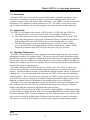
1
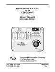
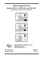
OPERATING INSTRUCTIONS
for
Models ATRT-01, ATRT-01B, and ATRT-01D
Single Phase Transformer Turns-Ratio Meter
Vanguard Instruments Co., Inc.
1710 Grevillea Court
Ontario, California 91761
TEL: 909-923-9390
FAX: 909-923-9391
May 2002
REV. 02
Model ATRT-01 (v) Operating Instructions
NOTICE
This manual applies to Models ATRT-01, ATRT-01B, and ATRT-01D; the operating procedures are
virtually the same for all models; any differences, which relate to the test units’power sources, are
clearly described within the step-by-step procedures.
SAFETY WARNINGS AND CAUTIONS
This device shall be used only by trained operators.
All transformers under test shall be off line and fully isolated
Do not Service or Test alone.
Do not perform test procedures or service unless another person is also present who is capable of
rendering aid and resuscitation.
Do Not Modify Test Equipment
Because of the added risk of introducing additional or unknown hazards, do not install substitute
parts or perform any unauthorized modification to any Model ATRT-01 Test unit. To ensure that
all designed safety features are maintained, it is recommended that repairs be performed only by
Vanguard Instrument Co. factory personnel or by an authorized repair service. Unauthorized
modifications can cause serious safety hazards and will nullify the manufacturer's warranty.
Follow Exact Operating Procedures
Any deviation from procedures described in this operator’s manual may create one or more safety
hazards, damage the ATRT-01 or the test transformer, or cause errors in the test results; VIC
assumes no liability for unsafe or improper use of the ATRT-01.
Rev 02
May 02, 2002
1
Model ATRT-01 (v) Operating Instructions
Table of Contents
1.0 Introduction ............................................................................................................................4
2.0 Applicability ...........................................................................................................................4
3.0 Operating Configuration .........................................................................................................4
4.0 Principle of Operation .............................................................................................................5
5.0 Specifications..........................................................................................................................5
6.0 Cable Marking and Identification: ...........................................................................................6
7.0 ATRT-01 Operating Controls And Indicators..........................................................................7
8.0 ATRT-01B Operating Control And Indicators.........................................................................8
9.0 ATRT-01D Control And Indicators.........................................................................................9
10.0 ATRT-01 Power Switch Configurations................................................................................10
10.1 ATRT-01 Power Turn On/Off ...........................................................................................10
10.2 ATRT-01B Power Turn On/Off.........................................................................................10
10.3. ATRT-01D Power Turn On/Off .......................................................................................10
11.0 ATRT-01B Charger Indicator ...............................................................................................10
12.0 ATRT-01 LCD Control.........................................................................................................10
12.1. Contrast Control...............................................................................................................10
12.2. Display Back-light Control...............................................................................................10
13.0 ATRT-01 RS-232C Computer-Control port ..........................................................................10
14.0 IBM PC Transformer Analysis Software ...............................................................................10
15.0 ATRT-01 Battery replacement ..............................................................................................11
15-1. ATRT-01B Battery Replacement .....................................................................................11
15-2. ATRT-01D Battery Replacement....................................................................................11
16.0 DISPLAY and MENU DESCRIPTIONS ..............................................................................12
16-1 Start-Up Menu..................................................................................................................12
17.0 Test Transformer Selection ...................................................................................................15
18.0 Transformer Voltage Selection..............................................................................................16
19.0 Transformer Voltage Data Entry Menu .................................................................................17
20.0 Start Test Menu.....................................................................................................................19
21.0 Transformer Turns-Ratio Test Result Display .......................................................................20
22.0 Three Phase Transformer Test Cable Connection Display .....................................................21
23.0 Set Time and Date.................................................................................................................22
24.0 Enable Computer Interface....................................................................................................23
25.0 Step-by-Step Turns Ratio Testing Procedures .......................................................................24
25-1 Single-Phase Transformer Test Procedure.........................................................................24
25-2 Single-Phase Transformer Test Procedure using nameplate voltages .................................25
25-3. Three-Phase Transformer Test Procedure using nameplate voltages................................26
25-4 ATRT-01 Quick-Test Mode..............................................................................................28
25-5 Test Single Phase Transformer Using Preset Voltage Table ..............................................28
Rev 02
May 02, 2002
2
Model ATRT-01 (v) Operating Instructions
List of Tables
Table 5-1. Model ATRT-01 (v) Turns-Ratio Meter Specifications .................................................5
Table 5-2: ATRT-01, ATRT-01B, and ATRT-01D Cable Set .........................................................6
Table 6-1. Cable Markings and Identification .................................................................................6
Table 25-1. Single-Phase Transformer Test Procedure. ................................................................24
Table 25-2. Single-Phase Transformer Test (with name plate voltages) Procedure. ......................25
Table 25-3. Three-Phase Transformer Test Procedure..................................................................26
List of Figures
Figure 7-0. Model ATRT-01 Front-Panel Controls, Indicators, and Connectors .............................7
Figure 8-0. Model ATRT-01B Front-Panel Controls, Indicators, and Connectors...........................8
Figure 9-0. Model ATRT-01D Front-Panel Controls, Indicators, and Connectors ..........................9
Figure 16-0 Start-up menu ............................................................................................................12
Figure 16-1 ATRT-01 Menu Diagram...........................................................................................13
Figure 17-0 Transformer Selection menu ......................................................................................15
Figure 18-0. Nameplate Voltage Selection Menu .........................................................................16
Figure 19-1. H-Winding Voltage Entry Display ............................................................................17
Figure 19-2. H-Winding Voltage Entry Display ............................................................................17
Figure 19-3. X-Winding Voltage Entry Display ............................................................................17
Figure 19-4. X-Winding Voltage Entry Display ............................................................................17
Figure 20-0. Start Test Screen......................................................................................................19
Figure 21-0. Test Result Display...................................................................................................20
Figure 22-0. Cable Connection Display........................................................................................21
Figure 23-0. Time and Date Display ............................................................................................22
Figure 24-0. Select Computer Interface Display ..........................................................................23
Figure 25-4 Quick Test Menu .......................................................................................................28
Figure 25-5A Preset Voltage Menu...............................................................................................28
Figure 25-5B Test Result Menu ....................................................................................................28
Rev 02
May 02, 2002
3
Model ATRT-01 (v) Operating Instructions
1.0 Introduction
The Model ATRT-01 is a microprocessor-based, field-portable, automatic, transformer, turnsratio test meter designed for on-site measuring of: turns ratios, winding polarity, and no-load
excitation currents of single and 3-phase utility transformers. The ATRT-01 can also test potential
transformers (PTs) and primary current transformers (CTs). The ATRT-01 may not test some
types of donut transformers (i.e., toroidal windings), since its not designed for that application.
2.0 Applicability
The ATRT-01 is available in three models: ATRT-01 (basic), ATRT-01B, and ATRT-01D.
a. The basic ATRT-01 is a line-powered 120/240 V ac (selectable), 50/60Hz unit.
b. The ATRT-01B is powered by a rechargeable lead-acid-gel battery cell. An ATRT-01B
with a fully charged battery will provide a minimum 0f 4 hours of continuous operation. A
built-in charger allows the ATRT-01B’s battery to be recharged while it is testing.
c. The ATRT-01D is powered by 6 D-cell batteries (no ac is used). To conserve battery
power, the ATRT-01D will automatically turn off after sitting idle for 1 minute. A fully
charged set of batteries in the ATRT-01D provides power for up to 200 tests.
3.0 Operating Configuration
The ATRT-01 tests transformer ratio by applying an excitation voltage to primary (H) windings
and monitors secondary (X) winding voltage. The users can also test 3-phase transformers using
the ATRT-01. The user is required to connect the H and X cable leads to the appropriate windings
for each phase. Since the ATRT-01 test lead connections to the (3-phase) transformer bushings are
different for each phase, the ATRT-01 simplifies this procedure by displaying hook-up instructions
on the LCD screen as testing progresses.
The ATRT-01 detects test-lead hook-ups for errors before a test: The ATRT-01 applies a lowlevel test voltage (300 mV) across the winding being tested and senses the induced secondary
voltages. Any time an induced voltage is greater than the applied excitation voltage, it's detected as
a hookup error. If a cross-connection error is detected, the ATRT-01 aborts the test and displays:
“Hook-Up Error." But, if no hookup error is detected, the ATRT-01 applies a full 40-volt (20-volt
for ATRT-01B/-01D) test voltage to the transformer being tested and the winding (voltage) ratio is
displayed. Excitation current (in milliamperes) and winding polarity are also displayed.
The ATRT-01 lets users enter nameplate voltages for the specified turns-ratio calculation. From
this calculated turns-ratio, the ATRT-01 will calculate and display the percentage of difference
(based on the difference between the calculated and measured values).
A built-in RS-232C port allows the ATRT-01 to interface with an IBM PC. Transformer-testing
program software, supplied with each ATRT-01, runs on an IBM Windows? -based computer and
lets users control the ATRT-01 from a computer in the field. With a computer, users can run a test
and save the test results in the field, then recall the test later in an office to generate a test report.
Since data are stored in an ASCII format, test results can be exported into any database desired.
Rev 02
May 02, 2002
4
Model ATRT-01 (v) Operating Instructions
4.0 Principle of Operation
The ATRT-01 measures transformer turns ratio by applying a test voltage across the (H) winding
and sensing induced voltage on the secondary (X) winding. (For safety, testing is always done in a
step-down transfer, regardless of the transformer’s actual use.) There's no load on windings during
testing, so measured voltage ratio is virtually the same as the winding turns ratio. The ATRT-01
measures turns ratios in a range from 0.8 to 15,000. Excitation current (via H leads) is measured
for reference and ranges from 0.0 to 2,000 mA (0 to 200 milliamperes for ATRT-01B and ATRT01D). Winding polarity is displayed as "+" (in phase) or "-" (out of phase). The ATRT-01
calibrates its own sensing circuits before each test; therefore, calibration by the operator is not
required.
5.0 Specifications
Model ATRT-01(v) specifications are listed below in Table 5-1
Table 5-1. Model ATRT-01 (v) Turns-Ratio Meter Specifications
(Unless otherwise indicated, each specification is the same for all three ATRT-01 models.)
Type
Portable, Automatic, Single-Phase Transformer Turns-Ratio Meter
Size (inches)
12 L by 8 W by 9 H
Weight (pounds)
ATRT-01: 8, ATRT-01B: 9.5, ATRT-01D: 9.5
Turns Ratio-Measuring Ranges
0.800 to 15,000.00
Turns-Ratio Accuracy
0.8-999: ? 0.1 %
1,000-1,499: ? 0.2 %
1,500-1,999: ? 1.0 %
2,000-15,000: ? 2.0%
Calibration
Self Calibrating; No operator calibration required
Excitation Voltage
ATRT-01: 40 Volts ac, ATRT-01B/ATRT-01D: 20 Volts ac
Excitation Current
ATRT-01: 2 amps, ATRT-01B/ATRT-01D: 0 to 200 milliamperes
Current Accuracy
? 2 % of Reading (? 1 Digit)
Winding Polarity
Displayed on LCD screen
Display
LCD: 20 Characters wide by 4 Lines, viewable in bright sunlight
Serial Interface
RS-232C, 19200 baud, 8 data bits, 2 start bits, 1 stop bit
Temperature
? Operating: -20 ?C to 55 ?C
Warranty
One-Year on Parts and Labor
Rev 02
May 02, 2002
5
? Storage: -40 ?C to 65 ?C
Model ATRT-01 (v) Operating Instructions
Table 5-2: ATRT-01, ATRT-01B, and ATRT-01D Cable Set
Item
Description
1
Test-Lead Cable, 15-foot
Single-Phase Connections
Power Cord (Note 1)
RS-232C Cable
2
3
Qty
1
1
1
Note:
1. The ATRT-01D requires no power cord.
2. A Canvas Cable-Carrying Bag is included with the cable set.
6.0 Cable Marking and Identification:
Both H and X cable test leads are terminated with heavy-duty battery clips. Test cables are
identified as follows:
Table 6-1. Cable Markings and Identification
Test Cable Name
H Cables
X Cables
Transformer Terminals
H
X
Rev 02
May 02, 2002
6
Clip Color
Red
Black
Identification
H1, H2
X1, X2
Model ATRT-01 (v) Operating Instructions
7.0 ATRT-01 Operating Controls And Indicators
Figure 7-0. Model ATRT-01 Front-Panel Controls, Indicators, and Connectors
Fig. 7-0 Index
1
Panel Markings
Functional Description
RS-232C
Computer-Interface port, 9-pin, female DB type
connector; RS-232C interface port allows ATRT-01
to interface with an IBM computer. Data rate is set to
19,200 baud, 1 start bit, 8 data bits, 2 stop bits, and
no parity bit. Connector pin functions are:
PIN SIGNAL
2
Tx
3
Rx
5
Gnd
LCD screen: 4 line by 20 character; back-lighted,
sunlight readable; Displays menus, test results, and
status readouts.
High and Low voltage connector, 16-pin male.
Input power connector and fused power switch with
third-wire safety ground.
2
None (display)
3
4
None
120/220Vac, 1A, 50/60Hz
5
None (Keypad)
Pushbutton operating controls, 16-keys.
Rev 02
May 02, 2002
7
Model ATRT-01 (v) Operating Instructions
8.0 ATRT-01B Operating Control And Indicators
Figure 8-0. Model ATRT-01B Front-Panel Controls, Indicators, and Connectors
Fig. 8-0
Index
Panel Markings
Functional Description
1
RS-232C
2
None (display)
3
4
None (H & X)
120/220Vac, 1A,
50/60Hz
Computer-Interface port, 9-pin, female DB type connector; This
RS-232C interface allows ATRT-01B to interface with an
IBM computer. Data rate is set to 19,200 baud, 1 start bit, 8 data
bits, 2 stop bits, and no parity bit.
PIN
SIGNAL
2
Tx
3
Rx
5
Gnd
LCD: 4 line by 20 character screen; backlighted, sunlight
readable; Displays menus, test results, and status readouts.
High voltage and Low voltage connector, 16-pin male.
Input power connector with third-wire safety ground.
5
6
None (Keypad)
POWER
Pushbutton operating controls, 16-keys.
Power Switch, Momentary contact.
Rev 02
May 02, 2002
8
Model ATRT-01 (v) Operating Instructions
9.0 ATRT-01D Control And Indicators
Figure 9-0. Model ATRT-01D Front-Panel Controls, Indicators, and Connectors
Fig. 9-2,
Index
1
Panel Markings
Functional Description
RS-232C
Computer-Interface port, 9-pin, female DB type connector;
This
RS-232C interface port allows the ATRT-01D to interface
with an
IBM computer. Data rate is set to 19,200 baud, 1 start bit, 8
data bits, 2 stop bits, and no parity bit.
PIN SIGNAL
2
Tx
3
Rx
5
Gnd
Liquid-Crystal Display (LCD): 4 line by 20 character screen;
backlighted, sunlight readable; Displays menus, test results,
and status readouts.
High voltage and Low voltage connector, 16-pin male.
2
None (display)
3
None (H & X
connector)
None (Keypad)
POWER
4
5
Pushbutton operating controls, 16-keys.
Power Switch, Momentary.
Rev 02
May 02, 2002
9
Model ATRT-01 (v) Operating Instructions
10.0 ATRT-01 Power Switch Configurations
10.1 ATRT-01 Power Turn On/Off
The ATRT-01 is powered by ac line voltage only. The power is turned on and off with a power
switch that is built into the power receptacle (see item 4 of Figure 7-0).
10.2 ATRT-01B Power Turn On/Off
The ATRT-01B is turned on or off by pressing POWER (see item 6 on Figure 8-0), on the front
panel, for 2 seconds, then releasing the switch.
10.3. ATRT-01D Power Turn On/Off
The ATRT-01D is turned on or off by pressing the POWER switch (see item 5 on Figure 9-0), on
the front panel, for 2 seconds, then releasing the switch.
11.0 ATRT-01B Charger Indicator
The CHARGE indicator is an LED that lights while the ATRT-01B battery is charging.
12.0 ATRT-01 LCD Control
12.1. Contrast Control
To Darken the LCD display, press and hold the “? Contrast” switch for two seconds; to lighten
the LCD display, press and hold the “? Contrast” switch for two seconds.
12.2. Display Back-light Control
The ATRT-01 display is back-lighted. This light turns off after 30 seconds of operation to
conserve power. To re-light the display, press any key on the keypad.
13.0 ATRT-01 RS-232C Computer-Control port
The ATRT-01 can be controlled remotely via an RS-232C port. The ATRT-01 computer control
must be enabled before it can be controlled via the RS-232C port. (Refer to paragraph 24.0 for
procedures to enable the interface control.)
14.0 IBM PC Transformer Analysis Software
IBM PC Transformer Analysis Software is delivered with each ATRT-01. This software allows
the user to test transformer turns ratio via a PC. Test results may be saved and run later in a shop
or an office environment. Such test-result records may also be saved in any user-specified database
or archival records.
Rev 02
May 02, 2002
10
Model ATRT-01 (v) Operating Instructions
15.0 ATRT-01 Battery replacement
15-1. ATRT-01B Battery Replacement
Replace the ATRT-01B battery with the following: Panasonic part number LC-R122R2PU.
Note
A rechargeable lead-acid battery powers the ATRT-01B. A fully charged ATRT-01B can be
continuously operated for 6 hours. A built-in charger lets the unit to be used during charging.
Plugging the ATRT-01B into an ac power outlet after the battery is fully charged will not damage
the battery. It is recommended that the ATRT-01B be plugged into an ac outlet when it’s not in
use.
15-2. ATRT-01D Battery Replacement
Replace ATRT-01D batteries with six standard Alkaline D-cell batteries.
Rev 02
May 02, 2002
11
Model ATRT-01 (v) Operating Instructions
16.0 DISPLAY and MENU DESCRIPTIONS
This section describes the operating menus of the ATRT-01.
16-1 Start-Up Menu
1. TEST XFMR
04/12/00
2. SETUP
13:06:02
3. CALCULATOR
Figure 16-0 Start-up menu
a. Description: The start-up menu lets the user test a transformer, set-up time, select computer
interface, or use the calculator to manually enter voltage data for transformer ratio calculation.
b. Origin: The Start-up menu first displays after power is applied to ATRT-01.
c. Action Options:
Press key 1 to initiate a transformer test.
Press key 2 to set clock or select computer interface.
Press key 3 to calculate transformer turns ratio.
Note:
1. Real time and date is shown on top left of LCD screen.
2. See section 12.1 for LCD contrast control.
3. See section 12.2 for LCD back light control.
Rev 02
May 02, 2002
12
Model ATRT-01 (v) Operating Instructions
Figure 16-1 ATRT-01 Menu Diagram
Rev 02
May 02, 2002
13
Model ATRT-01 (v) Operating Instructions
Rev 02
May 02, 2002
14
Model ATRT-01 (v) Operating Instructions
17.0 Test Transformer Selection
XFMR CONFIGURATION:
1.SNGL PHS
2.dT-Y
2.Y-dT
4.dT-dT
5.Y-Y
Figure 17-0 Transformer Selection menu
a. Description: This menu allows the user to select a particular transformer to be tested. If the user
selects a three-phase transformer, the ATRT-01 will display hookup instructions (ATRT-01 cables
to the transformer terminal bushing) for phases A, B, and C.
b. Origin: XFORMER CONFIGURATION menus display as a result of pressing key 1 from the
start-up menu (see Figure 16.0).
c. Action Option: Press key 1, 2, 3, 4, or 5, depending upon the transformer configuration to be
tested. Press STOP to return to the start-up menu.
Rev 02
May 02, 2002
15
Model ATRT-01 (v) Operating Instructions
18.0 Transformer Voltage Selection
XFMR NAME PLATE VLTG
1. YES
2. NO
Figure 18-0. Nameplate Voltage Selection Menu
a. Description: This menu allows the operator to use the transformer nameplate voltages to derive
a calculated turns ratio. This calculated turns ratio is then used to compare with the measured turns
ratio, which produces an error-difference percentage.
b. Origin: This menu is displayed after the operator selects the transformer type to be tested.
c. Action Option: Press key 1(yes) to use the calculated ratio in the test results. Press key 2 (no) to
bypass this option.
Rev 02
May 02, 2002
16
Model ATRT-01 (v) Operating Instructions
19.0 Transformer Voltage Data Entry Menu
ENTER H WINDING
NAME-PLATE VOLTAGE:
V
Figure 19-1. H-Winding Voltage Entry Display
ENTER H WINDING
NAME-PLATE VOLTAGE:
7200V
Figure 19-2. H-Winding Voltage Entry Display
ENTER X WINDING
NAME-PLATE VOLTAGE:
V
Figure 19-3. X-Winding Voltage Entry Display
ENTER X WINDING
NAME-PLATE VOLTAGE:
480V
Figure 19-4. X-Winding Voltage Entry Display
Rev 02
May 02, 2002
17
Model ATRT-01 (v) Operating Instructions
a. Description: This menu allows the user to enter the H and X voltages of the transformer to be
used in the turns-ratio calculation. The user must enter the transformer nameplate line voltages.
b. Origin: H and X voltage data entry menu will appear if the user select YES (key #1) on the
Voltage-selection screen (see Figure 18-0).
c. Action Option: Press keys 0 thru 9 to enter transformer voltages. Press ENTER to confirm
voltage entry. Press CLEAR key to re-enter input.
Rev 02
May 02, 2002
18
Model ATRT-01 (v) Operating Instructions
20.0 Start Test Menu
SINGLE PHASE XFORMER
“START” TO RUN TEST
OR
“STOP” TO ABORT
Figure 20-0. Start Test Screen
a. Description: This menu allows the user to start or abort a test.
b. Origin: After the user enters the nameplate voltages (see Figure 19-4) or selects NO on the
“XFMR NAME PLATE VLTG Screen” (see Figure 18-0).
c. Action Option: Press START to start the test and press STOP to abort the test.
Rev 02
May 02, 2002
19
Model ATRT-01 (v) Operating Instructions
21.0 Transformer Turns-Ratio Test Result Display
RATIO
+1.003
mA
0002
%DIFF
0.3
Figure 21-0. Test Result Display
a. Description: The ATRT-01 displays the transformer turns ratio, excitation current (in
milliamps), and turns-ratio error percentage. A typical turns-ratio test-result screen is shown on
Figure 21-0, above.
Note
Ratio displayed: 1.003
Polarity displayed: “+” (in phase)
Excitation current: 2 ma
Percentage error: 0.3 %
b. Origin: This screen is displayed after the user presses START from the Start Test Menu.
c. Action Option: Press any key to return to the start-up menu (Figure 16-0).
Rev 02
May 02, 2002
20
Model ATRT-01 (v) Operating Instructions
22.0 Three Phase Transformer Test Cable Connection Display
CABLE PHS-A XFMR
X1, X2
to
X1, X0
H1, H2
to
H1, H3
“START” TO RUN TEST
Figure 22-0. Cable Connection Display
a. Description: If a user is using the ATRT-01 to test a three-phase transformer, the transformer is
tested one phase at a time. The user must connect the ATRT-01’s H1-H2 and X1-X2 cable leads to
the appropriate windings to produce turns-ratio readings for phases A, B, and C. The ATRT-01
displays the lead-to-bushing connection instruction (for each phase). By following the connection
instruction, the ATRT-01 will lead the user through phase A, B, and C testing.
This feature reduces the probability of any hook-up error in the field.
b. Origin: Select a three-phase transformer from the XFMR CONFIGURATION menu (see Figure
17-0).
c. Action Option: Connect the ATRT-01 test leads to the transformer bushings, then press START
to run test.
Rev 02
May 02, 2002
21
Model ATRT-01 (v) Operating Instructions
23.0 Set Time and Date
ENTER
MM-DD-YY HH:MM:SS
Figure 23-0. Time and Date Display
a. Description: The ATRT-01 has a real-time clock powered with a back-up battery. The ATRT01 displays the current time and date in the upper right of the start-up menu screen (see Figure 160).
b. Origin: Press key 2 (SET UP) on the start-up menu (Figure 16-0) and press 1 (SET TIME).
c. Action Option: Enter month, day, year, hour, minute, and second using key 0-9.
Rev 02
May 02, 2002
22
Model ATRT-01 (v) Operating Instructions
24.0 Enable Computer Interface
COMPUTER ITF MODE
*** CAUTION! ***
CABLE MAY HAVE VLTG
“STOP” TO ABORT
Figure 24-0. Select Computer Interface Display
a. Description: ATRT-01 testing can be remotely controlled via an IBM-compatible PC through an
RS-232C port. In this mode, the Transformer Analysis software provided with the ATRT-01 is
used to test transformer windings.
b. Origin: On the Start-up Menu (see Figure 16-0), press key 2 (SET UP); then, on the next
display, press key 2 (COMPUTER CONTROL) to show the COMPUTER ITF MODE display (the
ATRT-01 testing remains under computer control for as long as this screen displays).
c. Action Option: Press STOP to abort computer control and return to the Start-up menu.
Rev 02
May 02, 2002
23
Model ATRT-01 (v) Operating Instructions
25.0 Step-by-Step Turns Ratio Testing Procedures
25-1 Single-Phase Transformer Test Procedure
Table 25.1 shows the steps to test a single-phase transformer.
Table 25-1. Single-Phase Transformer Test Procedure.
STEP
DESCRIPTION
DISPLAY
ACTION
1. TEST XFMR
04/12/00
2. SETUP
13:06:02
3. CALCULATOR
XFMR CONFIGURATION:
1. SNGL PHS 2. dT-Y
3. Y-dT
4.dT-dT
5. Y-Y
Press key 1
Select not to use
transformer name plate
voltage
XFMR NAME PLATE VLTG
1. YES
2. NO
Press key 2.
4
Start test
Press START key
5
Display ratio, excitation
current
SINGLE PHASE XFMR
“START” TO RUN TEST
OR
“STOP” TO ABORT
RATIO mA %DIFF
+1.000 0002
1
Initiate Transformer Test
2
Select Single Phase
Transformer
3
Rev 02
May 02, 2002
24
Press key 1.
None
Model ATRT-01 (v) Operating Instructions
25-2 Single-Phase Transformer Test Procedure using nameplate voltages
Table 25.2 shows the steps to test a single-phase transformer with transformer name plate
voltages.
Table 25-2. Single-Phase Transformer Test (with name plate voltages) Procedure.
STEP
DESCRIPTION
1
Initiate Transformer Test
2
Select Single Phase
Transformer
3
Select to use transformer
name plate voltage
4
Enter H line voltage
5
Confirm H line voltage
6
Enter X line voltage
7
Confirm X voltage
8
Start Test
9
Display ratio, excitation
current, and percentage
error.
DISPLAY
1. TEST XFMR 04/12/00
2. SETUP
13:06:00
3. CALCULATOR
XFMR CONFIGURATION
1. SNGL PHS
2. dT-Y
3. Y-dT
4.dT-dT
5. Y-Y
XFMR NAME PLATE VLTG
1. YES
2. NO
ENTER H WINDING
NAME-PLATE VOLTAGE
V
ENTER H WINDING
NAME-PLATE VOLTAGE
7200 V
ENTER X WINDING
NAME-PLATE VOLTAGE
V
ENTER X WINDING
NAME-PLATE VOLTAGE
480 V
SINGLE PHASE XFMR
“START” TO RUN TEST
OR
“STOP” TO ABORT
RATIO mA %DIFF
+15.003 01.00 0.02
Rev 02
May 02, 2002
25
ACTION
Press key 1
Press key 1.
Press key 1.
Use keys 0-9
Press ENTER
Use keys 0-9
Press ENTER
Press START
None
Model ATRT-01 (v) Operating Instructions
25-3. Three-Phase Transformer Test Procedure using nameplate voltages
Table 25.3 shows the steps to test a three-phase transformer.
Table 25-3. Three-Phase Transformer Test Procedure.
STEP
1
DESCRIPTION
Initiate Transformer Test
2
Select Delta to Y Phase
Transformer
3
Select to use transformer name
plate voltage
4
Enter H line voltage
5
Confirm H voltage
6
Enter X line voltage
7
Confirm X voltage
8
ATRT-01 display phase A cable
connection
9
Start phase A test
10
Observe phase A test results
11
ATRT-01 display phase B cable
connection
12
Start phase B test
DISPLAY
1. TEST XFMR
04/12/00
2. SETUP
13:06:00
3. CALCULATOR
XFMR CONFIGURATION
1. SNGL PHS
2. dT-Y
3. Y-dT
4.dT-dT
5. Y-Y
XFMR NAME PLATE VLTG
1. YES
2. NO
ENTER H WINDING
NAME-PLATE VOLTAGE
V
ENTER H WINDING
NAME-PLATE VOLTAGE
7200 V
ENTER X WINDING
NAME-PLATE VOLTAGE
V
ENTER X WINDING
NAME-PLATE VOLTAGE
480 V
CABLE PHS-A XFMR
X1, X2
to
X1, X0
H1, H2
to
H1, H3
“START” TO RUN TEST
CABLE PHS-A XFMR
X1, X2
to
X1, X0
H1, H2
to
H1, H3
“START” TO RUN TEST
RATIO mA %DIFF
+15.003 001 0.02
“ENTER” TO CONTINUE
CABLE PHS-B XFMR
X1, X2
to
X2, X0
H1, H2
to
H2, H1
“START” TO RUN TEST
CABLE PHS-B XFMR
X1, X2
to
X2, X0
H1, H2
to
H2, H1
“START” TO RUN TEST
Rev 02
May 02, 2002
26
ACTION
Press key 1
Press key 2
Press key 1
Use keys 0-9
Use keys 0-9
Press ENTER
Connect cables
Press START
None
Connect cables
Press START
Model ATRT-01 (v) Operating Instructions
STEP
13
DESCRIPTION
Observe phase B test results
14
ATRT-01 display phase C cable
connection
15
Start phase C test
16
Observe phase C test results
DISPLAY
RATIO mA %DIFF
+15.003 001
0.02
+15.015 001
0.10
“ENTER” TO CONTINUE
CABLE PHS-B XFMR
X1, X2
to
X3, X0
H1, H2
to
H3, H1
“START” TO RUN TEST
CABLE PHS-C XFMR
X1, X2
to
X3, X0
H1, H2
to
H3, H2
“START” TO RUN TEST
RATIO mA %DIFF
+15.003 001
0.02
+15.015 001
0.10
+15.000 001
0.00
Rev 02
May 02, 2002
27
ACTION
None
Connect cables
Press START
None
Model ATRT-01 (v) Operating Instructions
25-4 ATRT-01 Quick-Test Mode
The Quick-Test mode allows the user to measure transformer turn ratio with a single button
command. To initiate the test, press and hole the “START” key for one second then release. The
ATRT-01 will display the message below on the LCD.
“QUICK TEST”
HOLD START KEY UNTIL
BEEP FOR QUICK TEST
Figure 25-4 Quick Test Menu
25-5 Test Single Phase Transformer Using Preset Voltage Table
This special mode allows the user to quickly test a single phase transformer ratio and compare it’s
reading against a name plate voltage. There are 46 transformer name plate voltages pre-program in
the ATRT-01. To access this mode, press “CLEAR” key from the main menu (Fig 16-0); the
ATRT-01 will display the following message:
? ? SCROLL TO SELECT
“START” TO RUN TEST
H 2,400
X
240
Figure 25-5A Preset Voltage Menu
To select different name plate voltages, use the up or down arrow keys “? ? ”. To initiate a test,
press the “START” key. A typical test result is shown below:
M-RATIO= +10.001
ERROR= 0.11%
PASS TTR TEST
2,400/240 R=10.00
Figure 25-5B Test Result Menu
Note:
In order to have the “PASS TTR TEST” message display, the reading error should be less or equal
to 0.5% and the winding should be in phase.
Rev 02
May 02, 2002
28
Model ATRT-01 (v) Operating Instructions
APPENDIX A- TABLE OF TEST CONFIGURATION & CALCULATION FORMULAS
Rev 02
May 02, 2002
29
1710 Grevillea Court, Ontario, CA 91761, USA
Phone: 909-923-9390
Fax: 909-923-9391
Website: http//www.vanguard-instruments.com
Rev 01
May 02, 2000