1
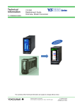
Technical
Information
TI 01B08A02-08EN
YS1000
Replacement Guide
SLPC → YS1700 User Program Conversion
l
tiona
Func cement
n
Enha
The contents of this Technical Information are subject to change without notice.
Yokogawa Electric Corporation
2-9-32, Nakacho, Musashino-shi, Tokyo, 180-8750 Japan
TI 01B08A02-08EN
©Copyright June 2014
1st Edition Jun.13, 2014
2
Contents
Introduction....................................................................................................... 3
1. Old model conversion flow chart............................................................... 4
2. Schematic of SLPC conversion.................................................................. 5
3. SLPC conversion procedure....................................................................... 5
4. Precautions.................................................................................................18
5. Reference documentation.........................................................................18
Revision Information......................................................................................... i
TI 01B08A02-08EN 1st Edition: June 2014(YK)
All Rights Reserved. Copyright © 2014, Yokogawa Electric Corporation
TI 01B08A02-08EN
2014.06.13
3
Introduction
This manual describes how to read user programs and parameters from an SLPC and
convert them for the YS1700.
Be sure to check data and operations after conversion.
●Documentation for replacement
Name
YS1000 Series Replacement Guide
Overview, Model Conversion
No.
TI 01B08A02-05EN
YS1000 Series Replacement Guide
Installation and Wiring
TI 01B08A02-06EN
YS1000 Replacement Guide
YS170 → YS1700 User Program Conversion
TI 01B08A02-07EN
YS1000 Replacement Guide
SLPC → YS1700 User Program Conversion
TI 01B08A02-08EN
Description
Please read me first.
This manual describes the overview,
model conversion.
This manual describes the compatibility
of installation and wiring with YS100,
YS80, EBS, I, EK, HOMAC, and 100
line.
This manual describes how to read
user programs and parameters from
the YS100 and convert then to YS1000
data.
This manual describes how to read
user programs and parameters from the
SLPC and convert then to YS1000 data.
■ Notice
• The contents of this manual are subject to change without notice as a result of continuing
improvements to the instrument’s performance and functions.
• Every effort has been made to ensure accuracy in the preparation of this manual. Should
any errors or omissions come to your attention, however, please inform Yokogawa
Electric’s sales office or sales representative.
• Under no circumstances may the contents of this manual, in part or in whole, be
transcribed or copied without our permission.
■ Trademarks
• Our product names or brand names mentioned in this manual are the trademarks or
registered trademarks of Yokogawa Electric Corporation (hereinafter referred to as
YOKOGAWA).
• Ethernet is a registered trademark of XEROX Corporation in the United States.
• We do not use the TM or ® mark to indicate these trademarks or registered trademarks
in this user’s manual.
• All other product names mentioned in this user’s manual are trademarks or registered
trademarks of their respective companies.
TI 01B08A02-08EN
2014.06.13
4
1. Old model conversion flow chart
Start up YSS1000
Select “YS1000 Configuration Function” in the Select YSS1000 Function window.
The Basic window is displayed.
Select one of the following tasks from the menu “Convert”.
Convert
YSS20 file
Convert
by reading
directly from
YS100 file
Convert from
SLPC user ROM
►Section 2.13.1
►Section 2.13.2
►Section 2.13.3
Read
YSS20 file
Upload
All YS100
SLPC
►Refer to YSS1000 Setting Software /
YS1700 Programmable Function
User’s Manual
Convert data.
No
User program
Yes
Check program.
No error
Error
Review user program.
►Chapter 3 User Program Creation Guide
Review parameters.
►2.4 Setting Parameters, Control Period,
K Register, and P/X/Y Register
Save the data to a file.
►2.11.7 Saving Files under a Different Name
Download to YS1000
►2.7 Downloading Data
Direct input
No
Yes
Set input specifications.
►User’s Manual of respective controllers
for adjustment of direct input (temperature,
resistance, frequency)
User program
No
Yes
Debug user program.
When in YS1700 programmable mode only
►2.10.2 Monitoring Register Data
►2.10.4 Monitoring Control Module Function Blocks
►2.10.5 Monitoring Modules
►2.10.1 Monitoring Tuning Data
Perform tuning.
Check operation.
Operate.
TI 01B08A02-08EN
2014.06.13
5
2. Overview of SLPC conversion
3. SLPC conversion procedure
3.1 Entering SLPC parameters on the parameter sheet
3.2 Reading ROM data
3.3 Starting the YSS1000
3.4 Converting ROM data and checking converted results
3.5 Checking and entering system data
3.6 Saving files
3.7 Comparing programs
3.8 Checking programs
3.9 Checking and entering parameters
3.10 Downloading to the YS1000
3.11 Checking operation (debugging programs)
TI 01B08A02-08EN
2014.06.13
6
3.1 Entering SLPC parameters on the parameter sheet
After writing down SLPC parameters on the parameter sheet, enter them accordingly.
Use the SLPC-YS1700 parameter sheet found in
section 11.4, "SLPC-YS1700 Data Conversion
Parameter Sheet" of the YSS1000 Setting
Software/YS1700 Programmable Function
user's manual (IM 01B08K02-02EN).
3.1.1 List of parameters requiring special handling
The following is a list of parameters that require conversion or other
special consideration.
SLPC Parameter
YS1700 Parameter Before Conversion Aftger Conversion Remarks
F01~F11
FX101~FX111
0.0~100.0
G01~G11
FX201~FX211
0.0~100.0
H01~H11
GXI101~GXI111
-25.0~125.0
I01~I11
GXO101~GXO111 -25.0~125.0
L01~L11
GXI201~GXI211
-25.0~125.0
M01~M11
GXO201~GXO211 -25.0~125.0
P30~P39
PGO101~PGO110 -25.0~125.0
STC
IP1,IP2
OS1,OS2
DP1,DP2
MODE1
MODE2
MODE4
STC
IP1,IP2
OS1,OS2
SCDP1,SCDP2
START
CMOD1
BMOD1
OFF/0/1/2
0/1
0/1/2/3
1~4
0/1
0/1/2
0/1
Divide the setting value of SLPC by 100 and
calculate to three digits after the decimal point.
Divide the setting value of SLPC by 100 and
0.000~1.000
calculate to three digits after the decimal point.
Divide the setting value of SLPC by 100 and
-0.250~1.250
calculate to three digits after the decimal point.
Divide the setting value of SLPC by 100 and
-0.250~1.250
calculate to three digits after the decimal point.
Divide the setting value of SLPC by 100 and
-0.250~1.250
calculate to three digits after the decimal point.
Divide the setting value of SLPC by 100 and
-0.250~1.250
calculate to three digits after the decimal point.
Divide the setting value of SLPC by 100 and
-0.250~1.250
calculate to three digits after the decimal point.
OFF/DISP/ON/ATSTUP OFF:OFF/0:DISP/1:ON/2:ATSTUP
0.000~1.000
STATIC/DYNAM
0:STATIC/1:DYNAM
ZERO/MIN/MED/MAX
0:ZERO/1:MIN/2:MED/3:MAX
#.####~#####
1:##.###/2:###.##/3####.#/4:#####
M-COLD/AUT
0:M-COLD/1:AUT
-/CAS/CMP
0:-/1:CAS/2:CMP
BUM/BUA
0:BUM/1:BUA
TI 01B08A02-08EN
2014.06.13
7
3.2 Reading ROM data
ROM reader
– Use universal program MODEL1882 and MODEL1883
binary format.
– Device selection: 28 Pin: MBM27C64, 24 Pin: MBM2716
» Minato Electronics Corp.
» URL:http://www.minato.co.jp/en/index.html
3.2.1 Before reading ROM data
Specify the startup directory.
– Specify a folder other than the default value of C:/Program Files.
» How to specify a folder:
Menu > Options > Option settings
» Ex.: Subfolders of each USER folder
TI 01B08A02-08EN
2014.06.13
8
3.2.2 Selecting a ROM device
Selecting a device
– Click Select
» Manufacturer: Fujitsu
» Device selection: 28 Pin: MBM27C64, 24 Pin: MBM2716
3.2.3 Reading and saving ROM data
Reading and saving ROM data
– Reading ROM data: Press the Read button
– Saving ROM data: Press the Save button
» Save in binary format.
TI 01B08A02-08EN
2014.06.13
9
3.3 Starting the YSS1000
Start the YSS1000
Click the YS1000 setting function link
3.4 Converting ROM data and checking the list of results
Converting ROM data
(1) Menu > Convert old model > SLPC
(2) Correct any errors that are found. Otherwise, OK.
(3) Parameters expanded from the SLPC become the defaults on the YS1700.
TI 01B08A02-08EN
2014.06.13
10
3.5 Checking and entering system data
Since it will become the YS1700-100 after conversion, you must
enter system data referencing the name plate.
(1) Enter system data referencing the YS1700 name plate
3.6 Saving files
When converting system data, follow the prompts to save files.
TI 01B08A02-08EN
2014.06.13
11
3.7 Comparing programs
Compare with the SLPC program list
3.8 Checking programs
Select Tools > Program check to run a program check.
(1) If an error occurs, check the program.
TI 01B08A02-08EN
2014.06.13
12
3.9 Checking and entering parameters (part 1)
(1) First, check the LOOP scale.
Note: This is because you cannot check matching of industrial quantities if the scales do not match.
(2) Set TAG numbers and industrial units.
3.9 Checking and entering parameters (part 2)
Set appropriate default parameters.
(1) Set screen parameters as appropriate.
TI 01B08A02-08EN
2014.06.13
13
3.9 Checking and entering parameters (part 3)
(1) Check other parameters and apply them as needed.
Note: If you find differences between the YSS1000 parameters and the parameter sheet,
apply all values from the sheet on the YSS1000.
3.10 Download on the YS1000
Connect the YS1000.
TI 01B08A02-08EN
2014.06.13
14
3.10.1 Execute the download
(1) Menu > Communication > Download all
(2) Click STOP and Execute Download all
3.11 Checking operation (debugging programs)
Be sure to review the data that was downloaded from the SLPC
to the YS1700 and converted, and check operation.
TI 01B08A02-08EN
2014.06.13
15
3.11.1 YS1700 operation modes
(1) RUN mode: Run user programs.
(2) TEST1 mode: Run user programs and simulation programs.
(3) TEST2 mode: Run user programs and simulation programs.
You can also set input signals (you can debug without wiring).
3.11.2 Debug with tuning
(1) Menu > Communication > Tuning
(2) Click TEST2, execute tuning
TI 01B08A02-08EN
2014.06.13
16
3.11.3 Description of the tuning window
Trend monitor
Register monitor
Loop
3.11.4 Debug with tuning
(1) Designate all AI, AO, DI, and DO for the register monitor.
Drag & Drop
TI 01B08A02-08EN
2014.06.13
17
3.11.4 Debug with tuning
(1) Set control registers AI and DI as needed.
(2) Confirm proper operation.
3.12 Start in RUN mode after debugging
Switch from TEST2 mode to RUN mode.
TI 01B08A02-08EN
2014.06.13
18
4 Precautions
Be sure to review the data that was downloaded
from the SLPC to the YS1700 and converted, and
check operation.
– Review is required if using the following commands.
– CSC, SSC
– ST A15(PVM1), ST A16(SVM1), ST FL32
» Reason: The display procedure on the SLPC and YS1700 differs.
User ROM conversion parameters and operational parameters
– User ROM installed in the SLPC contains user programs and initial
parameters. The tuning and other data actually used on the SLPC
is not located in the user ROM. When converting data, read the
operational parameters and ACTION switch settings from the SLPC
side panel, and record them on the parameter sheet. Set the
operational parameters that you recorded on the YSS1000. If
entering settings on the YSS1000, first enter the scale parameters.
Use the parameter sheet found in section 11.4, "SLPC-YS1700
Data Conversion Parameter Sheet."
5 Reference documentation
Software (user programs)
•
YSS1000 Setting Software/YS1700 Programmable Function
user's manual
» (IM 01B08K01-02)
– 2.13.3 Converting the User ROM Data of YS80 (SLPC)
» Describes the procedure for converting SLPC user ROM data.
– 11.4 Parameter Sheet for SLPC-YS1700 Data Conversion
» Use the parameter sheet when converting SLPC data for the
YS1700.
Reference materials
• ROM reader
» Use universal program MODEL1882 and MODEL1883
» Minato Electronics Corp.
» URL:http://www.minato.co.jp/en/index.html
TI 01B08A02-08EN
2014.06.13
i
Revision Information
Title
: YS1000 Replacement Guide
SLPC → YS1700 User Program Conversion
Manual number: TI 01B08A02-08EN
June 2014/1st Edition
Newly published
Written by
Yokogawa Electric Corporation
Published by Yokogawa Electric Corporation
2-9-32 Nakacho, Musashino-shi, Tokyo 180-8750, JAPAN