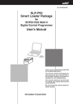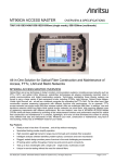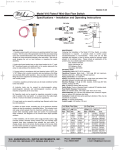
1
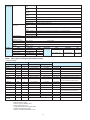
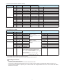
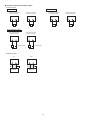
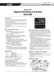
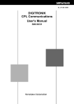
No. CP-SS-1853E
DCP552B Mark II
DIGITRONIKTM
Programmable Controller
Overview
The DIGITRONIKTM DCP552B Mark II is a high-function
programmable controller supporting two channels (up to
49 program patterns per channel) to which thermocouple,
resistance temperature detector (RTD), DC voltage, DC
current and other signals can be input.
The DCP552 Mark II supports 16 event outputs, 16 external
switch inputs and a wide range of other functions as part of
the standard specification.
Features
• Accuracy of ±0.1%FS. Easy-to-view large display
characters. Compact design.
• Any input type can be selected by console key operation.
• Easy operation aided by guidance messages.
• Up to 49 program patterns can be stored to each channel
and up to 99 segments can be programmed to each
pattern.
• Any event can be selected to each channel and set for
the 16 event outputs, and code events comprising a
combination of two or more points can be set.
• 16 external switch inputs allow the control of remote
selection of program Nos. or operation on each channel
separately or both channels simultaneously.
• CE marking-compatible
Applicable standards: EN61010-1, EN61326
Basic function blocks of DCP552B Mark II
Input 1
• Root extraction
• Linearization table
approximation
• Input bias
• Filter
• Thermocouple
• Resistance temperature
detector (RTD)
• DC current
• DC voltage
Input 2
• Thermocouple
• Resistance temperature
detector (RTD)
• DC current
• DC voltage
• O2 sensor
*2
• Root extraction
• Linearization table
approximation
• Input bias
• Filter
12 external switch inputs
•
•
•
•
RUN
HOLD
RESET
ADV
•
•
•
•
FAST
RAMP-E
AUTO/MANUAL
AT
• Program No.
• CH1 operation cancel
• CH2 operation cancel
4 external switch inputs
•
•
•
•
Control operation block
G.Soak cancel
Direct/reverse action
Autoload
O2 sensor check
• Mode transition
• PID control
• Auto-tuning
• Direct/reverse action
• ON-OFF control
• SP limit
• SP bias
Key operation
• Display selection
• Display channel
selection
• Program No.
• RUN/HOLD
• RESET
• ADV
•
•
•
•
•
•
• Current-proportional
• Voltage time-proportional
• Open-collector time-proportional
• Output change limiter
• Upper/lower limiter
• Current-proportional
• Voltage time-proportional
• Open-collector time-proportional
Output 2
16 event outputs
•
•
•
•
•
•
•
Time event
PV
SP
Deviation
MV
Code
Code w/ timer
•
•
•
•
PV
SP
Deviation
MV
•
•
•
•
•
•
•
Modes
Alarm
Segment No. code
Unique segments
Program No. code
PV rate-of-change
O2 sensor error
1, 2 auxiliary outputs
RS-485/RS-232C communications I/O
FAST
AUTO/MANUAL
AT
Program setup
Parameter setup
Memory card
operation
•
•
•
•
•
•
Output 1
• Output change limiter
• Upper/lower limiter
*1
*1
Loader communications I/O
Program
2 channels x 49 patterns x 99 segments
PID sets/output limiter sets
Events
• PV start
G.Soak
• Cycle
PV shift
• Pattern link
Repeat
•
•
•
•
•
Parameter
Variable parameters
Event configuration
PID parameter
Setup
Constant-value operation
1
*1: Option according to model No.
*2: Thermocouple, RTD, DC current and DC voltage
can be selected on models not supporting CP.
Models supporting CP become O2 sensors.
Specifications
Program
Inputs
Number of programs
49 programs x 2 channels
Number of segments
99 per program, total 2000
Segment setting system
RAMP-X: Set by set points (SP) and time
RAMP-T: Set by set points (SP) and ramp (θ)
RAMP-E: Set by set points (SP) and ∆SP per external switch input 1 pulse
Segment time
0 to 500 hours 0 minute, 0 to 500 minutes 0 second, 0.0 to 3000.0 seconds (time unit selectable)
Segment ramp
1 to 10000 U/hour, 1 to 10000 U/minute, 1 to 10000 U/second (time unit selectable)
Segment ∆SP
1 to 10000 U/1 pulse
Number of subfunctions
4000
Sub-function action
Events, PID set, output limiter set, G.Soak, PV shift, repeat
Events (16)
Set operating point corresponding to event type
PID set No.
Set 0 (continuation of previous segment), 1 to 9, A set (automatically switched) and ON-OFF control
Output limiter set
Set 0 (continuation of previous segment), 1 to 9
G.Soak
Set type (start/end points and overall) and G.Soak width 0 to 1000 U.
PV shift
-10000 to +10000 U
Repeat
Set return destination segment No. and repeat count.
PV start
Set type (rising/falling or both) for each program.
Cycle
Set cycle count for each program.
Pattern link
Set program No.0 to 49 (0: no link) for each program.
Tag
Set 8 alphanumerics or symbols for each program.
Basic time accuracy
±0.01% (segment time setting = 0, with 0.1 second delay for each repeat and cycle)
Input type
Thermocouple, resistance temperature detector (RTD), DC voltage, DC current multi-range
(See pages 6, 7.)
Sampling cycle
0.1 seconds
Input bias current
Thermocouple, DC voltage input:Max. ±1.3 µA (at peak value and reference conditions)
1 V or higher range: Max. -3 µA
Input impedance
DC current input: approx. 50 Ω (under operating conditions)
Measuring current
RTD input: Approx. 1 mA current flow from terminal A (under operating conditions)
Influence of wiring
resistance
Thermocouple, DC voltage input:Thermocouple: 0.5 µV/Ω
DC voltage (max. 1 V range): 0.5 µV/Ω
DC voltage (5 V range): 3 µV/Ω
DC voltage (10 V range): 6 µV/Ω
RTD input:Max. ±0.01%FS/Ω in wiring resistance range 0 to 10 Ω
Range of F01, F33, P01 and P33: ±0.02%FS/Ω max.
RTD input allowable
wiring resistance
• Ranges other than F01, F33, P01 and P33: 85 Ω max.
• Ranges of F01, F33, P01 and P33: 10 Ω max.
Allowable parallel
resistance
Thermocouple disconnection detection allowable parallel resistance: 1 MΩ min.
Max. allowable input
Thermocouple, DC voltage input: -5 to +15V DC
DC current input: 50 mA DC, 2.5V DC
Burnout
Detection selectable
Over-range detection
threshold
110%FS min.: Upscaled
-10%FS max.: Downscaled (Note that F50 range is not downscaled.)
Cold- junction
compensation system
Internal/external (0°C only) compensation selectable
Scaling
-19999 to +20000 U (possible in case of linear input only. Inverse scaling possible. Decimal point position
settable at any point)
Square root extraction
Possible. Dropout: 0.2 to 10.0% in case of DC current or DC voltage range
PV equalizer
(linearization table
approximation)
PV1: 9 segments (10 points set)
PV2: 9 segments (10 points set)
CP: 9 segments (10 points set)
Input bias
-1000 to +1000 U variable
Digital filter
0.0 to 120.0 seconds variable (0.0: filter OFF)
Cold-junction
compensation accuracy
±0.5°C (under standard conditions)
2
Number of inputs
External
switch inputs Types of connectable
outputs
Dry contacts (relay contact) and open-collector (current sink to ground)
Terminal voltage
(open)
8.5 V±0.5 V between common terminals (terminals
conditions)
Terminal current
(short-circuit)
Approx. 6 mA between each terminal (under operating conditions)
Allowable contact
resistance
(dry contact)
ON: 250 Ω max. (under operating conditions)
OFF: 100 kΩ min. (under operating conditions)
Voltage drop
(at open-collector ON)
2 V max. (under operating conditions)
Leakage current
(at open-collector OFF)
0.1 mA max. (under operating conditions)
Parallel connection
with other instruments
Can be connected to Azbil Corporation SDC40 and SDC10 series
Assignments (fixed)
RUN, HOLD, RESET, ADV, program No., CH1 operation cancel, CH2 operation cancel
Assignments (variable)
RAMP-E, FAST, AT, AUTO/MANUAL, G.Soak cancel, auto-load, O2 sensor check
Input sampling cycle
0.1 seconds
ON detection min.
hold time
0.2 seconds (0.4 seconds for program No.)
Upper display
Indication/
programmer
Modes
16
,
) and each input terminal (under operating
Green 5-digit, 7-segment LED
This displays PV values in the basic display state.
Item codes are displayed in the parameter setup.
Lower display
Orange 5-digit, 7-segment LED
This displays SP and output % in the basic display state.
Setting values are displayed in the parameter setup.
Program No. display
Green 2-digit, 7-segment LED
This displays program No. in the basic display state.
Segment No. display
Green 2-digit, 7-segment LED
This displays segment No. in the basic display state.
Item Nos. are displayed in parameter setup, and alarm No. is displayed when alarm occurs.
Message display
This displays output graph, deviation graph, event state and tags in the basic display state.
This displays reference messages in the parameter setup and program setup.
This displays operation details and operation results of memory card operation.
Profile display
7 orange LEDs
Displays program pattern rise, soak and fall trends.
Status displays
22 round LEDs
Modes: RUN, HLD, MAN, PRG (green)
Display details: PV, SP, OUT, TM, CYC, SYN, DEV (green), EG1, EG2 (red)
Battery voltage: BAT (red) (blinks at low voltage)
Status: AT (green)
Operation keys
18 rubber keys
Loader connector port
1 (dedicated cable with stereo miniplugs)
Program operation
modes
READY: Ready to run program (control stop/program No. selectable)
RUN: Program run
HOLD: Program hold
FAST: Program fast-forward
END: Program end
READY FAST: Ready to run and fast-forward program
AUTO: Automatic operation
MANUAL: Manual operation (output can be controlled on console)
Constant-value
operation modes
Controller
READY: Ready to run program (control stop)
RUN: Program run
AUTO: Automatic operation
MANUAL: Manual operation (output can be controlled on console)
PID controls
Proportional band (P) 0.0 to 1000.0% (0.0: ON-OFF control)
Reset time (I)
0 to 3600 seconds. 0 seconds: PD control
Rate time (D)
0 to 1200 seconds. 0 seconds: PI control
MV limit
Lower limit: -5.0 to upper limit %
Upper limit: Lower limit to +105.0%
Manual reset
0.0 to 100.0%
3
Controller
Outputs
PID controls
Direct/reverse action
switching
Auxiliary output
16 sets for program operation (9 segment unique sets + 7 sets for automatic zone
selection)
PID set selection
Segment designation/automatic zone selection can be switched by program operation.
MV change
0.1 to 110.0%/0.1 seconds
Auto-tuning
Automatic setting of PID value by limit cycle system
ON-OFF control
differential
0 to 1000 U
Possible
Output types
SP1, PV1, deviation 1, MV1, SP2, PV2, deviation 2, O2 sensor mV value
Scaling
Possible
Current output (5G)
CH1, CH2
auxiliary outputs
CH1, CH2
Output current: 4 to 20 mA DC
Allowable load resistance: 600 Ω max. (under operating conditions)
Output accuracy: ±0.1%FS max. (under standard conditions)
Output resolution: 1/10000
Max. output current: 21.6 mA DC
Min. output current: 2.4 mA DC
Output updating cycle: 0.1 seconds
Open terminal voltage: 25 V max.
Voltage output (6D)
CH1, CH2
Allowable load resistance: 600 Ω max. (under operating conditions)
Load current adjustment: 2 to 22 mA variable
Variable open terminal voltage: 25 V max.
OFF leakage current: 100 µA max.
Output response time: At ON-OFF 600 Ω load: 0.5 ms max.
At OFF-ON 600 Ω load: 0.5 ms max.
Output resolution: 1/1000
Time-proportional cycle: 1 to 240 seconds variable
Open-collector output
(8D)
CH1, CH2
External supply voltage: 12 to 24V DC
Max. load current: 100 mA/load
OFF leakage current: 0.1 mA max.
ON residual voltage: 2 V max.
Output resolution: 1/1000
Time-proportional cycle: 1 to 240 seconds variable
Event outputs Open-collector output
Event types
Communications
Number of PID
sets
External supply voltage: 12 to 24V DC
Max. load current: 70 mA/load
Max. common current: 500 mA
OFF leakage current: 0.1 mA max.
ON residual voltage: 2 V max.
PV type
PV, deviation, w/ deviation standby, absolute value deviation, w/ absolute value deviation
standby, PV rate-of-change, SP, MV, G.Soak absolute value deviation,
w/ G.Soak absolute value deviation standby, PV1 constant operation, PV2 constant
operation
Time type
Time events, RAMP-E time monitor, segment time, program time
Code type
Code event, code event w/ timer, program No. binary code, segment No. binary code,
program No. BCD code, segment No. BCD code
Mode type
Unique segment, RUN+HOLD+END+FAST, HOLD, READY+READY FAST, END,
G.Soak standby, MANUAL, AT executing, FAST+READY FAST, console operation in
progress, RUN, advance, all alarms, PV range alarm, controller alarm,
O2 sensor error, low battery voltage
Event hysteresis
In case of PV type set, 0 to 1000 U
Event ON delay
0.0 to 3000.0 can be set to four events
RS-485
Network
Multidrop
This controller is provided with only slave instrument functionality except when connected
to ST221 (dedicated display device).
1 to 16 units max. (DIM)
1 to 31 units max. (CMA, SCM)
Data flow
Half duplex
Synchronization
Start-stop synchronization
Transmission
system
Balanced (differential)
Data line
Bit serial
Signal line
5 transmit/receive lines (3-wire connection also possible)
Transmission
speed
1200, 2400, 4800, 9600 bps
Transmission
distance
500 m max. (total)
(300 m max. for MA500 DIM connection)
Other
Conforming to RS-485 interface specifications
4
Communications
RS-485
Char. bit count
11 bits/character
Format
1 start bit, even parity, 1 stop bit; or 1 start bit, no parity, and 2 stop bits
Data length
8 bits
Isolation
All inputs and outputs are completely isolated except external switch inputs.
RS-485 communications can be performed by connecting to a computer equipped with an RS-485 interface or to
Azbil Corporation MX200, MA500 (DK link II DIM) or CMA50 controllers.
RS-232C
Memory backup
General
specifications
Rated power voltage
Network
1: 1 Connected, This controller is provided with only slave instrument functionality.
Data flow
Half duplex
Synchronization
Start-stop synchronization
Transmission
system
Unbalanced type
Data line
Bit serial
Signal line
3 transmit/receive lines
Transmission
speed
1200, 2400, 4800, 9600 bps
Transmission
distance
15 m max.
Other
Conforming to RS-232C interface specifications
Char. bit count
11 bits/character
Format
1 start bit, even parity, 1 stop bit; or 1 start bit, no parity, and 2 stop bits
Data length
8 bits
Isolation
All inputs and outputs are completely isolated except external switch inputs.
Memory: Battery backed up RAM
Battery life:Controller power OFF: Approx. 5 years under standard conditions
Controller power ON: Approx. 10 years under standard conditions
100 to 240V AC, 50/60 Hz
Power consumption
40 VA max.
Power ON rush current
50 A max.
Power ON operation
Reset time: 10 seconds max. (time until normal operation is possible under normal operating conditions)
Allowable transient
power loss
20 ms max. (under operating conditions)
Insulation resistance
Min. 50 MΩ across power terminal
Dielectric strength
1500V AC 50/60 Hz for 1 minute between power terminal and FG terminal
or
and FG terminal
or
(by 500V DC megger)
Note)The primary side and secondary side capacities are joined inside the product.
For this reason, when carrying out a withstand voltage test, disconnect the wiring of the grounded
secondary side terminals (e.g. when grounding type thermocouple is used) from that terminal. If the
test is carried out with the wiring as it is, this might result in malfunction.
Standard conditions
Ambient temperature
23±2°C
Ambient humidity
60±5%RH
Rated power voltage
105V AC ±1%
Power frequency
50±1 Hz, or 60±1 Hz
Vibration resistance
0 m/s2
Shock resistance
0 m/s2
Mounting angle
Reference plane (vertical) ±3°
5
Operating conditions
General
specifications
Ambient temperature
range
0 to 50°C (ambient temperature at the bottom side of case when gang-mounted)
Ambient humidity
range
10 to 90%RH (condensation not allowed)
Rated power
voltage
100 to 240V AC
Allowable power
voltage
90 to 264V AC
Power frequency
50±2 Hz, or 60±2 Hz
0 to 1.96 m/s2
Vibration resistance
0 to 9.80 m/s2
Shock resistance
Transport/storage
conditions
Mounting angle
Reference plane (vertical) ±10°
Ambient temperature
range
-20 to +70°C
Ambient humidity
range
10 to 95%RH (condensation not allowed)
0 to 4.90 m/s2 (10 to 60 Hz for 2 hours each in X, Y and Z directions)
Vibration resistance
Standard
accessories
Shock resistance
0 to 490 m/s2 (3 times vertically)
Package drop test
Drop height: 60 cm (1 angle, 3 edges and 6 planes; free fall)
Terminal screw
M3.5 self-tapping screws
Terminal screw
tightening torque
0.78 to 0.98 N·m
Mask/case materials
Mask: Multilon
Mask/case color
Mask: Dark gray (Munsell 5Y3.5/1) Case: Light gray (Munsell 2.5Y7.5/1)
Installation
Specially designed mounting bracket
Weight
Approx. 1.5 kg
Item
Unit indicating label
Model No.
Q'ty
81446044-001
1 set (2 p'ces)
—
Mounting bracket
1
81446176-001
Terminal cover
Auxiliary parts
Item
(sold separately) Soft dust-proof cover set
1
CP-UM-5017E
User's manual
Case: Multilon
Lithium battery set
Input type
Code
Range No.
K (CA)
K09
0
K (CA)
K04
K (CA)
K (CA)
E (CRC)
J (IC)
T (CC)
K46
K08
E08
J08
°C
Input range (FS)
°F
-200.0 to +200.0
-300.0 to +400.0
±0.1%FS
1
0.0 to 800.0
0 to 1600
±0.1%FS
3
4
0.0 to 1200.0
0 to 2400
0.0 to 400.0
0.0 to 800.0
0.0 to 800.0
0 to 750
0 to 1800
0.0 to 1600
±0.1%FS
±0.1%FS
±0.1%FS
B18
T44
5
-200.0 to +300.0
-300 to +700
±0.1%FS
R (PR13)
R16
7
0.0 to 1600.0
0 to 3100
±0.1%FS
W (WRe5-26)
W23
9
0.0 to 2300.0
0 to 4200
±0.1%FS
PR40-20
D19
S (PR10)
W (WRe5-26)
N
PLII
Ni-Ni·Mo
Golden iron
chromel
S16
W14
U13
Y13
Z13
Z06
8
10
11
12
13
14
15
Approx. 200 g
±0.1%FS
B (PR30-6)
6
—
Accuracy (under standard conditions)
16
2
81446140-001
Q'ty
1
Table 1 Input types and ranges (selectable in setup)
•Thermocouple
Symbol
Model No.
81446141-001
0.0 to 1800.0
0 to 3300
0.0 to 1600.0
0 to 3100
0.0 to 1400.0
0 to 2552
0.0 to 1900.0
0.0 to 1300.0
0.0 to 1300.0
0.0 to 1300.0
0 to 3400
32 to 2372
32 to 2372
32 to 2372
0.0 to 300.0 K (K: Kelvin)
Thermocouple:K, E, J, T, B, R, S (JIS C 1602-1981)
WRe5-26 (Hoskins Data)
PR40-20 (Johnson Matthey Data)
N (N.B.S. Monograph 161)
PLII (Engelhard Industries Data (IPTS68))
Ni-NiMo (General Electric Data)
Gold iron chromel (Hayashidenko Data)
6
±0.1%FS
±0.3%FS between -200°C to -45°C
±4.0%FS between 0 to 260°C,
±0.15%FS between 260 to 800°C
±0.1%FS
±0.1%FS
±0.2%FS
±0.1%FS
±0.1%FS
±0.1%FS
±0.4%FS
±0.9%FS between 0 to 300°C,
±0.5%FS between 300 to 800°C
•Resistance temperature detector (RTD)
Symbol
JIS'89Pt100
(IEC Pt100 Ω)
Input type
Code
Range No.
F46
65
F50
64
F32
F36
F33
F03
JIS'89JPt100
68
-40.0 to +60.0
-40.0 to +140.0
70
P50
96
97
P32
P36
0.0 to 100.0
0.0 to 300.0
-50.0 to +400.0
-200.0 to +500.0
-200.0 to +200.0
±0.1%FS
±0.1%FS
±0.15%FS
0.0 to 200.0
±0.15%FS
0.0 to 900.0
±0.1%FS
0.0 to 500.0
0.0 to 500.0
±0.1%FS
±0.1%FS
-300.0 to +900.0
-300.0 to +400.0
±0.1%FS
±0.1%FS
±0.1%FS
-100.0 to +150.0
-150.0 to +300.0
100
-40.0 to +60.0
-40.0 to +140.0
±0.15%FS
0.0 to 300.0
0.0 to 500.0
±0.1%FS
P01
101
P05
103
P03
-50.0 to +200.0
Accuracy (under standard conditions)
98
99
P33
-300.0 to +900.0
-300.0 to +400.0
-150.0 to +300.0
71
P46
-200.0 to +500.0
-200.0 to +200.0
°F
-100.0 to +150.0
69
F05
Input range (FS)
66
67
F01
°C
102
-50.0 to +200.0
0.0 to 100.0
0.0 to 500.0
-50.0 to +400.0
0.0 to 200.0
0.0 to 900.0
±0.1%FS
±0.1%FS
±0.15%FS
±0.1%FS
Resistance temperature detector (RTD): Pt100, JPt100 (JIS C 1604-1989)
•DC current, DC voltage
Symbol
mA (linear)
mV (linear)
mA (linear)
V (linear)
Input type
Range No.
Z51
52
2.4 to 20 mA
50
-10 to +10 mV
C01
128
4 to 20 mA
—
129
C01
48
M01
49
—
51
L02
Z51
—
V01
—
O2 sensor *
Input range (FS)
Code
—
—
4 to 20 mA
0 to 10 mV
0 to 100 mV
134
2.4 to 20 mA
130
-1 to +1 V
131
132
133
135
0 to 1 V
Programmable range
-19999 to +20000
(decimal point position can be
changed)
Programmable range
-19999 to +20000
(decimal point position can be
changed)
1 to 5 V
Accuracy (under standard conditions)
±0.1%FS
±0.1%FS
±0.1%FS
±0.1%FS
±0.15%FS
±0.15%FS
±0.1%FS
±0.1%FS
±0.1%FS
±0.1%FS
0 to 5 V
±0.1%FS
0 to 10 V
0 to 1250 mV
Carbon potential (CP value) indication range:
0.000 to 4.000%C
(Note that PID control is calculated in input range
0.000 to 2.000%C.)
O2 partial pressure (PO2) indication range:
0.000 to 1.500 x 10⁻²⁰ atm
±0.1%FS
±0.1%FS
When converted to mV value
* •Any O2 sensor made by Japan Glass Co., Ltd., Marathon Monitors, Cambridge, Corning, AACC (Advanced Atmosphere Control Corporation), Barber Colman and Furnace Control can be used.
•PV2 is fixed for the O2 sensor in the case of models supporting carbon potential.
•
•
•
•
Handling Precautions
The unit of code Z06 is Kelvin (K).
The PV lower limit alarm does not occur with codes F50 and P50.
The number of digits past the decimal point for DC current and DC voltage is programmable within the range 0 to 4.
The PV upper limit alarm is output by the O2 sensor when the voltage exceeds 1375 mV. The PV lower limit alarm,
however, is not output.
7
Model selection guide
I
II
Basic
model No.
III
—
DCP552
I
Number
of
PV inputs
B
IV
Carbon
potential
V
II
III
IV
V
VI
Option
VI
Example: DCP552B20100
Specifications
Additions
Digital Programmable Controller (2-loop model)
Mark II
2
PV input CH2
0
1
None
Available
0
None
1
Auxiliary output CH1
2
00
D0
Y0
Auxiliary output CH2, communications
None
Inspection certificate
Complying with the traceability certification
External dimensions
(Unit: mm)
15.5
144
185
3
137
9
PROG
PV
DEV
OUT
CYC
SP
TM
SYN
RUN
HLD
MAN
PRG
7
1
2
3
4
5
6
7
8
9
10
11
12
13
14
15
16
17
18
19
20
21
22
23
24
25
26
27
28
29
30
31
32
33
34
35
36
37
38
39
40
41
42
43
44
45
46
47
48
49
50
51
52
53
54
55
56
57
58
59
60
61
62
63
64
SEG
PROFILE
AT
BAT
EG1
EG2
137
RESET
MESSAGE
161
144
ADV
PROG RUN/HOLD DISP
MESSAGE
A/M
FUNC
PID
AT
PARA
SETUP
CLR
ENTER
LOAD
LOADER
SAVE
7
Panel cutout
(Unit: mm)
450 min.
+1
138 0
+1
138 0
200 min.
8
Operation mode selection
by external switch input
Event outputs (16)
EV1 EV2 EV3 EV4 EV5 EV6 EV7 EV8
EV9 EV10 EV11 EV12 EV13 EV14 EV15 EV16
Load
Load
Load
Load
Load
Load
Load
Load
Load
Load
Load
Load
Load
Load
External switches
Load
ADV
RESET
RUN
HOLD
SW1 SW2 SW3 SW4 SW5 SW6 SW7 SW8
Load
Wiring
External
power
supply
12 to 24V DC
External
power
supply
12 to
24V DC
Common
Remote program No. selection
by external switch input
(BCD)
1
SW9
2
SW10
4
SW11
8
SW12
10
SW13
SW14
SW15
SW16
External switch
20
1
2
3
4
5
6
7
8
9
10
11
12
13
14
15
16
17
18
19
20
21
22
23
24
25
26
27
28
29
30
31
32
33
34
35
36
37
38
39
40
Noise filter
4
CH1 cancel
CH2 cancel
41 42
Common
54
43
44 45
CH1
control
output
55
46 47 48
CH2
control
output
56 57
Input CH1
58
49
50
51
52
Auxiliary Auxiliary
output 1 output 2
59 60
61 62
63
Instrument
power supply
90 to 264V AC
1
GND E
3
2
53
FG
64
Frame ground terminals
52 and 53 are common.
Input CH2 Communications I/O
●● Input
•PV input CH1
RTD input
Thermocouple input
+
Current input
—
54
55
55
56
+
+
54
55
—
+
+
—
—
56
54
55
56
54
C
A
T/C
RTD
Voltage input
Current
(mA)
oscillator
B
—
56
Voltage
(mV/V)
oscillator
•PV input CH2
RTD input
Thermocouple input
+
Current input
—
57
58
—
59
57
58
59
C
T/C
A
RTD
B
57
58
—
Voltage input
+
+
57
58
+
+
—
59
Current
(mA)
oscillator
O2 sensor input
—
—
Voltage
(mV/V)
oscillator
59
57
+
58
59
—
+
O2 sensor
Note:
If voltage mode signals are input to PV input CH1 (terminal Nos. , ) and input CH2 (terminal Nos. , ) for
current input by mistake, a large current might flow and cause the controller to malfunction. Before wiring to the
current input terminals on the DCP552B, make sure that current input signals are output correctly within the range 4
to 20 mA.
9
●● Control output and auxiliary output
•Control output
Current output Voltage output
CH1 control output
(current output)
CH2 control output
(current output)
CH1 control output
(voltage output)
CH2 control output
(voltage output)
+
—
+
—
+
—
+
—
43
44
45
46
43
44
45
46
+
+
—
Load
+
—
SSR
Load
Open collector output
CH1 control output
(voltage output)
CH2 control output
(current output)
+
—
+
—
43
44
45
46
12 to 24V DC
Load
12 to 24V DC
Load
•Auxiliary output
CH1
CH2
+
—
+
—
48
49
50
51
+
—
+
—
Receiver
Receiver
10
—
+
SSR
—
●● Internal circuit of external switch input
Internal circuit
+5 V
(separate 5 V from internal voltage)
External
switch
1
16
12
or
25
or
38
or
41
Internal GND
Separate GND in addition
to internal ground
(GND for above 5 V)
●● Communications I/O (option)
RS-485 3-wire type
RS-485 5-wire type
Slave instrument
(DCP552B)
Slave instrument
(DCP552B)
SDA SDB RDA RDB SG
SDA SDB RDA RDB SG
60
61
62
63
64
60
61
62
63
64
Slave instrument
(DCP552B)
Slave instrument
(DCP552B)
SDA SDB RDA RDB SG
SDA SDB RDA RDB SG
60
61
62
63
64
60
*
*
+
—
SG
RS-232C
Converter
ECL
*
*
PC etc.
RS-232C
(DCP552B)
FG
52
SD RD SG
61
63
64
2
3
7
1
Master instrument
(terminal type connection)
4
5
6
8
61
20
*
SDA SDB RDA RDB SG
Converter
*
62
63
64
*
Attach a terminator (1/2 W or more, 150 Ω)
to both ends of the communications path.
RS-232C
PC,
PLC etc.
Note (1) In the case of a modem type connected master instrument,
connect terminals 2 and 61, and 3 and 63 in reverse to the
above figure.
(2) The RS-232C terminals 4-5 and 6-8-20 on the computer must
be short-circuited as shown in the figure on the left.
(3) In the case of a computer whose RS-232C terminals 1 and 7
are for the same signal, do not connect the leads as shown in
the above figure. Also, do not connect the sleeve marked "FG"
to any terminal at all.
11
(1) Fast-rising noise
CR filters are effective in countering fast-rising noise.
Recommended CR filter:
Azbil Corporation Model No. 81446365-001
■■Wiring precautions
1.Isolating inputs and outputs inside the controller
Solid lines
Dotted lines
show isolated items.
show non-isolated items.
PV input CH1
(2) Noise with a high wave height
Varisters are effective in countering noise with a high
wave height. However, note that the varister may become
short-circuited when trouble occurs. Pay attention to this
when providing a varister on a controller.
Recommended varister:
Azbil Corporation Model No.
81446366-001 (for 100V AC)
81446367-001 (for 200V AC)
Control output CH1
PV input CH2
Loader communications
External switch input
Auxiliary output CH1
Digital
circuit
Control output CH2
Auxiliary output CH2
Communications
Event output
2.Noise countermeasures for Instrument power
supplies
(1) Reducing noise
Connect the DCP552B to a single-phase power supply for
instruments, and take measures to prevent the influence
of electrical noise.
Instrument power supply
100 to 240V AC
Noise filter
4.Ground
Use only the FG terminal
or
on the DCP552B for
grounding. Do not ground across other terminals. When
it is difficult to ground shielded cable, prepare a separate
GND terminal plate (earth bar).
Ground type: 100 Ω max.
Ground cable: 2 mm2 min. annealed-copper wire (AWG14)
Cable length: Max. 20 m
1
~
2
Shielded GND
52 or 53
(2) When there is a lot of noise
If there is a lot of electrical noise, we recommend
inserting an insulating transformer in the power circuit
and using a line filter.
Instrument
power supply
100 to 240V AC
Insulating
transformer
(100/100 V,
200/200 V)
GND (100 Ω min.)
Line filter
Azbil Corporation
Model No. 81446364-001
1
~
E
2
DCP552
5.Precautions during wiring
(1)After providing anti-noise measures, do not bundle
primary and secondary power leads together, or pass
them through the same piping or wiring duct.
(2)Maintain a distance of at least 50 cm between I/O signal
leads or communications leads and the power lead.
Also, do not pass these leads through the same piping or
wiring duct.
39
3
GND
40
4
52 or 53
Other circuit
GND
GND terminal plate
(earth bar)
GND
3.Noise generating sources and countermeasures
Generally, the following generate electrical noise:
Relays and contacts, electromagnetic coils, solenoid
valves, power lines (in pa r ticula r, 90V AC m in.),
induction loads, inverters, motor commutators, phase
angle control SCR, radio communications equipment,
welding equipment, high-voltage ignition equipment
6.Inspection after wiring
After wiring is completed, be sure to inspect and check
the wiring state. Wrong wiring may cause controller
malfunction or accidents.
12
1st Edition: Issued in May 2008
3rd Edition: Issued in Dec. 2013