1
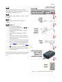
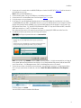
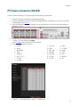
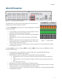
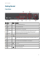
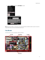
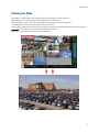
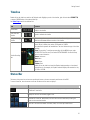
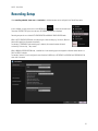
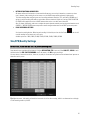
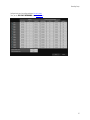
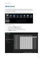
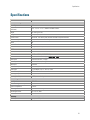
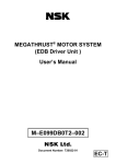
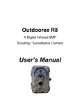
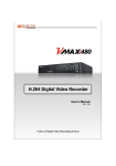
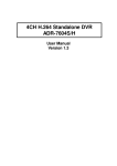
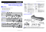
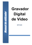
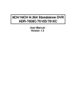
VEO EMBEDDED DVR Rev. 141112 v.1.3 16 Quick Operation Manual ©2014 i3 International Inc. The contents of this user manual are protected under copyrights and computer program laws. Table of Contents Installation ................................................................................................................................................................................ 1 Precautions .......................................................................................................................................................................... 1 Accessories .......................................................................................................................................................................... 2 Rear View ............................................................................................................................................................................ 3 Basic Layout......................................................................................................................................................................... 4 Installation Instructions ......................................................................................................................................................... 4 PC Connection on Local Network ........................................................................................................................................... 6 PC Connection on Remote Network ....................................................................................................................................... 8 PTZ Camera Connection (RS-485) .........................................................................................................................................10 Alarm I/O Connection ...........................................................................................................................................................11 Getting Started ........................................................................................................................................................................12 Front View ..........................................................................................................................................................................12 Log In .................................................................................................................................................................................13 Log Out...............................................................................................................................................................................13 System Shutdown ...............................................................................................................................................................13 Live Screen .........................................................................................................................................................................14 Viewing Live Video ..........................................................................................................................................................15 Timeline ..............................................................................................................................................................................16 Status Bar...........................................................................................................................................................................16 View Event Log ...............................................................................................................................................................17 Quick Menu.........................................................................................................................................................................19 Digital Zoom ...................................................................................................................................................................19 Instant Snapshot Export...................................................................................................................................................20 PTZ Mode................................................................................................................................................................................25 Preset Recall .......................................................................................................................................................................27 Creating New Presets ..........................................................................................................................................................27 Preset Scan ....................................................................................................................................................................28 Preset Tour.....................................................................................................................................................................29 Video Search............................................................................................................................................................................31 Search Window ...................................................................................................................................................................31 Playback Window ................................................................................................................................................................33 Video Export ............................................................................................................................................................................34 Exported Video Playback ......................................................................................................................................................37 i Table of Contents Using Veo16 Backup Player .............................................................................................................................................37 Using Windows Media Player ...........................................................................................................................................41 Recording Setup .......................................................................................................................................................................43 Auto Configuration Mode .....................................................................................................................................................44 Size/FPS/Quality Settings .................................................................................................................................................45 Motion Sensor .........................................................................................................................................................................48 Sensitivity Level ...................................................................................................................................................................49 Motion Detection Area .........................................................................................................................................................49 Web Viewer .............................................................................................................................................................................51 IP Address Information .........................................................................................................................................................51 Connecting via Web Browser ................................................................................................................................................53 Search Video via Web Viewer ...............................................................................................................................................56 Export Video via Web Viewer................................................................................................................................................58 Setting Destination Folder ................................................................................................................................................58 Exporting AVI video .........................................................................................................................................................59 Exported AVI Video Playback............................................................................................................................................60 Troubleshooting (FAQ) ..............................................................................................................................................................62 Specifications ...........................................................................................................................................................................63 ii Veo16 – User Guide Installation Thank you for purchasing an i3 Veo16 digital video recorder. In order to function properly and to its full potential, i3 Veo16 unit must be located in a clean dust free room and a well ventilated area with consistent temperatures within the acceptable range of 20-25° Celsius. The acceptable temperature range must be maintained for the stability of the DVR. Operating Relative Humidity in the server room should be 20% to 80% (non-condensing). In addition, an uninterrupted power supply (1000 VA) with a constant power of 118 to 120 AC must be used with each DVR. If the installation environment does not meet the conditions above, there is a risk of system malfunction. i3 International will only warranty its products if the installation environment meets the conditions above. Should the environmental conditions be not met, the DVR warranty will be voided. i3 International highly recommends cleaning the DVR filter regularly to facilitate the proper ventilation and normal air flow inside the unit (if available with your unit). The internal temperature of the units with unclean filters is always higher, which often leads to overheating. If the system needs to be modified or repaired, contact a certified i3 International Dealer/Installer. When serviced by unauthorized technician, the system warranty will be voided. Should you have any problems or questions regarding our products, contact your local i3 International Dealer/Installer. Precautions Installation and serving should be performed only by qualified and experienced technicians to conform to all local codes and to maintain your warranty. Read and keep the instructions for future reference. When installing your Veo16 digital video coder be sure to avoid: excessive heat, such as direct sunlight or heating appliances contaminants such as dust and smoke strong magnetic fields sources of powerful electromagnetic radiation such as radios or TV transmitters moisture and humidity areas with mechanical vibrations fluorescent lamps or objects that reflect light unstable light sources as this may cause flickering temperatures below -10° Celsius or 14° Fahrenheit and above 50° Celsius or 122° Fahrenheit. CAUTION: RISK OF EXPLOSION IF BATTERY IS REPLACED BY AN INCORRECT TYPE. DISPOSE OF USED BATTERIES ACCORDING TO THE INSTRUCTIONS. BEFORE INSTALLATION: Installation should be carried out only by qualified personnel and in accordance with any electrical regulations enforced at the time. The DVR must be placed on a stable surface or mounted in an approved cabinet. Adequate ventilation must be provided, take care not to block any of the air vents on the DVR. Adequate protection against lightning strikes and power surges must be installed to prevent damage to the DVR. 1 Installation If cleaning is necessary, shutdown the DVR and disconnect power first. Use a soft dry cloth only. Never use any abrasive cleaners. Do not attempt to service or repair the DVR as opening or removing covers may cause static damage to the inner DVR components. Refer all servicing to qualified service personnel. Accessories If any parts are missing or damaged, contact the dealer you purchased the DVR from. The DVR packing box includes, in addition to this manual (User Manual CD), Figure 1.1. Veo16 Accessories 1. Power Cable x1. Connect one end to 12V DC Power Adapter (#2 in Figure 1.1) and the other end to the UPS (Uninterrupted Power Supply). Plug in the UPS into the power outlet. IMPORTANT: Without the use of UPS, the unit warranty is void. 2. 12V DC Power Adapter x1. Plug in the Power Cable (#1) on one end, connect to the Power adapter cable (#3 in Figure 1.1) to the other end. 3. Power adapter cable x1. Connect one end to the 12V DC Power Adapter (#2 in Figure 1.1), plug the other end into the 12V port on the back of your Veo16 DVR. (#M on Figure 1.2) 4. Hard Drive screws x10. Standard Veo16 DVR comes pre-installed with 1 x 1TB hard drive. If required, one additional hard drive can be installed i3 International Dealer/Installer after purchase. Use the screws to secure the additional drive, if using. 5. Power cable retainer clip. Secure the power adapter cable (#2 in Figure 1.1) with the power cable retainer clip, then fasten retainer clip to the opening (#F on Figure 1.1). Securing the power cord with the retainer clip will help prevent unintended disconnection of the power from the Veo16 DVR. 6. USB Mouse x1. Plug in the USB mouse into one of the USB ports for easy system navigation (#K in Figure 1.1 and #16 in Figure 2.1) 7. Remote Control x1. Veo16 Remote control can be used to operate the DVR as an alternative to USB mouse and the front panel buttons. 8. AAA batteries for the Remote Control x2 Install 2 AAA batteries into your Veo16 DVR remote control before using. 2 Installation Rear View Figure 1.2. Veo16 DVR, rear view. No. Name A B VIDEO IN AUX SPOT OUT C D E AUDIO IN AUDIO OUT WAN (UPLINK) F POWER CABLE SECURE H ALARM IN RELAY RS485 VGA I HD-MONITOR J K eSATA USB NTSC/PAL DIP Switch DC 12V G L M Description BNC camera input. Connect up to 16 analog camera inputs. Connect the Main BNC Monitor. Used for SPOT OUT monitor only. Note: Use HDMI cable to connect the HD class monitor (I). Connect up to 4 Audio Inputs. Connect an Audio Output. Network port used to connect to the Internet, router or hub. Secure the power cable with the power cable retainer clip (#5 in Figure 1.1), then fasten retainer clip to the opening. Securing the power cord with the retainer clip will help prevent unintended disconnection of the power from the Veo16 DVR. Alarm Input signal port. Connect up to 4 alarm inputs. Relay Terminal output port. Connect up to 2 relay outputs. Communication port for PTZ camera. Connect VGA monitor video output. Connect 1080p 60Hz HDMI video monitor. Note: Your monitor must support 1920 x1080 at 60Hz when DVR is set to NTSC standard and 1920 x 1080 at 50Hz/60Hz when DVR is set to PAL standard. Connect external eSATA storage. Connect USB mouse or USB storage. Use to set Video Standard (NTSC/PAL). If the unit is set to NTSC standard, all connected analog cameras must also support/be set to NTSC standard. Connect Power Adapter Cable (included, #3 in Figure 1.3). 3 Installation Basic Layout Figure 1.3. Veo16, Basic Layout. Connecting peripheral devices to your Veo16 DVR. Installation Instructions IMPORTANT: The use of UPS (Uninterrupted Power Supply) is mandatory to maintain DVR warranty. Before installation: Ground Yourself. This will remove any static electrical charge your body might be carrying. Connect the peripheral devices by following the instructions below. Step 1. Plug in the USB mouse into the USB port in the front or the back of the unit. Step 2. Plug in your monitor. Depending on the monitor model, use either HDMI or a VGA port on the back of the unit. To connect a DVI monitor, use HDMI-DVI adapter (not included). Note: For proper display, your monitor must support 1920 x1080 at 60Hz. Step 3. Connect analogue cameras to the VIDEO IN BNC video ports #1-16. Step 4. Connect RS485 communication cable for PTZ cameras to the corresponding ports on the back of the DVR, if using. 4 Installation Step 5. Connect other peripheral devices, such as Spot Out and/or Auxiliary BNC monitors, BNC Audio Inputs/Output, Alarm Inputs, Relay Outputs, or eSATA storage, if using. Step 6. Connect the Internet cable to WAN port on the back of the DVR, if applicable. Step 7. Set the NTSC/PAL dip switch to your video standard, if applicable. Step 8 (see Fig. 1.4). Connect Veo16 DVR to the Power Source. a. Connect the Power Adapter Cable to the DC 12V port on the back of the Veo16 DVR. b. Connect the 12V DC Power Adapter to the Power Adapter Cable. c. Connect the Power Cable to the DC 12V Power Adapter. d. Connect the Power Cable to the UPS (Uninterrupted Power Supply). The use of the UPS is mandatory to maintain DVR warranty. e. Connect the UPS to the Power Source / power outlet. f. Secure the power cable with the power cable retainer clip (#5 in Figure 1.1), then fasten retainer clip to the opening on the back of the Veo16 DVR (#F in Figure 1.2). Securing the power cord with the retainer clip will help prevent unintended disconnection of the power from the Veo16 DVR. Once Veo16 DVR is connected to the power source, it will power on. If it does not, press the Power button on the DVR's front panel. Figure 1.4. Connecting Veo16 DVR to the Power Source 5 Installation PC Connection on Local Network Veo16 DVR can be accessed from desktop PC on a Local Area Network (LAN). This allows viewing live or recorded DVR video, exporting saved video clips and adjusting settings from multiple local PC stations. Figure 1.5. Local PC connection to the Veo16 DVR on LAN, topography diagram Figure 1.6. Local PC connection to the Veo16 DVR on LAN, connection diagram 6 Installation To access Veo16 DVR remotely via Web Browser on a local network, follow instructions below: 1. 2. 3. 4. 5. 6. Connect one end of a network cable to the WAN (UPLINK) port on the back of the DVR (#E in Figure 1.2) and the other end to the broadband router or a hub. Note: Do NOT use LAN (DOWNLINK) port. Connect the local PC to the broadband router or hub. Use diagram Figure 1.6 above as a guide. Open the web Browser window on the connected local PC. Enter the Veo16 IP address into the address bar of your Web Browser in this format: "http://IP Address:8080). The DVR Web Service Port is set to Port 8080 by default but can be changed in the DVR's Network Setup screen. Refer to Network Setup section of this manual. E.g. http://192.0.0.150:8080 In the Windows Security login window, enter Veo16 Login and Password. Important: Veo16 login and password information is case-sensitive. Note: Factory Default Login: ADMIN, Password: 1234. For Security purposes, it is highly recommended that you change the factory default administrative password after the initial login. You can change administrative password, add and remove DVR users in System Setup -> User Management screen. Refer to User Management section of this manual. The first time you connect to the Veo16 over the local network, your web browser may ask you to install a required Add-on. Click on the pop-up menu below the address bar, and select "Install This Add-on for All Users on This Computer..." option. In the next window, click Install. Your Veo16 DVR can now be controlled via Web Browser. 7 Installation PC Connection on Remote Network Veo16 DVR can be accessed from desktop PC on a Wide Area Network (WAN). This allows viewing live or recorded DVR video, exporting saved video clips and adjusting settings from multiple remote PC stations. Figure 1.7. Remote PC connection to the Veo16 DVR on WAN, topography diagram Figure 1.8. Remote PC connection to the Veo16 DVR on WAN, connection diagram 8 Installation 1. 2. 3. 4. 5. 6. 7. Connect one end of a network cable to the WAN (UPLINK) port on the back of the DVR (#E in Figure 1.2) and the other end to the broadband router or a hub. Note: Do NOT use LAN (DOWNLINK) port. Connect the ADSL modem, if using, to the WAN port on the broadband router or hub. Connect the local PC to the broadband router or hub. Use diagram Figure 1.7 as a guide. If using the router, set the port forwarding. On the remote PC, open the Web Browser window and enter the Veo16 DDNS address into the address bar in this format: "http//DVRNAME.dvrlink.net:8080". The DVR Web Service Port is set to Port 8080 by default but can be changed in the DVR's Network Setup Screen.By default, DVRNAME is set to the Veo16 MAC Address but can be changed to a custom value in the DVR's Network Setup Screen.. E.g. "http://00115f123456.dvrlink.net:8080" OR "http://veo16.dvrlink.net:8080", where DVR NAME value has been set to "veo16" in the Network Setup screen. Refer to Network Setup section of this manual for more information on changing DVR's DDNS name and/or Server Port. In the Windows Security login window, enter Veo16 Login and Password. Important: Veo16 login and password information is case-sensitive. Note: Factory Default Login: ADMIN, Password: 1234. For Security purposes, it is highly recommended that you change the factory default administrative password after the initial login. You can change administrative password, add and remove DVR users in System Setup -> User Management screen. Refer to User Management section of this manual. The first time you connect to the Veo16 over the local network, your web browser may ask you to install a required Add-on. Click on the pop-up menu below the address bar, and select "Install This Add-on for All Users on This Computer..." option. In the next window, click Install. Your Veo16 DVR can now be controlled via Web Browser. 9 Installation PTZ Camera Connection (RS-485) In order to connect and operate your PTZ camera through Veo16 DVR, follow instructions below: 1. 2. 3. 4. 5. Ensure your PTZ camera is connected to the appropriate power supply. Connect the RS485 wires from the PTZ camera to the corresponding RS485+ and RS485- ports on the back of Veo16 DVR, see diagram below. (#G in Figure 1.2) Plug in the BNC video cable from the PTZ camera into one of the VIDEO IN ports on the back of Veo 16 DVR, see diagram below (#A in Figure 1.2). Configure correct PTZ Camera Address, Protocol and Baud Rate according to the PTZ Camera specifications in System Setup > Camera -> PTZ Setup screen and click Apply. Refer to PTZ Mode section of this manual for more information. Veo16 supports the following PTZ Protocols: 1. PELCO-D 9. Spd_3300 16. TAKEX 2. PELCO-P 10. Multix 17. LPT-A100L 3. MESA-DOME 11. MRX_1000 18. interM 4. D-Max 12. WV-cs850 19. VITEK 5. FastraxII_2 13. WV-crs604 20. LILIN 6. Ganz_PT_V3_2 14. PTC-400c 21. MAXPRO 7. SCC_641 15. PTC-200 22. VCL 8. SCC_643a Figure 1.9. Veo16 System Setup -> Camera -> PTZ Setup screen 10 Installation Alarm I/O Connection Figure 1.10. Veo16 rear, Alarm In/Out terminals Veo16 DVR supports up to 4 Alarm In (Sensor) sensor devices, (such as motion sensor, for example) and up to two Alarm Out/Relay control devices. To connect an alarm input device such as sensor to the rear [ALARM IN] port of Veo16 DVR, follow instructions below: 1. 2. 3. 4. 5. Use a pointed object, such as a screw driver to push the top orange portion of the desired Alarm IN (IN1, IN2, IN3, IN4) and GND terminals in. While pushing, insert one end of the alarm signal cable into the desired ALARM IN terminal opening. While pushing, insert one end of the alarm ground cable into the GND terminal opening. Release the orange portion of the terminal and gently pull on the cables to ensure Figure 1.11. Veo16 rear, Alarm proper and secure connection. If the cable dislodges, repeat steps 1-3, this time In/Out terminals, detail inserting the cable further inside the terminal. To remove the alarm input cable, use a pointed object to push the top orange portion of the corresponding terminal inwards, while pulling gently on the cable. To connect a relay device such as a normally-open (NO) or normally-closed (NC) control device to the rear [ALARM IN] port of Veo16 DVR, follow instructions below: 1. 2. 3. 4. 5. Use a pointed object, such as a screw driver to push the top orange portion of the desired RELAY (NO1, NC2) and corresponding ground COM (COM1, COM2) terminals in. While pushing, insert one end of the signal cable into the desired RELAY terminal opening (NO1/NC1) NO (Normally Open) - relay is in Open position by default, but switches to Closed position when an alarm event occurs. NC (Normally Closed) - relay is in Closed position by default, but switches to Open position when an alarm event occurs. COM - relay ground wire terminal. While pushing, insert one end of the signal cable into the COM terminal opening. Release the orange portion of the terminal and gently pull on the cables to ensure proper and secure connection. If the cable dislodges, repeat steps 1-3, this time inserting the cable further inside the terminal. To remove the relay output cable, use a pointed object to push the top orange portion of the corresponding terminal inwards, while pulling gently on the cable. 11 Veo16 – User Guide Getting Started Front View Figure 2.1. Veo16, Front Panel No. Name 1 2 3 4 5 Button Description 7 Turn Veo16 Embedded DVR ON or OFF Click to switch between various available display modes in Live and Playback modes. Open the Search Mode window In Live Mode, open the Setup menu In Live Mode, open the PTZ Control window Press to display the corresponding video channel in Live and Playback modes. Channel Selection Use I+ button to enter camera double-digit video channel numbers (10 and up). The Buttons numbered buttons are also used to enter numeric passwords in the login screens. ▲▼◄► Use cursor keys to navigate various system menus. Cursor Keys 8 ENTER 9 RETURN 6 POWER DISPLAY SEARCH MENU PTZ/FOCUS Apply or select an item in the menu. Cancel an operation or return to the previous menu / screen. 10 Shuttle Wheel 11 12 13 14 15 16 JOG HOLD Fast Rewind Pause/Resume Fast Forward USB Ports x2 CD/DVD Eject 17 Button ◄◄ ▌▌ ►► Quickly adjust playback direction and speed. Also used to control camera Zoom when in PTZ mode. Use in Playback mode to move footage forward / backward, frame-by-frame Lock the current function of the Shuttle Wheel so it can be released. Increase reverse playback speed Pause / resume Increase video playback speed Connect USB mouse or USB storage Press to eject the CD-ROM tray 12 Getting Started Log In 1. 2. 3. Upon start up, the login screen will be displayed Select the user ID from the drop-down menu and enter the password in the corresponding field. The default user ID is "ADMIN", the default password is "1234". Click OK For security purposes, it is recommended to change the administrator password after the first login. Log Out To prevent unauthorized access, it is recommended to log out of the DVR when not in use. 1. 2. Hover the mouse cursor near the bottom of the Live screen to display the Status Bar. Click on the MENU button and select LOG OUT from the list. System Shutdown To shut down Veo16 DVR, follow instructions below: 1. Position your mouse cursor in the bottom left-hand corner of the screen to bring up the Status Bar. 13 Getting Started 2. Click on the MENU button and select SHUTDOWN from the list. 3. Use the virtual keyboard to enter the password. 4. Click OK to shut down Veo16 DVR. Note: Shutting down the DVR in an unsafe manner, such as removing the power cord while the system is in operation, may result in corrupt hard drive sectors, data loss and shortened hard drive life cycle. Live Screen Live Screen consists of Live View, Quick Menu, Timeline and Status Bar. 14 Getting Started Viewing Live Video After logging in, you will be able to view live video from all connected cameras in a multi-screen view. Where camera is out of order, black screen will be displayed with text “VIDEO LOSS”. Call your installer for service if a previously working camera can no longer be seen in the Live view screen. In the example below, video loss has been detected on Channels 15 and 16. To bring a specific camera screen into full screen mode, position your mouse cursor over the camera video stream on the screen and double-click the left mouse button. The camera will be maximized on the screen. Double-click on the screen again to return to the multi-screen display. 15 Getting Started Timeline Double-click on the timeline to switch to the Playback mode. Highlight a portion of the timeline, right-click and select EXPORT TO, to create a CD/DVD backup of the selected video clip. See Video Export section for additional info. Item Function Timeline Date Displays the date of the current timeline. Click to select a different recording date to display in the timeline. Zoom in/out the Timeline Expand or minimize the timeline. Navigation through Timeline Move to the previous or next section of the timeline. Alternatively, use the mouse wheel to scroll between different sections of the timeline. The orange text represents the month and date: MM-DD. Gray text represents the time of the day in military time, where 15:00 stands for 3:00PM. The colored bars represent the recorded data. The color indicates the type of the video recording: - Lime: Pre-recording. To configure pre-recording, click the MENU button, select RECORD SETUP from the menu, then select OPERATION MODE. See Record Setup section for more information. - Green: Continuous - Red: Alarm - Blue: Motion - Yellow: Panic Double-click on the timeline to launch the Playback mode queued up to the selected time and date. In this example, the Playback mode will display video recorded on July 10, 2014 at 3:00PM. Timeline Recording Bars Status Bar The buttons in the status bar on the screen provide quick access to the most commonly used features of the DVR. To access Status Bar, hover the mouse cursor near the bottom of the screen to display it. Status Bar Icon Function Displays the main menu window. Select "Search, Archiving, System Setup, Record Setup, Log Out or Shutdown" from the list. Displays the User ID of the currently logged in user. Show/Hide the Status Bar. When hidden, the Status Bar can still be accessed by hovering the mouse over the status bar/timeline. Select one of the four screen modes: Full screen, Quad, 3x3 or 4x4 split screen division. 16 Getting Started Status Bar Icon Function Activate Auto Sequence mode. Sequencing can be configured under MENU -> SYSTEM SETUP -> DISPLAY -> SEQUENCE menu. Display or hide the OSD menus on the screen. Switch to the PTZ screen mode, where you can control your connected and configured PTZ cameras, create Presets and configure PTZ Scan/Tours. Refer to PTZ Mode section of this manual for more information. Switch to the Digital Zoom screen mode, where you can digitally zoom into live video image on the selected video channel. Displays the event log of the recent recording events. Double-click a desired log entry to display the video linked to the event in the Playback screen. Activate this icon to listen to the audio from the selected video channel. Audio output (e.g. speaker) must be connected to the unit. Initiate emergency/panic recording. / Icon blinks after pre-configured event occurs. Click on the icon to view details of the event. Event categories include motion sensor, video loss, system event, tamper event. To configure an event, open MENU -> SYSTEM SETUP -> EVENT setup. Displays network connection status and information, such as IP Address, MAC Address, DDNS Address, RTSP Service port, Web Service Port, and External IP Address, as well as the list of remote clients currently logged into the unit via remote PC. This information is for display purposes only. To learn how to make changes to network settings, please refer to Network Setup section of this manual. Displays the disk space information. "OW" is displayed when the DVR switches to Overwrite mode (if configured). Displays current date/time. View Event Log To view the list of the events that have occurred in the past hour, click the Event Log button in the Status Bar. Status Bar, hover the mouse cursor near the bottom of the screen to display it. Event Log window will be displayed with a list of recent events. The list consists of the event logs generated in the past hour and is constantly being overwritten by newer events. To view the video linked to the log event, double-click a desired log record in the list. To access the 17 Getting Started Playback window will be displayed with the linked channel in full-screen mode and the video queued up to the event log time. In this example, the selected log is related to CAM1 and took place on July 9, 2014 at 2:08:53PM. Use the playback control panel in the Playback Window to view the video. To exit the Playback screen and return to the Live screen mode, click MENU and select LIVE from the list. 18 Getting Started Quick Menu Right-click on a channel to display a quick menu popup window. Menu Item Function Channel No (CAMX) Displays the camera number of the current channel. Start the playback of the selected channel. Select from 10 sec, 20 sec, 30 sec or 1 min ago. Select SPECIFIC to play back the video from a particular date and time. A separate window will pop up, where you may enter the year, month, day, hour, min and seconds for the video start time. After the selection is made, the selected video channel will be displayed in a Full Screen mode in the Playback screen. Playback Switch to the Digital Zoom screen mode, where you can digitally zoom into live video image on the selected video channel. Save the current live video as a *.JPEG file. To save to your external storage, connect an external USB memory device and click the EXPORT button in the SNAPSHOT window. See Saving a Snapshot section for additional info. Digital Zoom Snapshot Digital Zoom Digital Zoom option allows enlarging a portion of the live video screen for closer inspection. Important: Digital zoom function magnifies existing video stream, which may make the resulting image appear grainy, pixelated or of poor quality. For best qualify video magnification, use the built-in optical zoom capability of your camera, wherever available. To use the Digital Zoom option, follow instructions below: 1. Digital Zoom mode can be accessed in one of two ways: Right-click on the desired channel in Live screen and click ZOOM in the quick menu window. Use your mouse cursor to select the desired channel in Live screen. Next, hover the mouse cursor near the bottom of the screen to display the Status bar and click the Zoom button. 19 Getting Started 2. Digital Zoom window will be displayed. 3. Use the Digital Zoom Panel in the bottom right-hand corner to zoom in and out of live video. Use the drop-down menu to select a live channel for digital zooming. Zoom into the current image, up to 6 times. Zoom out of the current image. 4. Exit Digital Zoom mode and return to the Live screen. Notice the navigator window in the bottom right-hand corner just above the Digital Zoom panel, which displays the thumbnail of the current video channel screen. The yellow outline inside the navigator window is called the View box and shows the amount of image visible on the screen at the current zoom level. Use your mouse cursor to move the View box anywhere in the Navigator Window. The main screen display will change to match the view inside the yellow outline. Instant Snapshot Export Quick Menu offers a way to save a *.jpg snapshot to a removable USB storage drive. Follow instructions below: 1. 2. 3. Connect USB storage to one of Veo16 USB ports. (#16 in Figure 2.1 and #K in Figure 1.2). Right-click on a channel to display a quick menu popup window. Click SNAPSHOT in the quick menu window. 20 Getting Started 4. In the SNAPSHOT window, click EXPORT to save the *.jpg image to your connected USB media. 5. 6. In the EXPORT window, select the USB media in the DEVICE NAME drop-down menu. Double-click on the TAG NAME field and use the virtual keyboard to enter any custom information to be stored with the file. Tag name info will be saved in an arch_info.txt log file which accompanies the saved *.jpg snapshot file. 7. Double-click on the MEMO field and use the virtual keyboard to enter any additional information (optional). Memo info will be saved in an arch_info.txt log file which accompanies the saved *.jpg snapshot file. Click BURN to save the *.jpg snapshot to the selected media. Click OK in the confirmation window. Your snapshot has now been saved. 8. 9. Reserving Snapshot in the absence of USB Media If a snapshot must be saved but USB media is unavailable, the Snapshot can be temporarily saved (reserved) on the Veo16 hard drive. Follow instructions below for first reserving, and later burning the reserved Snapshot to the USB media. 1. Right-click on a channel to display a quick menu popup window. 21 Getting Started 2. Click SNAPSHOT in the quick menu window. 3. In the SNAPSHOT window, click RESERVE to save the *.jpg image to your Veo16 hard drive. Confirmation window will be displayed briefly. 4. 5. Click CLOSE to close the SNAPSHOT window. Once you are ready to move the reserved snapshot(s) from the Veo16 hard drive to a portable USB media, hover the mouse cursor near the bottom of the screen to display the status bar. Click on the MENU button and select ARCHIVING from the list. 6. 7. In the ARCHIVING window: Step 1. Click on the RESERVED DATA MANAGEMENT tab. Step 2. Select SNAPSHOT from the drop-down window in the bottom left-hand corner. Step 3. Select the desired snapshot from the list. 22 Getting Started Step 4. Click the EXPORT button 8. In the SNAPSHOT window, click EXPORT. 9. In the EXPORT window, select the USB media in the DEVICE NAME drop-down menu. 23 Getting Started 10. Double-click on the TAG NAME field and use the virtual keyboard to enter any custom information to be stored with the file. Tag name info will be saved in an arch_info.txt log file which accompanies the saved *.jpg snapshot file. 11. Double-click on the MEMO field and use the virtual keyboard to enter any additional information (optional). Memo info will be saved in an arch_info.txt log file which accompanies the saved *.jpg snapshot file. 12. Click BURN to save the *.jpg snapshot to the selected media. 13. Click OK in the confirmation window. Your snapshot has now been saved. 24 Veo16 – User Guide PTZ Mode PTZ mode allows the user control their PTZ cameras, create new presets and re-position the camera to previously-saved To control your connected and configured PTZ cameras, hover the mouse cursor near the bottom of the Live screen to display the Status Bar. Click the PTZ mode button on the Status Bar . PTZ Mode screen will be displayed. Consult the diagram below to see the general purpose of each area of the PTZ Mode screen. To display another PTZ channel without exiting PTZ mode, select the desired channel from the Channel Selection drop-down menu or click on the Channel number in the Recording Status area in the bottom right-hand corner of the screen. Figure 2.1. PTZ Mode Screen, diagram 25 PTZ Mode Controlling your PTZ Camera Use the Pan/Til Control Panel to change your Use the Zoom/Focus/Iris panel to Zoom In/Out, to Focus In/Out or to adjust the image PTZ camera position. brightness by opening or closing the lens iris. Note, this function controls the lens' built- in zoom capabilities, and is not the same as Digital Zoom function available in the Live screen. To view or adjust PTZ properties, click the PROPERTY button in the Pan/Tilt Control Panel. PTZ PROPERTY window will be displayed. PTZ Driver configured for the current selected PTZ channel is shown but cannot be adjusted from this menu window. To change the PTZ Protocol, go to System Setup -> Camera -> PTZ Setup screen. The following changes can be made to the PTZ settings of the selected channel. Use the up/down arrows to change the values. Set the AUTO FOCUS to ON or OFF Set the AUTO IRIS to ON of OFF Set the P/T SPEED value from 1 to 10, where 1 is slow and 10 is fast. Default value = 5. Set the ZOOM SPEED value from 1 to 10, where 1 is slow and 10 is fast. Default value = 5. Set the FOCUS SPEED value from 1 to 10, where 1 is slow and 10 is fast. Default value = 5. Set the IRIS SPEED value from 1 to 10, where 1 is slow and 10 is fast. Default value = 5. Click OK to save the settings or CANCEL to discard any changes. TROUBLESHOOTING Q: Why can't I control my PTZ camera? A: Please make sure your camera is correctly installed and configured in the Veo16 Setup tab. Check the wiring first, then check all camera settings, including Camera Address, Protocol and Baud Rate, then try again. 26 PTZ Mode Preset Recall Veo16 DVR supports up to 255 unique presets. To recall an existing preset, use the arrows in the NO. field to select a desired preset then click the GoTo icon next to the NAME field. The camera will move to the preset position. Alternatively, click the GoTo icon next to the corresponding preset in the Quick Access list. Creating New Presets Veo16 DVR supports up to 255 unique presets. To create a new preset, 1. Use the up/down arrows to select the Preset number or double-click inside the NO. field and use the virtual keyboard to enter the preset number between 1 and 255. 2. Double-click inside the NAME field and use the virtual keyboard to enter the preset name. 3. Click the SET button. 4. First 16 presets are saved to the Quick Access list. Once the list fills up, no new presets can be saved to the Quick Access list. To free up space in the Quick Access list for a new preset, delete one of the existing presets from the list by clicking a corresponding Remove icon have to be re-configured. . Note that this action will permanently remove the preset from the database and it will 27 PTZ Mode Preset Scan Preset Scanning allows the camera to pan continuously between two selected presets. The pan speed is slower for Preset Scan than it is for Preset Tour. With Preset Scan, PTZ camera pans slowly, allowing you to view the entire scene between the two configured presets. Note: Preset Scanning and Preset Touring are mutually exclusive features. Only one may be used at-a-time. To set the PTZ camera for preset scanning, follow instructions below: 1. 2. In PTZ mode, create at least two presets. In the bottom left-hand corner, in the SCAN/TOUR drop-down menu select SCAN. 3. Next, click the ON button to activate preset scanning. 4. Click on the Properties icon 5. In PTZ SCAN window, select two presets, one for each step of the preset scanning. Use the drop-down PRESET menu to make your selections. In the DWELL drop-down menu, set the DWELL time for each preset. Dwell time will determine how long the camera will display the preset for before panning to the second preset. Dwell time can be set between 1 and 20 seconds. Default value: 5 seconds. In this example, the camera will display Preset#2 "Parking A" for 5 seconds, then pan to Preset#3 "Front door" and stay there for 10 seconds before returning to Preset "Parking A", and so on. 6. 28 PTZ Mode 7. Click OK to save changes. Preset Tour Preset Touring allows the camera to pan continuously between up to 16 selected presets. The pan speed is faster for Preset Tour than it is for Preset Scan. With Preset Tour, PTZ camera pans quickly from preset to preset, showing only the preset locations but not the scene in-between. Note: Preset Scanning and Preset Touring are mutually exclusive features. Only one may be used at-a-time. To set the PTZ camera for preset touring, follow instructions below: 1. 2. In PTZ mode, create at least two presets. In the bottom left-hand corner, in the SCAN/TOUR drop-down menu select TOUR. 3. Next, click the ON button to activate preset scanning. 4. Click on the Properties icon 29 PTZ Mode 5. In PTZ TOUR window, select up to 16 presets, one for each step of the preset touring. Use the drop-down PRESET menu to make your selections. 6. In the DWELL drop-down menu, set the DWELL time for each preset. Dwell time will determine how long the camera will display the preset for before panning to the next preset. Dwell time can be set between 1 and 20 seconds. Default value: 5 seconds. In this example, the camera will display Preset#2 "Parking A" for 5 seconds, then pan to Preset#3 "Front door" and stay there for 10 seconds, then pan to Preset #20 "PRESET-20" and say there for 12 seconds, and so on. Click OK to save changes. 7. 30 Veo16 – User Guide Video Search To search recorded video, move your mouse cursor to the lower left-hand corner. On-screen menu will be displayed. Click the MENU button , then select and click SEARCH item from the pop-up menu list. The SEARCH window will be displayed. Search Window Your DVR uses a calendar and timeline search method for quick access to recorded footage. The recorded footage is represented by colored bars. - Lime: Pre-recording. To configure pre-recording, click the MENU button, select RECORD SETUP from the menu, then select OPERATION MODE. See Record Setup section for more information. - Green: Continuous - Red: Alarm - Blue: Motion - Yellow: Panic The lower portion of the screen offers at-a-glance preview of the video. The vertical blue line indicates the playback start time in the timeline. Use the mouse cursor to position it on the timeline. Select the video channel thumbnail, the video will start playing in the PREVIEW window (bottom left-hand corner) starting from the selected timeline point. 31 Video Search Follow three steps below to search video recording. Step 1. Using your mouse cursor click on the calendar day you would like to search. Use the left/right arrows to select previous/next calendar month. Note: Only days highlighted in yellow have recorded video footage. As different days are selected, the timeline display also changes to show recorded footage on that day. Step 2. Using your mouse cursor click on the clock icon below the calendar. The DATE/TIME window will be displayed. Using the up/down arrows, set the playback start time (year, month, day, hour, minute, second). When done, click OK to confirm the playback start time. Step 3. Click the PLAYBACK button in the bottom right corner. The PLAYBACK window will be displayed. Note: To exit SEARCH mode and return to LIVE mode, click the CLOSE button in the SEARCH screen. 32 Video Search Playback Window Playback window is used to review video footage recorded to the internal hard drive. Use your mouse cursor to double-click on the camera view you would like to see in the Full Screen mode. To bring a specific camera screen into full screen mode, position your mouse cursor over the camera video stream on the screen and doubleclick the left mouse button. The camera will be maximized on the screen. Double-click on the screen again to return to the multi-screen display. Use the Playback Control panel at the bottom of the screen to control video playback. 33 Veo16 – User Guide Video Export Video clips can be exported from the ARCHIVING mode. Start by plugging in your USB flash drive into the USB port on the front panel of the DVR, if using, OR Press the CD/DVD eject button on the front panel of the DVR and insert a blank CD or DVD disk into the drive. Press the eject button again to close the drive. In the Live Mode or Playback Mode, use your mouse cursor to click MENU button select ARCHIVING option from the menu. ARCHIVING window will be displayed. in the bottom left-hand corner. Then Your DVR uses a calendar and timeline search method for quick access to recorded footage. The recorded footage is represented by colored bars. The lower portion of the screen offers at-a-glance preview of the video. 34 Video Export To export a video clip to a CD/DVD or a USB media, follow these steps: Step 1. Using your mouse cursor click on the calendar day you would like to search. Use the left/right arrows to select previous/next calendar month. Note: Only days highlighted in yellow have recorded video footage. As different days are selected, the timeline display also changes to show recorded footage on that day. Step 2. Select the cameras for backup. To select all video cameras for backup, use your mouse cursor to check the ALL checkbox. To save one or more cameras, check the corresponding camera checkboxes. In this example, all cameras have been selected for backup. Step 3. Using your mouse cursor click on the clock icon below the calendar in the FROM line . The DATE/TIME window will be displayed. Using the up/down arrows, set the playback start time (year, month, day, hour, minute, second). When done, click OK to confirm. This will set the start time for the backup video clip. Repeat for the TO line to set the end time for the backup video clip. In this example, the FROM time has been set to 2:21:21PM and the TO time is set to 2:26:21PM, for a total video clip length of 5 minutes Step 4. Click the QUERY button to calculate the total size of the video backup. Make sure there is sufficient available empty space on your USB device or CD/DVD disk to accommodate the file of that size. In this example, the total size of the backup is 835.6 MB. Step 5. Click the EXPORT button. EXPORT window will be displayed. 35 Video Export Step 6. In the DEVICE NAME drop-down menu, select the backup destination. Step 7. In the DATA FORMAT drop-down menu, make sure that AVI format is selected Step 8. Double-click on the TAG NAME field. Using the on-screen VIRTUAL KEYBOARD, enter the backup tag name. When done, click OK in the VIRTUAL KEYBOARD window to close it. Step 9. Click the BURN icon to begin the backup process. Step 10. Wait while the AVI file is being written to your backup media. Click OK in the NOTICE window to complete the backup process. Your backup is finished. Remove your backup media: USB or CD/DVD. 36 Video Export The backup AVI clips have been saved to your selected media. AVI Player is included with the installation package. Exported Video Playback After your AVI video has been exported to a USB drive or a DVD disk, you can play it back on any Windows PC. You may choose to: A. Play the video clips with Veo16 Backup Player (included with the exported video) OR B. Play the video clips with your Windows Media Player. To do so, you will have to install the IMM4 codec first (included with the exported video). Using Veo16 Backup Player To playback your exported video with Veo16 Backup Player, follow these instructions: 1. 2. Start by plugging in your USB flash drive with the exported video into an available USB port on your PC, OR Insert your CD/DVD with the exported video into your PC’s DVD-ROM. On your media, find the ARCHIVE folder. The name of the backup folder includes the date and time that the video export was completed. In this example, the folder name is “ARCHIVE_140221_150647”, which means that the video was exported on February 21, 2014 at 3:06:47PM. 37 Video Export 3. Inside the ARCHIVE folder, find the PLAYER folder and double-click to open it. 4. Inside the PLAYER folder, find the BackupPlayer.exe file and double-click to run it. Note: You will need administrative rights on your PC to run Veo16 Backup Player. 38 Video Export 5. Backup Player window will be displayed. Click on the Open icon in the bottom left-hand corner of the screen. 6. In the next window, select an exported AVI video file you wish to play and click Open. 7. 8. Click Yes in the Watermark confirmation message. The file will begin playing in the Backup Player window. Use the control panel on the bottom of the screen to control the playback. 39 Video Export 40 Video Export Using Windows Media Player To playback your exported video with Veo16 Backup Player, follow these instructions: 1. 2. 3. 4. Start by plugging in your USB flash drive with the exported video into an available USB port on your PC, OR Insert your CD/DVD with the exported video into your PC’s DVD-ROM. On your media, find the ARCHIVE folder. The name of the backup folder includes the date and time that the video export was completed. In this example, the folder name is “ARCHIVE_140221_150647”, which means that the video was exported on February 21, 2014 at 3:06:47PM. Inside the ARCHIVE folder, find the PLAYER folder and double-click to open it. Inside the PLAYER folder, find the setup.exe file and double-click it to install IMM4 video codec on your PC. Note: You will need administrative rights on your PC to install IMM4 video codec. 41 Video Export 5. IMM4 Codec Setup window will be displayed. Click on Next -> Install -> Finish in the installation windows. 6. Return to the ARCHIVE folder, select an exported AVI video file you wish to play and double-click it. 7. The file will begin playing in the Windows Media Player window. Use the control panel on the bottom of the screen to control the playback. 42 Veo16 – User Guide Recording Setup Video recording schedule, frame rate and resolution for individual cameras can be configured in the Record Setup mode. In the Live Mode, use your mouse cursor to click MENU button in the bottom left-hand corner. Then select RECORD SETUP option from the menu. RECORDING window will be displayed. Recording setup can be set to either AUTO CONFIGURATION or MANUAL CONFIGURATION mode. When in AUTO CONFIGURATION mode, the selected type of video recording (e.g. Continuous, Motion or Alarm) will be applied to all cameras automatically. For example, if CONTINUOUS video recording type is selected, all connected cameras will record continuously, 24 hours a day, 7 days a week. When in MANUAL CONFIGURATION mode, a combination of video recording types can be applied to individual cameras based on a DAILY or WEEKLY schedule. For example, Cameras 1-4 can be configured to record based on ALARM only on SATURDAYS and SUNDAY and CONTINUOUSLY all other times of the week. 43 Recording Setup Auto Configuration Mode Auto Configuration allows selecting just one type of video recording for all connected cameras. Note: To configure video recording based on a schedule, choose MANUAL CONFIGURATION mode. To automatically assign the same video recording type to all cameras, select "AUTO CONFIGURATION" option in MODE drop-down menu. Next, select one of the available video recording types. Only one recording type can be selected in AUTO CONFIGURATION mode. The selected recording type will apply to all connected video channels and will remain active 24 hours a day, 7 days a week. CONTINUOUS RECORD All cameras will record continuously, 24 hours a day, 7 days a week. Select between HIGH QUALITY BUT SHORT DURATION and LONG DURATION BUT LOW QUALITY based on your preferences. Default software settings will be used for these selections, which cannot be adjusted. MOTION RECORD Video recording will occur on the camera only when the motion is detected. Note: For proper functionality, make sure to configure the motion detection sensitivity and set the motion detection area in CAMERA > MOTION SENSOR system setup menu. ALARM RECORD Video recording will occur on LINKED cameras only when an alarm event is detected. Note: For proper functionality, make sure to configure alarm events and link video cameras to those events in the EVENT system setup menu. MOTION / ALARM RECORD Video recording will occur on the camera only when the motion is detected OR when an alarm event is detected. Note: For proper functionality, make sure to configure the motion detection sensitivity and set the motion detection area in CAMERA > MOTION SENSOR system setup menu as well as configure alarm events in the EVENT system setup menu. INTENSIVE MOTION RECORD All cameras will record continuously at a lower resolution/frame rate; once motion is detected on a camera, video recording on that camera will be performed in higher quality. This video recording allows configuring two sets of recording preferences (Resolution, FPS, and Quality). NORMAL set of settings is used for recording video when no motion is detected. Higher set of settings, WHILE IN MOTION, will be applied when motion is detected on a camera. Note: For proper functionality, make sure to configure the motion detection sensitivity and set the motion detection area in CAMERA > MOTION SENSOR system setup menu. INTENSIVE ALARM RECORD All cameras will record continuously at a lower resolution/frame rate; once an alarm event is detected, video recording on LINKED cameras will be performed in higher quality. This video recording allows configuring two sets of recording preferences (Resolution, FPS, and Quality). NORMAL set of settings is used for recording video when no alarm events are detected. Higher set of settings, WHILE IN ALARM, will be applied to LINKED cameras when an alarm event is detected. Note: For proper functionality, make sure to configure alarm events and link video cameras to those events in the EVENT system setup menu. 44 Recording Setup INTENSIVE MOTION/ALARM RECORD All cameras will record continuously at a lower resolution/frame rate; once motion is detected on a camera or an alarm even is detected, video recording on motion camera or on the LINKED camera will be performed in higher quality. This video recording allows configuring two sets of recording preferences (Resolution, FPS, and Quality). NORMAL set of settings is used for recording video when no motion/alarm events are detected. Higher set of settings, WHILE IN MOTOIN OR ALARM, will be applied to motion or LINKED cameras when motion or an alarm event is detected. Note: For proper functionality, make sure to configure the motion detection sensitivity and set the motion detection area in CAMERA > MOTION SENSOR system setup menu as well as configure alarm events in the EVENT system setup menu. PANIC RECORDING OPTIONS Set the panic recording duration. When the panic recording is initiated by user from the Live Screen ( continue recording for the duration set in this option. Available options are: 1 MIN, 5 MIN, 10 MIN, 20 MIN, 30 MIN, 40 MIN, 50 MIN, 60 MIN ), the unit will Size/FPS/Quality Settings For MOTION, ALARM and MOTION / ALARM RECORD options: Once selected, a pop-up window will be displayed. Configure RESOLUTION, FPS (frame rate), Video QUALITY, AUDIO for each individual camera and PRE-/POST-RECORDING time for all cameras, click OK to apply the settings. You may choose to increase the resolution, frame rate, or quality for the cameras facing locations that are deemed most important or where most activity occurs. Tip: Higher frame rate, video quality and resolution increase the size of the video recording, which in turn decreases the total length of video recording stored on your DVR. 45 Recording Setup For each camera: Set the Resolution, FPS, Video Quality, Audio for each individual camera. Click the RESOLUTION drop-down menu and select one the offered recording resolutions. Higher resolution results in 352x240 (CIF) 704x240 (2 CIF) 740x480 (4 CIF/D1) 960x480 (960H) - default Note: The higher the resolution, the more detailed the video image appears and the larger the video recording size. Click the FPS (frames-per-second) drop-down menu and select one of the offered recording frame rates: 1 fps, 2 fps, 3 fps, 7fps (default), 15fps, 30fps (real time) Note: The higher the frame rate, the smoother the video appears and the larger the video recording size. Click the QUALITY drop-down menu and select one of the offered video quality settings: LOWEST, LOW, STANDARD, HIGH, HIGHEST (default) Note: The higher the video quality, the larger the video recording size. Click the AUDIO drop-down menu and set it to either ON or OFF (default). For all cameras: Set the PRE-/POST-RECORDING times for all cameras. Pre-recording time setting specifies the number of seconds appended to the beginning of the video recording. Veo16 DVR will record for the set number of seconds specified prior to an alarm event or motion detection. The DVR keeps a 15-second video buffer that can be added to the beginning of recorded video segment in case of an alarm event or motion detection. Post-recording time setting specifies the number of seconds appended to the end of the video recording after and alarm event or after the motion has stopped. Click the PRE RECORDING TIME drop-down menu and select one of the offered pre-recording times: 0 sec, 1 sec, 2 sec, 3 sec, 4 sec, 5 sec (default), 10 sec, 15 sec. Click the POST RECORDING TIME drop-down menu and select one of the offered pre-recording times: 5 sec, 10 sec, 15 sec, 20 sec, 30 sec, 60 sec, 120 sec, 180 sec. For INTENSIVE MOTION, INTENSIVE ALARM and INTENSIVE MOTION / ALARM RECORD options: Once selected, a pop-up window will be displayed. Configure RESOLUTION, FPS (frame rate), Video QUALITY, AUDIO for each individual camera during NORMAL recording and WHILE IN MOTION and/or ALARM. Then configure PRE-/POST-RECORDING time for all cameras, click OK to apply the settings. These video recording types allows configuring two sets of recording preferences (Resolution, FPS, and Quality). NORMAL set of settings is used for continuous recording when no motion is detected. Higher set of settings, WHILE IN MOTION / ALARM, will be applied when motion is detected on a camera and/or alarm event is detected. 46 Recording Setup Configure both sets of recording preferences for each camera. Then, set the PRE-/POST-RECORDING times for all cameras. 47 Veo16 – User Guide Motion Sensor For proper Motion Recording, Motion Sensor area and settings must be configured in the Veo16 setup. To access Veo16 Setup, hover the mouse cursor near the bottom of the Live screen to display the Status Bar. Select SYSTEM SETUP from the MENU. In the Setup panel, click on the CAMERA item and select MOTION SENSOR from the drop-down list. In MOTION SENSOR setup window, 1. 2. 3. 4. 5. Turn Motion detection ON for each desired camera Turn Motion detection icon ON or OFF (optional) Configure motion detection area for each desired camera Configure Daytime and Nighttime Sensitivity Levels for each camera Click APPLY to save all settings. 48 Motion Sensor Sensitivity Level Sensitivity Level determines the camera's responsiveness to the detected motion. The lower the sensitivity, the more pronounced the motion must appear on screen to be detected. The higher the sensitivity ensures that the smaller changes on the screen get recognized as motion. Separate Sensitivity Levels can be set for Daytime and Nighttime. To configure Sensitivity Levels, double-click on the Sensitivity Level field for the desired camera. In the SENSITIVITY window, 1. 2. 3. 4. Make sure that the correct camera number is selected in the CHANNEL drop-down menu Define the time frame for daytime hours Set DAYTIME and NIGHTTIME sensitivity levels by clicking the up/down arrows. The acceptable Sensitivity Level range is between 1 and 30, where 1 is lowest sensitivity and 30 is the highest sensitivity. By default, both DAYTIME and NIGHTTIME sensitivity levels are set to 15. Click OK to save changes. Motion Detection Area By default, the entire screen area is enabled for Motion detection. To reduce the number of false alarms, the users may choose to select only areas of particular interest. To edit motion detection area, click on the EDIT AREA button the desired camera. 49 Motion Sensor In the Camera preview window, use your mouse cursor to select the area on the screen to be used for Motion Detection. Only the areas on the screen covered by red squares are currently selected. Draw the area on the screen using your mouse cursor. When the desired area has been successfully highlighted, right-click and select SAVE & EXIT option from the context menu. 50 Veo16 – User Guide Web Viewer Veo16 Web Viewer application allows controlling Veo16 DVR from a remote PC via the network connection. Your remote PC must meet the minimum hardware requirements in order to connect to and control Veo16 DVR remotely. Minimum Hardware Requirements: OS: Web Browsers: CPU: Memory: Display: Hard Disk Drive: Windows XP Professional, Windows Vista Home Basic / Premium, Windows 7 IE 7.0 or later (Full support; IE v11 and up must be run in Compatibility Mode to be able to access Search), Mozilla Firefox 3.6 and above (Remote Search not supported), Google Chrome 4.1 and above (Remote Search not supported) Intel Pentium 4 / 2.0GHz or higher 512MB 16-bit 1024x768 High Color 50MB (space requirement for Web Viewer installation). Note: Additional HDD space required for video data backup. Backup video file size differs based on the set frame rate and quality. IP Address Information It is possible to connect to the Veo16 via local or remote network. When connecting through the local network (LAN), use DVR's local IP Address. When connecting through the Internet (WAN), use Veo16's External IP Address. IP Address information must be used in combination with Web Service Port. Also see PC Connection on Local Network and PC Connection on Remote Network sections for more information. To locate Veo16 IP Address and Web Service Port Information, follow instructions below: 1. In the Live Mode, use your mouse cursor to click MENU button SYSTEM SETUP option from the menu. in the bottom left-hand corner. Then select 51 Web Remote View 2. In the Setup panel, click on the NETWORK item and select NETWORK STATUS from the drop-down list. 3. In the Network Status window, locate Veo16's (local) IP address), External IP Address and Web Service Port information. In this example, the local IP address for Veo16 is 192.168.11.45. External IP Address is 209.82.34.92. Web Service Port is 8080. 52 Web Remote View Connecting via Web Browser To connect to Veo16 remotely, start by launching your Web Browser. Important: Only Internet Explorer browser supports remote video export (backup). Search options are not supported by browsers other than Internet Explorer, such as Firefox, Chrome, etc. 1. Launch Internet Explorer browser. Enter Veo16 local IP Address if connecting through LAN or External IP Address, if connecting through WAN, followed by Web Service Port, separated by colon. Follow this standard: http://<IP ADDRESS or EXTERNAL IP ADDRESS>:<WEB SERVICE PORT> 2. Login window will be displayed. Enter your Veo16's User Name and Password. Note that the 3. Veo16's Web Viewer window will be displayed. Four tabs are supposed to appear at the top of the window: LIVE, SEARCH, SETUP, INFORMATION. If all four tabs are displayed, skip instructions below and go to the step 5. 4. If SEARCH tab does not show up in the Web Viewer window, Veo16's IP Address information must first be added to Internet Explorer Compatibility View list. To add Veo16 to Internet Explorer's Compatibility View, click the Tools menu and select Compatibility View settings 53 Web Remote View option from the drop-down menu. 5. In the Compatibility View Settings window, click the Add button. IP address of Veo16 will be added to the list of websites to be displayed in the Compatibility View. Click Close to return to Veo16's Web Viewer main window. SEARCH tab will now be displayed in the Web Viewer window. 54 Web Remote View 6. Next, install WebViewer Control ActiveX add-on when prompted. Click the Install button, as shown in the image below. 7. Once the ActiveX controller is successfully installed, you will be able to view Veo16 live and recorded video remotely. 55 Web Remote View Search Video via Web Viewer Web Viewer allows searching recorded video and saving a video clip to your local storage media from a remote Veo16 DVR. Start by connecting to the remove Veo16 through the Web Browser (IE preferred). Then, click on the SEARCH tab. In the SEARCH tab, recorded video can be searched by TIME/DATE or by an EVENT (e.g. Alarm, Motion, Video Loss, etc.). SEARCH BY TIME tab is selected by default. The recorded footage for each camera is represented by colored bars. The vertical blue line indicates the playback start time in the timeline. Use the mouse cursor to position it on the timeline. - Lime: Pre-recording. To configure pre-recording, click the MENU button, select RECORD SETUP from the menu, then select OPERATION MODE. See Record Setup section for more information. - Green: Continuous - Red: Alarm - Blue: Motion - Yellow: Panic 56 Web Remote View To play back the recorded video, follow these steps: 1. Set the search Year, Month and Date in the drop-down selection menu. In this case, the search date is set to October 29, 2. 2014. Set the search Hour, Minutes and Seconds in the drop-down selection menu. Military time standard is used. In this example, the time is set to 12:10:00PM. 3. Click the PLAY button 4. To zoom in on a specific camera, double-click on the corresponding video screen. The selected camera will be displayed in the Full Screen mode. Double-click again to return to the split-screen mode. Use the screen division icons to control the number of cameras displayed on the screen at a time. Select from single-camera 5. . Video will start playing in the split-screen display above the time line panel. (1), quad (4), eight (8), 3x3 (9) or 4x4 (16) camera screen divisions. 57 Web Remote View Export Video via Web Viewer Web Viewer allows saving a video clip to your local storage media from a remote Veo16 DVR. Start by connecting to the remove Veo16 through the Web Browser (IE preferred). Setting Destination Folder Set the Destination Folder for all exported video. To do so, click on the gear icon in the right-hand corner, directly underneath the video preview screen. Settings window will be displayed. Click on the Browse button (...) to select the Destination Folder where all exported video clips will be saved to. Click OK twice to return to the SEARCH tab. 58 Web Remote View Exporting AVI video In the SEARCH tab, play back recorded video and locate the video event that you would like to export to your local storage. Once you have determined the start and end date/time of your video event, click the EXPORT button. Backup window will be displayed. In the Backup window, 1. 2. 3. 4. Use the up/down arrows to configure the Start date/Time of the recording. Use the up/down arrows to configure the End date/Time of the recording. Select the video channels that will be saved to your Destination Folder. Click Start 5. Wait while the video is being exported. 6. Once video export is completed, the Destination Folder will be automatically displayed. 59 Web Remote View Exported AVI Video Playback For instructions on how to play back Veo16 *.AVI video, please refer to the Exported Video Playback section. 1. To download Veo16 Backup Player, click the DOWNLOAD BACKUP PLAYER link located in the bottom right-hand corner of the SEARCH tab. 2. Save the bplayer.zip file to your local PC. 60 Web Remote View 3. Extract the saved *.zip file and run BackupPlayer.exe. 4. Follow instructions in the Exported Video Playback section for more information. 61 Veo16 – User Guide Troubleshooting (FAQ) Issue Action The DVR does not power ON, LEDs on the front panel are not lit. The unit reboots continuously The DVR powers on, LEDs on the front panel are lit, however Main Monitor is black and no image is displayed on the screen. The video image on the monitor is being cut off on the sides. The DVR interface is being displayed on the monitor. The cameras are connected but no video image is displayed in the software. The DVR is not accessible over the network (web) or no video is displayed in the Web GUI. Ensure that the supplied 12V DC Power Adapter is being used. If a third-party power is being used, check the input voltage. It must match the original Power Adapter specifications of 12V, 5.0A Make sure that your Uninterrupted Power Supply is ON Make sure that Veo16 has been correctly connected to a power source. See here for more info. This may be due to unit overheating. Make sure Veo16 is installed in a clean dust free room and a well ventilated area with consistent temperatures within the acceptable range of 20-25° Celsius. Ensure that the Veo16 DVR fan is working correctly. If it does not, contact your dealer or installer for help. Ensure that monitor support the minimum required 1920 x1080 resolution at 60Hz Ensure that the monitor Mode is set to the video connection being used. If using the HDMI-to-DVI video cable, ensure that the input source is set to DVI. Ensure that the monitor cable is connected to a power source Ensure that the monitor is securely plugged into the DVR. See here for more info. Ensure that the monitor is in the 1:1 pixel matching mode and is not over-scanning the video. This setting may be referred to differently depending on the monitor manufacturer. Refer to your monitor's user manual for details. Ensure that the camera video standard matches the video standard (NTSC/PAL) set on the DVR. Ensure that the camera is connected to a power source. Test the camera with a spot monitor to make sure it works. Ensure that the network cable is securely plugged into the WAN (UPLINK) port on the back of the DVR. Ensure that the other end of the network cable is securely plugged into the broadband router. If connection via DDNS address is not successful, try using the DVR IP Address instead. To confirm DVR IP address, go to System Setup -> Network-> Network Status -> [IP ADDRESS] If needed, the IP address of the router can be found in System Setup -> Network -> Network Status -> [EXTERNAL IP ADDRESS]. Ensure that the correct Web Service Port has been forwarded on the router. Default Web Service Port is 8080. Ensure that the Web Service Port is not blocked on your network. Contact your network administrator for help. Attempt changing Web Service Port, set the port forwarding on the router to the new service port and try again. Reminder: Veo16 login and password information is case-sensitive. See here and here for more information on connecting to Veo16 remotely through a web browser. 62 Specifications Specifications VEO16 Hardware Configuration Chassis Type Physical dimensions (LxWxH inches/mm) Weight Storage HDD System Control External Storage Mouse Remote Control USB RS485 RS232 (not in use) LAN Main Monitor Audio Inputs Audio Output Alarm Input Alarm Out/Relay Power Input Power Consumption Operating Temperature Operating Humidity Video Configuration Input Signal Standard Analog Camera Inputs Types of Compression Recording Rate Recording Resolution Motion Detection Warranty Warranty 1.5 U 14.17" x 14.17" x 2.6" / 360mm x 360mm x 66mm min. 4.64 kg (10.2 lb) 2 HDD, 1TB, 2TB, 3TB or 4TB each USB mouse, Front button panel, Remote controller & Keyboard controller eSATA, NAS (FTP Server for Backup) Yes Yes 3 USB ports (2 - Front, 1 - Rear) 1 1 1 (LAN) + 1 (WAN); 10/100/1000 Mbps VGA / HD (monitor must support 1920 x1080 at 60Hz) 4 channels (10K Ohm, 2.8 Vpp) 1 channel (600 Ohm, 2.8 Vpp) 4 channels 2 channels (5V, 35 mA) DC 12V Adapter, 5A, 100~240V AC, 50-60Hz 35W 0ºC ~ 40ºC (32ºF~104ºF) < 90%, non-condensing NTSC / PAL 16 H.264 HP up to 480FPS/ 400FPS @ 960H/D1 CIF, 2CIF, D1, 960H Yes 3 year parts & 1 year labour 63