1
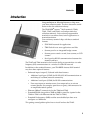
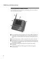
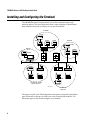
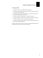
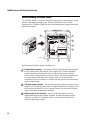
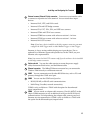
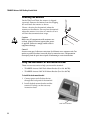
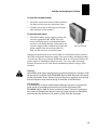
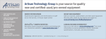
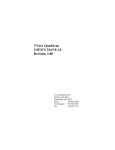
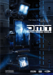
Getting Started Guide P/N 066961-002 ® TRAKKER Antares 248X Stationary Terminal ™ Intermec Technologies Corporation 6001 36th Avenue West P.O. Box 4280 Everett, WA 98203-9280 U.S. service and technical support: 1-800-755-5505 U.S. media supplies ordering information: 1-800-227-9947 Canadian service and technical support: 1-800-688-7043 Canadian media supplies ordering information: 1-800-268-6936 Outside U.S. and Canada: Contact your local Intermec service supplier. The information contained herein is proprietary and is provided solely for the purpose of allowing customers to operate and/or service Intermec manufactured equipment and is not to be released, reproduced, or used for any other purpose without written permission of Intermec. Information and specifications in this manual are subject to change without notice. 1998 by Intermec Technologies Corporation All Rights Reserved The word Intermec, the Intermec logo, JANUS, IRL, TRAKKER, Antares, Adara, Duratherm, EZBuilder, Precision Print, PrintSet, Virtual Wedge, and CrossBar are either trademarks or registered trademarks of Intermec Technologies Corporation. Throughout this manual, trademarked names may be used. Rather than put a trademark ( or ) symbol in every occurrence of a trademarked name, we state that we are using the names only in an editorial fashion, and to the benefit of the trademark owner, with no intention of infringement. Contents Contents Introduction 5 T248X Stationary Terminal Features 6 Unpacking the Terminal 7 Installing and Configuring the Terminal 8 Understanding the Back Panel 10 Attaching the Antenna 12 Using the Desk-Mount or Wall-Mount Bracket 12 Connecting Power and Input Devices 14 Charging the Backup Battery 15 Connecting to Serial Devices and Networks 16 Connecting Directly to an Ethernet Network 18 Connecting to an RF Network 19 Using the Menu System to Configure the Terminal 21 Using the Keypad 22 Using the Status Lights 23 Developing Applications for the Terminal 23 Specifications 24 Where to Find More Information 24 iii nugget c o d e Introduction 39 Introduction Congratulations on Selecting Intermec to help meet your data collection needs. You have chosen the world leader in the data collection industry. The TRAKKER® Antares™ 248X terminals (T2480, T2481, T2485, and T2486) are fixed-position data collection terminals. You use these programmable terminals to run either client/server applications or terminal emulation. Your stationary terminal ships with these standard features: 248XG.006 • 512K RAM reserved for applications • 750K flash drive to store applications and files • Scanner port for an integrated badge scanner • Scanner port to attach a wand, laser scanner, or CCD scanner • Serial port for RS-232 communications between the terminal and host The T2485 and T2486 terminals also have the ability to transmit data via radio frequency (RF) communications in a wireless 2.4 GHz RF network. In addition to the standard features, your TRAKKER Antares 248X terminal may have these optional features: • Enhanced input/output (I/O) board with these features: • Additional serial port (COM2) for RS-232/422/485 communications or multi-drop (CrossBar®) network connectivity • Additional serial port (COM4) for RS-232 communications • Four sense inputs to monitor events, four output relays to activate external devices (for example, open doors or gates), and connectors for an amplified external speaker • Ethernet (10BaseT) connectivity for the T2480 and T2481 • Extended SRAM storage drive (2MB or 4MB) to store files (option for the T2480 or T2481 with Ethernet and the T2485 or T2486) • Extended flash memory (2MB) to either store double-byte fonts or to configure as a 2MB drive This getting started guide explains how to install and use the T248X. 5 TRAKKER Antares 248X Getting Started Guide nugget c o d e 39 T248X Stationary Terminal Features The TRAKKER Antares 248X terminals are designed to make data collection easy and include these features: 5 1 4 2 3 248XG.022 6 1 CGA-compatible screen with graphics LCD. On the T2480 and T2485, the terminal has a 4 line by 40 character screen. On the T2481 and T2486, the terminal has a 12 line by 40 character screen that is configurable up to 25 lines. 2 Optional badge scanner (visible or infrared) for bar code data collection. 3 Alphanumeric (PC-style layout) or oversized function numeric keypad for data collection. The terminal ships with a keypad to match the application or language you ordered. 4 Status lights provide power, keypad, data, network, and scanning information. 5 Antenna on the T2485 and T2486 supports 2.4 GHz radio frequency communications. nugget c o d e Introduction 39 Unpacking the Terminal The TRAKKER Antares stationary terminal ships with: 4 1 3 5 2 Getting Started Guide P/N 066961-002 TRAKK 2486 ER Antares esc Q W ta I/O E A ? Cap s R S \ T D Z . U G C F7 F2 , Y F X F6 F1 / I H V F9 - ® ™ bks M p L : F4 F10 TRAKKER Antares 248X Stationary Terminal P K N F3 + O J B F8 Ctr & 7 l * 8 $ F5 Fn L Fn f 4 Ent er 9 % R 5 f 1 @ 6 2 < # Ins 3 0 Del > . 248XG.041 7 6 1 TRAKKER Antares 2480, 2481, 2485, or 2486 stationary terminal 2 Badge scanner, visible or infrared (optional) 3 Antenna for T2485 and T2486 4 Terminal blocks to connect sense inputs, output relays, and an amplified external speaker (ships only with the enhanced input/output board option) 5 Getting started guide and safety supplement 6 Labels for custom function key labels 7 Intermec power supply and North American power cord If you are using the terminal outside North America, you need to purchase a power cord for the power supply. When you remove the terminal from its box, save the box and shipping material in case you need to ship or store the terminal. Check the contents of the box against the invoice for completeness and contact your local Intermec service representative if there is a problem. 7 TRAKKER Antares 248X Getting Started Guide nugget c o d e 39 Installing and Configuring the Terminal The TRAKKER Antares 248X terminal has several communications and network options. The next illustration shows some examples of the different data collection networks in which you can use the terminal. CrossBar Printer T248X T248X T248X Ethernet Printer RS-232 9154/9161 T248X Host T2480/1 T2480/1 Host PC Ethernet Printer Access point T2485/6 DCS 300 T2485/6 T2485/6 2.4 GHz RF TCP/IP Direct Connect Access point T2485/6 Printer 248XG.030 2.4 GHz RF UDP Plus The steps to install your T248X depend on the options you purchased and the type of network or devices to which you want to connect the terminal. Use these next steps to install and configure your terminal. 8 nugget c o d e Installing 39 and Configuring the Terminal To install your T248X 1. Attach the antenna on a T2485 or T2486. See page 12. 2. If you have a wall-mount bracket, install it and install the terminal in the wall-mount bracket. See page 12. 3. Connect the power supply and input devices to the T248X. See page 14. 4. Charge the backup battery. See page 15. 5. Connect the T248X to serial devices or networks. See page 16. 6. Connect the T2480 or T2481 directly to an Ethernet network. See page 18. 7. Connect the T2485 or T2486 to an RF network. See page 19. 8. If you have a desk-mount bracket, install it and install the terminal in the desk-mount bracket. See page 12. Before you get started, use the next section to learn about the connectors and components inside the rear enclosure of the terminal. 9 TRAKKER Antares 248X Getting Started Guide nugget c o d e 39 Understanding the Back Panel To install the T248X, you must remove the back panel to connect power, input devices, and communications ports. The next illustration shows all the connectors on a T2480 or T2481 that has an enhanced input/output board and the Ethernet option. 9 1 2 3 4 8 248XG.025 7 6 5 Each feature on the back panel is defined next. 10 1 Terminal block connectors The terminal blocks (shipped with the terminal) let you connect four sense inputs, four output relays, and an amplified external speaker to the terminal. You use the sense inputs to monitor events, such as the opening or closing of a door. You use the output relays to actuate external devices, such as a door lock. The terminal block connectors are only available on a T248X with the option for the enhanced input/output board. 2 12V power supply connector The terminal operates using an external power supply. It has a backup battery that is designed to back up all memory and the real-time clock only in case of a power failure. You must have a power supply connected to operate the terminal. 3 Badge scanner (6-pin) connector You can order the terminal with an integrated badge scanner already installed, or order the badge scanner accessory to install at a later date. You can also attach an input device instead of the badge scanner. nugget 4 c o d e Installing 39 and Configuring the Terminal External scanner (Stewart 10-pin) connector You must use an interface cable to connect an input device to the terminal. You can attach these input devices: • Intermec 126X, 127X, and 128X wands • Intermec 1354 and 1355 badge scanners • Intermec 1516, 1517, 1518, 1519, and 1545 laser scanners • Intermec 1550A and 1551A laser scanners • Intermec 1550B laser scanner with software revision 1.9 or later • Intermec 1551B laser scanner with software revision 1.1 or later • Intermec 1463 CCD scanner Note: If you have a device installed on the badge scanner connector, you must configure the 1463 Trigger mode to either Manual Trigger or Auto-Trigger. Intermec is always testing and developing new input devices. For an updated list of Intermec-approved input devices for the T248X, see your Intermec sales representative. Note: You can use the 1464 CCD scanner only if you do not have a device installed on the badge scanner connector. 5 Cable restraint You use the cable restraint to secure the power supply cable, the terminal block wires, and the Ethernet cable. 6 Ethernet connector The 10BaseT Ethernet connector lets you connect the T2480 or T2481 directly to an Ethernet network. 7 COM1 You can communicate with other RS-232 devices, such as PCs and printers, through the COM1 serial port. 8 COM2 You can use the COM2 serial port for: • RS-232, RS-422, or RS-485 serial communications • Multi-Drop (CrossBar) network connectivity COM2 is only available on a T248X with the option for the enhanced input/output board. 9 COM4 You can attach an adapter cable accessory (Part No. 067185) to the 10-pin COM4 connector to use an additional serial port for RS-232 serial communications. For help ordering the adapter cable, contact your local Intermec service representative. COM4 is only available on a T248X with the option for the enhanced input/output board. 11 TRAKKER Antares 248X Getting Started Guide nugget c o d e 39 Attaching the Antenna On the T2485 and T2486, the antenna is shipped separately. Remove the antenna from the shipping box and attach the antenna as shown. Choose a location for the terminal where the antenna can be effective. Do not place the terminal where the antenna is too close to a metal wall or it will limit the communications range. Caution Make sure all components with antennas are at least 1 foot (0.3 meters) apart when power is applied. Failure to comply could result in equipment damage. 248XG.011 Conseil Assurez-vous que la distance entre tous les éléments avec antennes soit d’au moins un pied (0.3 mètres) avant de faire la connexion avec l’alimentation électrique, faute de quoi vous risquez d’endommager votre installation. Using the Desk-Mount or Wall-Mount Bracket There are two accessories to help you mount the terminal: • TRAKKER Antares 248X Desk-Mount Bracket (Part No. 066709) • TRAKKER Antares 248X Wall-Mount Bracket (Part No. 066708) To install the desk-mount bracket 1. Connect power and all other devices through the back panel of the terminal. 2. Install the desk-mount bracket and the terminal. For help, see the accessory instruction sheet. Desk-mount bracket 12 nugget c o d e Installing 39 and Configuring the Terminal To install the wall-mount bracket 1. Install the wall-mount bracket and the terminal. For help, see the accessory instruction sheet. 2. Connect power and all other devices through the back panel of the terminal. To mount the power supply • The T248X and the power supply are dust and moisture protected to IEC 60529/IP53 only when installed properly in the Intermec deskmount or wall-mount bracket. The brackets use a power supply holder to effectively protect the power supply from dust and moisture. For help, see the accessory instruction sheets. 248XG.021 Wall-mount bracket Intermec recommends that you use the desk or wall-mount bracket to mount the T248X and protect the power supply. You can use other mounting brackets or enclosures. However, without the Intermec desk or wall-mount bracket, the power supply is intended for indoor use only. Use of any other mounting brackets or enclosures will void the environmental protection ratings of the terminal. Warning Installation of the power supply must be performed strictly in accordance with the procedures contained in the TRAKKER Antares 248X desk and wall-mount bracket instruction sheets. Failure to protect the power supply in areas of high dust and moisture may result in injury or death due to electric shock. Avertissement L’installation de la source d’alimentation doit être exécutée en respectant de façon stricte les procédures décrites dans les feuilles d’instruction du TRAKKER Antares 248X de bureau et monté au mur. L’échec de la protection de la source d’alimentation dans des zones de grande poussière et d’humidité peut entraîner des blessures ou la mort en raison d’un choc électrique. 13 TRAKKER Antares 248X Getting Started Guide nugget c o d e 39 Connecting Power and Input Devices You connect power and input devices through the rear enclosure of the TRAKKER Antares 248X terminal. To connect the power supply and input devices 1. Use a Phillips screwdriver to remove the six screws on the back panel. Screw (6 places) 248XG.005 Back panel 2. Remove the back panel and place it on a clean surface. 3. Connect the power supply and input devices to the back of the terminal. 14 • Connect the power supply plug to the 12V power supply connector. Next, connect the power cord from the power supply to a powered electrical outlet. • Connect the badge scanner 6-pin connector to the badge scanner connector. • Connect the Stewart 10-pin connector from the input device to the external scanner connector. nugget c o d e Installing 39 and Configuring the Terminal Connecting the Power Supply and Input Devices External scanner connector Badge scanner connector 12V power supply connector 12V power supply plug Cable restraint 248XG.035 Cable restraint bar To power Scissors supply seal 4. Use a Phillips screwdriver to loosen one of the screws on the cable restraint. Route the power supply cable under the cable restraint. Tighten the screw to secure the cable. 5. Route all the cables under the cable restraint bar and through the scissors seal. 6. Leave the back panel off and continue with the instructions to connect other network devices. Charging the Backup Battery The backup battery backs up all memory and the real-time clock in case of a power failure. The backup battery is shipped inside the terminal, but may not be fully charged. You need to fully charge the backup battery after you install the terminal. To charge the backup battery 1. Make sure the power supply is connected to the terminal and a powered electrical outlet. 2. Let the power supply charge the backup battery for 24 hours to fully charge the backup battery. 15 TRAKKER Antares 248X Getting Started Guide nugget c o d e 39 Connecting to Serial Devices and Networks You use the terminal’s serial ports to transfer data between the terminal and a serial device. Every T248X has one serial port (COM1) that supports RS-232 communications. You can use COM1 to connect to a serial device, such as a printer, scale, or PC. The terminal has an option for an enhanced input/output board that provides two additional serial ports. COM2 supports RS-232/422/485 communications. You can use COM2 to connect to a serial device, a wired network, or an Intermec CrossBar network. COM4 supports RS-232 communications. You need the adapter cable accessory (Part No. 067185) to use COM4. To connect the COM ports 1. Connect the 9-pin RS-232 connector from a serial device to the COM1 connector on the back of the terminal. COM4 COM1 248XG.036 COM2 To device 2. Connect the 25-pin serial or multi-drop connector from a serial device or network to the COM2 connector on the back of the terminal. 3. Connect the 9-pin RS-232 connector from a serial device to the COM4 adapter cable on the back of the terminal. 4. Route the cables under the cable restraint bar and through the scissors seal. 5. With the seal facing toward the terminal, place the back panel on the back of the terminal. 6. Use a Phillips screwdriver to tighten the six screws to 19 in-lb torque. 16 nugget 7. Press the c o d e Installing 39 and Configuring the Terminal f key on the keypad. The Boot Menu appears. Note: If the backup battery charge is low, you may need to press information screen. ] to exit a battery to boot the terminal and initialize the firmware. The TRAKKER 8. Press Antares screen appears. Next, either a sample application screen or a terminal emulation (TE) application welcome screen appears. Note: On a T248X loaded with terminal emulation, you may need to press create the TE configuration file. to 9. Configure COM1, COM2, or COM4 using the next instructions. To configure COM1, COM2, or COM4 to communicate with serial devices 1. Use the TRAKKER Antares 2400 Menu System to set these COM1, COM2, or COM4 serial port parameters: • Time and date • Protocol (default is Configurable) • Baud rate • Optional parameters (depending on the protocol): Parity, Data bits, Stop bits, Flow control, EOM, SOM, LRC, Handshake, and Commands Via Serial Port For help, see “Using the Menu System to Configure the Terminal” later in this guide. Note: For COM4, the Scanner Port field is only used on the TRAKKER Antares 242X hand-held terminals. For the T248X, the Scanner Port field (if shown) is ignored. 2. Configure the serial port parameters for the serial device (for example, a PC) to which you are connecting the terminal. The values you set for the terminal’s serial port must match the values set for the device’s serial port. To configure COM2 to communicate in an Intermec CrossBar network 1. Use the TRAKKER Antares 2400 Menu System to set these COM2 serial port parameters: • Time and date • Protocol = Multi-Drop • Baud rate • Multi-Drop address 17 TRAKKER Antares 248X Getting Started Guide nugget c o d e 39 For help, see “Using the Menu System to Configure the Terminal” later in this guide. 2. Configure your 9154 or 9161 controller to add the new multi-drop T248X device. For help, see your controller user’s manual. Connecting Directly to an Ethernet Network The TRAKKER Antares 2480 and 2481 terminals have an option for an Ethernet (10BaseT) card. With this option, your terminal can communicate to a host or any device on an Ethernet network. To connect to an Ethernet network 1. Configure your host computer and network. Assign an IP address for the T2480 or T2481. 2. Connect the Ethernet jack to the Ethernet connector on the back of the terminal. Ethernet connector 248XG.038 To Ethernet network 3. Use a Phillips screwdriver to loosen one of the screws on the cable restraint. Route the Ethernet cable under the cable restraint. Tighten the screw to secure the cable. 4. Route the cable under the cable restraint bar and through the scissors seal. 5. With the seal facing toward the terminal, place the back panel on the back of the terminal. 6. Use a Phillips screwdriver to tighten the six screws to 19 in-lb torque. 18 nugget c o d e Installing 39 and Configuring the Terminal 7. Plug the other end of the Ethernet cable into an Ethernet jack on your network. 8. Press the f key on the keypad. The Boot Menu appears. Note: If the backup battery charge is low, you may need to press information screen. ] to exit a battery to boot the terminal and initialize the firmware. The TRAKKER 9. Press Antares screen appears. Next, either a sample application screen or a terminal emulation (TE) application welcome screen appears. Note: On a T248X loaded with terminal emulation, you may need to press create the TE configuration file. to 10. Use the TRAKKER Antares 2400 Menu System to set these network parameters: • Time and date • Network activate (Ethernet) • Controller IP address (UDP Plus) or Host IP address (TCP/IP) • Terminal IP address • Network port For help, see “Using the Menu System to Configure the Terminal” later in this guide. Connecting to an RF Network The TRAKKER Antares 2485 or 2486 terminal can communicate with a host computer in Intermec’s 2.4 GHz RF network either through the DCS 300 or directly through the access points. The terminal uses one of these RF network protocol options to communicate with other devices: • UDP Plus • TCP/IP Each T2485 or T2486 ships with only one of these RF network protocols. To configure the T2485 or T2486 to use RF communications 1. Configure the DCS 300 (UDP Plus) or host (TCP/IP). For help with the DCS 300, see the DCS 300 System Manual (Part No. 067296). Note: You can use the DCS 300 or Model 200 Controller. For help with the controller, see the Model 200 Controller System Manual (Part No. 063439). 2. Configure the access point. For help, see your access point user’s manual. 19 TRAKKER Antares 248X Getting Started Guide nugget c o d e 39 Connecting to an RF Network Host TCP/IP Direct Connect UDP Plus Ethernet Access point T2485/6 DCS 300 T2485/6 T2485/6 Access point T2485/6 248XG.032 3. Press the f key on the keypad. The Boot Menu appears. Note: If the backup battery charge is low, you may need to press information screen. ] to exit a battery to boot the terminal and initialize the firmware. The TRAKKER 4. Press Antares screen appears. Next, either a sample application screen or a terminal emulation (TE) application welcome screen appears. Note: On a T2485 or T2486 loaded with terminal emulation, you may need to to create the TE configuration file. press 5. Use the TRAKKER Antares 2400 Menu System to set these network parameters: • Time and date • Network activate (2.4 GHz) • Controller IP address (UDP Plus) or Host IP address (TCP/IP) • Terminal IP address • RF domain • RF security identification (ID) • Network port (TCP/IP) Note: If the T2485 or T2486 is on a different IP subnetwork from the DCS 300 or host, you must also configure the default router and subnet mask. 20 nugget c o d e Installing 39 and Configuring the Terminal For help, see the next section, “Using the Menu System to Configure the Terminal.” Using the Menu System to Configure the Terminal You use the TRAKKER Antares 2400 Menu System to set serial port or network parameters on the T2480, T2481, T2485, or T2486. To configure the terminal 1. Press or scan this bar code to access the TRAKKER Antares 2400 Menu System: Enter Test and Service Mode *..-.* *..-.* The Main Menu appears. 2. Choose the System Menu and then press . Use the Set Time and Date option to set the current time and date. For help in the menu system, press . 248XG.014 b ] to exit the System Menu. The Main Menu appears. Choose the Configuration Menu and then press . The Configuration 3. Press 4. Menu appears. Use the Communications Menu to configure the network parameters and the serial port parameters. CONFIGURATION MENU Symbologies Menu Communications Menu Terminal Menu ⁄ _` Select item [Enter] Next screen [F1] Help [Esc] Exit 248XG.015 ] 5. Press to exit the Configuration Menu. When prompted, save your changes to RAM. Press to exit the Main Menu and save your changes in flash memory. ] 21 TRAKKER Antares 248X Getting Started Guide nugget c o d e 39 Using the Keypad The terminals come with a color-coded keypad to make it easier to remember key combinations. Position on the Keypad Color To Type the Character Middle of the key or centered above the key Grey Press the key. Left side above the key Orange Centered above a numeric key Green Right side above the key Blue key, then the key. Press the green key, then the key. Press the blue key, then the key. Press the orange Your terminal ships with function key labels. You can use the labels to identify custom function keys. Write the name for each function key on a strip of five labels. Insert the strip into the slot above the function keys. Note: There are two sizes of function key labels. Use the labels that are slightly larger if you have a T248X with an oversized function numeric keypad. Use the smaller labels for an alphanumeric keypad. \ ? esc Q tab E W S A R F D . , / T U Y G H J F6 P L bksp : Ctrl Z " F7 F1 O K Caps I/O - + I X F8 F2 C V F4 N M Fn L Fn R _f _ _f Enter F10 F9 F3 B F5 & * 7 8 $ % 4 5 6 ! @ # 1 2 3 < Ins 9 Del 0 > . 248XG.040 22 nugget c o d e Using 39the Status Lights Using the Status Lights You can use the terminal’s status lights to monitor the status of backup battery power, RF and network communications, special keys, and bar code scanning. The status lights only flash or turn on to indicate the current status. Power Network Connect Network Transmit Modifier Key Caps Lock Good Read User Defined 248XG.016 Developing Applications for the Terminal The TRAKKER Antares terminals ship loaded with a terminal emulation application, a screen mapping application, or a sample application. You can develop your own client/server application for the T248X and then download the application to the terminal. Intermec has two development tools that you can use to create applications: • TRAKKER Antares Programmer’s Software Kit (Part No. 065332) has a full set of programming tools to help you create applications for the terminal. • EZBuilder™ (Part No. 066381) is a rapid application development tool that provides programmers and technically-oriented non-programmers with a quick and easy way to create applications for the terminal. 23 TRAKKER Antares 248X Getting Started Guide nugget c o d e 39 Specifications Terminal Dimensions Length: 10.7 in (27.2 cm) 11.3 in (28.7 cm) with a badge scanner installed Height: 9.6 in (24.4 cm) Depth: 3.9 in (9.9 cm) Weight: 9.5 lbs (4.3 kg) Power Specifications Operating (with power supply): 95 to 250 VAC, 50 to 60 Hz, 125 mA Memory Backup: Rechargeable NiCad 700 mA battery pack Electrical Specifications Models: Electrical rating: T2480, T2481, T2485, and T2486 S 12V, 750 mA Temperature and Environmental Specifications Operating the terminal: -4°F to +122°F -20°C to +50°C Storing the terminal: -4°F to +140°F -20°C to +60°C Charging the backup battery: +32°F to +104°F 0°C to +40°C Relative humidity: 0 to 95% non-condensing Memory • 2MB programmable flash memory, 750K available for use • 1MB battery-backed RAM, 512K available for use • Extended memory option for an additional 2MB flash • Extended memory option for an additional 2MB or 4MB SRAM storage drive (option for the T2480 or T2481 with Ethernet and the T2485 or T2486) Where to Find More Information The TRAKKER Antares 248X Stationary Terminal User’s Manual (Part No. 066960) contains all the information necessary to install, configure, operate, and troubleshoot the T248X. For information on ordering a manual, contact your local Intermec sales representative. 24